Article

A Consideration on Maximum Efficiency of Resonant Circuit of Inductive Power Transfer System with Soft-Switching Operation

by
Ryosuke Ota
1,2,*,
Dannisworo Sudarmo Nugroho
1 and
Nobukazu Hoshi
1
1
Department of Electrical Engineering, Faculty of Science and Technology, Tokyo University of Science, 2641 Yamazaki, Noda-city, Chiba 278-8510, Japan
2
JSPS Research Fellow (PD), Japan Society for the Promotion of Science, Sumitomo-Ichibancho Bldg., 6 Ichibancho, Chiyoda-ku, Tokyo 102-8471, Japan
*
Author to whom correspondence should be addressed.
World Electr. Veh. J. 2019, 10(3), 54; https://doi.org/10.3390/wevj10030054
Submission received: 24 July 2019 / Revised: 6 September 2019 / Accepted: 9 September 2019 / Published: 11 September 2019
(This article belongs to the Special Issue Power Electronics Subsystems)

Abstract

:
By using bi-directional inductive power transfer (IPT) systems as battery chargers for electric vehicles (EVs), battery charging operations become convenient and safe. However, IPT systems have problems such as occurrences of much electromagnetic noise and power loss because the converters of IPT systems are driven in high frequency by tens of kHz. To solve these problems, there is a case where the soft-switching technique needs to be applied to the converters of IPT systems. However, in soft-switching operation, the power factor of the resonant circuit becomes lower, resulting in a lower resonant circuit efficiency. In previous works, when the soft-switching technique was applied to the converters, the resonant circuit had not always been able to be operated with high efficiency because the influence caused by soft-switching operation had not been considered. For this reason, there was a case where the efficiency of the overall system with soft-switching operation became lower than the efficiency in hard-switching operation. Therefore, in this paper, the influence on the efficiency of the resonant circuit caused by the soft-switching operation is clarified by the theoretical analysis and experiments; then, the guideline for improving the efficiency of IPT systems is shown. As a result, in the experiments, it could be understood that the efficiency of the overall system with soft-switching operation becomes higher than the efficiency in hard-switching operation when the operating point of the resonant circuit was close to the requirement guideline, which is shown by using the primary-side voltage and the secondary-side voltage of the resonant circuit. Therefore, it is suggested that the efficiency of IPT systems could be improved by properly regulating the primary-side direct current (DC) voltage.

Graphical Abstract

1. Introduction

There is an adjustment method for supply and demand balance in a power system by utilizing the batteries on electric vehicles (EVs) as a part of energy storage systems [1,2,3,4,5]. In that case, these systems can be safe and maintainable by using bi-directional inductive power transfer (IPT) systems as battery chargers for EVs [1,2,6,7,8,9,10,11]. However, IPT systems have a problem in that the power loss is larger than that of wired plug-in charging systems. The large power loss causes the increase of wasteful energy consumption and the size and weight of a system. Thus, to familiarize IPT battery charging systems, it is very important to reduce the power loss. For these reasons, research related to improving the efficiency has been conducted actively.
Previously, the maximum-efficiency-tracking method for the resonant circuit [2,7,8,9,12,13,14,15], the design method for the resonant circuit [2,11,16], the switching frequency control method for the secondary-side converter [14,17], and the soft-switching technique [9,15,18,19,20] were proposed as the efficiency improvement method for IPT systems. In general IPT systems, much electromagnetic noise and power loss occur because the converters of IPT systems are driven in high switching frequency by tens of kHz. For these problems, there is a case where the soft-switching technique needs to be applied to the converters of IPT systems [9,15,19,20,21].
However, in soft-switching operation, the power factor of the resonant circuit becomes lower, which causes the efficiency of the resonant circuit to be lower. This is because it is necessary to have the phase difference between the output voltage and the output current of the converters when the soft-switching technique is applied to the converters. Thus, there is a case where the efficiency of the overall system with soft-switching operation becomes lower than the efficiency without soft-switching operation if soft-switching operation is not applied to the converters appropriately. From the above, when the soft-switching technique is applied to the converters in IPT systems, it is necessary to consider the influences caused by soft-switching operation. However, in previous works, these influences have not been clarified, and the resonant circuit and the system have not been able to be operated in high efficiency [9,15,19,20]. Therefore, in this paper, the influences on the efficiency of the resonant circuit caused by soft-switching operation are clarified by the theoretical analysis and experiments. Moreover, the guideline for improving the power transfer efficiency of IPT systems is shown.

2. System Overview

2.1. Derivation of Voltage and Current in a Bi-Directional inductive power transfer (IPT) System

Figure 1 shows the inductive power transfer system used in this study.
This IPT system is constructed from two active bridges and an SS-type resonant circuit. The SS-type resonant circuit is a circuit where compensation capacitors are connected to the transmission coils in series. In this system, as the control inputs, there is a phase shift amount between the legs of the gating signals in the primary-side active bridge α 1 [rad] ( 0 α 1 π θ d ), the phase shift amount between the legs of the gating signals in the secondary-side active bridge α 2 [rad] ( 0 α 2 π θ d ), and the phase shift amount between the gating signals for S 11 and S 21 δ [rad]. The relationships between these gating signals and the output voltage waveforms of the active bridges with soft-switching operation are shown in Figure 2.
In addition, θ d [rad] is the angular quantity derived from the ratio of the dead-time length accounting in the switching period; this angle is named “angle equivalent to dead-time length" in this paper. The output voltages V ˙ 1 , V ˙ 2 [V] and currents I ˙ 1 , I ˙ 2 [A] of the active bridges can be regulated by controlling these inputs. In addition, the active bridges can achieve soft-switching operation by controlling these inputs appropriately. In the soft-switching operation, the output voltage waveforms of the active bridges are shown in Figure 2. However, in this system, the angular frequency of the output of active bridges ω act [rad/s] is set at constant to resonant frequency from the viewpoint of the leakage magnetic field.
In the SS-type resonant circuit, the capacitances of compensation capacitors C 1 , C 2 [F] are designed to resonate with the self-inductances of transmission coils L 1 , L 2 [H], respectively, at 85 kHz. In this case, each characteristic of the resonant circuit can be considered with only V ˙ 1 _ 1 , V ˙ 2 _ 1 [V], which is the fundamental component of V ˙ 1 , V ˙ 2 , respectively, because the resonant circuit works as a band-pass filter at the resonant frequency of 85 kHz. Therefore, based on Figure 2, when soft-switching operation is applied to the active bridges, V ˙ 1 _ 1 and V ˙ 2 _ 1 are expressed as
V ˙ 1 _ 1 = 2 2 E 1 π cos α 1 2 ε j α 1 2 + θ d 2 and
V ˙ 2 _ 1 = 2 2 E 2 π cos α 2 2 ε j δ α 2 2 + θ d 2 ,
where the positive directions of the voltages are shown with the arrows in Figure 1, and the phases of voltages are based on the phase of the gating signal for S 11 . In this case, the output currents of the active bridges I ˙ 1 _ 1 and I ˙ 2 _ 1 [A] are expressed as
I ˙ 1 _ 1 = j V ˙ 2 _ 1 ω act M
= 2 2 E 2 π ω act M cos α 2 2 ε j π 2 + δ α 2 2 + θ d 2 and
I ˙ 2 _ 1 = j V ˙ 1 _ 1 ω act M
= 2 2 E 1 π ω act M cos α 1 2 ε j π 2 α 1 2 + θ d 2 ,
where the positive directions of the currents are shown with the arrows in Figure 1, and M [H] is the mutual inductance between the primary-side coil and the secondary-side coil. From (1)–(6), it is confirmed that the phase of I ˙ 1 _ 1 delays by π / 2 from the phase of V ˙ 2 _ 1 , and the phase of I ˙ 2 _ 1 leads by π / 2 from the phase of V ˙ 1 _ 1 . Thus, each I ˙ 1 _ 1 and I ˙ 2 _ 1 can be controlled without interference from the phases of I ˙ 2 _ 1 and I ˙ 1 _ 1 respectively in soft-switching operation. Regarding the requirements for soft-switching operation, the detail of Figure 2 will be explained in the following section.

2.2. Transmission Power and Efficiency

Figure 3 shows the equivalent circuit of an SS-type resonant circuit.
When the power loss in the system is ignored, the transmission power P tr [W] can be expressed as the following equation [2]:
P tr = V ˙ 1 _ 1 V ˙ 2 _ 1 ω M sin δ ,
where δ [rad] is the phase shift amount between V ˙ 1 _ 1 and V ˙ 2 _ 1 . δ is expressed as
δ = α 1 2 α 2 2 + δ .
The efficiency of the resonant circuit η rc [%] is expressed as
η rc = 100 P tr P tr + r 1 I ˙ 1 2 + r 2 I ˙ 2 2 ,
where r 1 and r 2 [ Ω ] are the ESR of primary-side coil L 1 and secondary-side coil L 2 , respectively. When it is assumed that the quality factors of coils Q are equal to each other, η rc can be expressed as the following equation [2]:
η rc = 100 1 + V ˙ 2 _ 1 V ˙ 1 _ 1 L 1 L 2 + V ˙ 1 _ 1 V ˙ 2 _ 1 L 2 L 1 k Q sin δ ,
where k is the coupling coefficient between the transmission coils. From the denominator of (10), the conditions for the maximum efficiency of the resonant circuit can be derived by using the relationship of arithmetic-geometric mean. These conditions are expressed as the following equation [2].
δ = π 2 and
L 2 L 1 = V ˙ 2 _ 1 V ˙ 1 _ 1 2 = I ˙ 1 _ 1 I ˙ 2 _ 1 2 .
Equation (11) shows the requirement for maintaining the highest power factor of the resonant circuit. Equation (12) shows the requirement for balancing between the primary-side current and the secondary-side current. The reason why the balancing requirement is important is that the deviation between both sides of the currents induces the undesirable copper loss. Thus, in the condition where δ is fixed to a value, the sum of the losses in the resonant circuit becomes the smallest when (12) is satisfied.
However, when soft-switching operation is applied to the active bridges, it is difficult to satisfy these requirements simultaneously because it is necessary to set the phase difference between the output voltage and the output current of the active bridges. Thus, there is a case where the efficiency of overall system with soft-switching operation becomes lower than the efficiency without soft-switching operation if soft-switching operation is not applied to the converters appropriately. From the above, when soft-switching technique is applied to the converters in IPT systems, it is necessary to consider the influences of the soft-switching operation. However, in previous works, these influences had not been clarified, and the resonant circuit and the system had not been operated under high efficiency requirements. Therefore, in the following sections, the influences on the efficiency of the resonant circuit caused by soft-switching operation are clarified by the theoretical analysis.

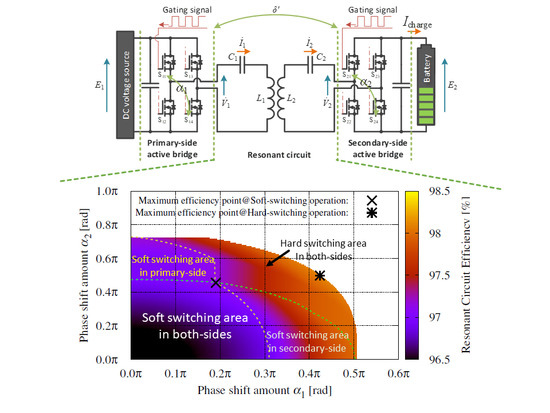
3. Influences of Soft-Switching Operation

3.1. Requirement for Soft-Switching Operation

Figure 4 shows the transition diagram of the operation mode focusing on turning S 11 on with soft switching.
The soft-switching operation upon turning on can be achieved by turning the switch on while the drain-source (D–S) voltage across the switch is zero. In other words, in order to achieve the soft-switching operation, it is necessary that the electric charge stored in the snubber capacitor, which is connected to the switch in parallel for protecting the steep change of the D–S voltage, is discharged completely before turning the switch on. To discharge the electric charge, it is necessary to make the reverse current flows through the switch during the dead time as shown in Figure 4.
In Figure 2, the conditions for achieving soft switching in the primary-side and secondary-side active bridges can be confirmed. In addition, the period indicated by hatching shows the dead time in each leg. According to Figure 2, the reverse current flows through the switch during the dead time by setting a zero-crossing point of the currents within the period indicated by hatching. In this time, if the reverse current is sufficiently large, the electric charge is discharged completely, and D–S voltage becomes zero. Consequently, the soft switching can be achieved in all switches in the active bridge. From the above, the requirement where soft-switching can be achieved at all switches in both active bridges can be expressed as
π + θ d 2 θ i 1 θ d 2 α 1 , δ + θ d 2 θ i 2 π θ d 2 α 2 + δ ,
where θ i 1 and θ i 2 [rad] are the phases of the primary-side current and the secondary-side current based on the phase of gating signal for S 11 . In (13), the inequality regarding θ i 1 shows the soft-switching requirement for the primary-side active bridge, and the inequality regarding θ i 2 shows the soft-switching requirement for the secondary-side active bridge. However, in this paper, the dead time length is assumed to be sufficiently long for the discharging time of the electric charge, and the influence on the requirements for soft-switching operation caused by the discharging is not considered.
In addition, in this paper, only the battery charging mode is assumed. When the transmission power P tr becomes positive and (13) is also considered, the requirement of the control input δ for achieving soft-switching operation can be expressed as
α 2 2 α 1 2 < δ π 2 α 1 + α 2 2 θ d α 1 + 2 θ d α 2 , α 2 2 α 1 2 < δ π 2 α 1 2 α 1 + 2 θ d < α 2 .

3.2. Analysis for Efficiency of the Resonant Circuit
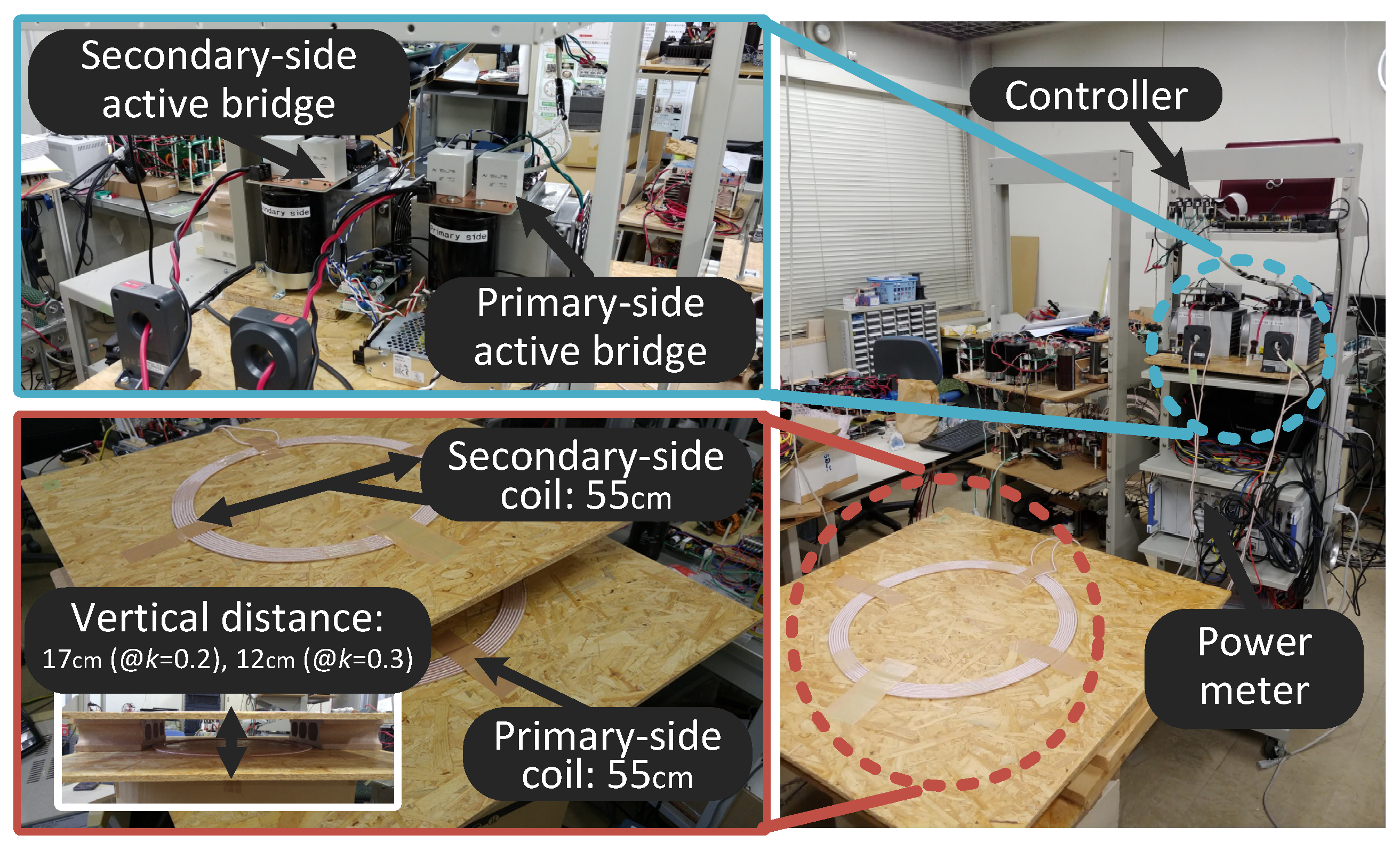
In this section, the influences on the efficiency of the resonant circuit caused by soft-switching operation are clarified. Table 1 shows the circuit parameters for the analysis. Figure 5 shows the efficiency map of the resonant circuit when the battery charging current I charge [A] is 8 A.
In Figure 5, the x-axis shows the phase shift amount between the legs of the primary-side active bridge α 1 [rad] and the y-axis shows the phase shift amount between the legs of the secondary-side active bridge α 2 [rad]. In each point, the phase shift amount δ [rad], which is between the gating signals for S 11 and S 21 , is regulated so as I charge = 8 A. In addition, the dotted lines show the boundary lines for the operation modes of the active bridges. Inside of the boundary lines, which mean in the lower left of the map, all switches of the active bridges can achieve soft-switching (SSW) operation. However, in this paper, the operation mode where at least one of the legs in the active bridge is operated in hard switching is defined as a hard-switching (HSW) operation.
In addition, the boundary lines have been drawn based on the operation mode of the active bridges, respectively. In the soft-switching operation area, the boundary line I is drawn based on the condition expressed as
θ i 1 = θ d 2 α 1 .
In this condition, the zero-crossing point of I 1 exists on the left end of the range for achieving soft-switching operation in Figure 2a. On the other hand, in the soft-switching operation area, the boundary line II is drawn based on the condition expressed as
θ i 2 = δ + θ d 2 .
In this condition, the zero-crossing point of I 2 exists on the right end of the range for achieving soft-switching operation in Figure 2b. However, outside of the bounded area where all switches of both active bridges cannot achieve soft-switching operation, the boundary lines cannot be expressed by these equations because the current through anti-parallel diode commutes during the dead time. The detail of the considerations on these boundary lines will be reported in a future report.
From Figure 5, it is confirmed that the efficiency of the resonant circuit considering soft-switching operation becomes the highest at the point where the boundary lines I and II intersect. Thus, this crossing point satisfies the conditions (15) and (16), and the condition for the crossing point is expressed as
α 1 + 2 θ d = α 2 .
In condition (17), the power factor of the resonant circuit becomes the highest because the difference of the phases between the voltages and the currents becomes the smallest. Therefore, the efficiency of the resonant circuit becomes higher. In addition, (17) can be confirmed by Figure 6, which shows the loci of the maximum efficiency points of the resonant circuit when I charge is varied. In Figure 6, I charge becomes larger, i.e., the output power becomes larger, on the range where α 1 and α 2 are set to smaller values. As shown in Figure 6, the loci of the maximum efficiency points are in accordance with (17) when E 2 / E 1 does not deviate from one, which is the requirement for high efficiency based on (12). This is because the influence of (11) becomes more dominant than the influence of (12) on the efficiency. Thus, the influence of (12) can be ignored when E 2 / E 1 does not deviate far from (12). On the other hand, when E 2 / E 1 deviates further from (12), the locus of the maximum efficiency points deviate from the line expressed by (17). Therefore, a novel equation considering the influence of (12) is necessary when the influence of (12) can not be ignored. The details of this influence will be reported in a future report.
In addition, in the entire operating range, it can be confirmed from Figure 5 that the efficiency of the resonant circuit becomes the highest when conditions (11) and (12) are satisfied. However, the maximum efficiency point in the entire operating range does not match the maximum efficiency point in the soft-switching operating range. Thus, applying the soft-switching technique to IPT systems makes the efficiency of the resonant circuit lower; however, the efficiency of the active bridges can be improved. In other words, there is a possibility that the efficiency of overall systems can be improved when the decrease of the switching losses with soft-switching operation becomes larger than the increase of the conduction loss of the resonant circuit.
Incidentally, when comparing Figure 5a,b in regard to the maximum points of each operation mode, it is confirmed that the efficiency drop caused by soft-switching operation in Figure 5b is smaller than that in Figure 5a. The reason is that the efficiency drop by deviation from (12) is small in soft-switching operation when E 2 / E 1 equals one. Thus, there is a possibility that the efficiency of overall systems can be improved depending on the value of E 2 / E 1 .
In the experiments, the influence of the soft-switching operation is clarified.

4. Experiments

In the experiments, the influence on the overall system caused by the soft-switching operation is clarified by comparing the overall efficiencies in the soft-switching operation and the hard-switching operation. Table 2 shows the parameters used in the experiments and Figure 7 shows the appearance of the experimental setup of Figure 1. In addition, Figure 8 shows an overview of the experimental setup. In this experimental setup, the system is controlled in open-loop by just one controller for simplification in order to synchronize both-sides active bridges. In actual systems, as one of the methods for the synchronization of the active bridges, the method where the zero-cross points of the resonant circuit currents are detected by current sensors can be assumed; however, this subject will be discussed in a future report. Figure 9 shows the efficiency of the overall system. In the soft-switching operation, the resonant circuit is operated according to the maximum efficiency condition expressed in Figure 6. In the hard-switching operation, the resonant circuit is operated according to the maximum efficiency condition expressed as (11) and (12).
From Figure 9a, it can be confirmed that the efficiency in the hard-switching operation becomes higher than the efficiency in the soft-switching operation. The reason is that the efficiency drop is large due to the deviation of E 2 / E 1 from one in the soft-switching operation. On the other hand, from Figure 9b, it can be confirmed that the efficiency in the soft-switching operation becomes higher than the efficiency in the hard-switching operation. The maximum improvement value is 0.5% when the output power is 2.4 kW. The reason is that the efficiency drop by deviation from (12) is small in the soft-switching operation when E 2 / E 1 equals one. On the contrary, when the output power is low, the efficiency in the hard-switching operation becomes higher than the efficiency in the soft-switching operation. This is because V ˙ 2 _ 1 / V ˙ 1 _ 1 deviates further from one as the output power becomes lower.
This is confirmed from the equation expressed as
V ˙ 2 _ 1 V ˙ 1 _ 1 = E 2 E 1 cos α 1 + 2 θ d 2 cos α 1 2 ,
where α 2 = α 1 + 2 θ d . From the above, there is a possibility where the efficiency of IPT systems can be improved by controlling E 1 to the optimum value where V ˙ 2 _ 1 / V ˙ 1 _ 1 satisfies (12). At this time, E 1 can be controlled by using an active filter system connected to a grid.
In addition, Figure 10 shows the waveforms of voltages and currents in the resonant circuit at E 1 = 200 V, E 2 = 150 V, and I c h a r g i n g = 8 A. It can be confirmed that the soft-switching operation can be achieved.
From the above, the influences on the efficiency of the resonant circuit with the soft-switching operation were clarified by the theoretical analysis and the experiments, and the guideline for improving the IPT systems efficiency was shown.

5. Conclusions

The basic characteristics of bi-directional IPT systems were shown. In addition, the requirements for obtaining the maximum efficiency of the resonant circuit considering soft-switching operation were clarified by the theoretical analysis. Furthermore, the relationship between the soft-switching operation and the hard-switching operation regarding the efficiency was clarified. In the experiments, it could be understood that the efficiency in the soft-switching operation becomes higher than the efficiency in the hard-switching operation when the operating point of the resonant circuit was close to the high-efficiency condition (12). In addition, the maximum improvement value was 0.5% when the output power was 2.4 kW. The reason was that the efficiency drop due to the deviation from (12) was small in the condition. As a result, it was suggested that the efficiency of IPT systems could be improved by properly regulating the primary-side DC voltage E 1 , which can be controlled by using an active filter system connected to a grid. Moreover, it was shown that there was a possibility where the efficiency of IPT systems could be improved by controlling E 1 to the optimum value where V ˙ 2 _ 1 / V ˙ 1 _ 1 satisfied (12).
From the above, the influences on the efficiency of the resonant circuit with soft-switching operation were clarified by the theoretical analysis and experiments, and the guidelines for improving the efficiency of IPT systems were shown. In future work, the effectiveness of the proposed guideline will be clarified by using an active filter system connected to a grid for controlling the primary-side DC voltage of IPT systems.

Author Contributions

Conceptualization, R.O. and H.N.; software, R.O.; investigation, R.O.; resources, N.H and R.O.; data curation, N.H and R.O.; writing—original draft preparation, R.O.; writing—review and editing, R.O., N.H, and D.S.N; supervision, N.H; project administration, R.O. and N.H; funding acquisition, R.O.

Funding

This work was supported by JSPS KAKENHI Grant No. JP18J12166.

Conflicts of Interest

The authors declare no conflict of interest.

Abbreviations

The following abbreviations are used in this manuscript:
EVElectric vehicle
IPTInductive power transfer

References

  1. Cabrera, A.T.; Sanchez, J.A.A.; Longo, M.; Foiadelli, F. Sensitivity analysis of a bidirectional wireless charger for EV. In Proceedings of the 2016 IEEE International Conference on Renewable Energy Research and Applications (ICRERA), Birmingham, UK, 20–23 November 2016; pp. 1113–1116. [Google Scholar] [CrossRef]
  2. Ota, R.; Kakomura, K.; Hoshi, N.; Sato, D.; Transfer, C.E. Maximum Efficiency Control Scheme and Design Method for Resonant Circuit of Bi-directional Inductive Power Transfer System. In Proceedings of the 2017 European Power Electronics and Drives Association & the Institute of Electrical and Electronics Engineers, Warsaw, Poland, 11–14 September 2017; pp. 1–9. [Google Scholar]
  3. Khaki, B.; Sharaf, A. A hybrid multi-loop controlled facts-based smart v2g battery charger. Int. J. Renew. Energy Res. 2013, 3, 155–160. [Google Scholar]
  4. Kirmani, S.; Jamil, M.; Akhtar, I. Bi-directional power control mechanism for a microgrid hybrid energy system with power quality enhancement capabilities. Int. J. Renew. Energy Res. 2017, 7, 1962–1965. [Google Scholar]
  5. Gori, P.A.; Sadarnac, D.; Caillierez, A.; Loudot, S. Sensorless inductive power transfer system for electric vehicles: strategy and control for automatic dynamic operation. In Proceedings of the 19th European Conference on Power Electronics and Applications (EPE’17 ECCE Europe), Warsaw, Poland, 11–14 September 2017. [Google Scholar] [CrossRef]
  6. Madawala, U.K.; Neath, M.; Thrimawithana, D.J. A power-frequency controller for bidirectional inductive power transfer systems. IEEE Trans. Ind. Electron. 2013, 60, 310–317. [Google Scholar] [CrossRef]
  7. Pellitteri, F.; Boscaino, V.; Di Tommaso, A.O.; Miceli, R. Efficiency optimization in bi-directional inductive power transfer systems. In Proceedings of the 2015 International Conference on Electrical Systems for Aircraft, Railway, Ship Propulsion and Road Vehicles (ESARS), Aachen, Germany, 3–5 March 2015; pp. 1–6. [Google Scholar] [CrossRef]
  8. Diekhans, T.; De Doncker, R.W. A Dual-Side Controlled Inductive Power Transfer System Optimized for Large Coupling Factor Variations and Partial Load. IEEE Trans. Power Electron. 2015, 30, 6320–6328. [Google Scholar] [CrossRef]
  9. Samanta, S.; Rathore, A.K. A New Inductive Power Transfer Topology Using Direct AC-AC Converter with Active Source Current Waveshaping. IEEE Trans. Power Electron. 2017, 30, 5565–5577. [Google Scholar] [CrossRef]
  10. Swain, A.K.; Neath, M.J.; Madawala, U.K.; Thrimawithana, D.J. A dynamic multivariable state-space model for bidirectional inductive power transfer systems. IEEE Trans. Power Electron. 2012, 27, 4772–4780. [Google Scholar] [CrossRef]
  11. Huang, Z.; Wong, S.C.; Tse, C.K. Design of a Single-Stage Inductive-Power-Transfer Converter for Efficient EV Battery Charging. IEEE Trans. Veh. Technol. 2017, 66, 5808–5821. [Google Scholar] [CrossRef]
  12. Koyama, T.; Umetani, K.; Hiraki, E. Design Optimization Method for the Load Impedance to Maximize the Output Power in Dual Transmitting Resonator Wireless Power Transfer System. IEEJ J. Ind. Appl. 2018, 7, 49–55. [Google Scholar] [CrossRef] [Green Version]
  13. Lovison, G.; Kobayashi, D.; Sato, M.; Imura, T.; Hori, Y. Secondary-side-only Control for High Efficiency and Desired Power with Two Converters in Wireless Power Transfer Systems. IEEJ J. Ind. Appl. 2017, 6, 473–481. [Google Scholar] [CrossRef] [Green Version]
  14. Ota, R.; Nugroho, D.S.; Hoshi, N. Efficiency Maximization of Inductive Power Transfer System by Impedance and Switching Frequency Control in Secondary-side Converter. In Proceedings of the 2018 International Power Electronics Conference (IPEC), Niigata, Japan, 20–24 May 2018; pp. 3855–3862. [Google Scholar] [CrossRef]
  15. Moghaddami, M.; Sarwat, A. Single-Phase Soft-Switched AC-AC Matrix Converter with Power Controller for Bidirectional Inductive Power Transfer Systems. IEEE Trans. Ind. Appl. 2018, 9994, 3760–3770. [Google Scholar] [CrossRef]
  16. Ota, R.; Hoshi, N.; Junnosuke, H. Design of Compensation Capacitor in S/P Topology of Inductive Power Transfer System with Buck or Boost Converter on Secondary Side. IEEJ J. Ind. Appl. 2015, 4, 476–485. [Google Scholar] [CrossRef] [Green Version]
  17. Ota, R.; Hoshi, N.; Uchida, K. Improving the Efficiency by Controlling the Switching Frequency for Secondary-Side Converter of an Inductive Power Transfer System. Electr. Eng. Jpn. 2018, 202, 33–43. [Google Scholar] [CrossRef]
  18. Iwata, Y.; Suzuki, K.; Takeshita, T.; Hayashi, Y.; Iyasu, S. Isolated bidirectional single-phase AC/DC converter using a soft-switching technique. In Proceedings of the 2017 IEEE 6th International Conference on Renewable Energy Research and Applications (ICRERA), San Diego, CA, USA, 5–8 November 2017; pp. 383–388. [Google Scholar] [CrossRef]
  19. Ota, R.; Nugroho, D.S.; Hoshi, N. A Capacitance Design Guideline of Snubber Capacitors for Soft Switching in Bi-directional Inductive Power Transfer System Considering Battery Charging Cycle. In Proceedings of the 7th International Conference on Renewable Energy Research and Applications (ICRERA), Paris, France, 14–17 October 2018; pp. 1080–1085. [Google Scholar] [CrossRef]
  20. Diekhans, T.; Stewing, F.; Engelmann, G.; Van Hoek, H.; De Doncker, R.W. A systematic comparison of hard- and soft-switching topologies for inductive power transfer systems. In Proceedings of the 4th International Electric Drives Production Conference (EDPC), Nuremberg, Germany, 30 September–1 October 2014. [Google Scholar] [CrossRef]
  21. Liu, C.; Hu, A.P.; Wang, B.; Nair, N.K.C. A capacitively coupled contactless matrix charging platform with soft switched transformer control. IEEE Trans. Ind. Electron. 2013, 60. [Google Scholar] [CrossRef]
Figure 1. The bi-directional inductive power transfer (IPT) system studied in this paper.
Wevj 10 00054 g001
Figure 2. Relationships between the gating signals and the output waveforms of the active bridges with soft-switching operation. (a) operation waveforms of the primary-side active bridge; (b) operation waveforms of the secondary-side active bridge.
Wevj 10 00054 g002
Figure 3. Equivalent circuit of an SS-type resonant circuit.
Wevj 10 00054 g003
Figure 4. Transition diagram of the operation mode focusing on turning S 11 on with soft switching.
Wevj 10 00054 g004
Figure 5. Efficiency map of the resonant circuit with each operation mode. (a) At I charge = 8 A, E 1 = 200 V and E 2 = 150 V; (b) At I charge = 8 A, E 1 = 200 V and E 2 = 200 V.
Wevj 10 00054 g005
Figure 6. Loci of the maximum efficiency points of the resonant circuit where I charge is varied.
Wevj 10 00054 g006
Figure 7. The appearance of the experimental setup.
Wevj 10 00054 g007
Figure 8. Overview of the experimental setup.
Wevj 10 00054 g008
Figure 9. Efficiency of the overall system. (a) E 1 = 200 V, E 2 = 150 V; (b) E 1 = 200 V, E 2 = 200 V.
Wevj 10 00054 g009
Figure 10. Waveforms of voltages and currents in the resonant circuit at E 1 = 200 V, E 2 = 150 V, and I c h a r g i n g = 8 A. (a) hard-switching operation; (b) soft-switching operation.
Wevj 10 00054 g010
Table 1. Circuit parameters for the analysis.
Switching frequency of the active bridges f85 kHz
Angle equivalent to dead-time length θ d 0.427 rad (@ θ d = 800 ns)
Primary-side direct current (DC) voltage E 1 200 V
Secondary-side DC voltage E 2 150 V, 200 V
Charging DC current for battery I charge 8 A
Inductance of primary-side coil L 1 , secondary-side coil L 2 67.7 uH, 68.6 uH
ESR of primary-side coil r 1 , secondary-side coil r 2 95 m Ω , 103 m Ω
Coupling coefficient k0.3
Software programing languageC++ language
Table 2. Circuit parameters in the experiments.
Switching frequency of the active bridges f85 kHz
Angle equivalent to dead-time length θ d 0.427 rad (@ θ d = 800 ns)
Primary-side DC voltage E 1 200 V
Secondary-side DC voltage E 2 150 V, 200 V
Inductance of primary-side coil L 1 , secondary-side coil L 2 67.7 uH, 68.6 uH
ESR of primary-side coil r 1 , secondary-side coil r 2 95 m Ω , 103 m Ω
Snubber capacitorNone (parasitic)
Coupling coefficient k0.3
Switching devicesROHM BSM080D12P2C008
OscilloscopeTektronix MDO4034C
Power meterHIOKI PW6001

