Abstract
This paper first presents a new powertrain based on a two-battery High-Efficiency Energy Conversion System (HEECS) chopper that is suitable for electric vehicles (EVs). The HEECS chopper is based on the principle of a partial power conversion circuit, and the overall efficiency is over 99% in a wide load range. The efficiency of this powertrain was measured in the steady state by two types of powertrains, a non-chopper powertrain and an HEECS chopper-based powertrain, using a motor test bench. On the basis of these data, several driving tests, such as the Worldwide-harmonized Light vehicles Test Cycle (WLTC), were simulated, and four driving cycle patterns were included. A 6.4% reduction in energy consumption was observed in WLTC low mode compared with the energy consumed by the non-chopper powertrain in the experiments. Thus, the HEECS chopper-based powertrain is more suitable for low-speed driving ranges than high-speed ranges.
1. Introduction
In recent years, global warming has been receiving more attention. One of the solutions is to increase the use of Electric Vehicles (EV), and several barriers to EV use have been investigated. One of the challenges is to establish the appropriate efficiency of the battery energy consumed by the powertrain [1,2]. Figure 1 depicts a typical powertrain [3] in which the DC energy in the battery is converted by inverters to AC energy, which is supplied to the motors. The inverter input voltage is fixed to the battery voltage; thus, the switching loss of the inverter is proportional to the input voltage. For inverter loss reduction, a series-chopper-type powertrain has been proposed [4,5]. In this design, a DC–DC converter is inserted between the battery and inverter, and the inverter input voltage is controlled by the chopper. As a result, in low-speed ranges, the input voltage is low, and in high-speed ranges, the input voltage changes according to the speed. The total efficiency of the powertrain becomes high only if the efficiency of the DC–DC converter is very high and the power rating is relatively large [6]. This paper describes a high-efficiency chopper-based powertrain. The content is organized as follows: Section 2 explains the proposed chopper-based powertrain. In Section 3, several case studies for driving range extension are shown using a motor test bench. Section 4 concludes the paper.
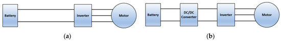
Figure 1.
Powertrains for electric vehicles: (a) Non-chopper powertrain; (b) Series-chopper-based powertrain [7].
There are several approaches to realizing energy savings with EVs, for example, (1) powertrain energy saving, including motor efficiency improvement, inverter efficiency improvement, and battery efficiency improvement; (2) mechanical energy saving, including Cd (aerodynamics) improvement, reduced friction between the wheel and the road, and mechanical transmission improvement (i.e., direct drive, gearless drive). In this paper, the authors concentrate on improving inverter efficiency. If a very high power density chopper is realized for this purpose, it can be installed between the battery and the inverter of any EV.
2. Proposed Chopper-Based Powertrain
2.1. Concept
To improve the efficiency of the powertrain, a very high-efficiency chopper, named the two-battery High-Efficiency Energy Conversion System (HEECS), was previously proposed [6]. The HEECS chopper is based on a partial power conversion circuit. The highest efficiency of the HEECS chopper is 99.3% [6]. This study focuses on extending the single-charge driving range using the proposed HEECS chopper.
2.2. HEECS Chopper
The two-battery HEECS chopper is based on partial power conversion, as shown in Figure 2. The chopper consists of two batteries and one buck-type chopper. Figure 3 shows the operation of the HEECS chopper in three ranges of speed. In the low- and high-speed ranges, the duty ratio of the chopper is 0 and 1.0, respectively. In these two operating modes, the output current from the battery flows only through a switch and the inductor. Therefore, the chopper loss is very low. In the middle-speed range, the buck chopper works, and the HEECS chopper outputs variable voltage depending on the speed.
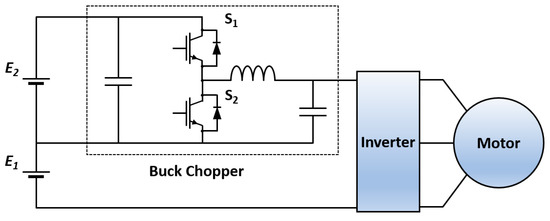
Figure 2.
Powertrain of the two-battery High-Efficiency Energy Conversion System (HEECS) chopper.
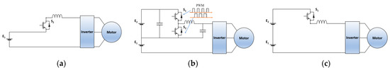
Figure 3.
Operation of the two-battery HEECS chopper: (a) Low-speed range; (b) middle-speed range; (c) high-speed range.
The output voltage VHEECS and efficiency ηHEECS are approximately expressed as
where E1, E2, d, P1, P2, and ηchop represent the voltage of E1, the voltage of E2, the duty ratio, the output power of E1, the output power of E2, and the efficiency of the chopper, respectively. Thus, the overall efficiency of the HEECS is higher than the efficiency of the chopper [5].
2.3. Freedom of Parameter Optimization
There is considerable freedom when choosing parameters for the optimization of the HEECS chopper-based powertrain. For example, any value can be ascribed to E1, E1 + E2, and the voltage gradient when the speed increases.
The switching loss of the inverter is proportional to the equation EI/6, where E is the DC link voltage and I is the inverter current referred to in Reference [7]. Thus, by changing the DC link voltage depending on the vehicle speed, energy savings can be realized in the inverter, assuming that the chopper loss is very small.
The DC link voltage E1 is kept constant in the low-speed range, and at a certain speed, the DC link voltage can be increased by the buck chopper until reaching E1 + E2. Then, over a certain high speed, it becomes constant. The parameters should be optimized in the following respects. (1) The switching loss in the low-speed range should be minimized by the best combination of E1 and speed when the buck chopper begins to work. (2) Depending on the tested driving mode cycle, the total energy savings should be maximized by the selection of the DC link voltage gradient as the speed increases. (3) Motor efficiency can be improved by the best Pulse Width Modulation (PWM) selection for a low ripple current. (4) The buck chopper efficiency also influences the overall efficiency optimization. (5) Other factors not mentioned here can also be varied. It is expected that we need plenty of time to optimize these parameters. Thus, in this paper, we investigate a simple strategy, which is mentioned later in Section 3.2, to empirically optimize the parameters.
3. Case Studies
In this section, using an EV selected from Reference [8], two types of powertrains—a non-chopper-type powertrain and HEECS chopper-based powertrain—are compared in terms of driving range extension.
3.1. Test Car Specifications
The driving resistances were determined from the characteristics of the vehicle described in Reference [6]. The case study in this paper focuses on driving range using simulations and experiments with the vehicle specifications listed in Table 1. This car is called “KANA”, and it is a test vehicle developed by the authors.

Table 1.
Specifications of the KANA vehicle.
3.2. Open-Loop Efficiency Map
Several experiments were executed to measure the steady-state efficiency of two types of powertrain: the non-chopper-type powertrain and the HEECS chopper-based powertrain. In this work, a motor test bench was used that has the same motor, inverter, and chopper as those used in the “KANA” vehicle. For the non-chopper-type powertrain, the duty ratio of the chopper was set to 1.0, and the output voltage was always E1 + E2. On the other hand, for the HEECS chopper-based powertrain, the output voltage was controlled according to the speed.
The output voltage VHEECS is expressed as
where v represents the motor speed [km]. For this case study, E1 + E2 = 350 V, and the in-wheel motor can rotate at 83 km/h without any additional control. Then, the flux-weakening control begins to work at rotations greater than 83 km/h, and the in-wheel motor can then rotate over that speed. Equation (3) was empirically selected, and the parameters E1 and the gradient that responds to the speed were determined by a trial-and-error approach in the 10–15-mode and JC08-mode driving test cycle.
The efficiency measurement points are as follows:
- Speed v [km/h]: 10, 20, 30, 40, 50, 60, 70, 80;
- Load torque Tm [Nm]: −60, −50, −40, −30, −20, −10, 10, 20, 30, 40, 50, 60.
Figure 4 and Figure 5 show efficiency maps of the non-chopper powertrain and the two-battery HEECS chopper-based powertrain. It is observed that the total efficiency is improved because the input voltage is controlled to be minimized in the HEECS chopper-based powertrain.
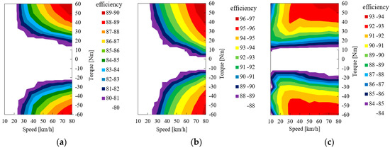
Figure 4.
Efficiency maps of non-chopper powertrain: (a) Total efficiency; (b) inverter efficiency; (c) motor efficiency.
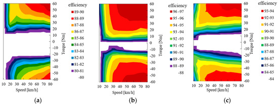
Figure 5.
Efficiency maps of HEECS chopper-based powertrain: (a) Total efficiency; (b) inverter efficiency; (c) motor efficiency.
3.3. Simulated Driving Range
The energy consumption in several driving cycle types was simulated using the measured efficiency maps in Figure 4 and Figure 5. The energy consumption was calculated using 10–15 driving cycle mode and JC08 driving mode as specified in the Japanese standard [9]. In addition, it was evaluated using a global harmonized test cycle, namely, WLTC class 3 [10].
In these cases, the torque command often exceeds 60 Nm, so the efficiency is fixed at the value of 60 Nm.
3.3.1. Comparison of Test cycles
In this section, several driving modes are explained. Figure 6 shows the driving patterns of the JC08 mode. Table 2 and Table 3 show the specifications of driving test cycles of JC08 mode, 10–15 mode, and WLTC class 3. In addition, Figure 7 shows the driving torque–speed map of each cycle. By referring to these maps, it is possible to understand the acceleration and deceleration for each mode’s cycle.
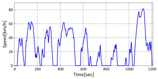
Figure 6.
Driving pattern of JC08 mode.
Table 2.
Specifications of 10–15 mode and JC08 mode.
Table 3.
Specifications of WLTC Class 3.
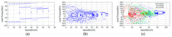
Figure 7.
Torque–speed maps of the driving cycles: (a) 10–15 mode; (b) JC08 mode; (c) WLTC mode.
The driving range of 10–15 mode is low speed and low torque, so it is intended for urban driving. JC08 mode is for a small high-speed range and high load torque range. WLTC mode is divided into three parts: Low, Medium, and High. So, the energy consumption can be evaluated according to the driving situation by using the WLTC.
3.3.2. Simulation Conditions
The driving resistances were calculated from the measured parameters of the vehicle described in Reference [8,11]. The total driving resistance torque is calculated as a function of the acceleration force Facc, the friction force Frol, and the aerodynamic force Fair, which are calculated by Equations (4)–(6), respectively. Since the vehicle has two front drive wheels, the load torque per in-wheel motor is equal to half of the driving resistance, and the rotation torque is calculated by Equation (7).
The motor output power is calculated as a function of the load torque Tm and motor angular velocity ωm. The required battery output is calculated using the efficiency map at the operating point. The efficiency ηtotal is linearly interpolated from four measurement points around the operating points. The battery energy consumption in powering Wbat_p and regenerating Wbat_r is calculated by Equations (8) and (9), respectively. The total energy consumption is obtained by Equation (10).
3.3.3. Simulation Results
Table 4 shows the energy consumption results of the simulation. It is observed that the energy consumption of the HEECS chopper-based powertrain is 5.1% lower in JC08 mode and 6.0% lower in 10–15 mode compared with the energy consumption of the non-chopper powertrain. In WLTC mode, it is observed that the reduction ratios are 10.3% in low mode, 3.8% in middle mode, 1.2% in high mode, and 4.1% in total.
Table 4.
Simulation results of energy consumption in test cycles.
From Figure 4a and Figure 5a, the efficiency of the HEECS chopper powertrain is improved in the low-speed range compared with that of the non-chopper powertrain.
The speed range of the 10−15 driving cycle and WLTC low mode is intended for city driving, and that of the others are for a short high-speed driving range. From Table 4, it is observed that the proposed chopper-based powertrain has higher energy savings in 10–15 mode and WLTC low mode than in the other driving mode. Thus, it seems that the chopper-based powertrain is more suitable for urban driving than it is for high-speed driving.
3.4. Experiments with the Motor Test Bench
Experiments were conducted to measure the energy consumption of the powertrain using a motor test bench.
3.4.1. Experimental Conditions
In the hardware simulator (test bench) of the powertrain, the in-wheel motor, inverter, and two-battery HEECS chopper were identical to those used in the simulations reported in Section 3.3 [11]. The output voltage of the HEECS was controlled so that it was equal to Equation (3), and the non-chopper powertrain was always equal to the constant value E1 + E2. The load torque was given by the load motor connected to the in-wheel motor, and the torque was changed to be equal to Equation (7) every 1 s for all driving conditions. The smooth transient of the mode change from low constant voltage to chopper operation and so on needs “intermittent pulse density control”, which is published in Reference [12].
Four kinds of driving cycle tests were selected: 10–15 mode, JC08 mode, WLTC low mode, and WLTC middle mode. Before measuring the energy consumption, the test bench was warmed up for 60 min.
3.4.2. Experimental Results
Table 5 shows the experimental results. It is observed that the energy consumption of the HEECS chopper-based powertrain is reduced by 6.3% in 10–15 mode and 5.3% in JC08 mode compared with the energy consumption of the non-chopper powertrain. In WLTC mode, it is observed that the reduction ratios are 6.4% in low mode and 1.9% in middle mode. In 10–15 mode and JC08 mode, these energy-saving ratios are almost equal to the data in the simulation results in Table 4. On the other hand, the experimental results in WLTC mode are different from the simulation results because, in the simulation, the efficiency was fixed when Tm > 60 Nm. The torque range of WLTC mode is very large and often exceeds Tm > 60 Nm, so calculation errors occurred in the application of Equations (8) and (9).
Table 5.
Experimental results of energy consumption in test cycles.
However, it is confirmed that the energy consumption was reduced on the basis of comparing the chopper-based powertrain with the non-chopper powertrain.
3.5. Discussion
In the experiments using the motor test bench, because of the current limit of the inverter, the steady-state maximum torque output is limited to 60 Nm. In a very short transient period, the maximum torque of 200 Nm is observed; however, the efficiency can be measured only in the steady-state condition. Thus, we cannot measure the efficiency of the system over 60 Nm with the present hardware, but we can run the WLTC-middle driving cycle in the experiments.
In our simulation using the measured efficiency data, if the driving condition has a relatively low-speed and low-torque range (10–15 mode and JC08), the estimated consumption data are very close to the experimental data.
On the other hand, if the driving condition has a relatively high-speed and high-torque range (WLTC-middle), the estimated consumption data are smaller than the value in the experimental data because the measured 60 Nm torque condition is used for all cases in which the 60 Nm torque range is exceeded. However, even in the WLTC-middle driving cycle, the energy consumption in the low-speed and low-torque range is well estimated in the simulation. As a result, there is an error between the total energy consumption from the simulation and that from the experiment, and this error becomes larger when the total energy consumption in the higher-speed and higher-torque range becomes larger. This tendency is observed in Table 4 and Table 5.
In addition, for the consumed energy-saving effect, it is observed from Figure 4a and Figure 5a that a large part of the saved energy occurs in the relatively low-speed region. Thus, the energy-saving effect of the 10–15 and JC08 driving cycle tests is well estimated in the simulation, but in the WLTC driving test, the effect becomes relatively small when the total energy consumption is shifted to the high-speed range. For example, the energy saving ratios from the simulation and experiment are 6.0% and 6.3% in 10–15 mode and 5.1% and 5.3% in JC08 mode. These values become 10.3% and 6.4% in WLTC-low and 3.8% and 1.9% in WLTC-middle driving cycles.
4. Conclusions
First, the steady state of the HEECS chopper-based powertrain was measured using a motor test bench. Second, several kinds of driving mode tests were simulated using the measured data. It is observed that the energy consumption is reduced by 5.1% in JC08 mode, 6.0% in 10–15 mode, 10.3% in WLTC low mode, 3.8% in WLTC middle mode, and 1.2% in WLTC high mode for this powertrain. However, the measured efficiency in the steady state is limited to a torque range under 60 Nm; thus, these simulation results have inevitable errors depending on the driving test cycle. Third, using the motor test bench, driving cycle experiments were executed, and the energy-saving improvement is experimentally confirmed. The energy-saving ratio is 6.3% in 10–15 mode, 5.3% in JC08 mode, 6.4% in WLTC low mode, and 1.9% in WLTC middle mode.
The energy savings in the low-speed range are significantly improved compared with the non-chopper powertrain. Thus, the proposed HEECS chopper-based powertrain is more suitable for a relatively low-speed range, i.e., urban driving, than it is for a high-speed range driving, i.e., highway driving.
Author Contributions
Conceptualization, A.K.; data curation, A.T.; analysis, A.T. and T.I.; validation, A.T. and T.I.; investigation, A.T. and T.I.; methodology, A.K.; resources, A.T. and T.I.; project administration, A.K.; writing—original draft preparation: A.K.; writing—review and editing, A.T., T.I. and A.K.
Funding
This research was funded by the Japan Society for the Promotion of Science, grant number 17H06147.
Conflicts of Interest
The authors declare no conflict of interest.
References
- Chopra, S.; Bauer, P. Driving range extension of EV with on-road contactless power transfer A case study. IEEE Trans. Ind. Electron. 2013, 60, 329–338. [Google Scholar] [CrossRef]
- Tenner, S.; Guther, S.; Hofmann, W. Loss Minimization of Electric Drive Systems Using a DC/DC Converter and an Optimized Battery Voltage in Automotive Applications. In Proceedings of the IEEE Vehicle Power and Propulsion Conference, Chicago, IL, USA, 6–9 September 2011; pp. 1–7. [Google Scholar]
- Nissan (n.d.). NISSAN LEAF. Available online: https://www3.nissan.co.jp/vehicles/new/leaf.html (accessed on 29 January 2019).
- Pavlovsky, M.; Tsuruta, Y.; Kawamura, A. Bi-directional buck/boost dc-dc converter with ultra high efficiency based on improved SAZZ topology. In Proceedings of the Energy Conversion Congress and Exposition, ECCE 2009, San Jose, CA, USA, 20–24 September 2009; pp. 1783–1790. [Google Scholar]
- Hosoyamada, Y.; Takeda, M.; Nozaki, T.; Motoi, N.; Kawamura, A. High Efficiency Series Chopper Power Train for Electric Vehicles Using a Motor Test Bench. IEEJ J. Ind. Appl. 2015, 4, 460–468. [Google Scholar] [CrossRef][Green Version]
- Tsuruta, Y.; Kawamura, A. Principle verification prototype chopper using SiC MOSFET module developed for partial boost circuit system. In Proceedings of the IEEE Energy Conversion Congress and Exposition (ECCE), Montreal, QC, Canada, 20–24 September 2015; pp. 1421–1426. [Google Scholar]
- Hoft, R.G. Semiconductor Power Electronics; Springer: Dordrecht, The Netherlands, 1986; 324p. [Google Scholar] [CrossRef]
- Kawamura, A.; Guidi, G.; Tsutsuki, S.; Watanabe, Y.; Tsuruta, Y.; Motoi, N. Experimental Data Analysis on Total Driving Performance of Series Chopper Based EV Power Train. In Proceedings of the Annual Conference of the IEEE Industrial Electronics Society (IECON), Melbourne, Australia, 7–10 November 2011; pp. 1348–1353. [Google Scholar]
- TRIAS (Traffic Safety and Nuisance Research Institute’s Automotive Type Approval Test Standards) 5-10-2008; National Traffic Safety and Environment Laboratory: Tokyo, Japan, 2008.
- TRIAS (Traffic Safety and Nuisance Research Institute’s Automotive Type Approval Test Standards) 08-002-02; National Traffic Safety and Environment Laboratory: Tokyo, Japan, 2008.
- Tamura, A.; Kobayashi, K.; Tsuruta, Y.; Kojima, K.; Obara, H.; Kawamura, A. Range Extension of Electric Vehicles by Two Battery HEECS Chopper based Power Train. In Proceedings of the IEEE ECCE2017-CINCINNATI-OHIO, Cincinnati, OH, USA, 1–5 October 2017; pp. 4488–4492. [Google Scholar]
- Tamura, A.; Ishibashi, T.; Umihara, T.; Tsuruta, Y.; Obara, H.; Kawamura, A. Intermittent Pulse Density Modulation of Two Battery HEECS Chopper for Electric Vehicles. In Proceedings of the IECON2018, Washington, DC, USA, 21–23 October 2018. [Google Scholar]


© 2019 by the authors. Licensee MDPI, Basel, Switzerland. This article is an open access article distributed under the terms and conditions of the Creative Commons Attribution (CC BY) license (http://creativecommons.org/licenses/by/4.0/).