Abstract
To improve the efficiency of electric vehicles (EVs), a planetary two-speed transmission is proposed, which consists of a brushless direct current (BLDC) motor, a turbo-worm reducer, two multi-disc wet brakes, and a Simpson planetary gearset. Based on the devised electronic actuator for shifting, the rotation direction of the BLDC shaft determines the gear ratio of the transmission. For acquiring smooth shift, the state-space equations with control variables of transmission are derived, and a three-stage algorithm is suggested. During the brake engagement process, the optimal control strategy has been developed using linear quadratic regulator control, considering the jerk and friction work of the brake. The simulation results show that the proposed optimal control strategy could reduce the slipping friction work of the brake and improve the shifting quality of EVs. The optimal control trajectory of the BLDC motor was conducted on the electronic shifting actuator bench test.
1. Introduction
Electric vehicles (EVs) are increasingly used due to internal combustion engine-related air pollution and global warming. Compared with traditional powertrain system, the driving motor of an EV is able to generate constant torque at low speed and constant power at high speed, which agrees with the requirements of EVs [1]. The cruising ranges of EVs are extended by increasing the energy-storage capacity or improving the efficiency of the transmission system. However, most EVs are equipped with a fixed ratio gearbox. For acquiring high speed and acceleration, the power and torque of driving motor need to be high enough.
Reported studies have found that the gear ratio and shift schedule optimization strategies are related to the efficiency of the EVs equipped with transmissions [2,3,4,5]. In the paper, it is shown that the EV with a two-speed transmission has better performance than a fixed ratio gearbox, in terms of acceleration time, maximum speed, and energy economy [6]. Eberleh et al. found that the efficiency in common driving cycles could be increased when a motor coupled with a two-speed transmission is compared to a motor equipped with a fixed ratio gearbox [7]. Sorniotti and Subramanyan compared a conventional single-speed transmission layout, a two-speed layout, and a continuously variable transmission (CVT) layout 1. The two-speed transmission system showed significant advantages over the single-speed layout and CVT layout. Therefore, the EVs, coupled with a two-speed transmission, will become a development trend for enhanced powertrain efficiency.
The layout and optimal shift control of the adoption of the two-speed transmission system for EVs have been performed. At present, there are several types of two-speed transmissions including manual transmissions (MTs) [8], automated manual transmissions (AMTs) [9,10,11], dual-clutch transmissions (DCTs) [12,13,14,15], and automatic transmissions (ATs) [16]. Sorniotti and Pilone et al. added a one-way sprag clutch to the traditional MT, although it is difficult to shift seamlessly due to the MTs’ layout [17]. Two clutches are used in a DCT for removing the torque interruption during gear-shifting [18,19]. Ruan et al. [20] developed three case layouts of powertrain system for EVs, and they found that CVT can reduce energy consumption, and manufacturing cost. Actually, the stability of the steel strip restricts the development of the CVT in high power EVs. Shin et al. [16] presented a two-speed Simpson type planetary gearbox. The result of the vibration test, noise test, and transmission efficiency test was obtained, which meet the demand. As we all know, the planetary gear sets system with torque converter changes gear ratios smoothly [21]. The multiple plates clutch with the hydraulic system is often selected as a clutch for planetary transmission. However, the hydraulic system is not available in EVs. Considering the stability and accuracy of the controller, the motor-driven mechanism for gear-shifting is suitable for drive units for EVs, which permits controlling the pressure of the wet clutch with high accuracy. Therefore, it is necessary to develop an electronic actuator for planetary gear sets for a swift and smooth shift.
For acquiring smooth shifting, researches have proposed optimization algorithms for different types of transmissions [22,23,24,25]. Alizadeh et al. [9] designed an observer to estimate the frictional torque transferred during gear-shifting, and the results demonstrated that the feedback control configuration is suitable to improve the shifting performance of the closed-loop system. The experimental study of the transient shift behavior of an EV coupled DCT was undertaken [12]. Using torque based control techniques, it is possible to achieve high-quality gear-shifting. The authors utilized the torque of the powertrain as an optimal shifting control target through deriving dynamic equations. Roozegar and Angeles used polynomial transition functions as the strategy of the angular velocities based on the calculus of variance [26]. The torques of the driving motor and the clutches during gear-shifting were calculated applying the polynomial transition functions based on the motor specifications considering acceleration and jerk. The optimal torque of the motor was proposed by a linear feed-forward control for inverse AMTs, and a mathematical model was developed for multispeed transmissions in EVs [27,28]. The results showed that the dynamic model of the planetary system could be utilized for optimal shifting control with the response of the transmission. Rahimi et al. designed an observer based on the back-stepping control following the optimal trajectory for minimizing shifting time [29,30]. The shifting controller was designed with the separate discrete-time PID, which improves shifting quality even in the condition of disturbances utilizing a genetic algorithm and trial-and-error [31].
This paper shows that the high fidelity mathematical model and adapted algorithm of a gear-shifting actuator could guarantee the performances of shifting. This paper presents the dynamic model of a two-speed transmission, which includes two brakes and an electronic shifting actuator and develops a three-stage (two sliding friction stages and gap stage) gear-shifting control algorithm. The linear-quadratic optimal control is applied to determine the optimal torque for shifting the motor during sliding friction stages. The speed trajectory of the BLDC motor for shifting was found during the shifting process. The remainder of this paper is arranged as follows. Section 2 describes the topology and dynamic model of the proposed shifting actuator. Section 3 presents the deducing process of the optimal controller for gear-shifting using the LQR (linear quadratic regulator) method. The simulation results in AMESim and discussions are presented in Section 4. A conclusion is shown in Section 5.
2. Statement of Planetary Two-Speed Transmission
The two-speed planetary gear system with electronic actuators was established, as shown in Figure 1. This transmission has a Simpson planetary gearset and two brakes which connect with the ring gears, and the detailed parameters are shown in the Table 1. Based on this structure, the speed ratio was around 2, which achieved a smooth shift easily. When brake 1(B1) engaged, the ring gear of the left planetary system became static, and the planetary system became a differential gear train. When brake 2(B2) engaged, the ring gear of the right planetary system became static, and the gear ratio was the larger one.
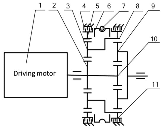
Figure 1.
Schematic diagram of the planetary two-speed transmission. 1-driving motor; 2-sun gear in planetary system 1(S1); 3-carrier in planetary system 1 (C1); 4-brake 1(B1); 5-ring gear in planetary system 1 (R1); 6-worm shaft; 7-worm gear; 8-ring gear in planetary system 2 (R2); 9-carrier in planetary system 2 (C2); 10-sun gear in planetary system 2(S2); 11-brake 2(B2).

Table 1.
Parameters of the planetary system.
2.1. Planetary Gear Sets Modeling
According to the Lagrange method, the dynamic model of planetary gear sets is built based on the structure of the two-speed transmission, which includes two sets of planetary gears shown in Figure 2. Considering the generalized meshing equations, there are four constraint equations for the planetary systems, where represents the angle of the S1 and S2, represents the angle of C1 and R2, represents the angle of pinions in the left planetary, represents the angle of R1, represents the angle of C2 and represents the angle of pinions in the right planetary. We assume that there is no sliding between the sun gears and pinions and pinions and ring gears in these two planetary system.
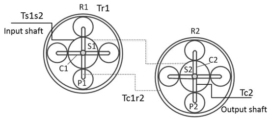
Figure 2.
The Simpson planetary gearset.
The system has two degrees of freedom (DOF) and (, ) is chosen as the set of independent coordinates. Using the constraint equations, it is easy to find the relationship between the remaining coordinates and the independent coordinates.
where .
Based on the kinetic energies equations in terms of each gear, the virtual work of the system with the virtual displacements of the independent coordinates is derived as
where the applied torque on the gears due to friction elements is , , , . The equation of dynamics and constraint for two-speed transmission are written in matrix form.
It can be seen that the , , , and are constants from Equation (5) and are almost always non-singular. Therefore, the input and output angular accelerations have a linear relation with the friction torque of brakes and input torque.
3. Shifting Actuator
The gear-shifting actuator proposed in this paper consists of a BLDC motor, enveloping worm, worm gear with a screw surface, guide mechanism, and two brakes. Compared with hydraulic actuators for shifting, the electronic shifting system has the following advantages: simple structure, comfortable deployment, and fast response. This electronic actuator with a worm gear, which enables large reduction ratios to be achieved, presses the plates of the brake for changing the gear ratio by the BLDC motor. Due to the self-locking characteristics of the worm system, the BLDC motor avoids turning on after the brake is engaged. The BLDC motor drives the worm shafts which rotate following the desired direction, and the range of the worm gear is around 120 degree. The worm gearing and guide mechanisms with helicoid implement translational motion instead of rotation, and it pushes the plates of the brakes for shifting. The structure of the electronic shift system is shown in Figure 3, but the pistons of the brakes are replaced by the guide mechanism with a screw surface.
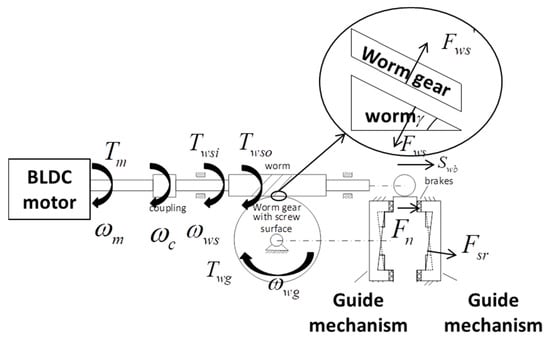
Figure 3.
Structure diagram of an electronic actuator.
3.1. The BLDC Motor Used for Shifting
The BLDC motor drives the worm pairs through a coupler, which overcomes the moment of inertia and the moment of friction. The dynamic equation of the BLDC motor displays as follows:
where is the inertia of the rotor, is the angular velocity, is the output torque of the BLDC motor, is the torque of the load, and is the damping coefficient.
3.2. Coupling Model
An elastic coupler connects the output shaft of the BLDC motor and worm shaft, and the torque of the motor transfers to the shaft of the worm by overcoming the inertia moment of the coupler. The torque can be calculated as
where is the input torque of the worm shaft, is the inertia of the coupler, and is the angular speed of the coupler.
3.3. Worm Gearing with Screw Surface Model
The worm gear with screw surface not only converts the rotation to translation, but the translational motion moves along the screw surface to change the displacement accurately. Thus, the guide mechanism plays the role as a piston to change the working conditions of the brakes. The equivalent dynamic equation of worm gearing system can be presented as follows:
where is the output torque of the worm shaft, is the inertia of the worm shaft, is the angular speed of the worm shaft, is the input torque of the worm gear, is the ratio of the worm gearing, , is the angular speed of the worm gear, and is the transmission efficiency of the worm system.
Analyzing the dynamical performances of the worm gear, the equation of translation along the axis is presented as follows:
where is the mass of the worm gear, is the axial displacement of the worm gear, is the support force by the worm, is the lead angle of the worm system, is the normal force on plates of the brake, is the support force by the guide mechanism, is the spiral angle between the worm gear and guide mechanism, and is the axial damping coefficient.
The rotate motion of the worm gear is represented by following dynamical equation.
where is the inertia of the worm gear, is the angular acceleration of the worm gear, is the driving torque of the worm gear, is the friction torque between the worm gear and friction plates, is the equivalent radius of the friction plates, and is the damping coefficient of the rotation motion.
Since the worm gear contacts with guide mechanism invariably, the geometric constraint between the rotation motion and translation motion is stated by the following equation, which is related to the screw pitch and lift range. The dynamical equation of worm gear could deduce by the mentioned Equations (10)–(12).
3.4. Modeling of Multi-Disc Wet Brakes
The guide mechanism driven by the worm gear presses the friction plates to shift gears. The force of friction plates is analyzed in the following:
where is the mass of the friction plates, is the displacement of the plates, and is the damping coefficient. When the guide mechanism is not in contact with friction plates, the support force is zero. While the guide mechanism presses the plates, the static friction torque is shown as:
where is the coefficient of the kinetic friction coefficient of static friction, is the number of plates, and and are the radius of external diameter and inner diameter, respectively. The friction plates are copper-based, and the coefficient of kinetic friction is 0.06–0.08, and the maximum coefficient of static friction is 0.1–0.13.
The model of the brake considers the change in the coefficient of friction in off-going states and on-coming states, but the heat loss during sliding mode and the friction resistance by oil stickiness are neglected. Since the normal pressure of plates is difficult to measure during shifting, the displacement of the guide mechanism could be used to judge the state of the brake.
4. Optimal Trajectories in the Gear-Shifting Process
The proposed optimal controller for gear-shifting is elaborated in this section. Assuming fixed drag torque during shifting, the driving torque is decided by the angle of acceleration pedal. According to the indexes of shifting quality, the jerk and sliding friction work, the performance index function is designed by the state equations described in Section 2.1. The optimal quadratic control is applied to obtain the shifting controller.
4.1. Problem Statement of Gear-Shifting
Based on the structure of an electronic shifting actuator, the shifting process includes brake off-going stage, gap stage, and brake on-coming stage. Since there is no pressure applied on the plates, the friction torques of B1 and B2 remain zero during the gap mode, , . However, friction heat is produced by the plates during the brake off-going stage and on-coming stage. The friction works of brakes are and when B1 remains in sliding mode. During B2 working in the off-going stage and on-coming stage, the torques of friction of B1 and B2 are and , respectively. Therefore, the brake off-going stage and on-coming stage take a long time for smooth shifting, and the gap stage should take a short time for avoiding interruption. The friction torque of the brakes during the off-going stage and on-coming stage are calculated by Equation (14), which corresponds to the torque of the BLDC motor, given the parameters of the brake and support force of the guide mechanism. To improve the shifting quality and reduce shifting time, the performance indexes include the friction work of the brakes and jerk of EVs. Building the quadratic optimal controller, the optimal trajectory of torque for brakes, and , are obtained during shifting.
To improve the shift quality, the optimal quadratic control would be applied for the off-going stage and on-coming stage. During shifting, the torque of the driving motor changes in different stages. Then the driving motor works following the speed closed-loop and the two-speed transmission begins a down shift when the speed increases to the objective value . The driving motor operates by direct torque close-loop control after shifting. The control strategy of the driving motor is shown in Figure 4a, and Figure 4b shows the speed control strategy of the BLDC motor during shifting.
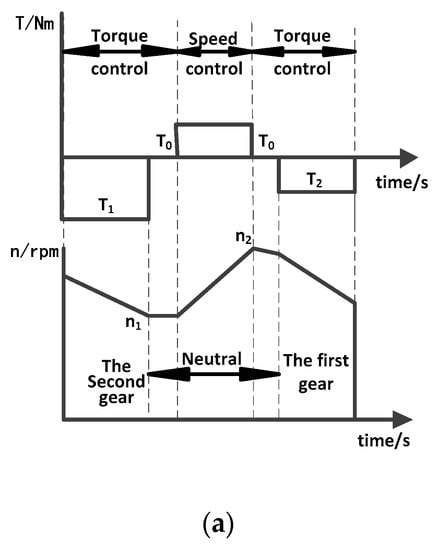
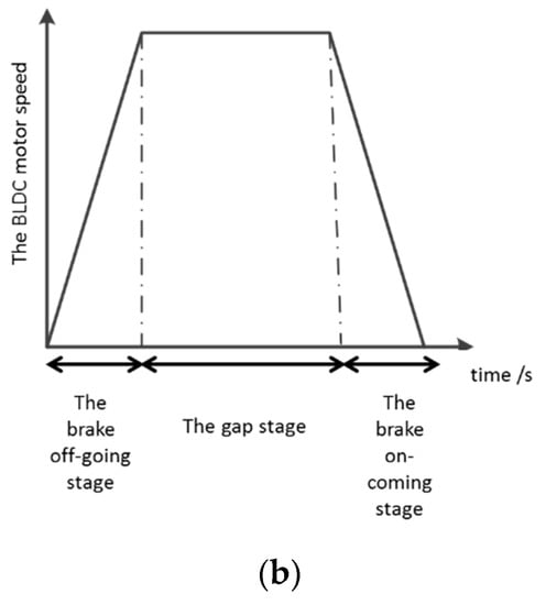
Figure 4.
Ideal curve. (a) States of the driving motor; (b) States of the brushless DC (BLDC) motor.
Generally, the performance indexes of brake consist of jerk and friction work, which influence the shifting quality and the work-life of the brakes. The value of the jerk would make it uncomfortable for passengers, and it also has an adverse effect on the powertrain system. Therefore, the jerk during shifting should be in a certain range, which is given as
where
.
To evaluate the jerk during shifting, is the performance index, which is represented by , where is the time of shifting. In addition, the friction work has a relationship with the work-life of the brakes, which is expressed as
where is the time of B1 for off-going, is the time of B2 for on-coming, and is the angular speed of the plates. Since there is a trade-off between the friction work and jerk during shifting, the expression of the comprehensive evaluation index can be represented as
where is a weighting coefficient, (). When is a large value, it is shown that the jerk takes a greater proportion during shifting, and it is easy to balance the proportion of friction work and jerk by tuning the coefficient. With regard to the weighting coefficient, , we tune the coefficient to make the maximum values of the integral of the jerk during shifting close to the value of the friction work.
4.2. Optimal Trajectory Control for Brakes
We set the state variables as and control variable as , where the state variables are presented by and control variable is given as . Therefore, the state equation could be expressed by , where is the coefficient matrix of the state variables, is the coefficient matrix of control variables and is interference matrix which depends on the torque of the driving motor and the resistance torque of the vehicle. Because the matrix is a non-singular matrix, the system is completely controllable.
4.2.1. The B1 Off-Going Stage
When B1 works in the off-going stage, the coefficient matrix of the state equation could be deduced by Equation (5), where
, , .
Because the matrix is a non-singular matrix, the system is completely controllable. The cost function is selected as
The linear-quadratic function can be expressed by , where the coefficient is and , and the designed Hamilton’s function is where is the Lagrange multiplier. When the shifting ends, the torque of the brakes should be 0, which means the terminal constraint is . Applying the principle of the minimum, the undetermined matrix is represented by based on the state of the final value and terminal constraints.
The objective for optimal control is to find the trajectory of friction torque for the brakes while minimizing the cost function. Since there is an interference matrix, the related matrix should be substituted into the equation . The solved control variables matrix is the optimal trajectory of friction torque for B1 during the off-going stage, and the process of the solving process is developed by a quadratic problem with disturbance.
4.2.2. The Gap Stage
The initial state and terminal state of the angular displacement of the BLDC motor output shaft, should follow the equations , , , .
The angular velocity of the motor tracks the optimal trajectory, which falls in the field of the calculus of variations. Researchers found that a quintic polynomial has good performances during shifting. Therefore, the quintic polynomial, , could be used as the optimal trajectory during the gap mode for the angular velocity of the BLDC motor. According to the constraints of initial and terminal states, the trajectory can be calculated by shown in Figure 5, where , , , and .
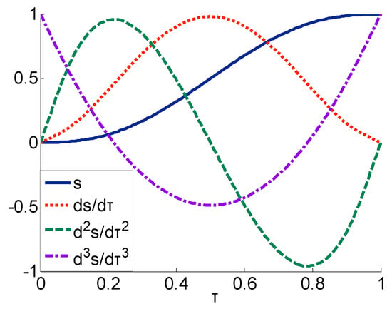
Figure 5.
Angular velocity in gap stage.
4.2.3. The B2 On-Coming Stage
The state equation of B2 is related to the dynamic function of planetary system P2, which is the same as the off-going stage. The state variables include , , and , and the control variable is , where the state variable is represented by and . The state equation is represented by
,
Because the matrix is a non-singular matrix, the system is completely controllable. According to the state matrix of the gear-shifting system, the optimal quadratic algorithm is applied to solve the trajectory of angular velocity for the BLDC motor. Since there is limited shifting time and computational capabilities, the trajectory can be fitted in different conditions, which are saved into the controller. The optimal trajectory can be found rapidly for real-time control.
For improving the shift quality, the optimal controller is designed based on quadratic optimization in this section for the down shifting process. As mentioned, there are three stages of shifting, and the linear-quadratic optimization is applied for the B1 off-going stage and B2 on-coming stage. The optimal control rate of the brakes is calculated by the quadratic algorithm, where is the feedback matrix and the gain of the controller.
where, is the elements of matrix P and is the parameter of matrix . Therefore, the control variable is given as . Following the main steps in Figure 6, the optimal trajectory of state variable could be obtained based on the Riccati matrix.

Figure 6.
Block diagram of an optimal controller for torque.
According to the optimal control algorithm, the controller diagram of electronic actuators is shown in Figure 6. Because the shifting process lasts only for a short time, it is impossible to solve the optimal trajectory by optimal quadratic control for the BLDC motor in that process. We calculated the parameters and in different shifting conditions, then they were fitted by a polynomial function. Those fit coefficients are saved in the control unit, which is used to fit the control policy during real-time control.
5. Simulation Results and Discussions
The dynamic model of EVs included the power system module, two-speed transmission, vehicle system, and driver-environment module, which were built in AMESim. The simulation model of EVs is shown in Figure 7.
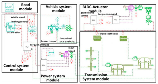
Figure 7.
Simulation model in AMESim.
With NEDC (new European driving cycle) drive cycle, the input of the model was the desired velocity of the vehicle, and the difference between the desired value and actual velocity exported the signals of acceleration and brake to the drive-environment module. In addition, the vector control method was applied to the driving motor by the PI control for angular velocity and torque. The states of the driving motor followed the desired torque and angular velocity by adjusting the current when the desired torque and actual torque were compared. The shifting controller of the BLDC motor was similar to the driving motor controller, and the PI control was used to track the objective curve for gear-shifting. Actual values of the powertrain system parameters are given in the Nomenclature. During the NEDC drive cycle, the simulation results showed that the velocity of the vehicle followed the desired value, which consisted of three times upshifts and downshifts.
5.1. Simulation Results Following NEDC Drive Cycle
Based on the simulation result with the NEDC drive cycle, we chose the first downshift, which is shown in Figure 8 by an arrow. Two control policies were applied during downshift, and one is named the original control, which used the BLDC motor speed fitted by the 3-4-5 polynomial mentioned in Section 4.2 during shifting. The other is the optimal control, which used the BLDC motor speed calculated by the optimal quadratic algorithm during the sliding stages and the shifting speed fitted by the 3-4-5 polynomial during the gap stage.
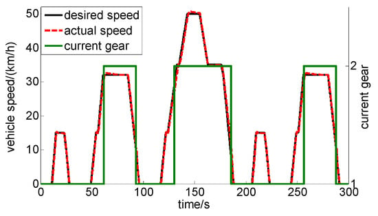
Figure 8.
Curves of gear number and angular velocity in the new European driving cycle (NEDC) driving cycle.
The BLDC motor speed follows the curve shown in Figure 4b, which is called the original control. The angular velocity followed the desired velocity based on the optimal quadratic algorithm when the simulation results of the original control and optimal control were compared. The controller of the BLDC motor had a swift response for tracking drive cycle. During the first down-shifting, the maximum jerk with the optimal controller reduced by 35%. As can be seen from Figure 8, the indexes of shifting quality have degraded gracefully, which led to acquiring a smooth and swift shift by tracking the desired trajectory.
5.2. Verification for Optimal Control Trajectory
According to the optimal angular velocity of the BLDC motor, the testbed of the actuator for shifting in our lab is shown in Figure 9. The output shaft of the BLDC motor connects the worm shaft, and the brakes system was neglected. In the test, the controller of the BLDC motor outputs optimized angular velocity, which was measured and shown on a computer. To drive the BLDC motor, the NI-CRIO was adopted as the main controller. LabVIEW was applied for communications between the computer and the NI-CRIO NI9401 boards for data acquisition. The test bench is shown in the Figure 10.
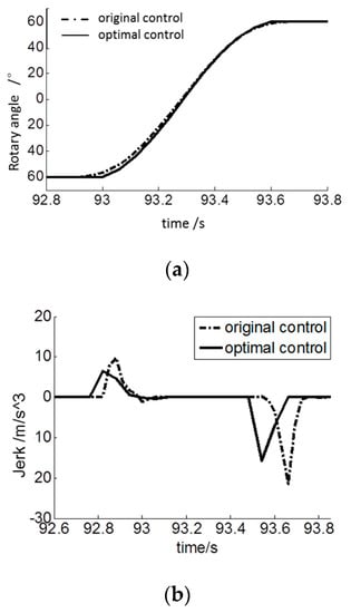
Figure 9.
Performances during down-shifting. (a) Optimal rotary angle during down-shifting; (b) Jerk with different controller during down-shifting.
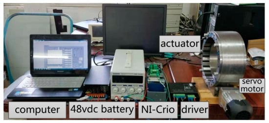
Figure 10.
The response test of the BLDC motor.
The speed regulation of the BLDC motor was adjusted by the PWM wave through LabVIEW. The duty ratio of the PWM wave had a linear relationship with the angular velocity after testing with different loads for the worm gear with a screw surface and the worm system. Tracking the optimal angular velocity of the BLDC motor, the velocity mode was adopted to follow the optimal trajectory obtained with the quadratic algorithm. Figure 11a,b represent the measured result of the actual rotary angle and the error between the actual angle and desired angle. Due to the inhibiting device for the actuator, the error did not exist at the end of the test. The maximum value of the error appeared at the end of the gap stage when the polynomial was applied, and it began to decrease along with the optimal torque control. Since the impact often happened in the off-going stage and on-coming stage, the maximum error of angular velocity failed to influence the shifting quality. The testbed verified the track effect with optimal quadratic control, and the response of BLDC motor achieved the real demands.
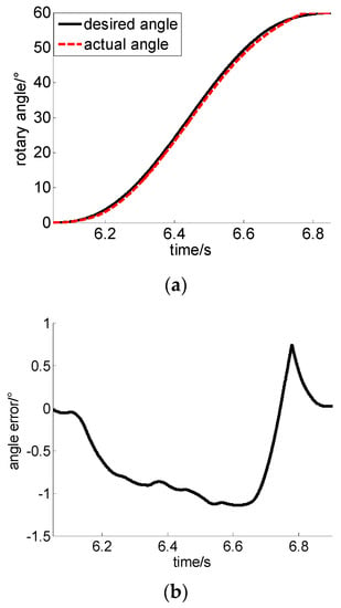
Figure 11.
Test results of the rotary angle of the BLDC motor. (a) Rotary angle; (b) Error of rotary angle.
6. Conclusions
Due to the complex structure of a clutch compared to brakes, a planetary two-speed transmission was designed for EVs, which was only coupled with brakes instead of clutches. The optimal control for the shifting process of an electronic actuator with a screw surface was proposed. By using the Lagrange method, the dynamics model of the designed planetary two-speed transmission and electronic actuator model were developed. Then, a three-stage optimal control algorithm was developed considering different stages for gear-shifting. The controllers of the BLDC motor were designed using quadratic optimal control theory for off-going and on-coming stages, and variation calculus for the angular velocity was applied in the gap stage. The optimal torque trajectories were proposed by using the quadratic method considering the external disturbances during sliding friction stages. When jerks and friction work of the brakes were compared, it was concluded that the optimal quadratic control for torque improved the shifting quality for EVs. Based on the test bench of the electronic actuator, experimental results demonstrated that the optimal trajectory could be achieved by the designed controller of the BLDC motor.
Author Contributions
Conceptualization, X.Z. and J.T.; methodology, X.Z.; software, X.Z. and J.T.; validation, X.Z. and J.T.; formal analysis, X.Z.; writing—original draft preparation, X.Z.; writing—review and editing, X.Z. and J.T.; funding acquisition, X.Z.
Funding
This work was financially supported by the Fundamental Research Funds for the Central Universities of China (Grant No. FRF-TP-18-036A1), the National Science Foundation for Young Scientists of China (Grant No. 51905031) and the National key research and development program (Grant No. 2018YFC0604402). The APC was funded by Grant No. FRF-TP-18-036A1.
Conflicts of Interest
The authors declare no conflict of interest.
Nomenclature
| i0 | final ratio |
| i2 | 1st gear ratio |
| i2 | 2nd gear ratio |
| η1 | efficiency of 1st gear |
| η2 | efficiency of 2nd gear |
| η0 | efficiency of reducer |
| J1 | rotational inertia of input shaft (kg m2) |
| J2 | rotational inertia of output shaft (kg m2) |
| JC | inertial of brakes (kg m2) |
| Jm | inertia of BLDC motor shaft (kg m2) |
| TCAX | maximum friction torque of brake (Nm) |
| Cds | friction coefficient of driving shaft |
| Kds | stiffness of driving shaft (Nm/°) |
| Cs | damp coefficient of driving shaft (Nm/(r/min)) |
| M | mass of EV (kg) |
| ρ | air density (Kg/m3) |
| A | area of windward (m2) |
| CD | coefficient of air resistance |
| F | coefficient of rolling resistance |
| R | radius of wheel (m) |
| α | slope (°) |
| g | acceleration of gravity (m/s2) |
| J0 | inertia of electronic actuator (kg m2) |
| J1 | inertial of powertrain system (kg m2) |
| J2 | inertial of wheel (kg m2) |
| ψfl | flux of driving motor (Wb) |
| Rs | stator resistance (Ω) |
| Ls | inductance of driving motor (H) |
| Lsd | inductance of d axis (H) |
| Lsq | inductance of q axis (H) |
| Imax | maximum effective current (A) |
| UDC | direct voltage (V) |
| P | pole pairs |
| R0 | the radius of external diameter (m) |
| R1 | the radius of inner diameter (m) |
| N | the number of plates |
| μs | the coefficient of kinetic friction |
| μd | the maximum coefficient of static friction |
References
- Sorniotti, A.; Subramanyan, S.; Turner, A.; Cavallino, C.; Viotto, F.; Bertolotto, S. Selection of the optimal gearbox layout for an electric vehicle. SAE Int. J. Engines 2011, 4, 1267–1280. [Google Scholar] [CrossRef]
- Sorniotti, A.; Holdstock, T.; Pilone, G.L.; Viotto, F.; Bertolotto, S.; Everitt, M.; Barnes, R.J.; Stubbs, B.; Westby, M. Analysis and simulation of the gearshift methodology for a novel two-speed transmission system for electric powertrains with a central motor. Proc. Inst. Mech. Eng. Part D J. Automob. Eng. 2012, 226, 915–929. [Google Scholar] [CrossRef]
- Zhang, Z.; Zuo, C.; Hao, W.; Zuo, Y.; Zhao, X.; Zhang, M. Three-speed transmission system for purely electric vehicles. Int. J. Automot. Technol. 2013, 14, 773–778. [Google Scholar] [CrossRef]
- Nicola, F.; Di Sorniotti, A.; Holdstock, T.; Viotto, F.; Bertolotto, S. Optimization of a multiple-speed transmission for downsizing the motor of a fully electric vehicle. SAE Int. J. Altern. Powertrains 2012, 1, 134–143. [Google Scholar] [CrossRef]
- Wu, G.; Zhang, X.; Dong, Z. Impacts of two-speed gearbox on electric vehicle’s fuel economy and performance. SAE Tech. Pap. 2013. Available online: https://www.researchgate.net/publication/289058822_Impacts_of_Two-Speed_Gearbox_on_Electric_Vehicle’s_Fuel_Economy_and_Performance (accessed on 6 August 2019).
- Gao, B.; Liang, Q.; Xiang, Y.; Guo, L.; Chen, H. Gear ratio optimization and shift control of 2-speed I-AMT in electric vehicle. Mech. Syst. Signal Process. 2015, 50, 615–631. [Google Scholar] [CrossRef]
- Eberleh, B.; Hartkopf, T. A high speed induction machine with two-speed transmission as drive for electric vehicles. In Proceedings of the Power Electronics, Electrical Drives, Automation and Motion (SPEEDAM 2006), Taormina, Italy, 23–26 May 2006; pp. 249–254. [Google Scholar]
- Ren, Q.; Crolla, D.A.; Morris, A. Effect of geared transmissions on electric vehicle drivetrains. In Proceedings of the ASME 2009 International Design Engineering Technical Conferences and Computers and Information in Engineering Conference, American Society of Mechanical Engineers, San Diego, CA, USA, 30 August–2 September 2009; pp. 959–966. [Google Scholar]
- Alizadeh, H.V.; Mousavi, M.R.; Boulet, B. Synchromesh torque estimation in an electric vehicle’s clutchless automated manual transmission using unknown input observer. In Proceedings of the 2015 IEEE Vehicle Power and Propulsion Conference (VPPC), Montreal, QC, Canada, 17 December 2015; pp. 1–5. [Google Scholar]
- Fang, S.; Song, J.; Song, H.; Tai, Y.; Li, F.; Nguyen, T.S. Design and control of a novel twospeed uninterrupted mechanical transmission for electric vehicles. Mech. Syst. Signal Process. 2016, 75, 473–493. [Google Scholar] [CrossRef]
- Gao, B.; Xiang, Y.; Chen, H.; Liang, Q.; Guo, L. Optimal trajectory planning of motor torque and clutch slip speed for gear shift of a two-speed electric vehicle. Journal of Dynamic Systems. Meas. Control 2015, 137, 061016. [Google Scholar] [CrossRef]
- Walker, P.; Zhu, B.; Zhang, N. Powertrain dynamics and control of a two speed dual clutch transmission for electric vehicles. Mech. Syst. Signal Process. 2017, 85, 1–15. [Google Scholar] [CrossRef]
- Gu, Q.; Cheng, X.S. Study on double-clutch transmission gear shift control based on optimal control theory. In Proceedings of the 2011 IEEE 18th International Conference on Industrial Engineering and Engineering Management, Changchun, China, 10 October 2011; pp. 629–634. [Google Scholar]
- Zhu, B.; Zhang, N.; Walker, P.; Zhan, W.; Zhou, X.; Ruan, J. Two-speed DCT electric powertrain shifting control and rig testing. Adv. Mech. Eng. 2013, 5, 323917. [Google Scholar] [CrossRef]
- Heap, A.H.; Sah, J.J.F.; Kaminsky, L.A. Control of engine torque during upshift and downshift torque phase for a hybrid powertrain system. U.S. Patent 9,008,926, 14 April 2015. [Google Scholar]
- Shin, J.W.; Kim, J.O.; Choi, J.Y.; Oh, S.H. Design of 2-speed transmission for electric commercial vehicle. Int. J. Automot. Technol. 2014, 15, 145–150. [Google Scholar] [CrossRef]
- Sorniotti, A.; Pilone, G.L.; Viotto, F.; Bertolotto, S.; Everitt, M.; Barnes, R.; Morrish, I. A novel seamless 2- speed transmission system for electric vehicles: Principles and simulation results. SAE Int. J. Engines 2011, 4, 2671–2685. [Google Scholar] [CrossRef]
- Cavina, N.; Corti, E.; Marcigliano, F.; Olivi, D.; Poggio, L. Control-Oriented Models for RealTime Simulation of Automotive Transmission Systems. Oil Gas Sci. Technol. Rev. díIFP Energies Nouv. 2015, 70, 67–90. [Google Scholar] [CrossRef][Green Version]
- Liang, Z. Reliability Analysis of Dual Clutch Transmission. Automob. Appl. Technol. 2016, 2016, 98–100. [Google Scholar]
- Ruan, J.; Walker, P.D.; Wu, J.; Zhang, N.; Zhang, B. Development of continuously variable transmission and multi-speed dual-clutch transmission for pure electric vehicle. Adv. Mech. Eng. 2018, 10, 1687814018758223. [Google Scholar] [CrossRef]
- Lazar, C.; Caruntu, C.F.; Balau, A.E. Modelling and predictive control of an electrohydraulic actuated wet clutch for automatic transmission. In Proceedings of the 2010 IEEE International Symposium on Industrial Electronics, Bari, Italy, 4–7 July 2010; pp. 256–261. [Google Scholar]
- Heijden, A.V.D.; Serrarens, A.F.A.; Camlibel, M.K.; Nijmeijer, H. Hybrid optimal control of dry clutch engagement. Int. J. Control 2007, 80, 1717–1728. [Google Scholar] [CrossRef]
- Dutta, A.; Ionescu, C.M.; De Keyser, R.; Wyns, B.; Stoev, J.; Pinte, G.; Symens, W. Robust and two-level (nonlinear) predictive control of switched dynamical systems with unknown references for optimal wet-clutch engagement. Proc. Inst. Mech. Eng. Part I J. Syst. Control Eng. 2014, 228, 233–244. [Google Scholar] [CrossRef]
- Ngo, V.; Hofman, T.; Steinbuch, M.; Serrarens, A. Optimal control of the gearshift command for hybrid electric vehicles. IEEE Trans. Veh. Technol. 2012, 61, 3531–3543. [Google Scholar] [CrossRef]
- Kum, D.; Peng, H.; Bucknor, N.K. Supervisory control of parallel hybrid electric vehicles for fuel and emission reduction. J. Dyn. Syst. Meas. Control 2011, 133, 061010. [Google Scholar] [CrossRef]
- Roozegar, M.; Angeles, J. The optimal gearshifting for a multi-speed transmission system for electric vehicles. Mech. Mach. Theory 2017, 116, 1–13. [Google Scholar] [CrossRef]
- Liang, Q.; Ren, L.; Zhao, H.; Gao, B.; Hong, C. Gearshifting Control of Battery Electric Vehicle with 2- Speed I-AMT Autimotive Engineering. In Proceedings of the 2013 China Automobile Engineering Conference, Beijing, China, 26 November 2013; pp. 1000–1003. [Google Scholar]
- Setiawan, Y.D.; Roozegar, M.; Zou, T.; Angeles, J. A Mathematical Model of Multispeed Transmissions in Electric Vehicles in the Presence of Gear-shifting. IEEE Trans. Veh. Technol. 2018, 67, 397–408. [Google Scholar] [CrossRef]
- Mousavi, M.S.R.; Pakniyat, A.; Helwa, M.K.; Boulet, B. Observer-based backstepping controller design for gear shift control of a seamless clutchless two-speed transmission for electric vehicles. In Proceedings of the 2015 IEEE Vehicle Power and Propulsion Conference (VPPC), Montreal, QC, Canada, 17 December 2015; pp. 1–6. [Google Scholar]
- Mousavi, M.S.R.; Boulet, B. Estimation of the state variables and unknown input of a two-speed electric vehicle driveline using fading-memory Kalman filter. IEEE Trans. Transp. Electrif. 2016, 2, 210–220. [Google Scholar] [CrossRef]
- Roozegar, M.; Angeles, J. A two-phase control algorithm for gear-shifting in a novel multispeed transmission for electric vehicles. Mech. Syst. Signal Process. 2018, 104, 145–154. [Google Scholar] [CrossRef]
© 2019 by the authors. Licensee MDPI, Basel, Switzerland. This article is an open access article distributed under the terms and conditions of the Creative Commons Attribution (CC BY) license (http://creativecommons.org/licenses/by/4.0/).