1. Introduction
The experience of rally competitions with Outlander PHEV has made us aware that the enhancement of motor cooling performance is essential to win the race. Rallies require driving of high speed, high torque, long period and long range. Such driving generates serious motor heating. To protect the motor materials, such as magnets or the insulation of copper coil windings, torque limitation is required at the upper limit of coil temperature. Once coil temperature exceeds the upper limit, torque is inhibited at limitation level, which results in deterioration of acceleration performance. This is why higher motor cooling performance plays the key role for the faster driving.
Beyond rally cars, higher motor cooling performance contributes greatly to mass-produced vehicles by the following two aspects:
Rated torque increase
Downsizing
First contribution is rated torque, which should be increased without negotiating the motor size. The rated torque is generally defined as the torque where motor cooling maintains thermal equilibrium so that a motor can operate continuously. Higher cooling performance enhances motor’s rated torque. Second is downsizing of a motor with realizing higher rated torque. Diameter of copper coil windings defines a motor size. Thinner windings increase its resistance that generates more heat. Enhanced cooling performance should absorb increased heat generated by thinner windings, which should realize downsizing of a motor.
Table 1 shows three methods of conventional motor cooling:
Air cooling
Oil cooling
Water cooling
First is air cooling, which is mainly utilized in train motors, not in the driving motors of electric vehicles except for some in-wheel motor cars [
1,
2]. Air cooling is superior to other methods in terms of the cost and the cooling uniformity; however its performance is the lowest among the three conventional cooling methods. Second is oil cooling, which has the best cooling performance since oil flowing into a motor housing cools a heat source directly [
3,
4]. Mitsubishi motors apply the oil cooling to the front motor of Outlander PHEV [
1,
5]; however, oil cooling compromises the cooling uniformity and the system cost. Moreover, it requires a water cooling system separately to cool an inverter. The final conventional method is water cooling, which is the most common method among electric vehicles [
6]. Mitsubishi motors apply water cooling to the driving motor of i-MiEV and the rear motor of Outlander PHEV [
1,
5]. In this method, water flows into a jacket installed in the housing and exchanges generated heat. It achieves better cooling uniformity and less system cost than oil cooling; however, its cooling performance is not effective as much as that of oil cooling.
2. Refrigerant Cooling
2.1. Concept
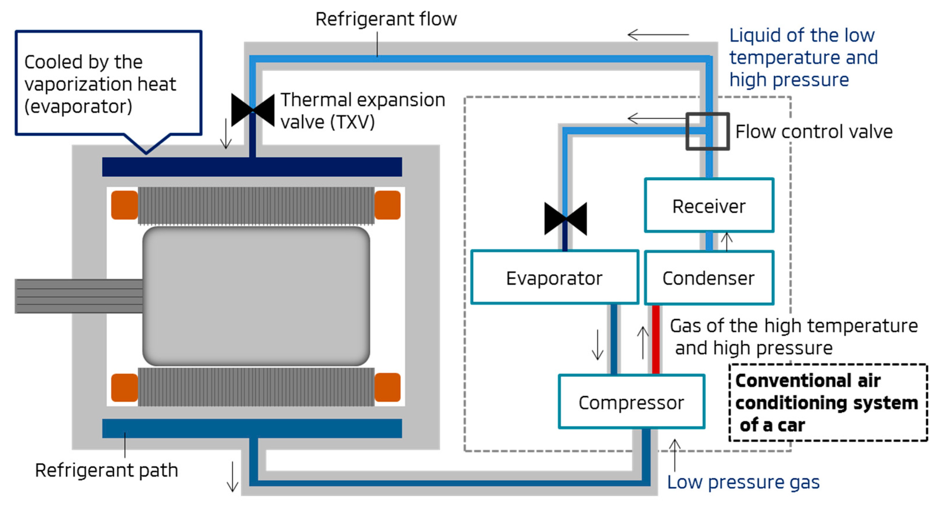
To enhance the conventional cooling performance, we have developed a new cooling method: refrigerant cooling. The refrigerant cooling system is connected with a car air conditioning (A/C) system in parallel as shown in
Figure 1. It uses a jacket for water cooling as refrigerant path that is installed in a motor housing. A thermal expansion valve (TXV) is attached at an inlet of the motor housing, at which liquid refrigerant evaporates to some extent. The rest of liquid refrigerant evaporates in the path absorbing heat from the motor. A compressor regulates its operation rate to control the cooling performance.
2.2. Expected Benefits
Three expected benefits from replacing water cooling system by refrigerant cooling are:
Fewer components for PHEV
Greater cooling uniformity
Higher cooling performance
First of all, integration of cooling systems with the A/C system should reduce components.
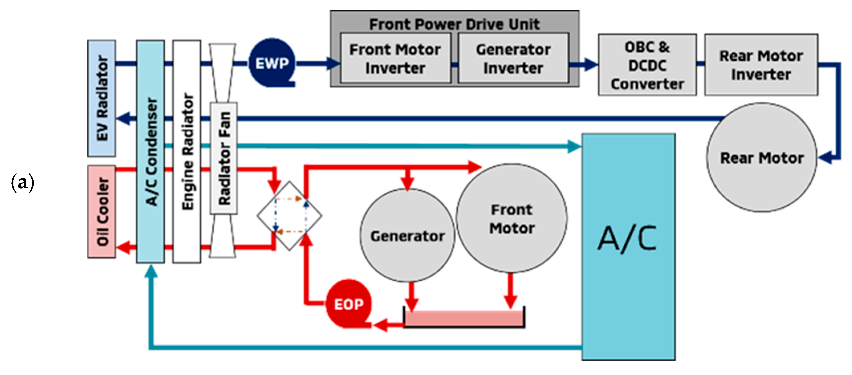
Figure 2a shows the current cooling system of Outlander PHEV. Four heat exchangers are located in the front of a vehicle: Two radiators (one for an engine not illustrated in
Figure 2 and another for water cooling of EV system); one oil cooler for oil cooling of the front motor and the generator; and one condenser for the A/C. If inverters and converter are integrated into the refrigerant cooling system referring to previous researches [
7,
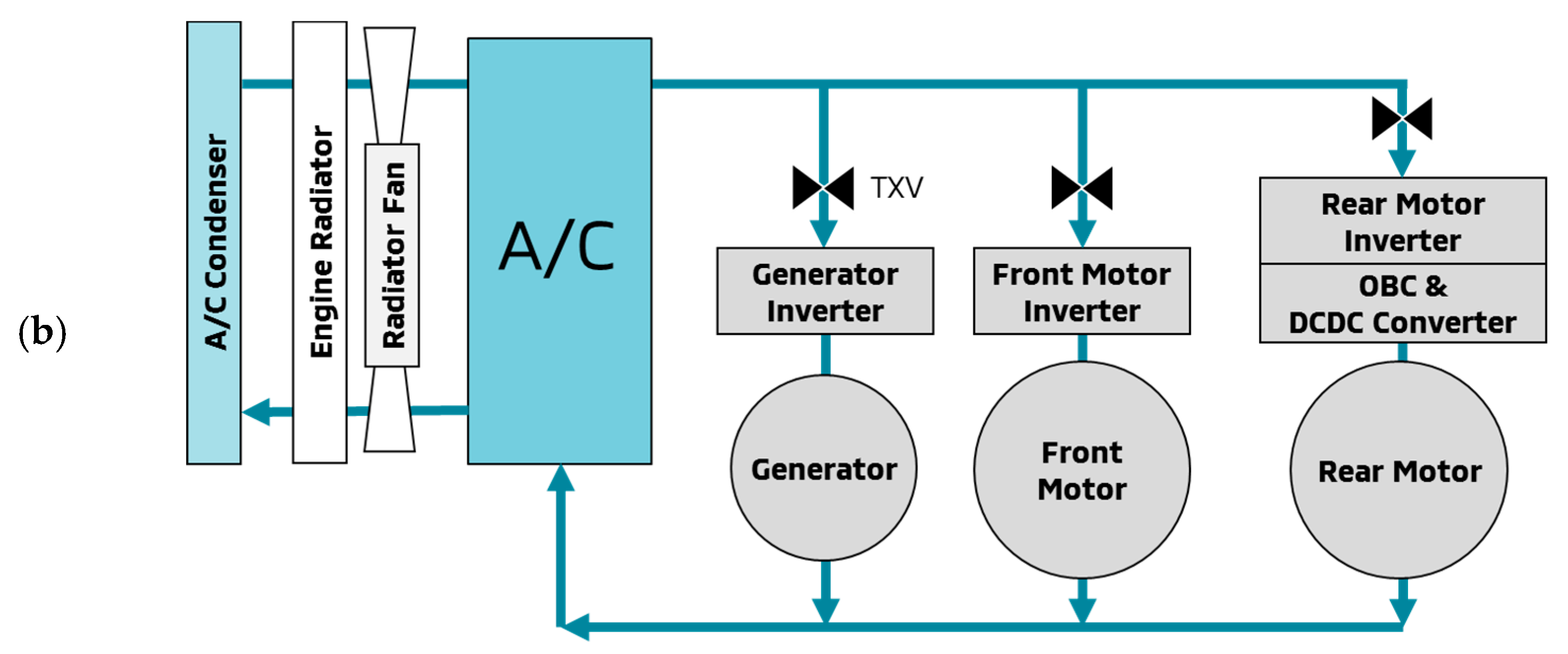
8], refrigerant cooling should reduce these four heat exchangers into two: A radiator for the engine cooling and a condenser for the refrigerant cooling as shown in
Figure 2b. The essentials to realize this ideal system are: The greater cooling ability of the compressor; the distribution control of refrigerant; and the compressor control to minimize the power consumption. Second is that the refrigerant cooling achieves greater cooling uniformity than oil cooling by letting refrigerant flow through the water jacket. The final benefit of the refrigerant cooling is higher cooling performance than that of water cooling. The study in this paper aims to verify the fact that the refrigerant cooling performance is higher than the water cooling through two approaches: simulation and experiment.
3. Simulation
Simulation shows that refrigerant cooling kept the coil temperature lower than water cooling. This simulation was performed on a one-dimensional model [
9,
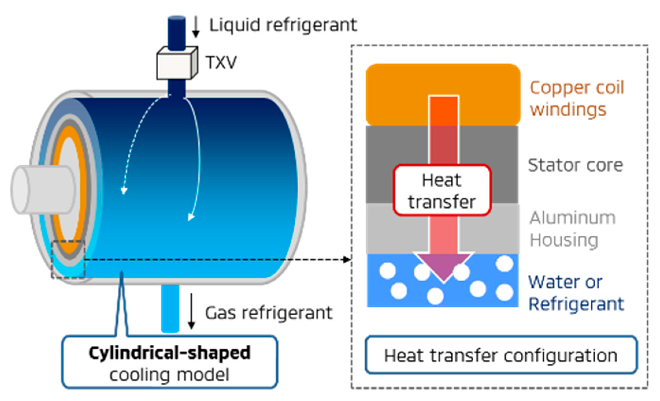
10]. The simulation used the same model for water cooling and refrigerant cooling. The model describes a motor cooling structure without an AC circuit. We introduced a cylindrical-shaped water jacket as shown in
Figure 3 to simulate the complicated water/refrigerant path. Heat generated by electrical current through copper coil windings is transferred to water/refrigerant path across the steal stator core and the aluminum housing. For refrigerant cooling, a TXV was attached at the inlet of the refrigerant path to let liquid refrigerant evaporate effectively. Based on the initial experimental conditions
Table 2 shows, we calculated the maximum temperatures at thermal equilibrium for water, refrigerant and copper coil windings. As a result, the coil temperature of refrigerant cooling was lower than that of water cooling by 48°C as shown in
Table 3.
4. Experiment
4.1. Procedure
The cooling performance was compared between water and refrigerant by using the same motor of the specification in
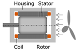
Table 4. All experiments started with water cooling as shown in
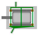
Figure 4a. A TXV was installed at the inlet of the water jacket as shown in
Figure 4b before experimenting refrigerant cooling. The refrigerant cooling experiment used the same motor as the water cooling experiment. The water jacket worked as the refrigerant path. In addition, the water circulation system was replaced by an A/C system. Compressor regulated its operation rate to control the refrigerant cooling performance. The compressor kept operating until the motor surface temperature declined to a target temperature. Note that the target temperatures for refrigerant cooling were set at 0, 10, and 20 °C. The compressor stopped its operation when the motor surface temperature was lowered below the target temperature. Three experiments were performed as shown in
Table 5.
In experiment 1, the motor temperature, which was operated at rated torque for 30 min, was measured.
In experiment 2, new rated torque was estimated when water cooling was replaced by refrigerant cooling.
In experiment 3, operation time at the maximum torque was measured.
4.2. Results and Discussion
4.2.1. Experiment 1
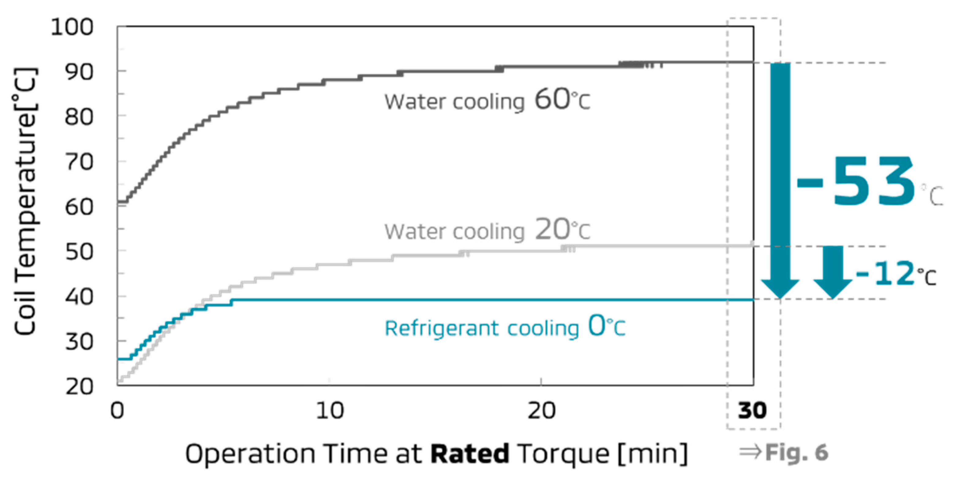
Figure 5 shows that refrigerant cooling kept the coil temperature lower than water cooling. Comparing water cooling of 60 °C and refrigerant cooling of 0 °C, the difference of the coil temperatures extended up to 53 °C after 30 minutes of motor operation at rated torque. The water cooling of 60 °C was the highest water temperature allowed in the specification. The refrigerant cooling of 0 °C was the lowest refrigerant temperature, which was determined by compressor ability. When the water temperature was set at 20 °C to adjust the initial coil temperature, refrigerant cooling even showed the higher cooling performance by 12 °C than water cooling.
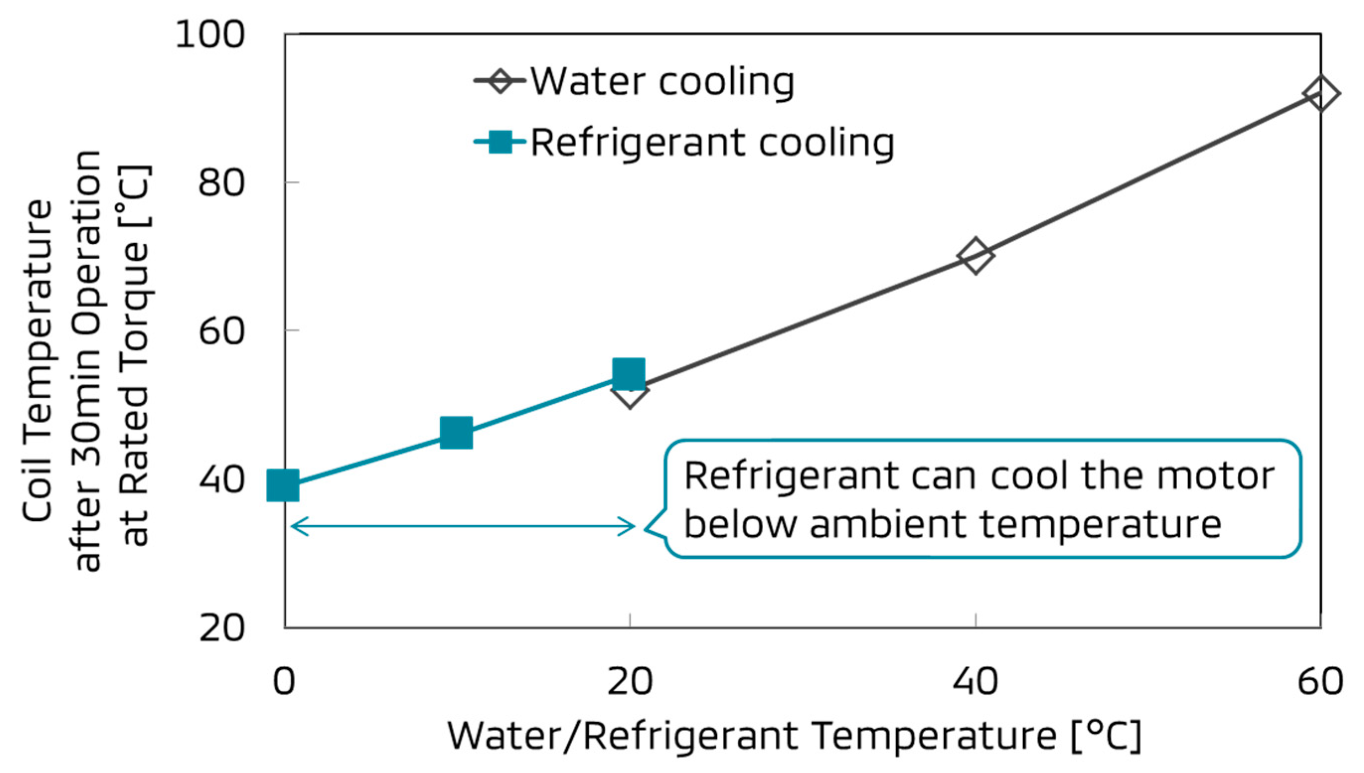
The coil temperature was proportional to the temperature of fluid through the water jacket as shown in
Figure 6, which shows the higher cooling performance of the refrigerant cooling. The compressor achieved this result by keeping the refrigerant temperature below the ambient temperature for its phase transition causing an endothermic reaction through the TXV.
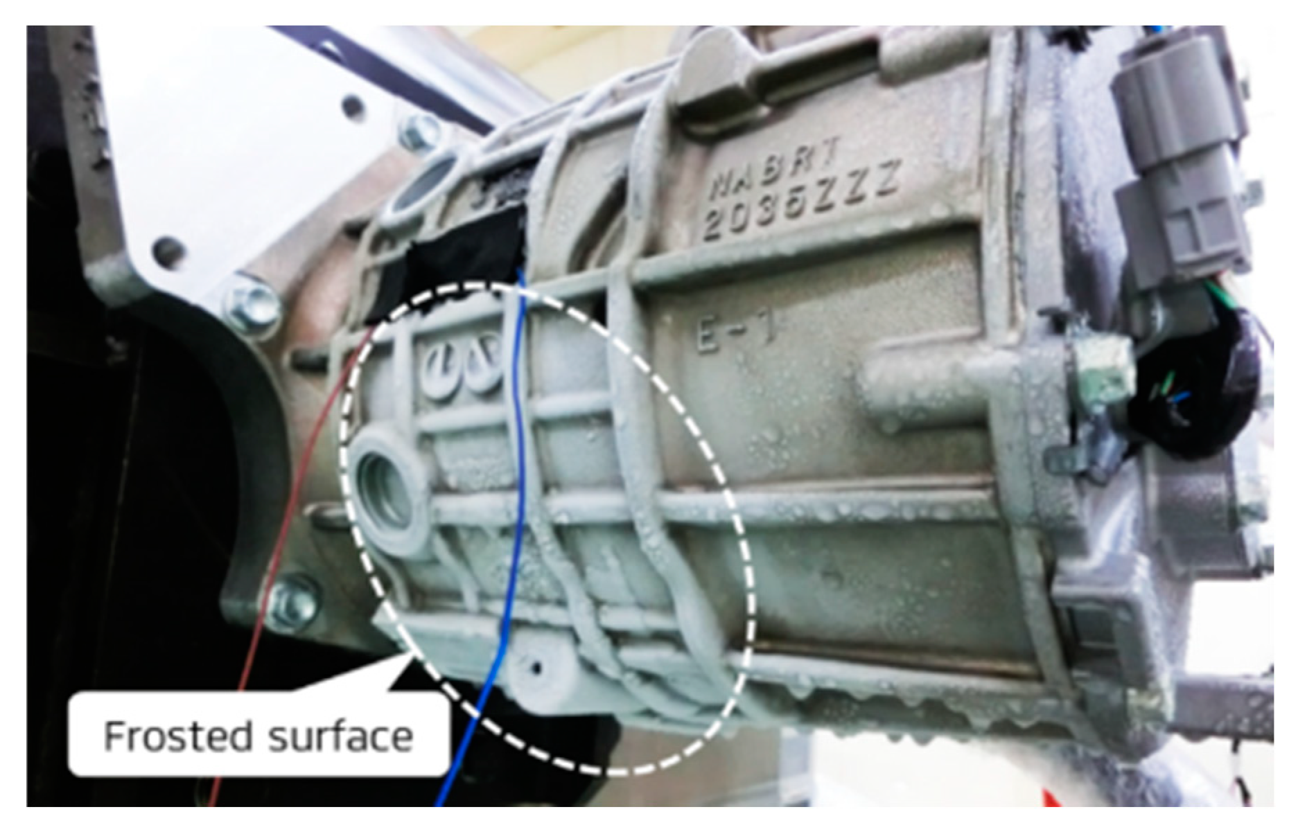
Figure 7 shows higher cooling performance of refrigerant cooling. The picture was taken after 30 min of motor operation at rated torque. The motor surface was frosted since the refrigerant temperature was set at 0 °C.
4.2.2. Experiment 2
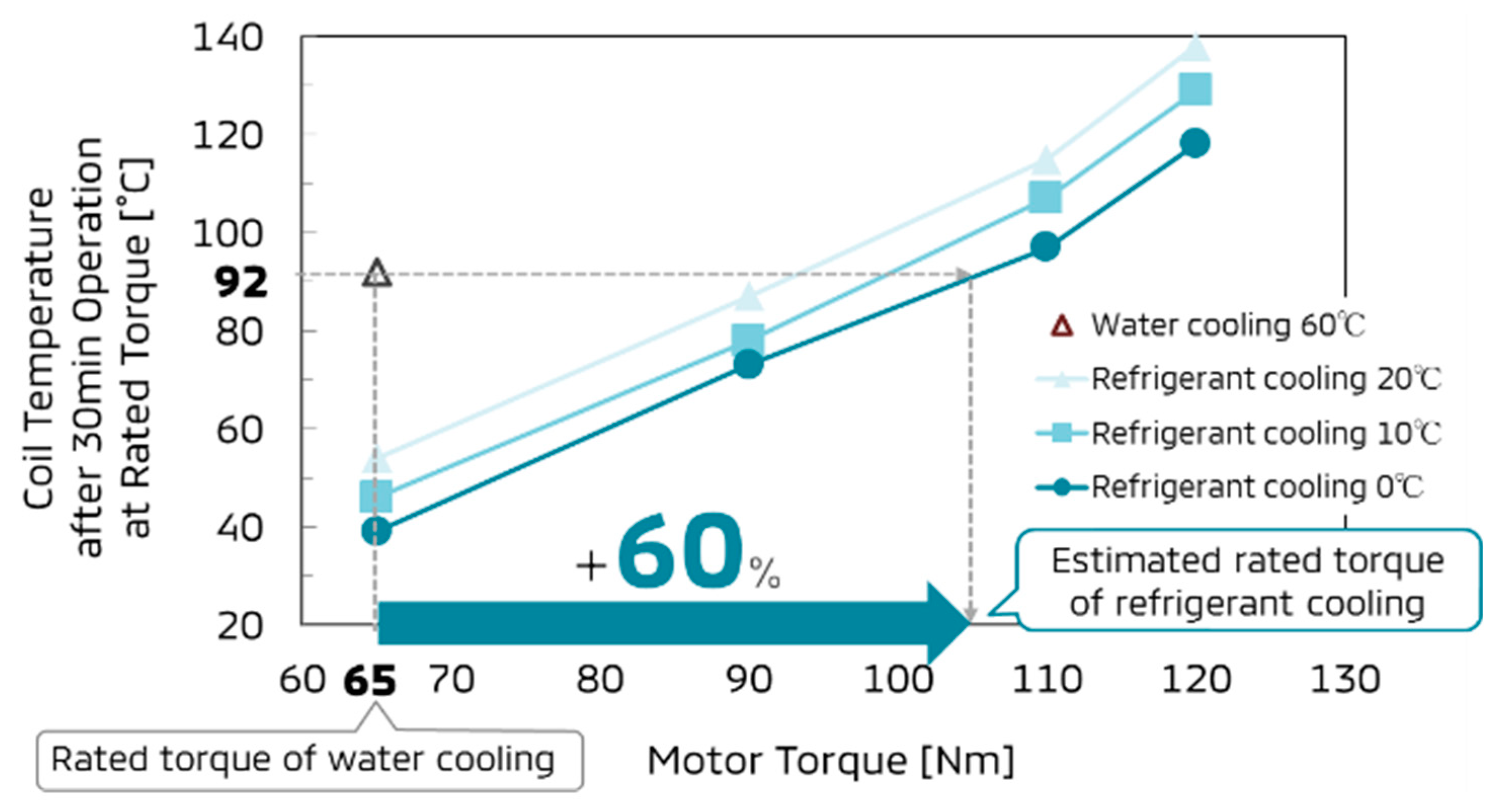
Figure 8 shows that the rated torque of the refrigerant cooling increased up to 60% more than that of the water cooling. The new rated torque was estimated from the highest coil temperature of the water cooling. After the operation of the water cooling motor with the water temperature of 60 °C operated for 30 min at the rated torque of 65 Nm, the coil temperature reached 92 °C. This result indicates that the rated torque of the refrigerant cooling is allowed to increase until the coil temperature becomes 92 °C. In that case, the motor torque was 105 Nm while the refrigerant cooling was 0 °C. That was a 60% increase of the rated torque of the refrigerant cooling as a result of replacing the cooling substance from water to refrigerant.
4.2.3. Experiment 3
Experiment 3 aims to clarify any impact on the maximum torque of the refrigerant cooling. Note that the inverter performance restricts the maximum torque. What was focused on here was whether refrigerant cooling affected the operation time at maximum torque. The results showed two aspects.
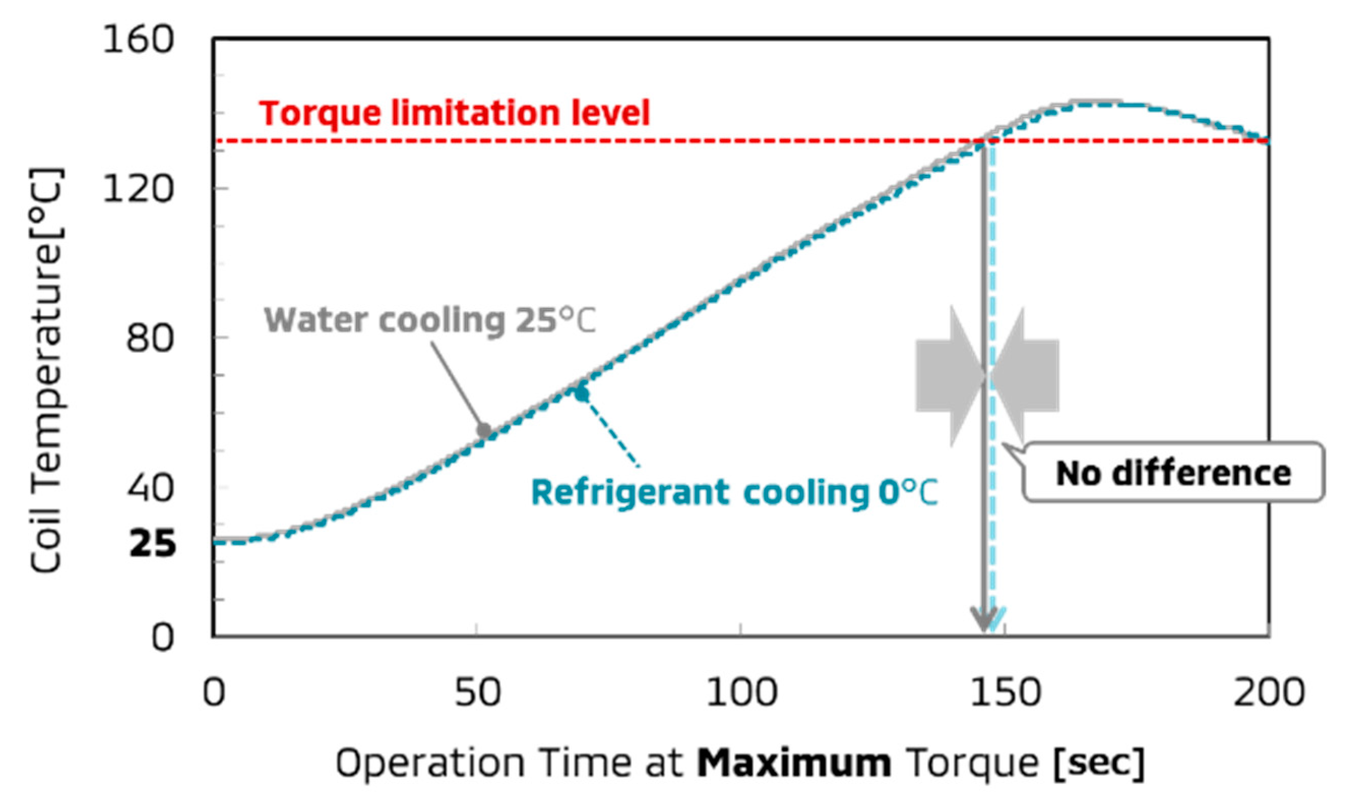
First, cooling methods did not affect any operation time if the initial coil temperature was same as shown in
Figure 9. The time range of 150 s was too short for refrigerant cooling to show its effect.
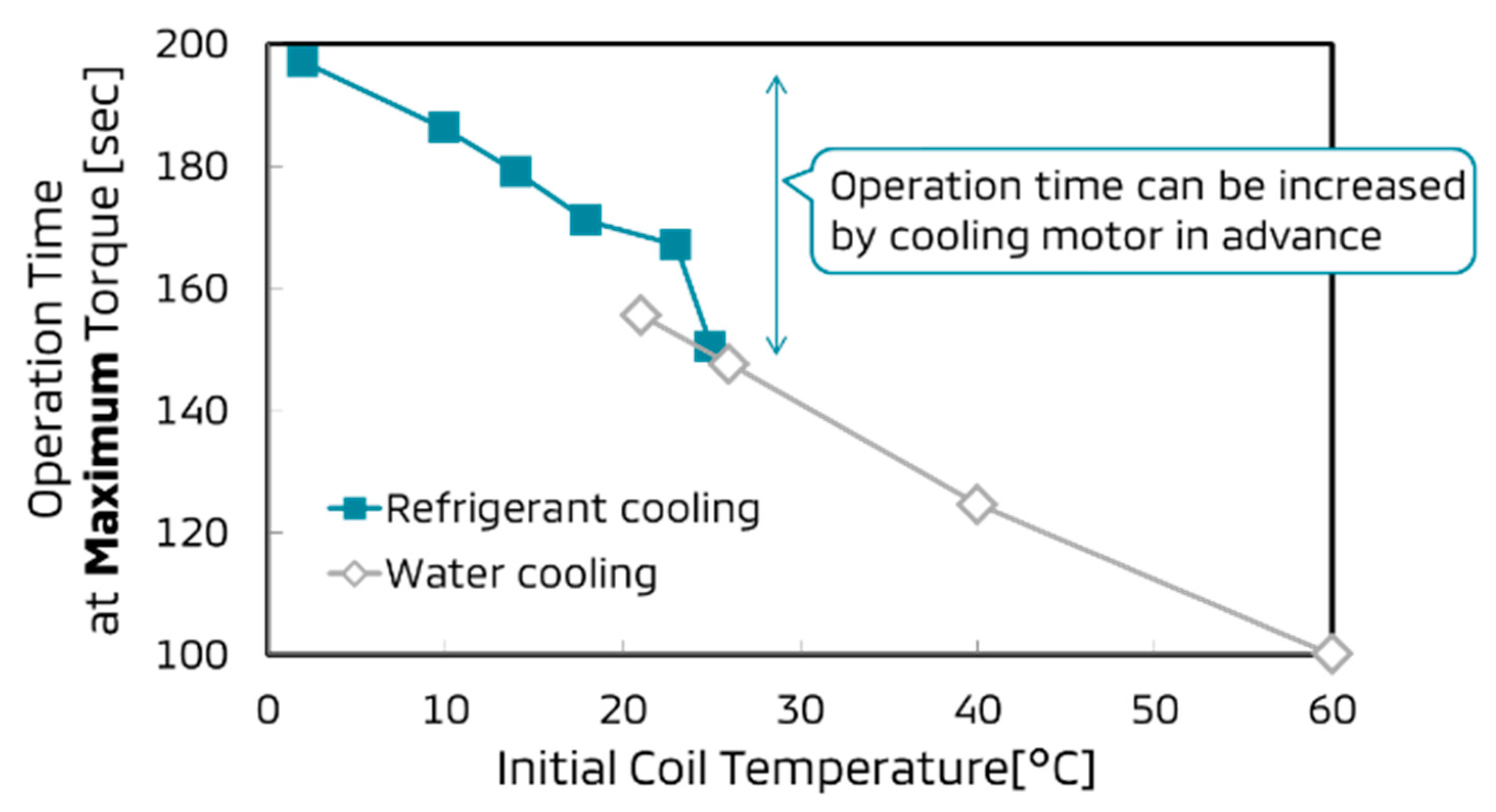
However, when the motor was cooled down to 0 °C in advance of motor operation, the operation time at the maximum torque of the refrigerant cooling was extended by 34% as
Figure 10 shows.
Figure 11 shows that the lower initial coil temperature led to the longer operation time. In other words, the refrigerant cooling had an advantage over the water cooling since the compressor decreased the initial coil temperature before the motor operation.
5. Conclusions
The superiority of the refrigerant cooling has been revealed comparing to the conventional water cooling, because:
The refrigerant cooling has the coil temperature lower than ambient temperature by the compressor control;
The rated torque was increased by 60% when the water cooling was replaced by the refrigerant cooling; and
Cooling the motor in advance of motor operation contributed to extend operation time at the maximum torque by 34%.
Author Contributions
Conceptualization, H.F.; formal analysis, A.I.; investigation, H.F.; writing—original draft preparation, H.F.; supervision, T.U.
Funding
This research received no external funding.
Acknowledgments
The authors would like to thank K. Sakai, K. Kusafuka, and K. Nasu for technical assistance with the experiments. We also thank S. Kino, E. Ishimaru and H. Hayakawa for great technical advice and Y. Nakajima and S. Kito for supporting paper construction. Finally, we are grateful to K. Handa for giving us the opportunity to continue this research.
Conflicts of Interest
The authors declare no conflict of interest.
References
- Ishimaru, E.; Yoshida, H.; Hayakawa, H. Changes in miniaturization and performance of the traction motor for EV/PHEV in Mitsubishi motors. In Proceedings of the 2014 IEE-Japan Industry Applications Society Conference, Tokyo, Japan, 26–28 August 2014. No.4-S9-4 (In Japanese). [Google Scholar]
- Fujimoto, H.; Takeuchi, T.; Hata, K.; Imura, T.; Sato, M.; Gunji, D. Development of Second Generation Wireless In-Wheel Motor with Dynamic Wireless Power Transfer. In Proceedings of the EVS31&EVTec 2018, Kobe, Japan, 30 September–3 October 2018. No. 20189136. [Google Scholar]
- Sano, S.; Yashiro, T.; Takizawa, K.; Mizutani, T. Development of New Motor for Compact-Class Hybrid Vehicles. World Electr. Veh. J. 2016, 8, 443. [Google Scholar] [CrossRef]
- Davin, T.; Pellé, J.; Harmand, S.; Yu, R. Experimental study of oil cooling systems for electric motors. Appl. Therm. Eng. 2015, 75, 1–13. [Google Scholar] [CrossRef]
- Nagamori, T.; Matsubara, J.; Sukaguchi, Y.; Suwazono, T.; Arigami, T.; Oyadomari, M.; Morikawa, A. Development of Motor System for Outlander PHEV. In Proceedings of the EVTeC and APE Japan 2014, Yokohama, Japan, 22–24 May 2014. No. 20144050. [Google Scholar]
- Kamei, H.; Nakano, Y.; Aoki, J.; Ashikaga, T. Development of a High Performance & High Power Density Inverter Integrated Motor Unit. In Proceedings of the EVS31&EVTec 2018, Kobe, Japan, 30 September–3 October 2018. No. 20189139. [Google Scholar]
- Aranzabal, I.; de Alegria, I.M.; Garate, J.I.; Andreu, J.; Delmonte, N. Two-phase liquid cooling for electric vehicle IGBT power module thermal management. In Proceedings of the 2017 11th IEEE International Conference on Compatibility, Power Electronics and Power Engineering (CPE-POWERENG), Cadiz, Spain, 4–6 April 2017. No. 16896418. [Google Scholar]
- Aranzabal, I.; Martinez de Alegria, I.; Delmonte, N.; Cova, P.; Kortabarria, I. Comparison of the Heat Transfer Capabilities of Conventional Single- and Two-Phase Cooling Systems for an Electric Vehicle IGBT Power Module. IEEE Trans. Power Electron. 2019, 34, 4185–4194. [Google Scholar] [CrossRef]
- GT-SUITE. Gamma Technologies. LLC. USA. Available online: www.gtisoft.com (accessed on 8 April 2019).
- Natarajan, S.; Sathish, K.S.; Amaral, R.; Rahman, S. 1D Modeling of AC Refrigerant Loop and Vehicle Cabin to Simulate Soak and Cool Down. SAE Tech. Paper 2013, 1, 1502. [Google Scholar] [CrossRef]
© 2019 by the authors. Licensee MDPI, Basel, Switzerland. This article is an open access article distributed under the terms and conditions of the Creative Commons Attribution (CC BY) license (http://creativecommons.org/licenses/by/4.0/).
