1. Introduction
The use of in-wheel motors (IWMs) in fully electric vehicles (EVs) brings about several benefits, such as enhanced actuator response and brake regeneration, which results in improved driving safety and motion control. Nowadays, a number of well-established engineering solutions for these chassis control systems (e.g., torque vectoring and wheel slip control) are already available for serial EVs [
1,
2,
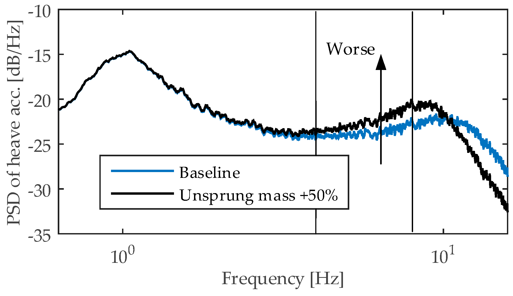
3]. However, IWMs may also have an adverse effect on ride comfort due to the increased unsprung mass, which causes higher vibration, particularly in the 4–8 Hz range, where humans are more sensitive to vertical accelerations [
4,
5,
6]. The effect of increased unsprung mass on ride comfort can be assessed through simulation analysis with the quarter-car model, where the road input is generated in accordance with ISO8606 [
7]. The corresponding power spectral density of the heave acceleration is reported in the
Figure 1 for the baseline case and the vehicle equipped with IWMs, respectively. In this analysis, the vehicle equipped with IWMs features a 50% increase of the unsprung mass for each wheel.
Several research instances investigated the effects of unsprung mass increase on the ride comfort. Anderson, Hurdwell, and Harty analyzed the impact that a 30 kg mass increase for each wheel has on the vehicle dynamics [
6,
8]. The results of this study demonstrated that such an increase of unsprung mass leads to the degradation of ride comfort in terms of pitch dynamics, impact feel on rough road, and agility. Another negative effect for some IWM design variants is that road excitations can lead to magnet gap deformation and, therefore, to magnetic force oscillations in the IWM [
9]. As a result, the tuning of suspension design for EV with IWMs is required with consideration of the effect of reduced frequency of the wheel hop. The solution to install a stiffer suspension cannot be sufficient because this leads to a higher EV body acceleration. Additional boundaries in this case are also set by the tyre stiffness. These arguments show that a tuning of the passive suspension has a limited applicability to improve the ride quality of the EV with IWMs that was also confirmed by some research works [
10]. These facts motivated further developments and studies for EV ride dynamics, which led to active ride control by means of IWM torque allocation.
This approach is based on the evidence that variations in the IWM torque allow for alteration of the wheel vertical force [
11], whose magnitude depends on the suspension layout [
12]. This effect can be exploited to reduce longitudinal vibrations [
13,
14,
15], vehicle pitch during braking/acceleration [
16,
17,
18], vehicle heave [
19], and suppress the roll motion [
20] when the lateral dynamics is excited. The mentioned effects were combined in Reference [
21] to suppress sprung mid-frequency vibrations on heave, pitch and roll motion by utilisation of IWMs on the rear wheels. Nevertheless, the improvement of EV ride comfort trough targeted IWM torque modulation has also functional limitations.
An analysis of previous solutions shows that a reasonable advancement can be brought to the integration of the AS with the IWM-based ride dynamics control. This article focuses on the driving comfort enhancement by means of blended operation of IWMs and ASs. At the present stage of research, IWM control is utilised only for pitch motion control. Without loss of generality, a different force allocation on the two sides of the vehicle can be used to generate an anti-roll moment and, thus, suppress the roll motion. The term “ride blending”, coined in a previous authors’ work [
22] and herein retained, is proposed by analogy with the brake blending, widely investigated in the research field related to EV. An experimentally validated model of a full electric sport utility vehicle (SUV), equipped with four IWMs, is used to investigate body’s heave, roll, and pitch, and wheels’ vertical motion. The vehicle model is based on the IPG CarMaker
® simulation platform, whilst the vehicle subsystems are realised in MATLAB/Simulink environment. To this effect, data collected at Tenneco Automotive (Belgium) are used to validate a second order system dynamics, which reproduces the real transient response of the AS system and consider physical system constraints.
Hereunto, the effectiveness of the proposed controller is demonstrated with respect to the following test scenarios: straight line braking, sine sweep, and brake-in-turn (ISO 7975). The vehicle used for test comparison is the same model SUV equipped with conventional internal combustion engine (ICE) and passive suspensions.
This work represents a follow-up research to the preliminary studies on ride blending presented at EVS31 conference in Kobe (Japan) with the paper titled “Ride Blending Control for Electric Vehicles” [
22]. The previous work only provides a general introduction to the ride blending controller and vehicle modelling. In the present article, the model has been improved to consider complex manoeuvres and an assessment criteria based on the key performance indexes is put forth. In this study, a decentralised control architecture has been used due to its simplicity of implementation. However, the authors envisage that a centralized controller would be more suitable for the ride blending in the multi-actuated SUV equipped with four ASs and four IWMs. In the future, a sophisticated centralized controller will be implemented and benchmarked against the decentralized architecture.
The authors acknowledge that the information herein reported represents new advancements in the field of ride blending control and have not been dealt with previously. The paper is organized as follows.
Section 2 puts forth the vehicle model and its subsystems. In
Section 3, the decentralized architecture and control functions thereof are presented. Simulation results are reported in
Section 4, which demonstrates the advantaged of the ride blending concept and the limitations of the decentralized control architecture. The performance of the AS with the IWM-based ride dynamics control is compared with the conventional passive suspension system. The enhancement in ride performance is reflected by improvement in key performance indexes (KPI) associated with driving comfort and active safety [
6].
3. Ride Blending Control
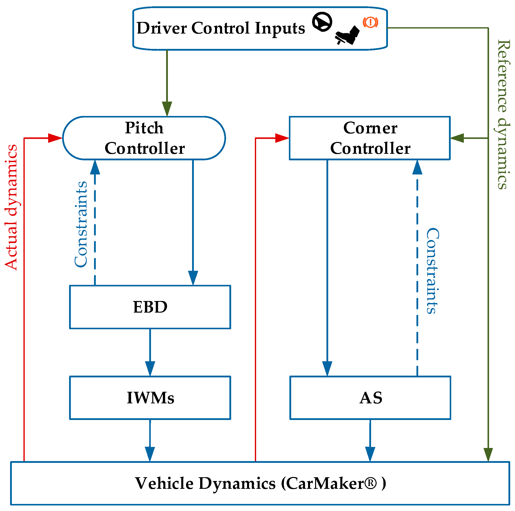
The proposed ride blending architecture is depicted in
Figure 6. This latter is based on the principle of decentralized control, which at this stage of research represents a good compromise between ease of implementation and control performance.
The “Pitch Controller” computes the reference states of the vehicle body dynamics for given manoeuvre conditions based on the “Driver Control Inputs”, as the positions of the acceleration and brake pedals. The mentioned reference states, which are sent to the electronic brake distribution (EBD), are at this stage of the research related to the pitch motion, as will be explained in the next section. The Corner Controller depends on the applied ride control targets, which are related to one or more tasks, as road holding, handling, pitch control, heave control, etc. The reference states are compared with the actual states of the vehicle body dynamics provided by the vehicle on-board sensors and state estimators. EBD and the Corner Controller set up the control current for IWMs and actuators of the ASs. They produce required wheel torques and vertical forces correspondingly. The system acts so that the control effort required from the Corner Controller is minimized once the EBD for minimum pitch intervenes. However, the limitations of this control algorithm will be discussed later on. The “Pitch Controller” and “Corner Controller” are based on the Proportional Integral (PI) controller, whose gains have been identified by analysing the frequency response for the closed-loop system of the driver vertical acceleration and angular rotations with varying vertical load and road input.
3.1. Electronic Brake Distribution (EBD) for Minimum Pitch
Brake proportioning is widely addressed in vehicle longitudinal dynamics to determine the brake force distribution between front and rear wheels without causing rear wheels to lock. While braking/accelerating or negotiating a turn, the vehicle is subject to a mass transfer that leads to a variation in the vertical load acting on a wheel. This leads to vehicle pitch and roll and, as a result, the vehicle driving comfort decreases. Vehicles equipped with IWMs can use the suspension reaction force generated by motor drive as a form of AS control [
12]. At the present stage of research, the differential EBD is utilized only for pitch motion control.
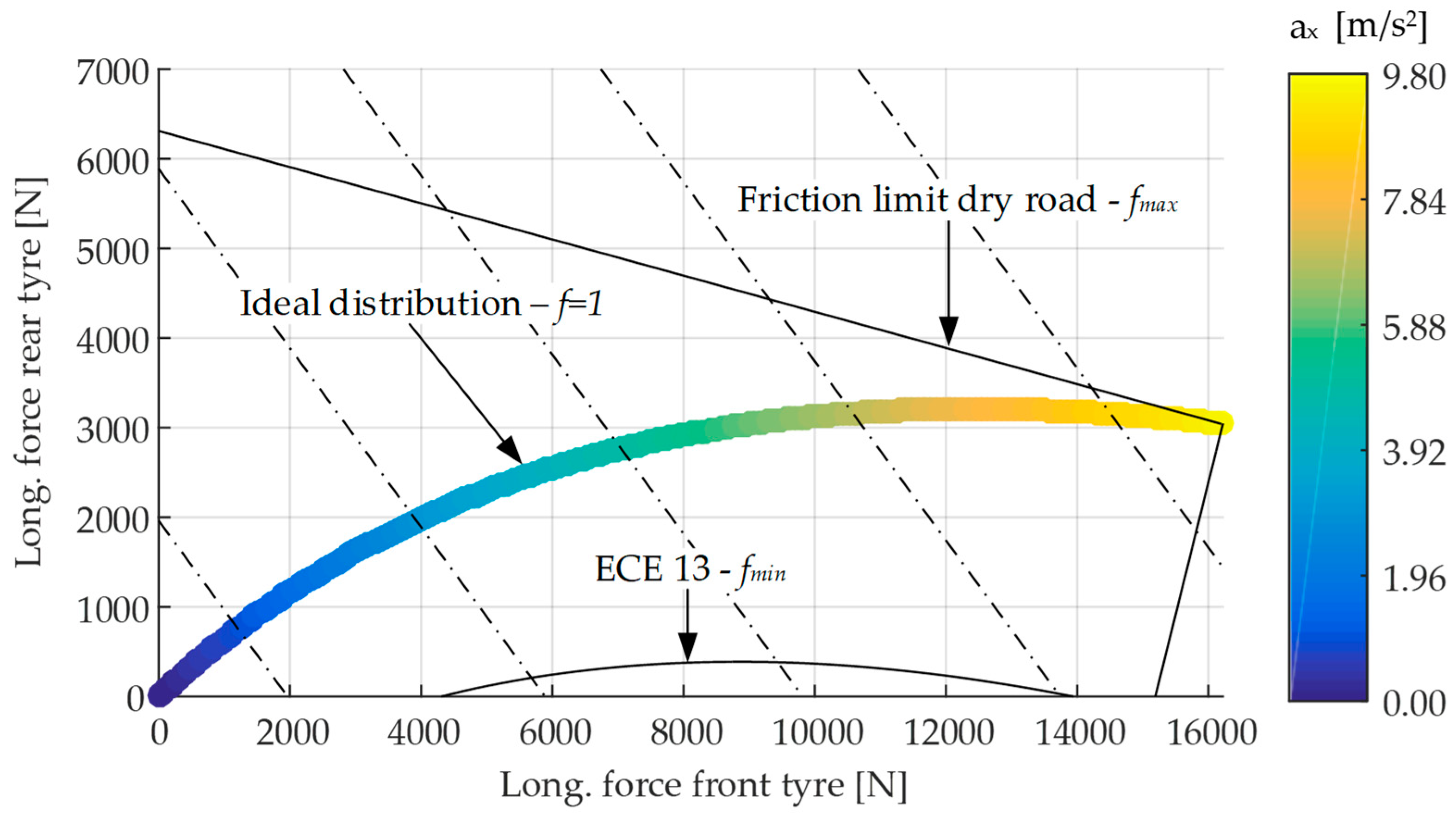
By controlling the magnitude of the motor torque provided to each wheel, the anti-dive/lift force can be used for pitch motion suppression. In fact, load transfer can occur not only during vehicle acceleration/deceleration but also because of the anti-dive/lift forces brought about by the IWM architecture. Relevant to this study is the definition of ideal force distribution, based on which front and rear wheels exhibit the same tyre–road friction utilization [
24]. The ideal force distribution against the braking acceleration demand is depicted in
Figure 7. A control parameter
is defined so that:
where,
and
are the longitudinal forces exerted by the front and rear wheels, respectively. The boundaries of the control parameter are reported in
Figure 7, where the upper limit account for tyre-road friction utilisation on dry road and the lower limit complies the Regulation 13 ECE [
25]. These constraints set the limits to avoid the rear wheels lock during braking. A control parameter equal to one means that the torque distribution is realized in accordance with the ideal curve. The “Pitch Controller” selects the control target to suppress the pitch motion by simultaneously ensuring the demanded acceleration/braking performance. Thereafter, the signal is processed by the EBD, which in turn actuates the IWMs.
The same strategy is applied in the case of acceleration but it is here omitted for the sake of space. This strategy ensures that the pitch angle is reduced whilst the driver request is preserved.
3.2. Corner Controller
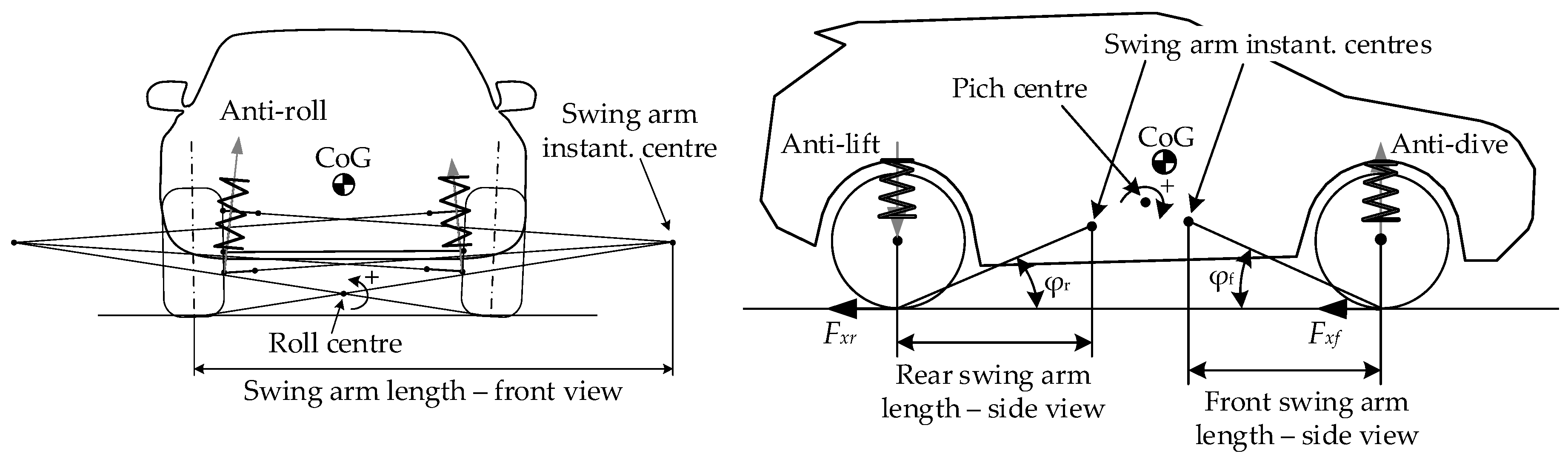
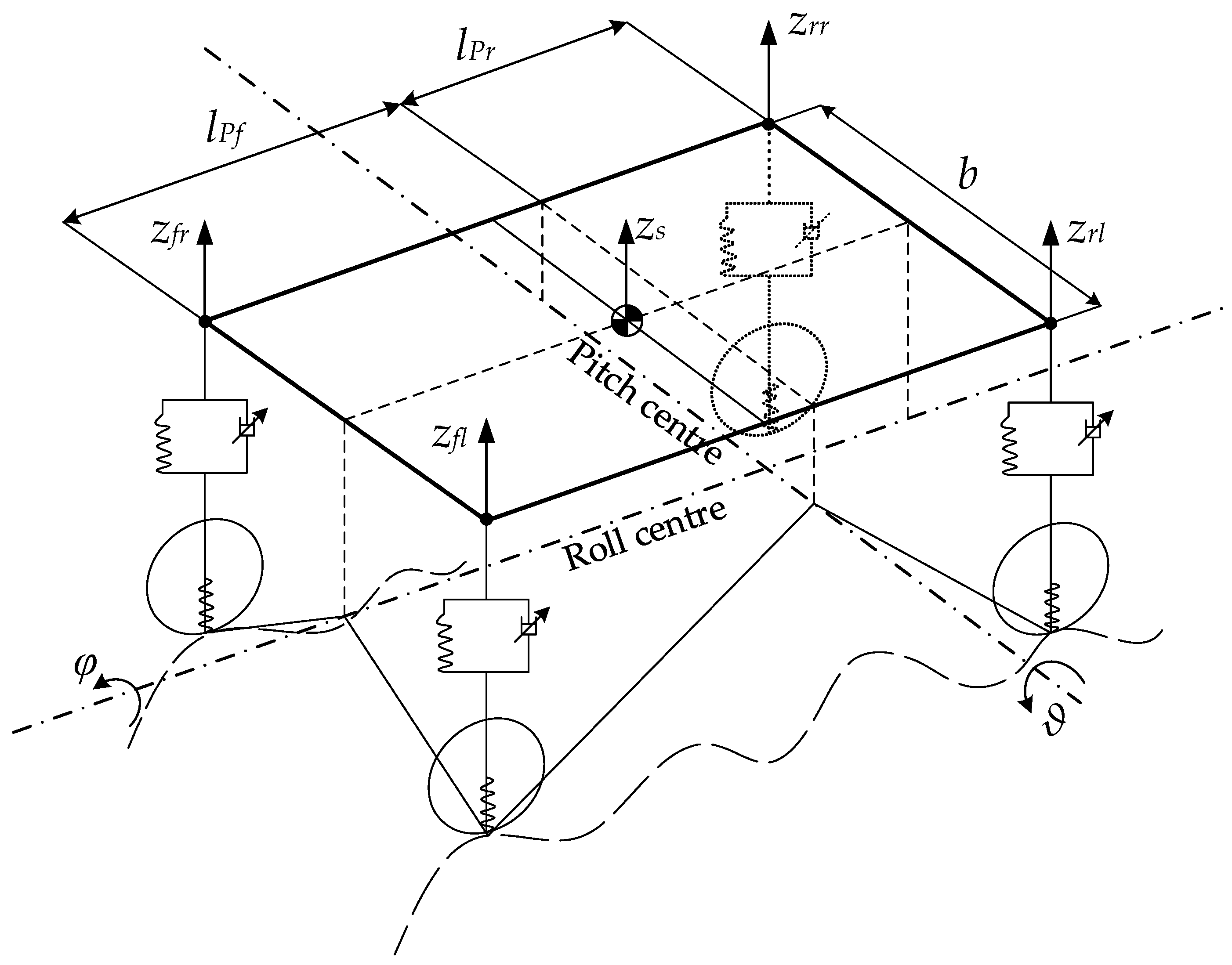
The corner controller employs the information of body pitch angle
, roll angle
and heave displacement
to estimate the position of the suspension top-mount point
. Thereafter, the controller acts to minimize the acceleration of the top-mount positions, which results in an improved driving comfort. To this effect, the estimator requires the values of instantaneous pitch and roll centres positions, which are computed in accordance with the kinematics of the vehicle model depicted in
Figure 8.
For small displacements and rotations, the following set of equations holds:
where,
is the wheel track and
and
represent the distance of the pitch centre from the front and rear wheel centre, respectively. Hence, the control input acts to suppress the acceleration of the top-mount points. Given the linearity of the problem (3), this control provides a simultaneous abatement of heave, pitch, and roll motion.
4. Simulations
The proposed ride blending architecture was implemented in the proprietary vehicle dynamics simulation software IPG CarMaker
®, which includes aerodynamic forces, non-linear suspension model, non-linear IWMs model, a complex model of the electrohydraulic brake system, and steering system. The experimentally validated SUV-class vehicle and tyre Magic formula [
23] were used during the simulations. The characteristics of the vehicle are reported in the
Table 1.
The full electric SUV equipped with enabled ride blending is compared against its ICE counterpart, characterized by a lower unsprung mass. Three simulations are performed to assess the effectiveness of the proposed controller, namely the straight line braking, the sine sweep test, and the brake-in-turn (ISO 7975). The effectiveness of the proposed controller is enumerated by KPI associated with driving comfort and active safety. The driving comfort indexes are herein related to the RMS of the heave, pitch, and roll accelerations, respectively. The active safety is reflected by the RMS of the wheel vertical load variations, which have a detrimental effect on the tyre grip. The KPI are defined so that higher values correspond to better or safer performance. For the sake of clarity, the KPI are normalized with respect to the technology that achieve the highest score in terms of pitch, roll, heave suppression, and road holding.
4.1. Straight Line Braking
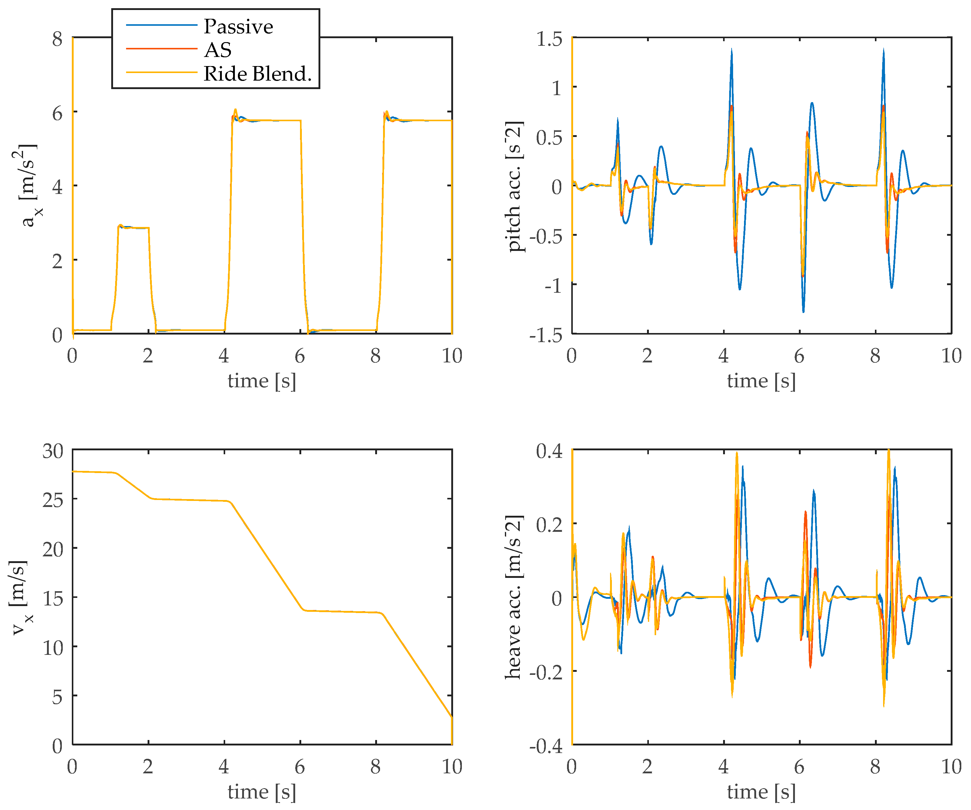
In the first scenario, the vehicle starts from an initial speed of 100 km/h and performs three consecutive braking manoeuvres until a stand still. The results of this simulation are reported in the
Figure 9 and refer to three configurations, namely: the conventional SUV with passive suspension system (referred to as “Passive”), the full electric SUV equipped with ASs (also referred to as “AS” in the figure) and the upgraded configuration with ride blending control (referred to as “Ride Blending”). It is worth remarking that the controller preserves the same braking performance, achieving a pitch reduction without affecting the braking distance.
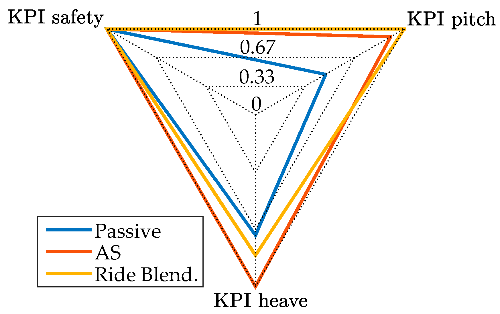
It is worth pointing out that superior performance in terms of pitch motion suppression can be achieved through blended action of IWM torque control and ASs (referred to as Ride Blend. in the figures). Indeed, the peak acceleration value is dramatically abated thanks to the braking torque distribution for minimum pitch. The results are confirmed by the KPI reported in the
Figure 10. The KPI related to the roll motion is omitted because the associated dynamics is not excited during this test.
The results suggest that the ride blending control leads to improved pitch comfort with no deterioration of road holding. However, the EBD for minimum pitch has a detrimental effect on the vehicle heave as per
Figure 10.
4.2. Sweep Test
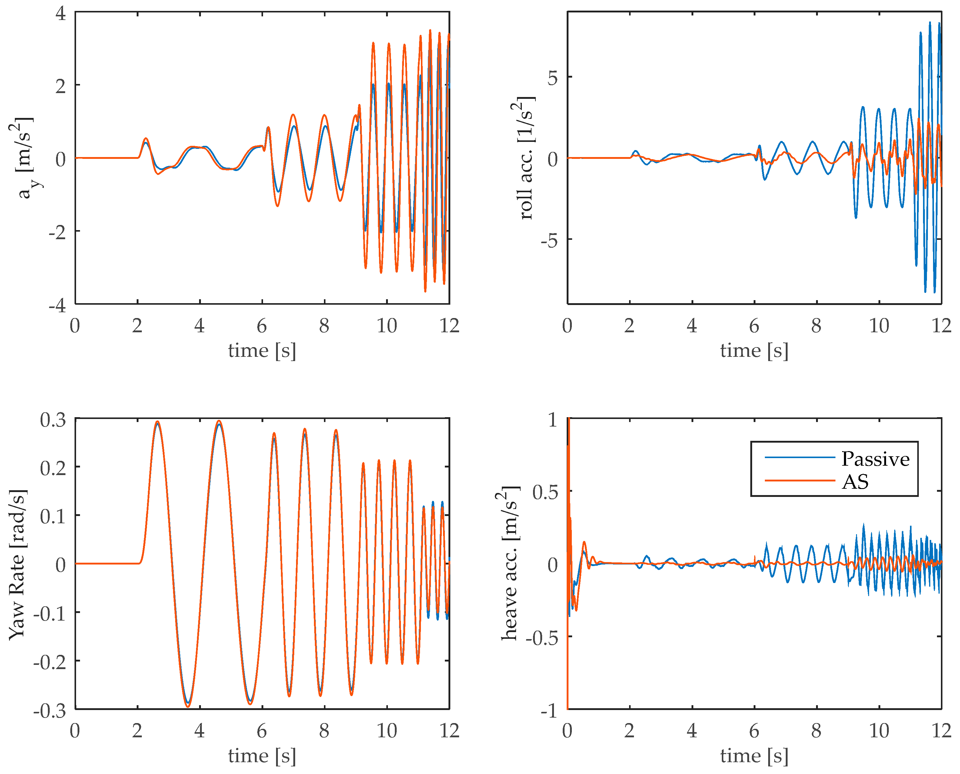
The second test involves a constant driving speed of 50km/h and a sinusoidal steering input. The swept sine test is performed to quantify the vehicle handling response to a steer input that covers a wide range of frequencies, namely from 1 Hz to 5 Hz.
Figure 11 shows the performance of roll and heave for the sine sweep test. For this test, the ride blending corresponds to the AS control, as the EBD for minimum pitch is disabled due to limited pitch motion. The AS control improves the roll motion for the whole frequency spectrum guaranteeing the driving performance.
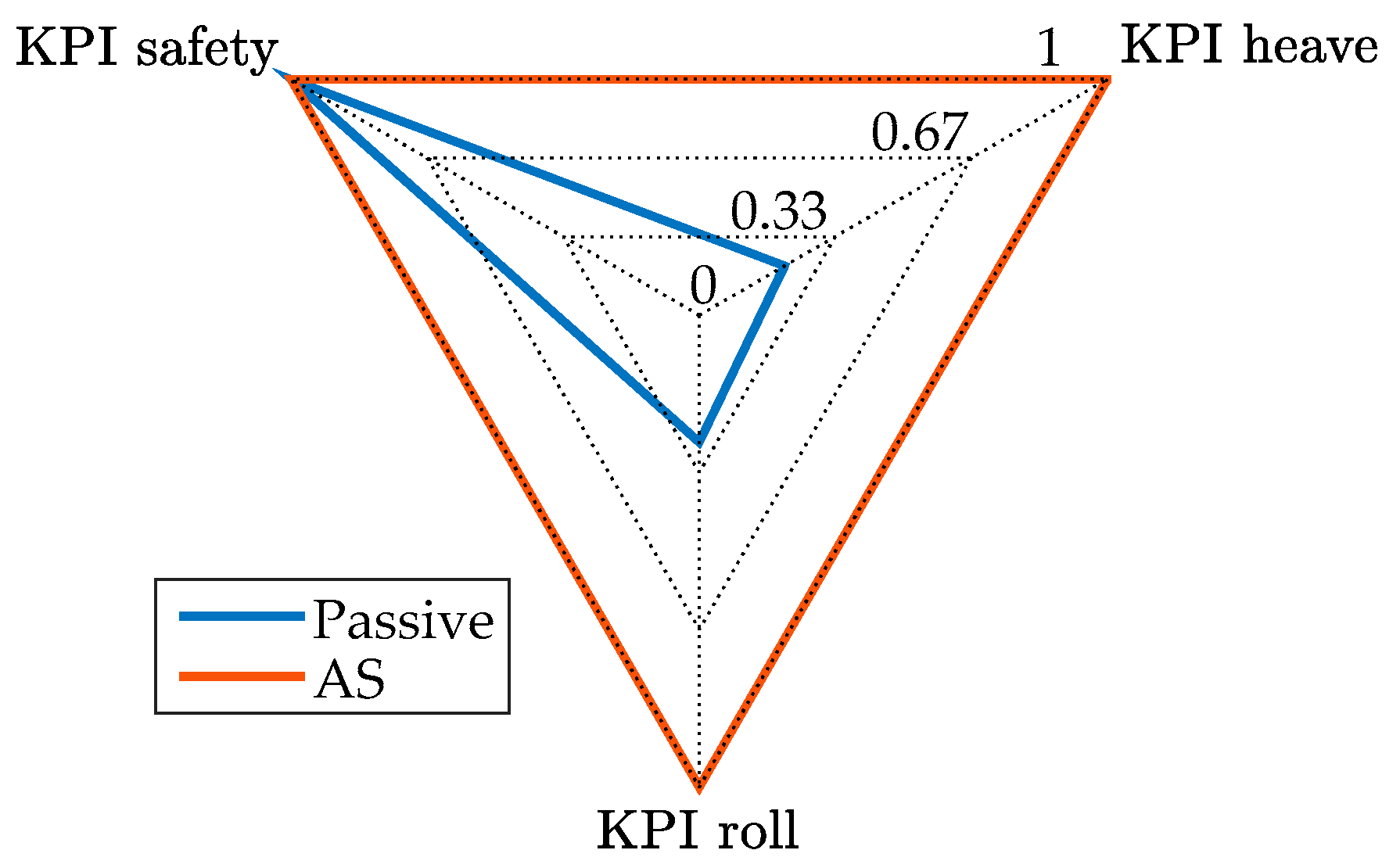
The enhanced performance is confirmed by the increased KPI in
Figure 12. Such analysis supports the previous statement and confirms that the AS control increases the driving comfort. The KPI related to the pitch motion is omitted because the associated dynamics are not excited in this test.
4.3. Brake-In-Turn (ISO 7975)
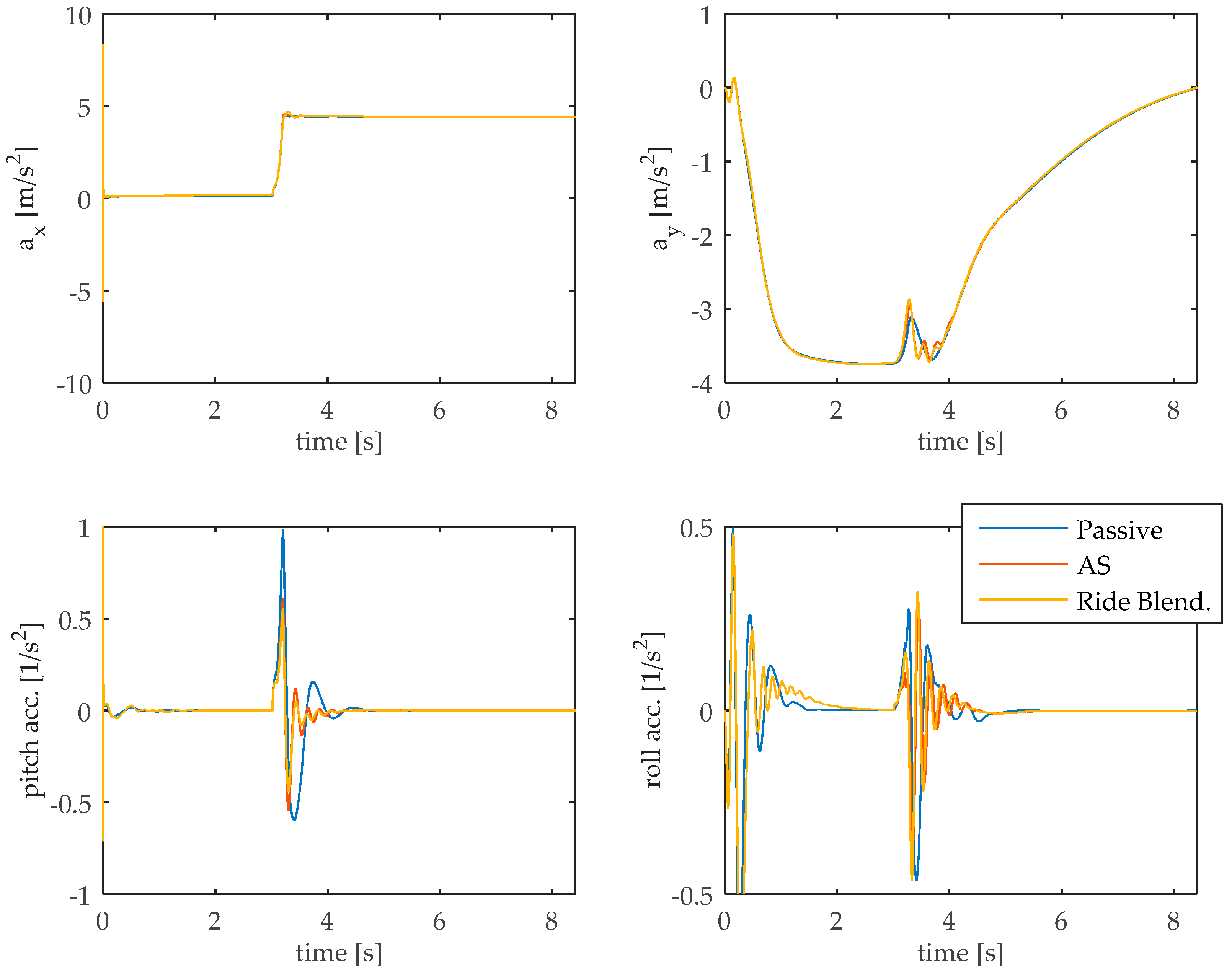
The last manoeuvres pertain to closed-loop brake-in-turn simulation on a dry road to investigate the effectiveness of the proposed ride blending controller when all the dynamics are excited. The performed simulation is based on ISO 7975 standard. The simulation results are reported in
Figure 13. For a matter of clarity, the diagrams are limited to the time span where the brake-in-turn occurs.
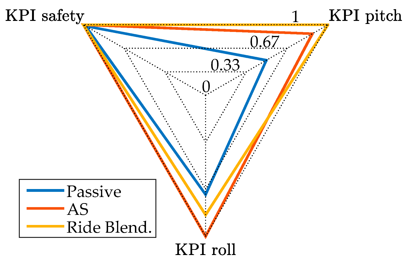
The upper-left graph proves that the proposed controller does not affect the driving performance. The suppression of roll, pitch, and heave motion proves the superior performance of the proposed AS controller. The KPIs for the brake-in-turn are reported in the
Figure 14.
The strong pitch and roll dynamics caused by this test emphasize the limitations of the decentralized controller. Although the decentralized Ride Blending control offers benefits in terms of pitch control, it has a detrimental effect on the roll motion. Indeed, the implemented decentralized controller is not able to account for the coupled dynamics of pitch and roll when it comes to the combined brake-in-turn manoeuvre. The authors envisage that a more sophisticated centralized controller will be able to deal with this issue. Nevertheless, as for the previous tests, the ride blending has no detrimental effect of the road holding performance.

 ,
, 


