85 kHz Band 44 kW Wireless Rapid Charging System for Field Test and Public Road Operation of Electric Bus

 ,
,
Abstract
:1. Introduction
2. Materials and Methods
2.1. Principal Specification of 85 kHz Band 44 kW Wireless Charging System for Electrice Buses
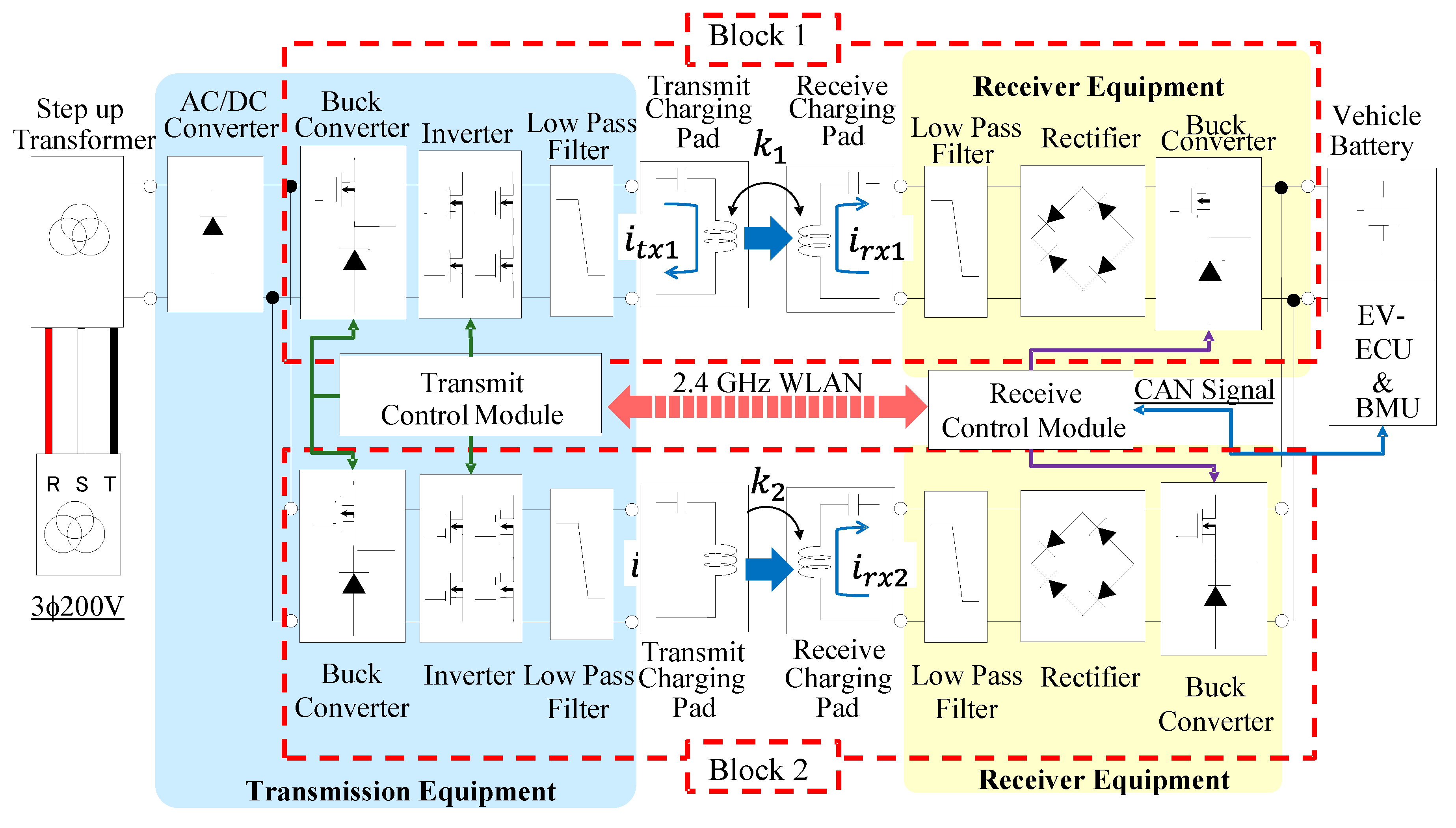
2.2. Block diagram of 85 kHz band 44 kW Wireless Charging System
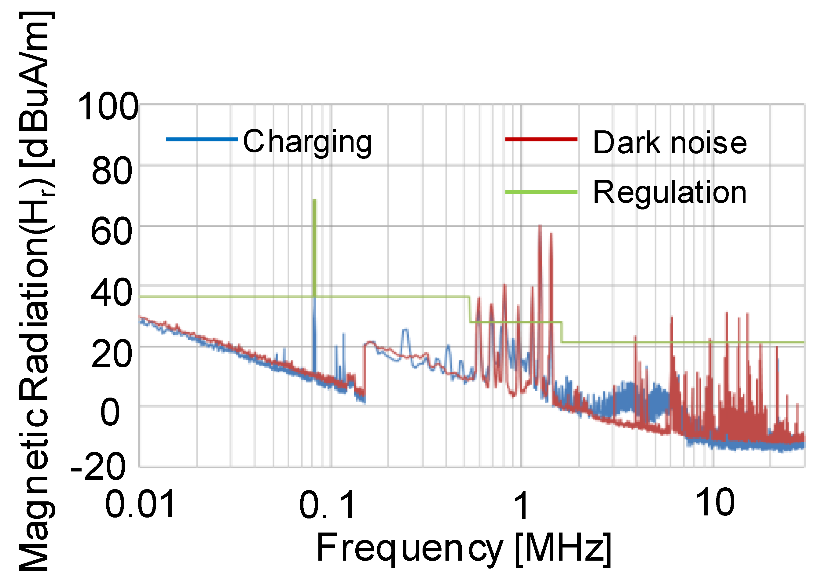
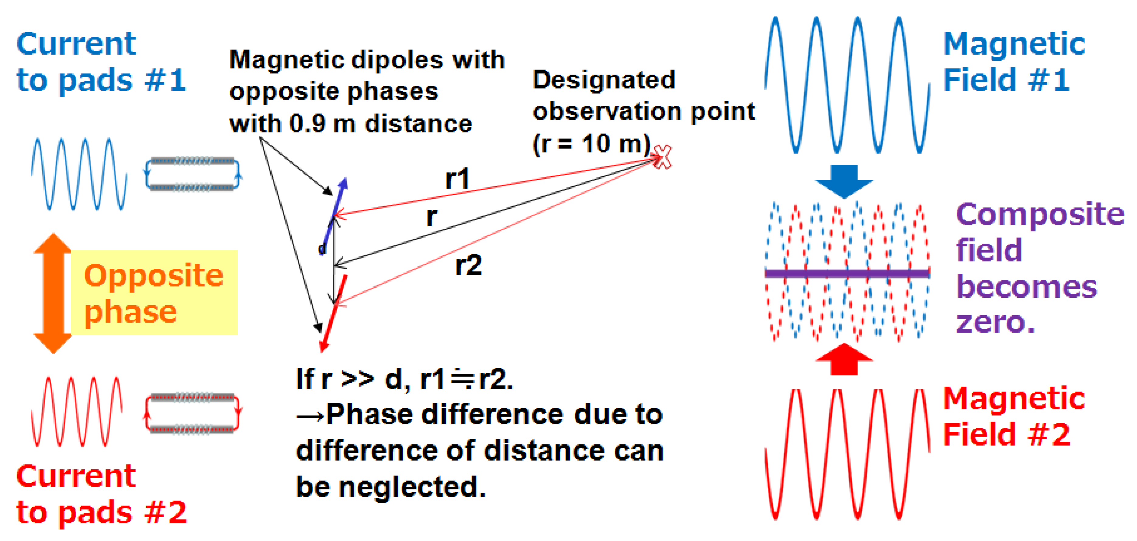
2.3. Dual-Block Parallel Transmission for Suppression of Magnetic Radiation
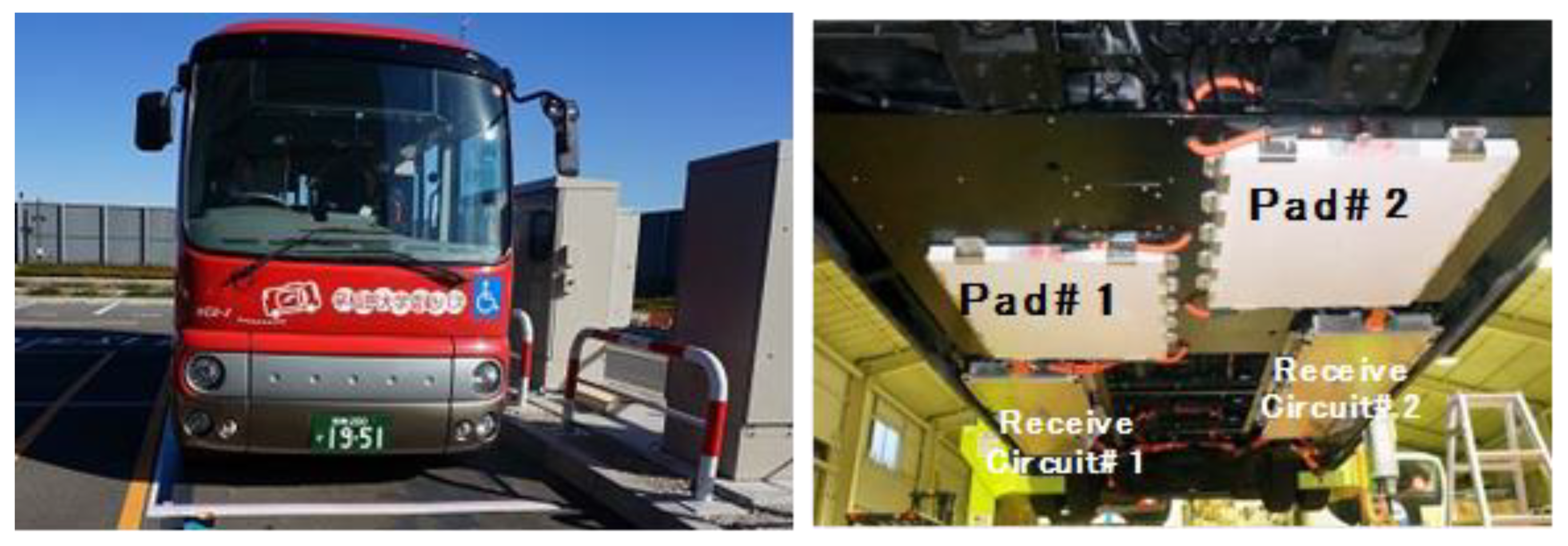
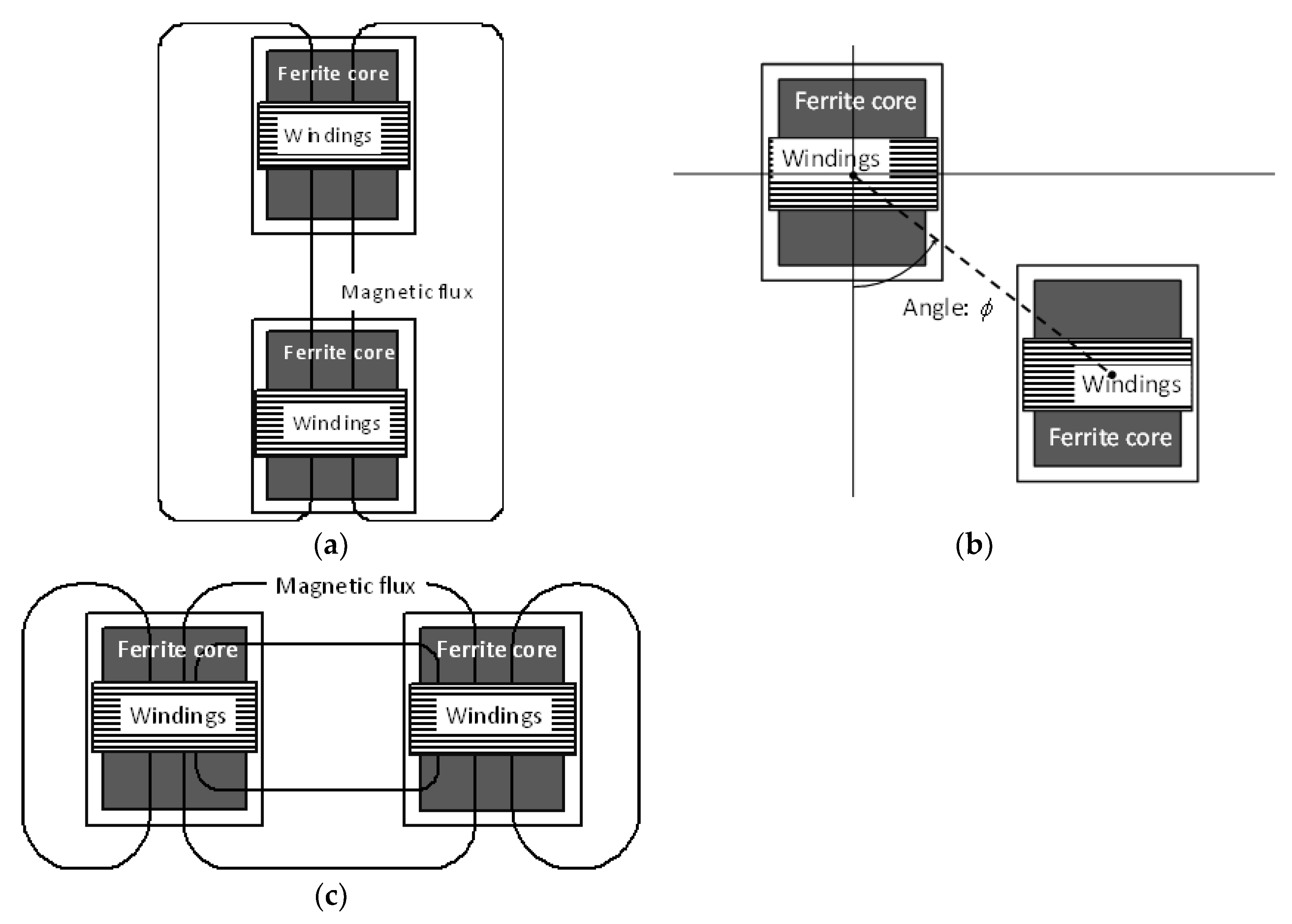
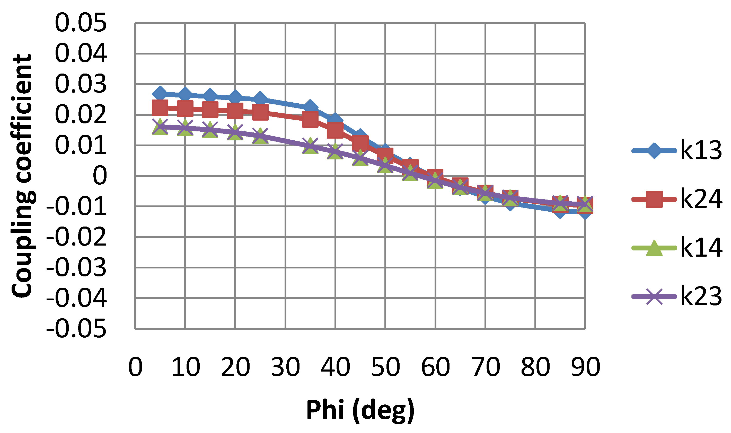
2.4. Diagonal Placement of Two Sets of Solenoid Pads to Reduce Interference Couplings
3. Results
3.1. In-Situ Measurement of Magnetic Radiation from Wireless Charging System Installed in Parking Lots
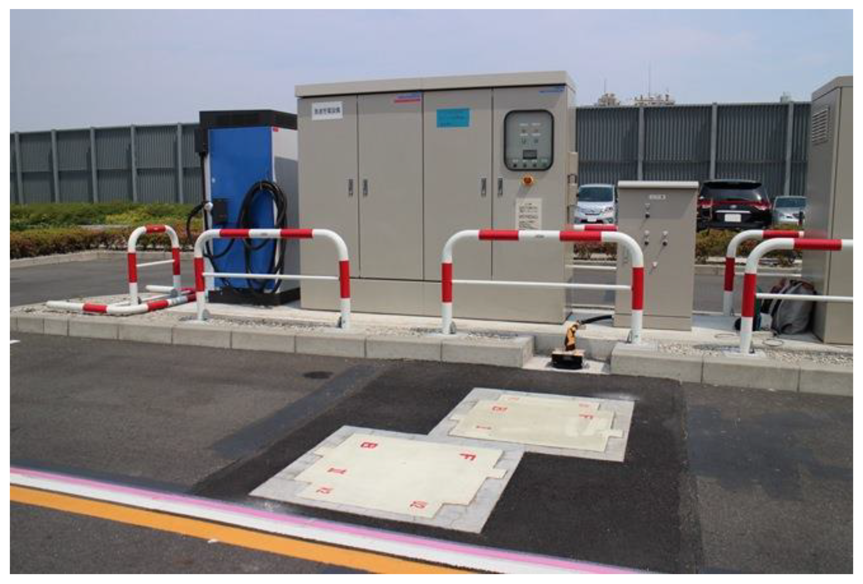
3.1.1. Transmission Equipment in Parking Lot
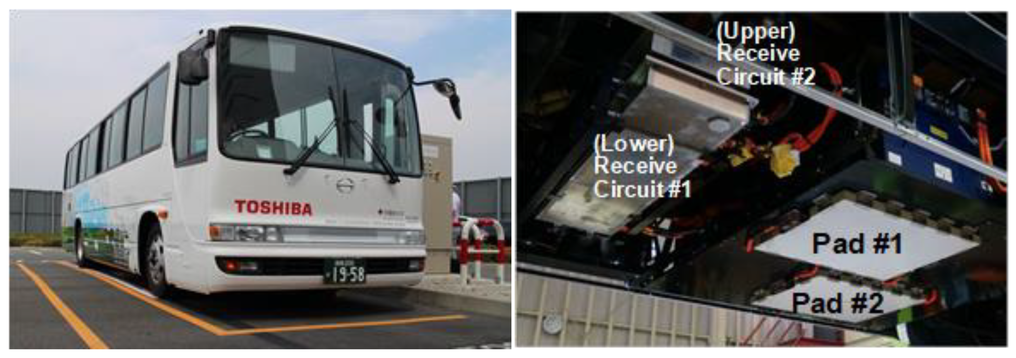
3.1.2. Receiving Equipment Installed in Small Buses and Medium-Sized Buses
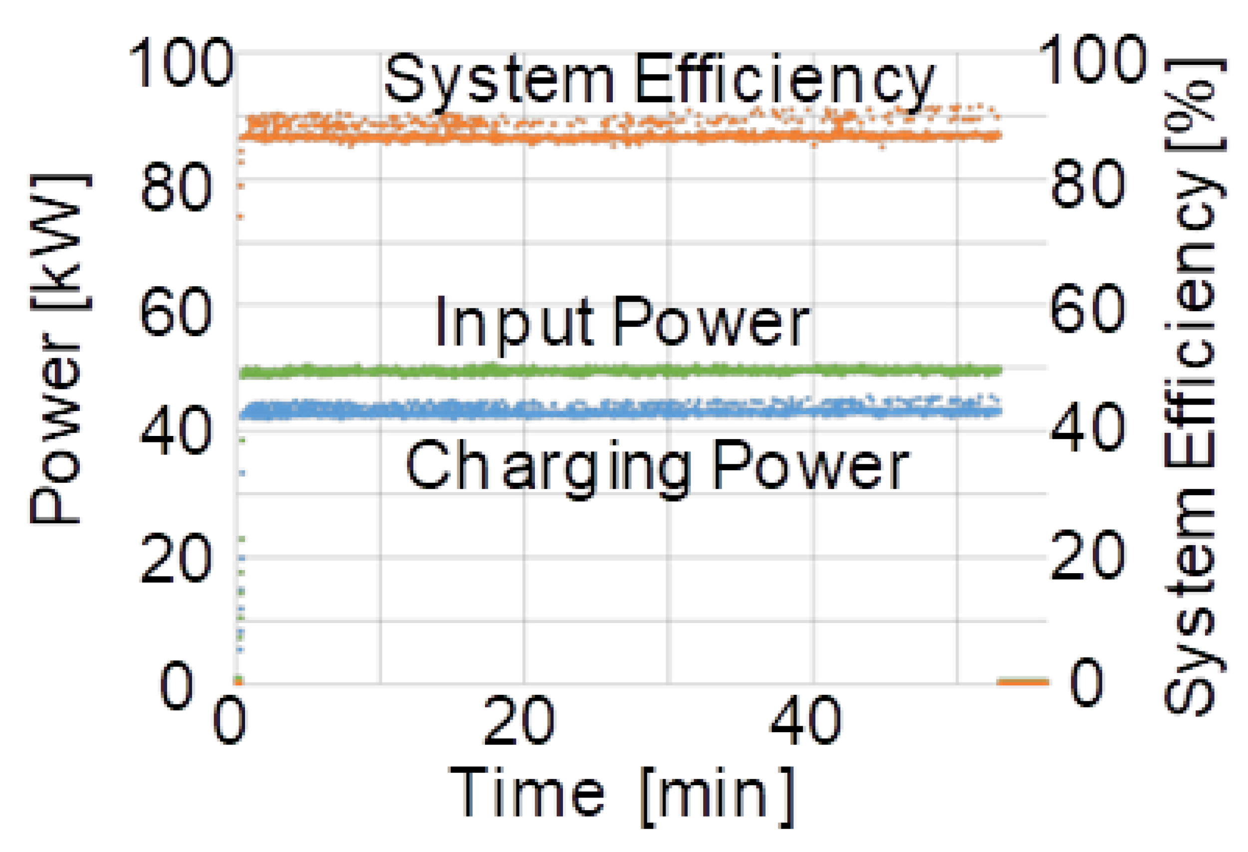
3.1.3. In-Situ Measurement of DC Charging Power, Power Efficiency and Magnetic Radiation
3.2. Field Test of Emulated Bus Operation on Public Roads
4. Discussion
Author Contributions
Funding
Acknowledgments
Conflicts of Interest
References
- Pontefract, T.; Kobayashi, K.; Miyasaka, Y.; Tanaka, K.; Kamiya, Y.; Daisho, Y.; Takahashi, S. Development and performance evaluation of an electric mini bus equipped with an inductive charging system. In Proceedings of the FISITA 2012 World Automotive Congress, Beijing, China, 27–30 November 2012; Volume VII, F2012-B07-002. pp. 887–898. [Google Scholar]
- Toshiba’s First Commercial Electric Bus to Run in Kawasaki. Available online: https://www.toshiba.co.jp/about/press/2015_03/pr3102.htm (accessed on 15 April 2019).
- Super Quick Charge-Electric Buses Enter Service in Malaysia. Available online: https://www.toshiba.co.jp/cs/en/topics/back-number/20170828.htm (accessed on 15 April 2019).
- Covic, G.A.; Boys, J.T. Inductive Power Transfer. Proc. IEEE 2013, 101, 1276–1289. [Google Scholar] [CrossRef]
- Kurs, A.; Karalis, A.; Moffatt, R.; Joannopoulos, J.D.; Fisher, P.; Soljacic, M. Wireless Power Transfer via Strongly Coupled Magnetic Resonance. Science 2007, 317, 83–86. [Google Scholar] [CrossRef] [PubMed]
- Shoki, H. Issues and Initiatives for Practical Deployment of Wireless Power Transfer Technologies in Japan. Proc. IEEE 2013, 101, 1312–1320. [Google Scholar] [CrossRef]
- Joung, G.B.; Cho, B.H. An energy transmission system for an artificial heart using leakage inductance compensation of transcutaneous transformer. IEEE Trans. Power Electron. 1998, 13, 1013–1022. [Google Scholar]
- Wang, C.-S.; Covic, G.A.; Stielau, O.H. Power Transfer Capability and Bifurcation Phenomena of Loosely Coupled Inductive Power Transfer Systems. IEEE Trans. Ind. Electron. 2004, 51, 148–156. [Google Scholar] [CrossRef]
- SAE International. Wireless Power Transfer for Light-Duty Plug-in/Electric Vehicles and Alignment Methodology (J2954_201904); SAE International: Warrendale, PA, USA, 23 April 2019. [Google Scholar]
- Obayashi, S.; Shijo, T.; Suzuki, M.; Moritsuka, F.; Ogawa, K.; Ogura, K.; Kanekiyo, Y.; Ishida, M.; Takanaka, T.; Tada, N.; et al. 85 kHz band 44 kW wireless rapid charging system for field test and public road operation of electric bus. In Proceedings of the EVS31 and EVTeC 2018, Kobe, Japan, 30 September–3 October 2018. [Google Scholar]
- Obayashi, S. 85 kHz band 44 kW wireless rapid charging system for electric bus. In Proceedings of the 23rd ITS World Congress, Melbourne, Australia, 10–14 October 2016. [Google Scholar]
- Suzuki, M.; Ogawa, K.; Moritsuka, F.; Shijo, T.; Ishihara, H.; Kanekiyo, Y.; Ogura, K.; Obayashi, S.; Ishida, M. Design Method for Low Radiated Emission of 85 kHz Band 44 kW Rapid Charger for Electric Bus. In Proceedings of the Thirty Second Annual IEEE Applied Power Electronics Conference and Exposition (APEC 2017), Tampa, FL, USA, 26–30 March 2017. [Google Scholar]
- Shijo, T.; Ogawa, K.; Suzuki, M.; Kanekiyo, Y.; Ishida, M.; Obayashi, S. EMI Reduction Technology in 85 kHz Band 44 kW Wireless Power Transfer System for Rapid Contactless Charging for Electric Bus. In Proceedings of the IEEE Energy Conversion Congress and Exposition, Milwaukee, WI, USA, 18–22 September 2016. [Google Scholar]
- Yang, W.-H.; Liu, H.; Ishii, K.; Kamiya, Y.; Daisho, Y.; Ihara, Y.; Obayashi, S. Design, Trial Creation, and Performance Evaluation of an Electric Bus for Running on Expressways. In Proceedings of the 21st IEEE International Conference on Intelligent Transportation Systems, Maui, HI, USA, 4–7 November 2018. [Google Scholar]
- Yang, W.-H.; Liu, H.; Ihara, Y.; Kamiya, Y.; Daisho, Y.; Obayashi, S. Detailed Analysis of Regenerative Energy for Electric Bus for Running on Expressways. In Proceedings of the JSAE Autumn Conference, Nagoya, Japan, 17–19 October 2018. [Google Scholar]


| Item | Specification |
|---|---|
| Input power | 3 phase 200V |
| Transfer frequency | 81.93 kHz in 85 kHz band |
| Receive power | 44 kW |
| Misalignment tolerance of charging pads | ±10 cm min. |
| Transmission distance between charging pads | 10 thru 13 cm |
| Total power transmission efficiency | >85% |
| Configuration of charging pads | Two sets of transmit and receive charging pads |
| Radio communication for control | 2.4 GHz wireless LAN |
| Bus Type | Small Electric Bus | Medium-Size Electric Bus |
|---|---|---|
| Period | From February 2016 to January 2017 | |
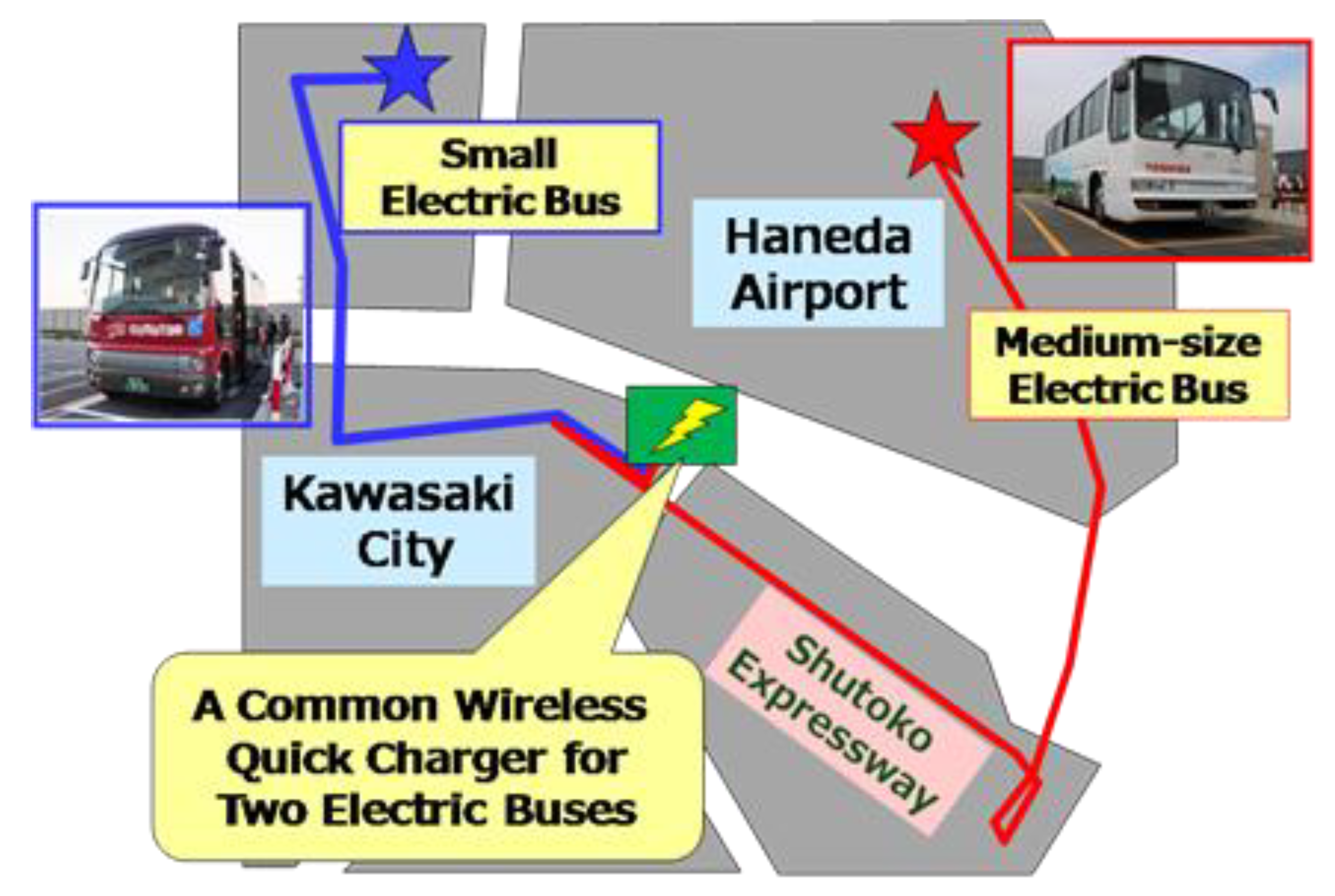
| Route | Approximately 6 km between ANA business centers in Tonomachi, Kawasaki and Higashi-Kojiya, Ota-ku, Tokyo | Approximately 11 km between ANA business centers in Tonomachi, Kawasaki and Haneda Airport |
| Frequency | 4 round trips a day | 3 round trips a day |
| Charge time | Approximately 15 minutes | Approximately 20 minutes |
| Passengers | ANA Group employees | |
| Effect of CO2 emission reduction | 42% | 60% |
© 2019 by the authors. Licensee MDPI, Basel, Switzerland. This article is an open access article distributed under the terms and conditions of the Creative Commons Attribution (CC BY) license (http://creativecommons.org/licenses/by/4.0/).
Share and Cite
Obayashi, S.; Shijo, T.; Suzuki, M.; Moritsuka, F.; Ogawa, K.; Ogura, K.; Kanekiyo, Y.; Ishida, M.; Takanaka, T.; Tada, N.; et al. 85 kHz Band 44 kW Wireless Rapid Charging System for Field Test and Public Road Operation of Electric Bus. World Electr. Veh. J. 2019, 10, 26. https://doi.org/10.3390/wevj10020026
Obayashi S, Shijo T, Suzuki M, Moritsuka F, Ogawa K, Ogura K, Kanekiyo Y, Ishida M, Takanaka T, Tada N, et al. 85 kHz Band 44 kW Wireless Rapid Charging System for Field Test and Public Road Operation of Electric Bus. World Electric Vehicle Journal. 2019; 10(2):26. https://doi.org/10.3390/wevj10020026
Chicago/Turabian StyleObayashi, Shuichi, Tetsu Shijo, Masatoshi Suzuki, Fumi Moritsuka, Kenichirou Ogawa, Koji Ogura, Yasuhiro Kanekiyo, Masaaki Ishida, Toru Takanaka, Nobumitsu Tada, and et al. 2019. "85 kHz Band 44 kW Wireless Rapid Charging System for Field Test and Public Road Operation of Electric Bus" World Electric Vehicle Journal 10, no. 2: 26. https://doi.org/10.3390/wevj10020026
APA StyleObayashi, S., Shijo, T., Suzuki, M., Moritsuka, F., Ogawa, K., Ogura, K., Kanekiyo, Y., Ishida, M., Takanaka, T., Tada, N., Takeuchi, F., Take, S., Yamauchi, Y., Yang, W.-H., & Kamiya, Y. (2019). 85 kHz Band 44 kW Wireless Rapid Charging System for Field Test and Public Road Operation of Electric Bus. World Electric Vehicle Journal, 10(2), 26. https://doi.org/10.3390/wevj10020026