Battery Life Enhancement in a Hybrid Electrical Energy Storage System Using a Multi-Source Inverter

Abstract
:Featured Application
Abstract
1. Introduction
1.1. Comparative Analysis of Energy management system (Cost, Weight)
1.2. Overview of developed strategies in HESS (Hybrid Energy Storage System)
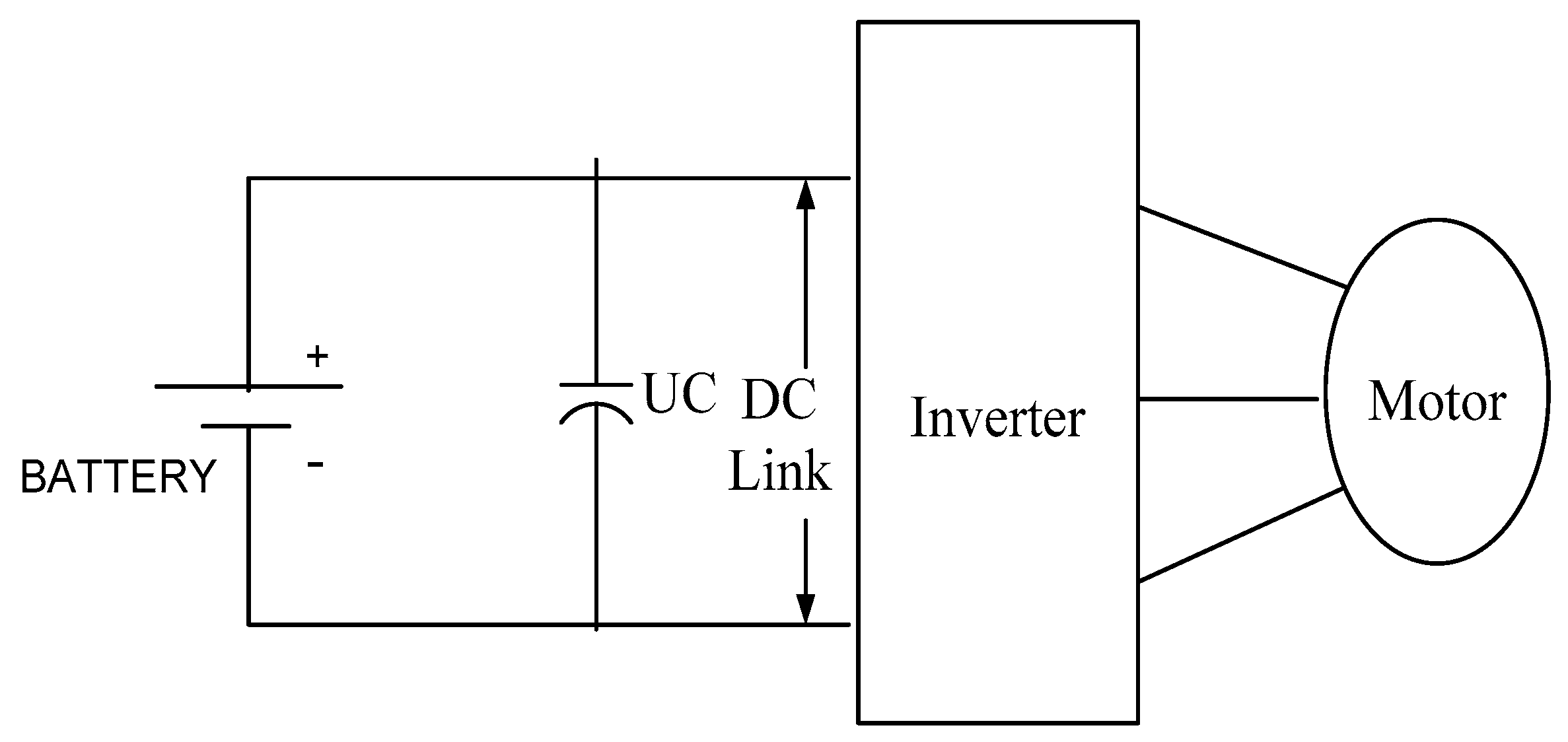
1.2.1. Passive Parallel Design
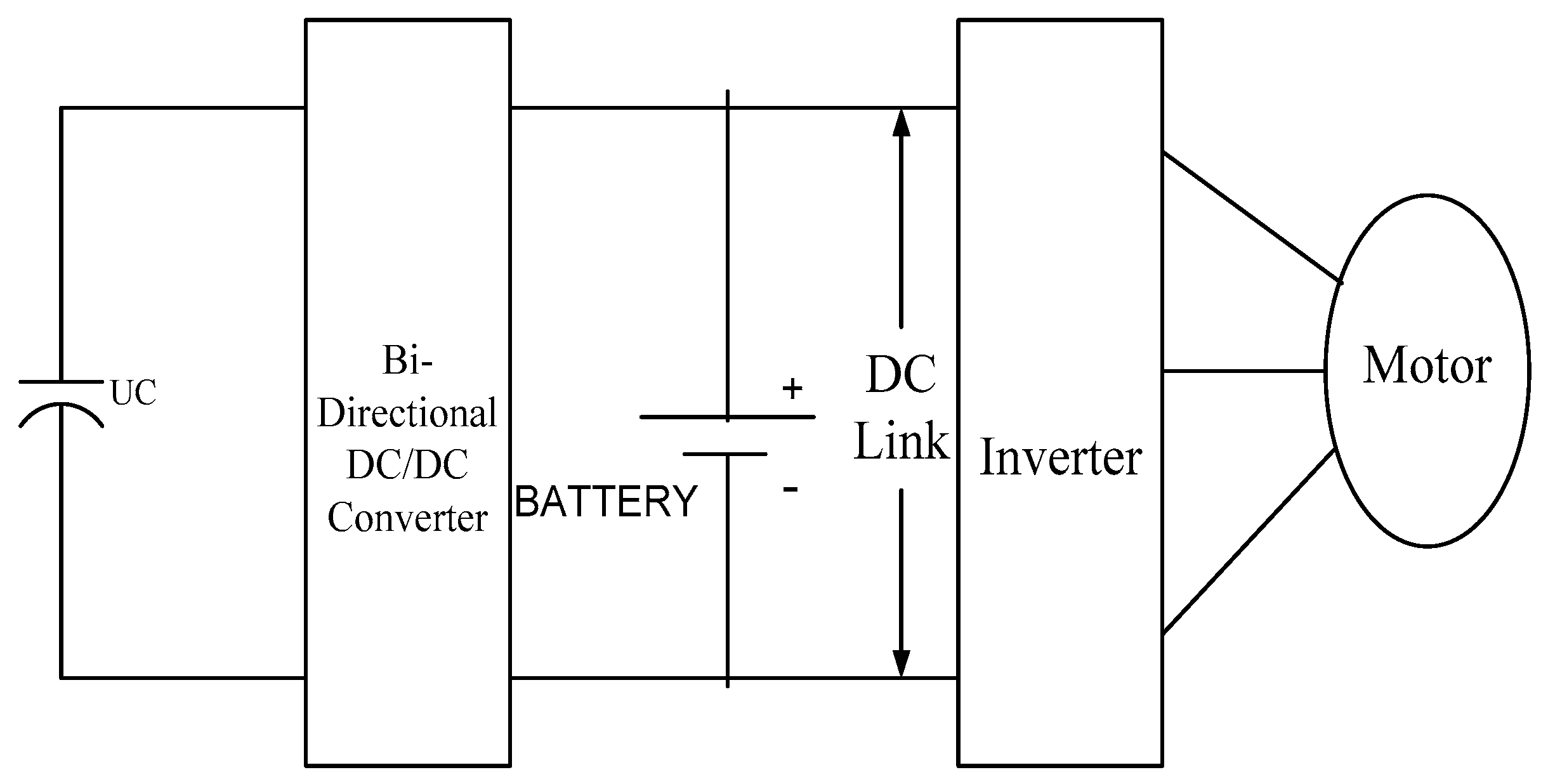
1.2.2. UC/Battery Design
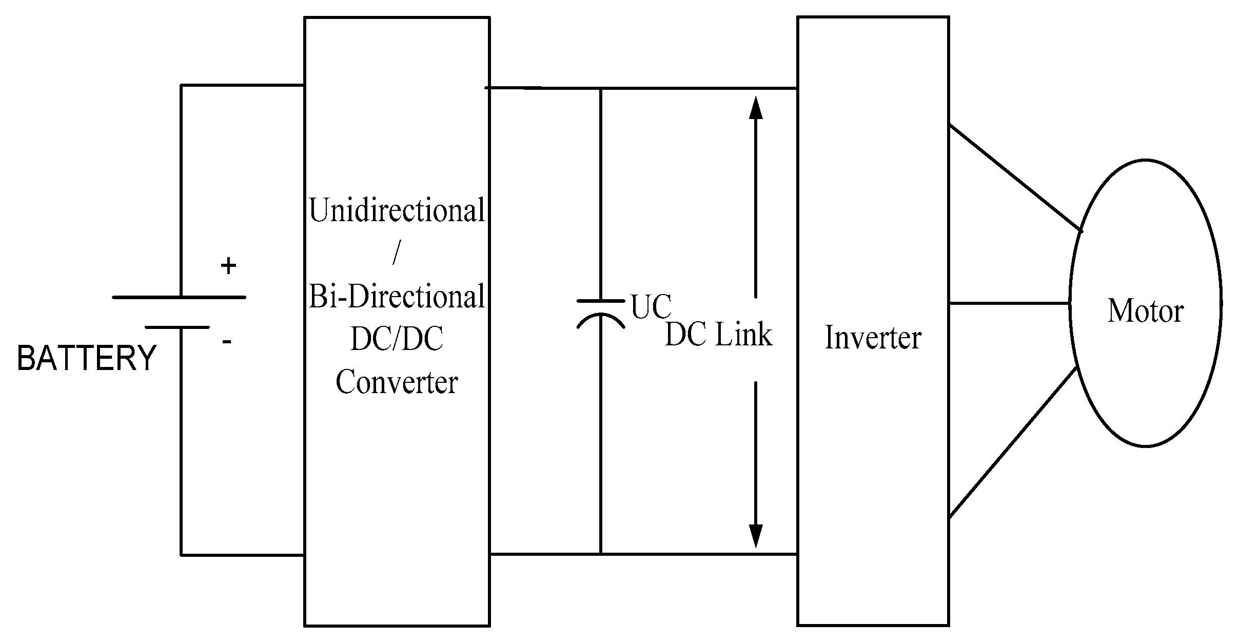
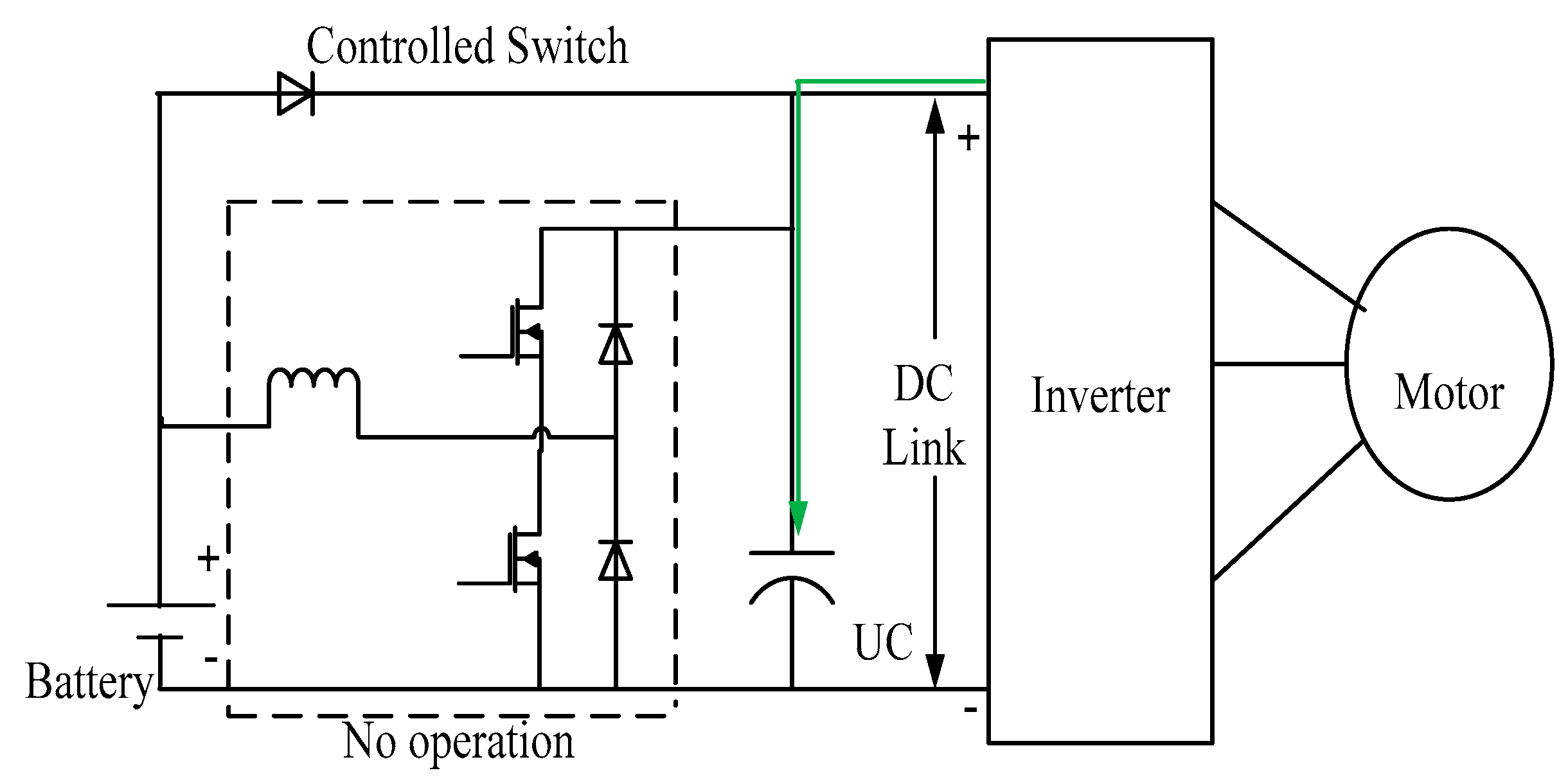
1.2.3. Battery/UC Design
Mode-1: Slow Constant Speed
Mode-2: Fast Constant Speed
Mode-3: Acceleration
Mode-4: Deceleration
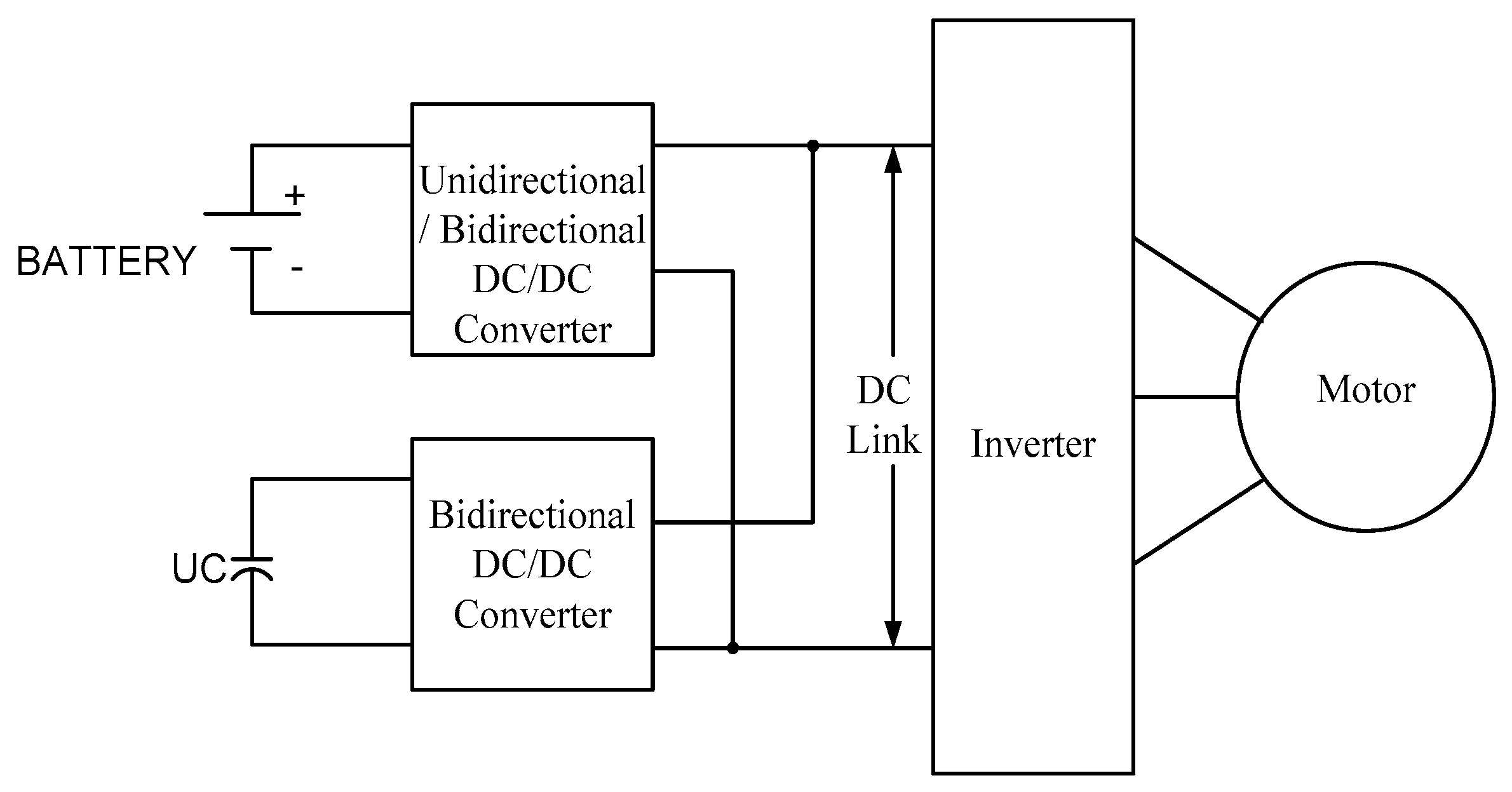
1.2.4. Multiple DC/DC Converter Design
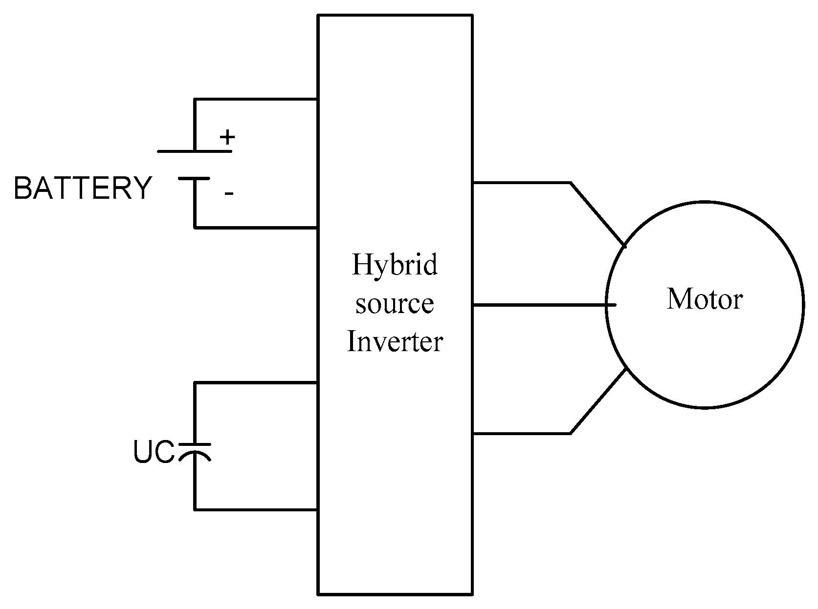
1.2.5. UC/Battery with Inverter Design
2. Materials and Methods
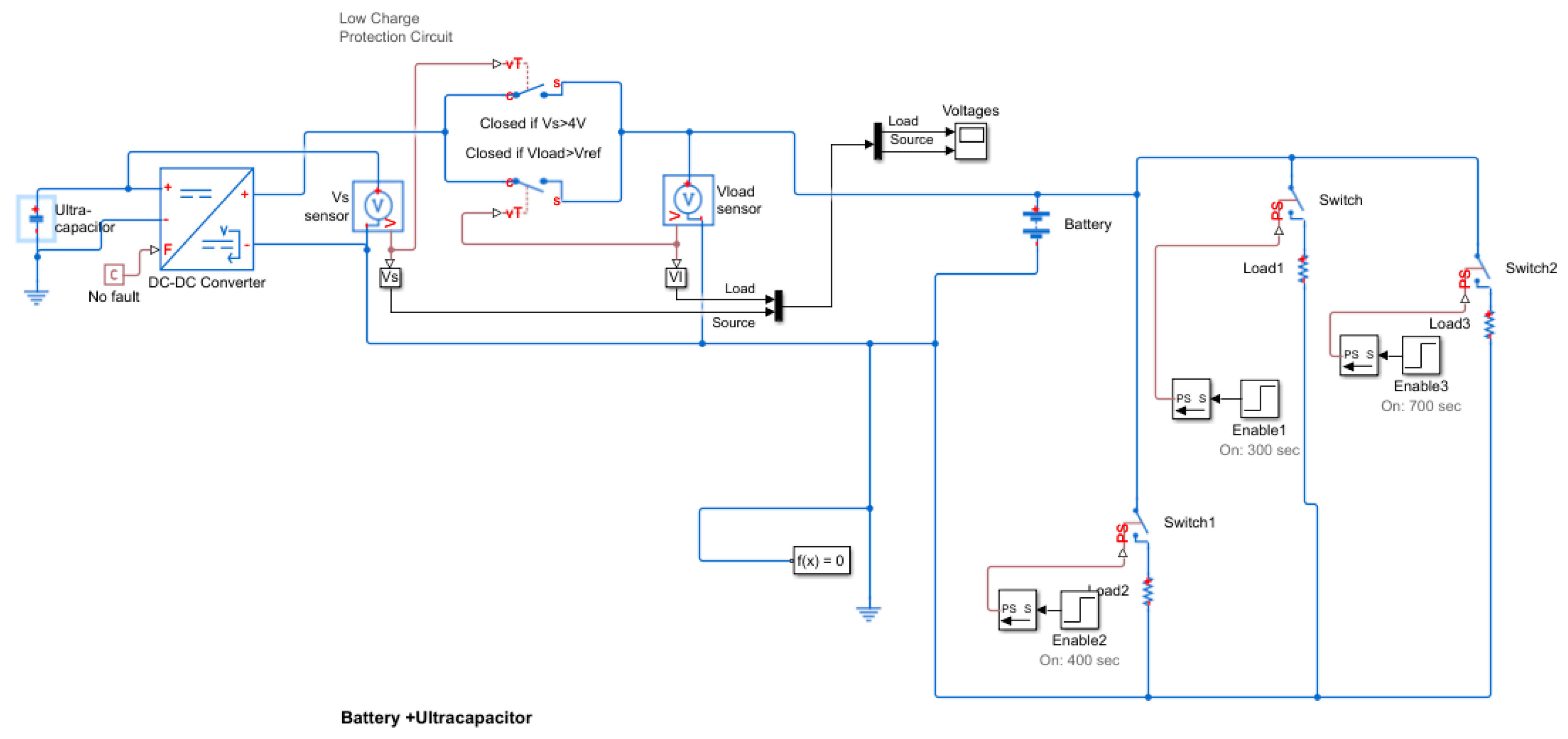
2.1. Basic Simulation Work
2.2. Proposed Work
3. Simulation Results and Discussion
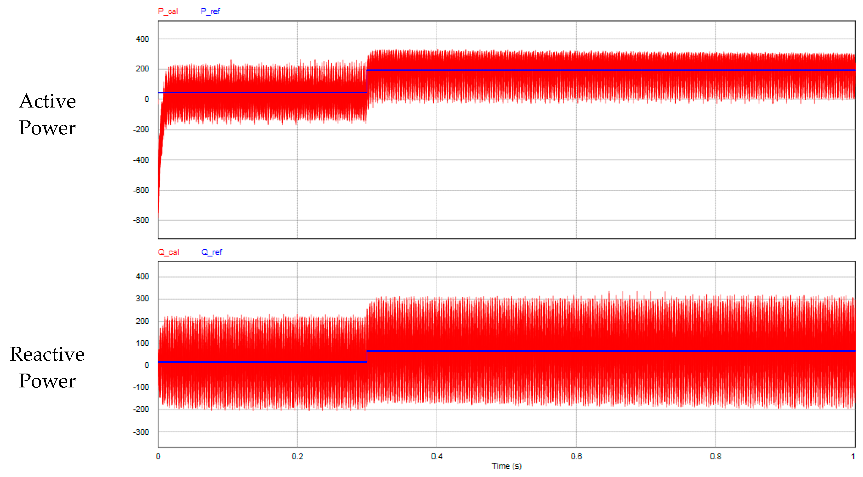
- Active power (P) with positive magnitude is the power flowing from the DC bus to the load.
- Reactive power (Q) in Var with positive magnitude is reactive power being supplied to the load.
- Bidirectional power flow in any combination is possible, where negative magnitudes inject active and reactive power from the DC bus to the load.
3.1. PSIM Simulation Results
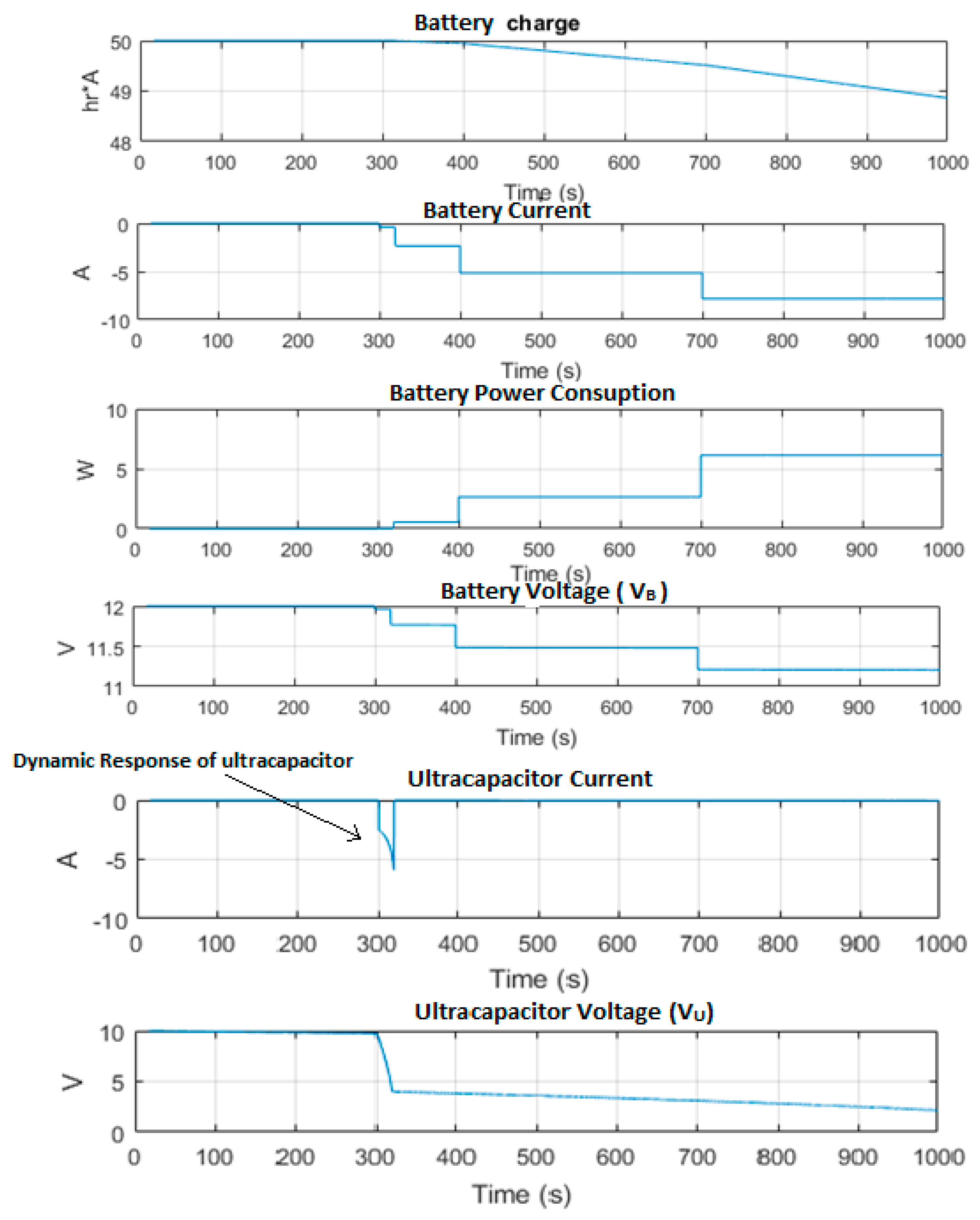
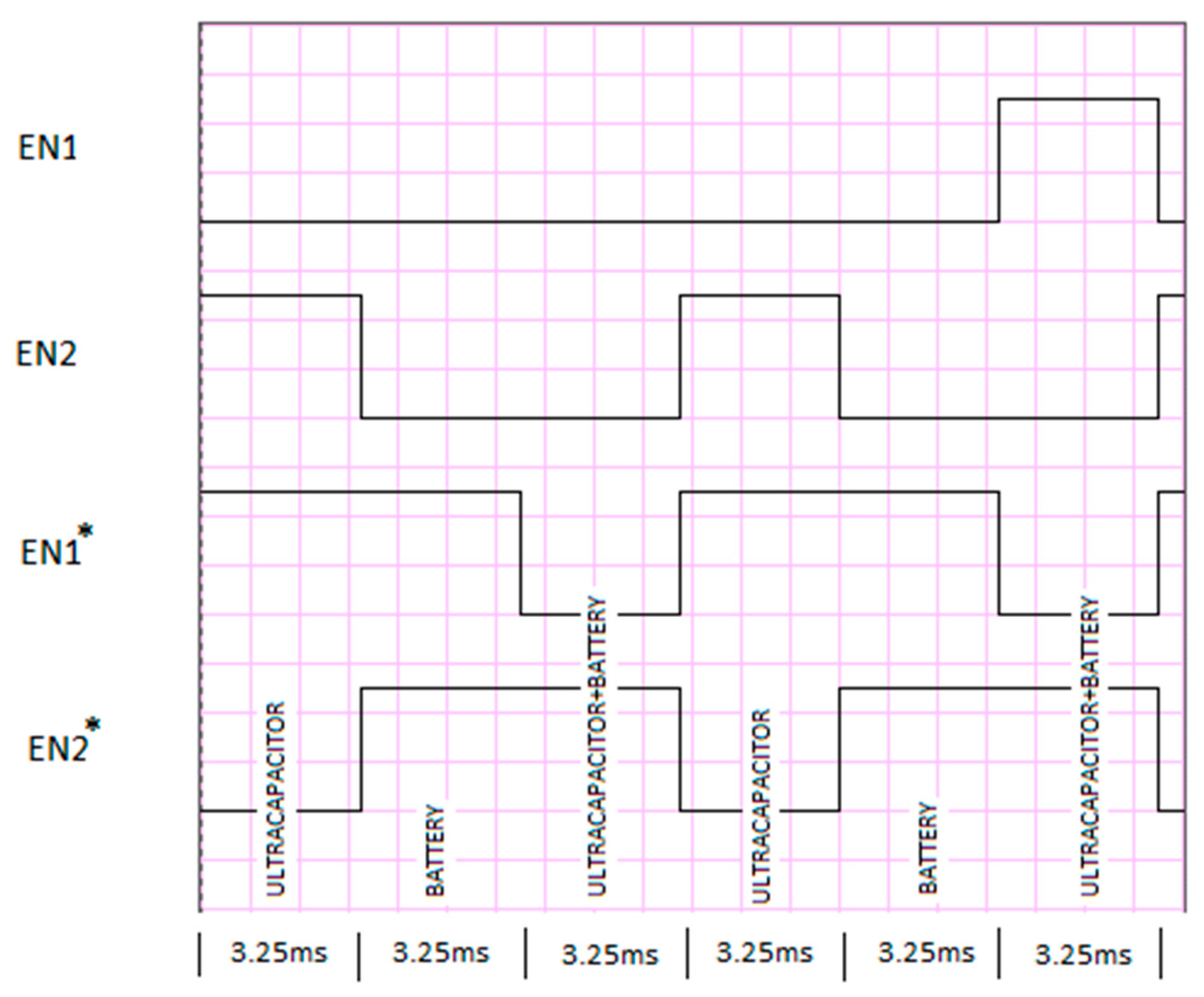
- Mode-1 (Battery and Motor or RL load): In this mode, VB drives the motor/RL load and VU is not used.
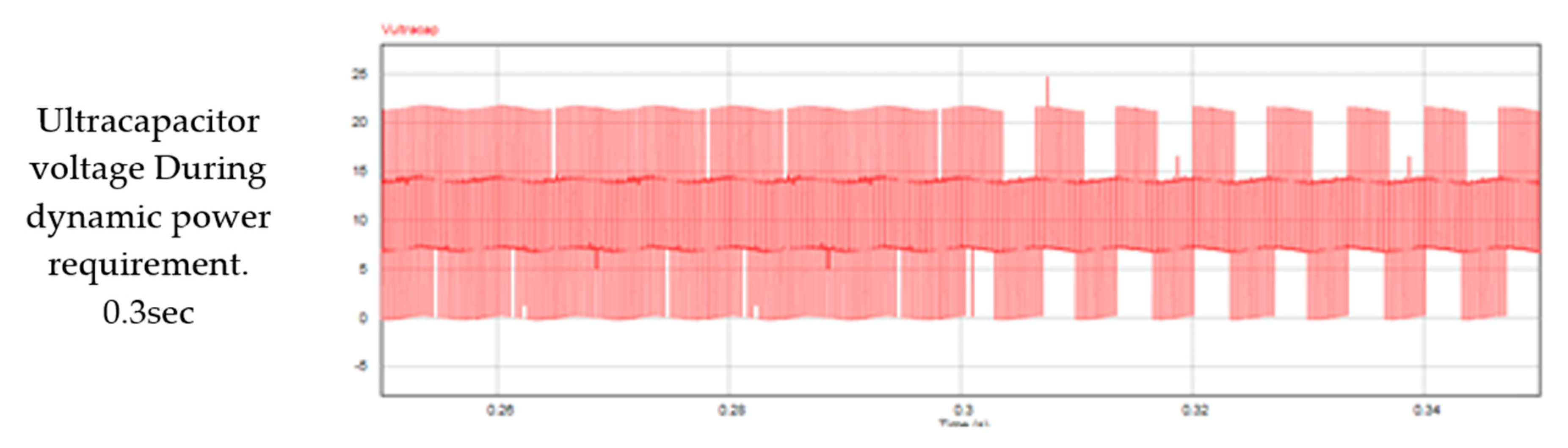
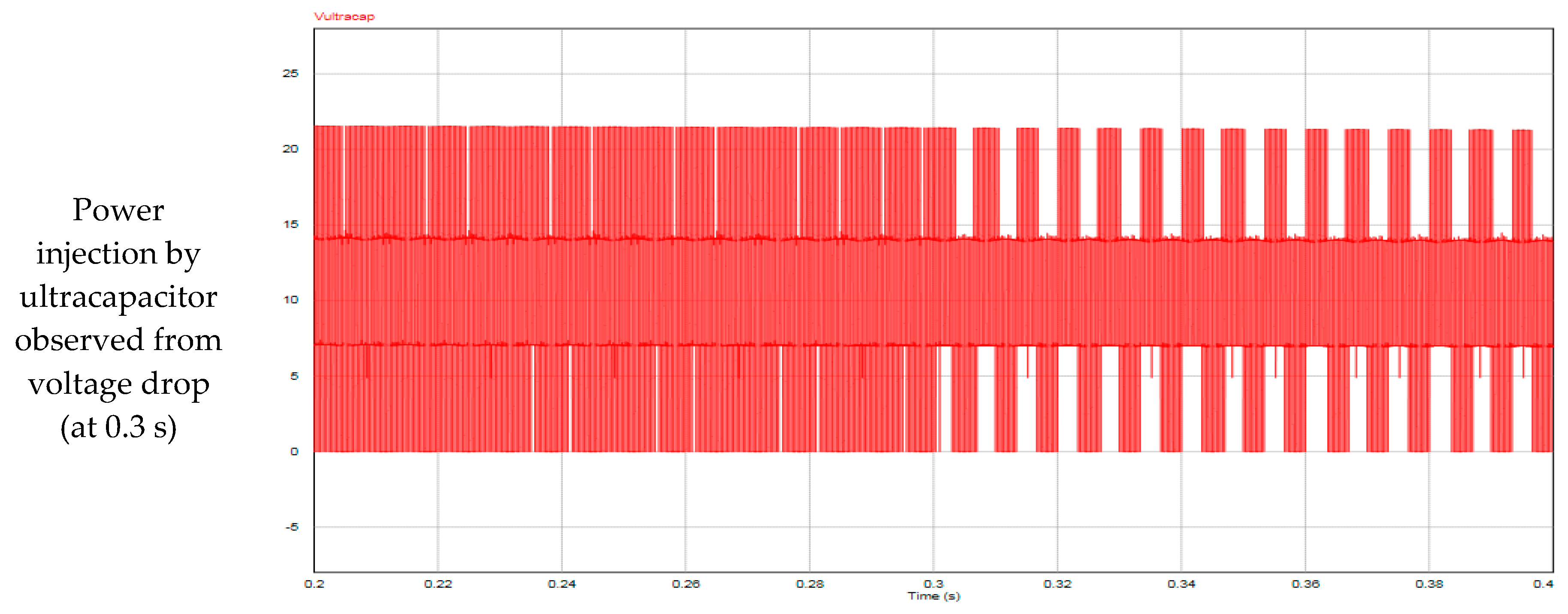
- Mode-2 (Battery, Ultracapacitor and Motor or RL load): In this mode, VB drives the load (for motor or grid) by charging the ultracapacitor (VU). The effective output voltage is equal to (VB-VU).
- Mode-3 (Ultracapacitor and Motor/ RL load): Here, VB is not used; the ultracapacitor alone (VU) drives the motor.
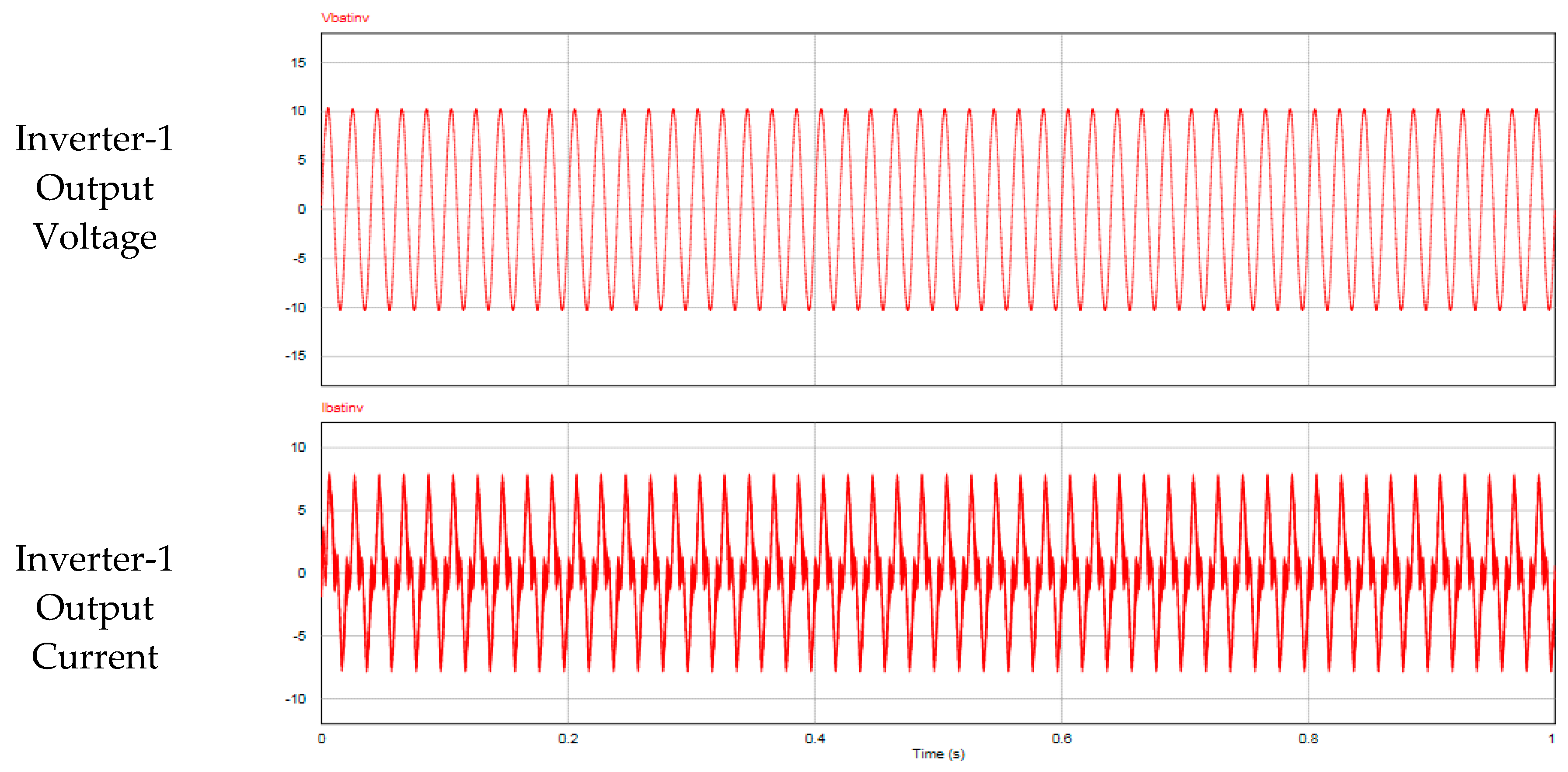
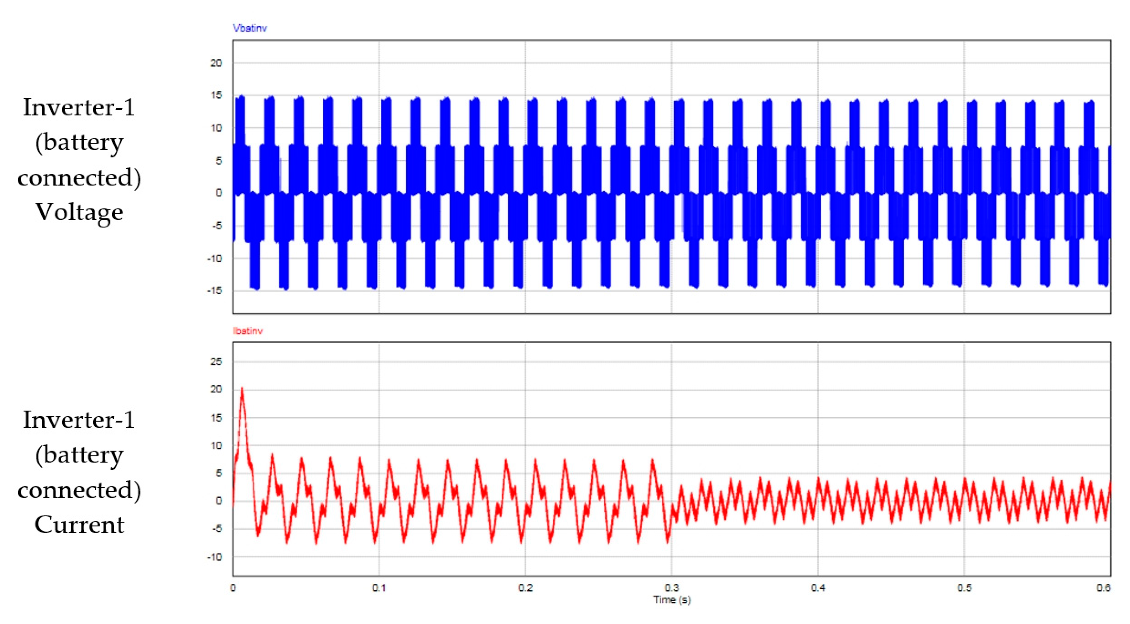
3.1.1. Mode-1 (Battery & Motor or RL Load)
3.1.2. Mode-2 (Battery, Ultracapacitor & Motor or RL Load)
3.1.3. Mode-3 (Ultracapacitor and Motor/RL Load)
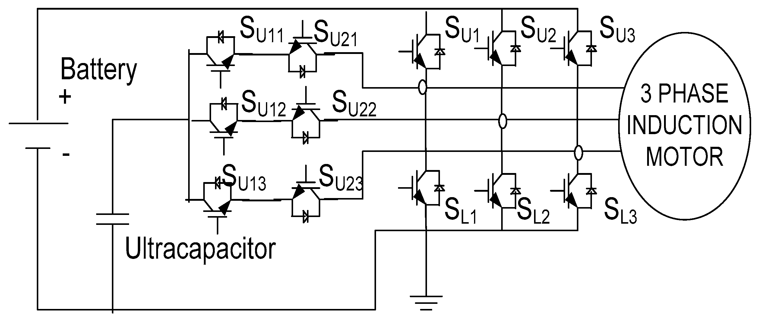
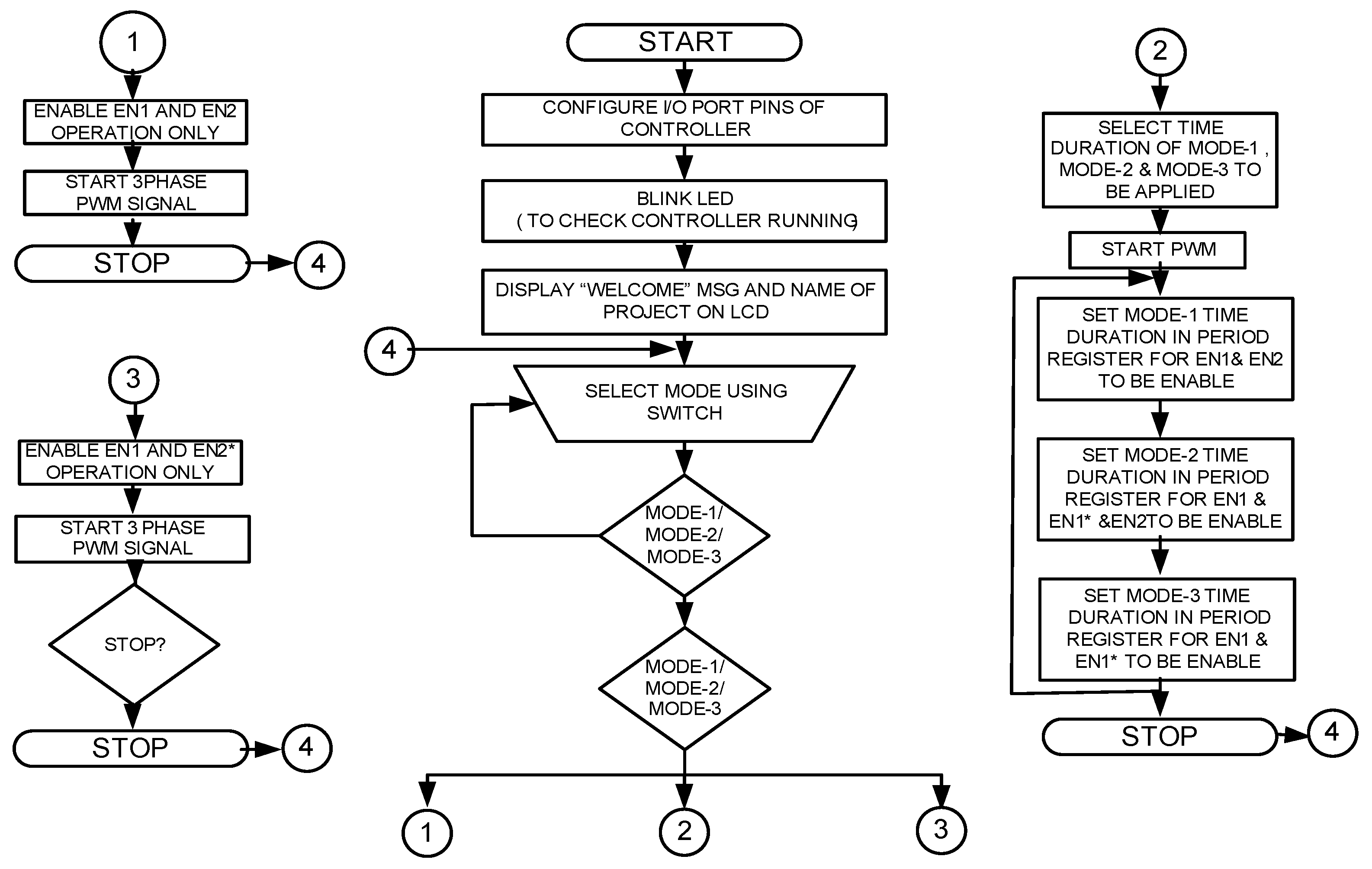
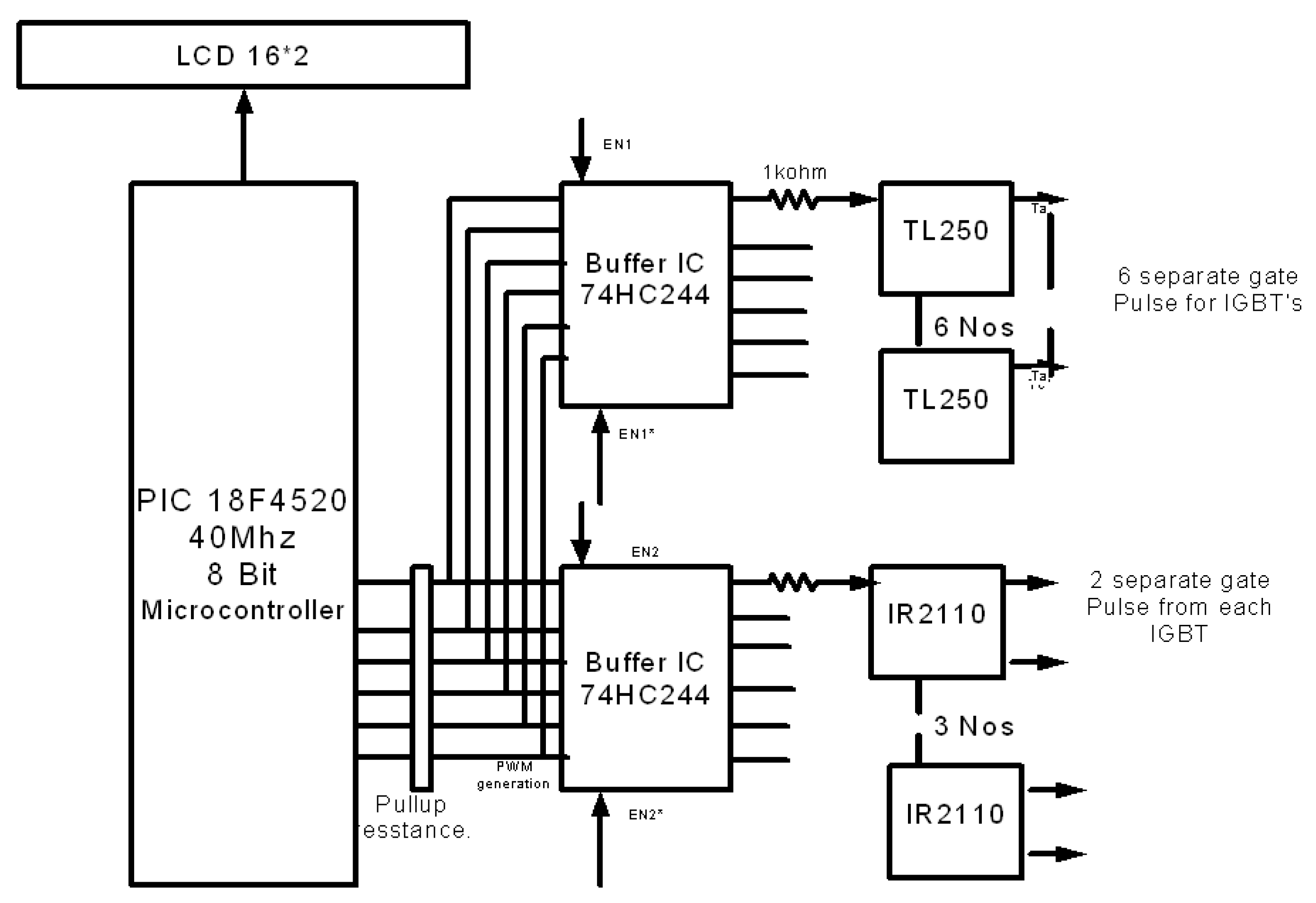
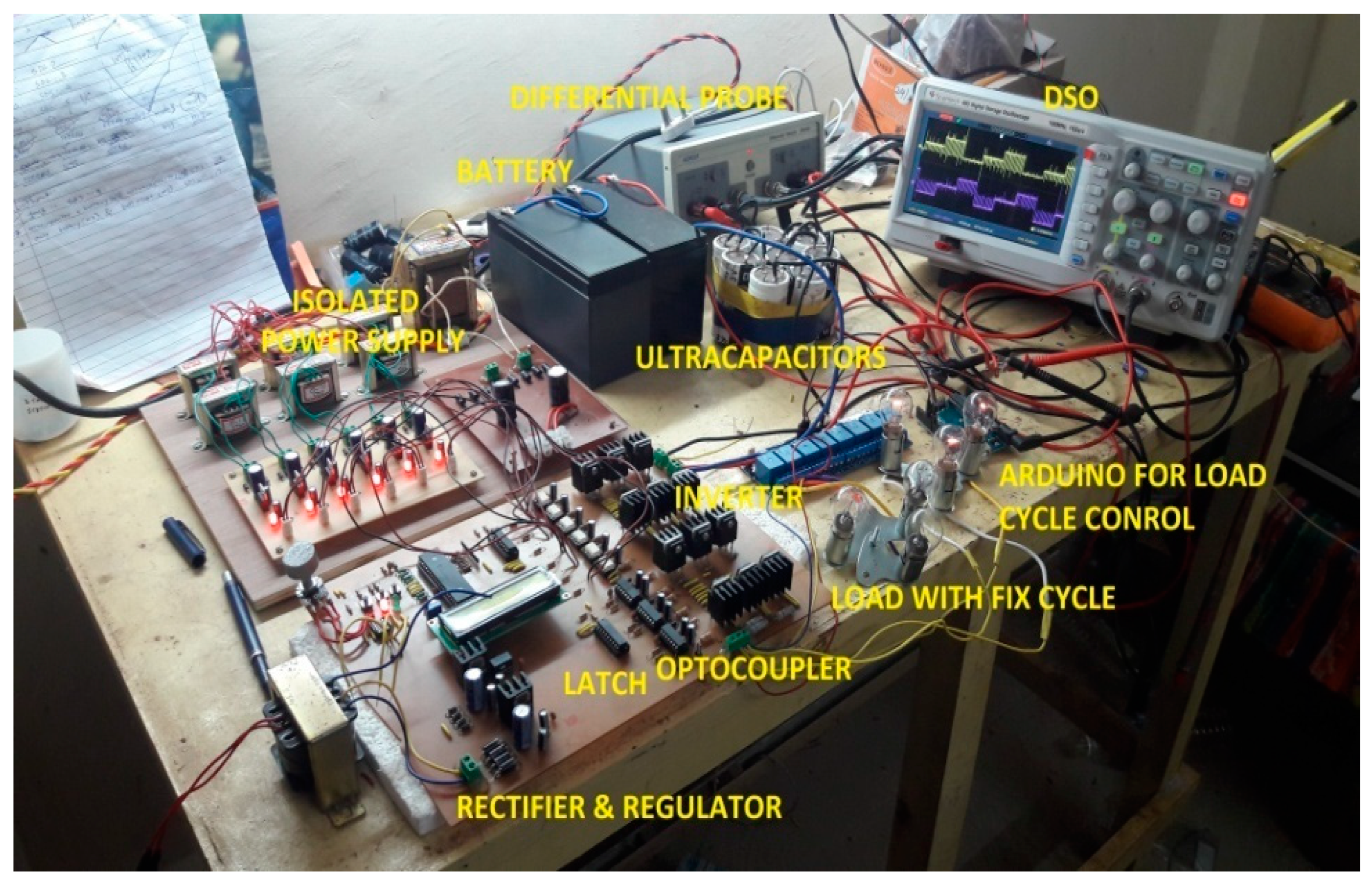
4. Hardware Implementation
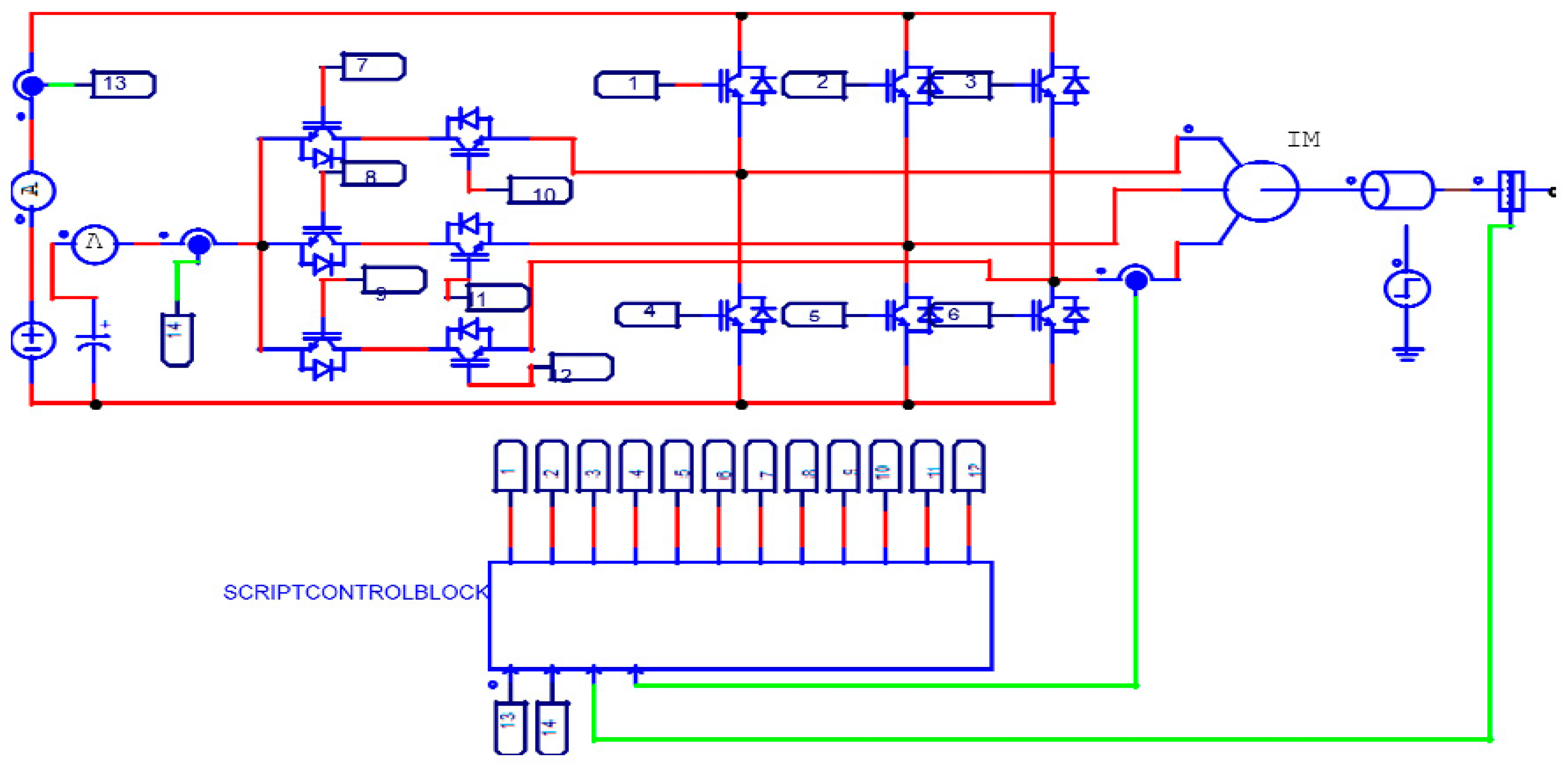
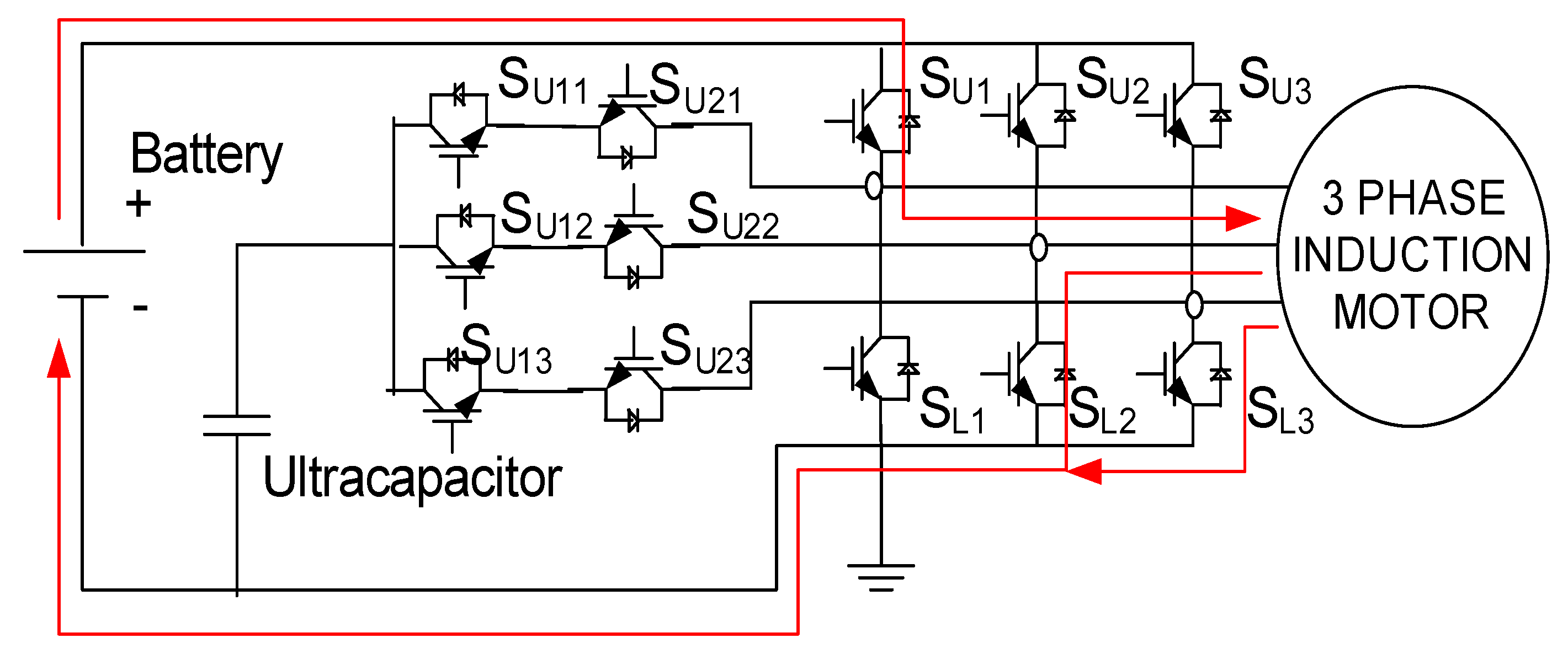
- Mode-1: The switches SU1, SU2, SU3, and SL1, SL2, SL3 enable the discharging of the battery (VB) to supply the motor (RL load); an ultra-capacitor (VU)is not used. (The ultra-capacitor is charged through the battery using switches SU21, SU22, SU23 along with switches SU1, SU2, SU3 in closed-loop control by sensing the load current and terminal voltage of the ultra-capacitor; see Figure 24).
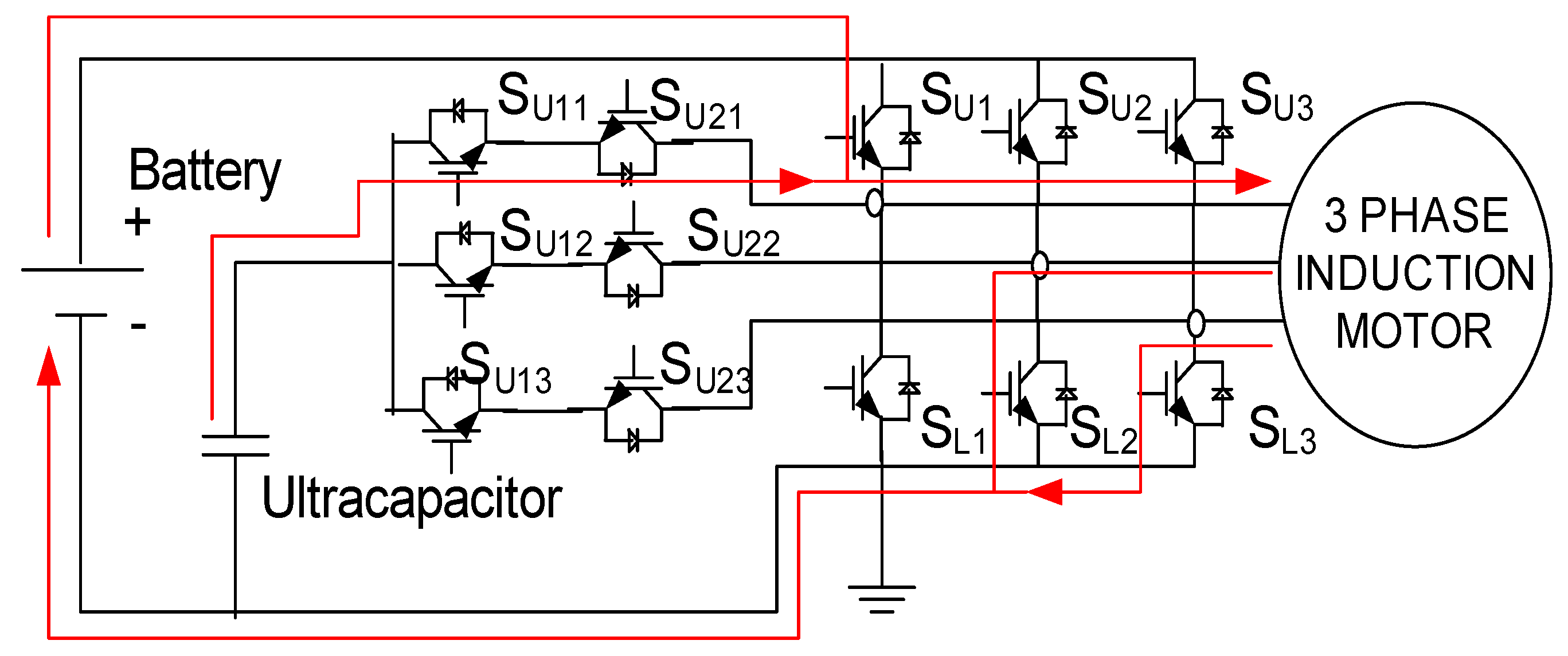
- Mode-2: The switches SU1, SU2, SU3 and SU11, SU12, SU13 enable the battery (VB) to supply the motor (RL load) with discharging ultracapacitor (VU) (Figure 25).
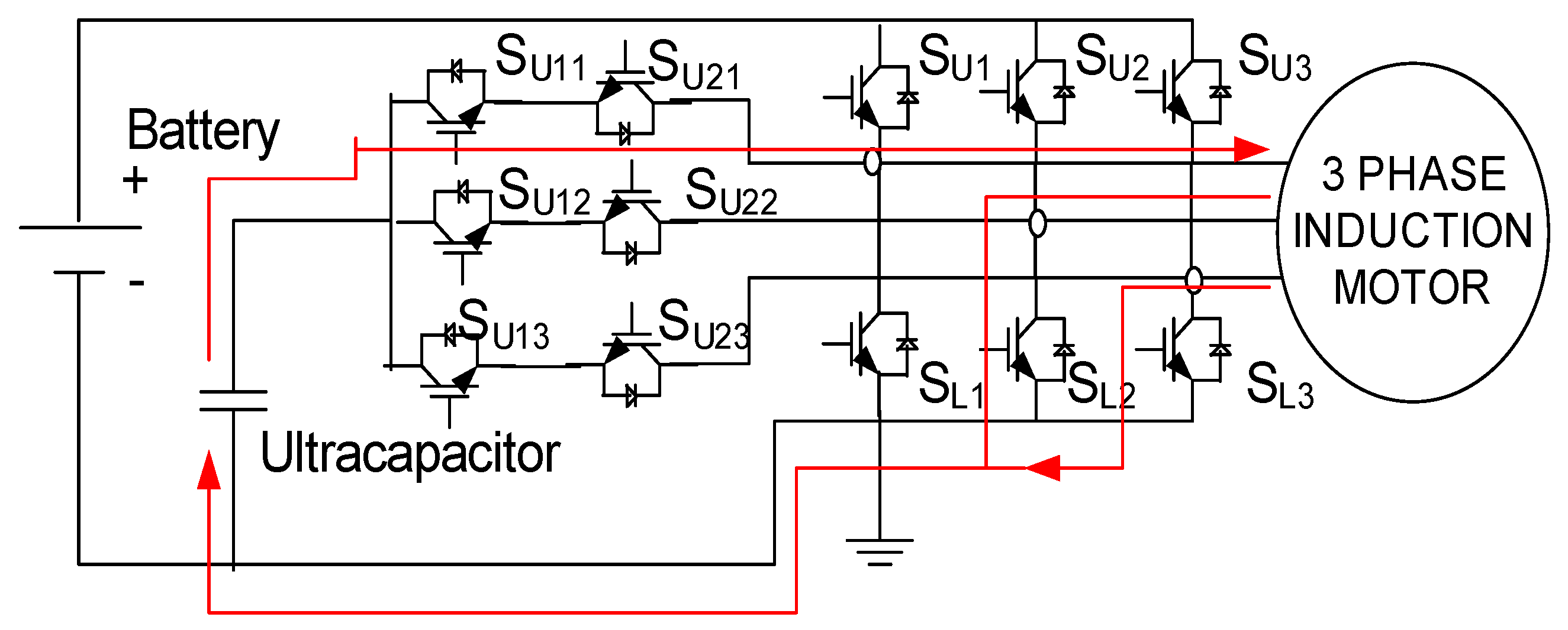
- Mode-3: The battery (VB)is not used and switches SL1, SL2, SL3, and SU11, SU12, SU13 enable the ultracapacitor (VU) to supply the motor (RL load) (Figure 26).
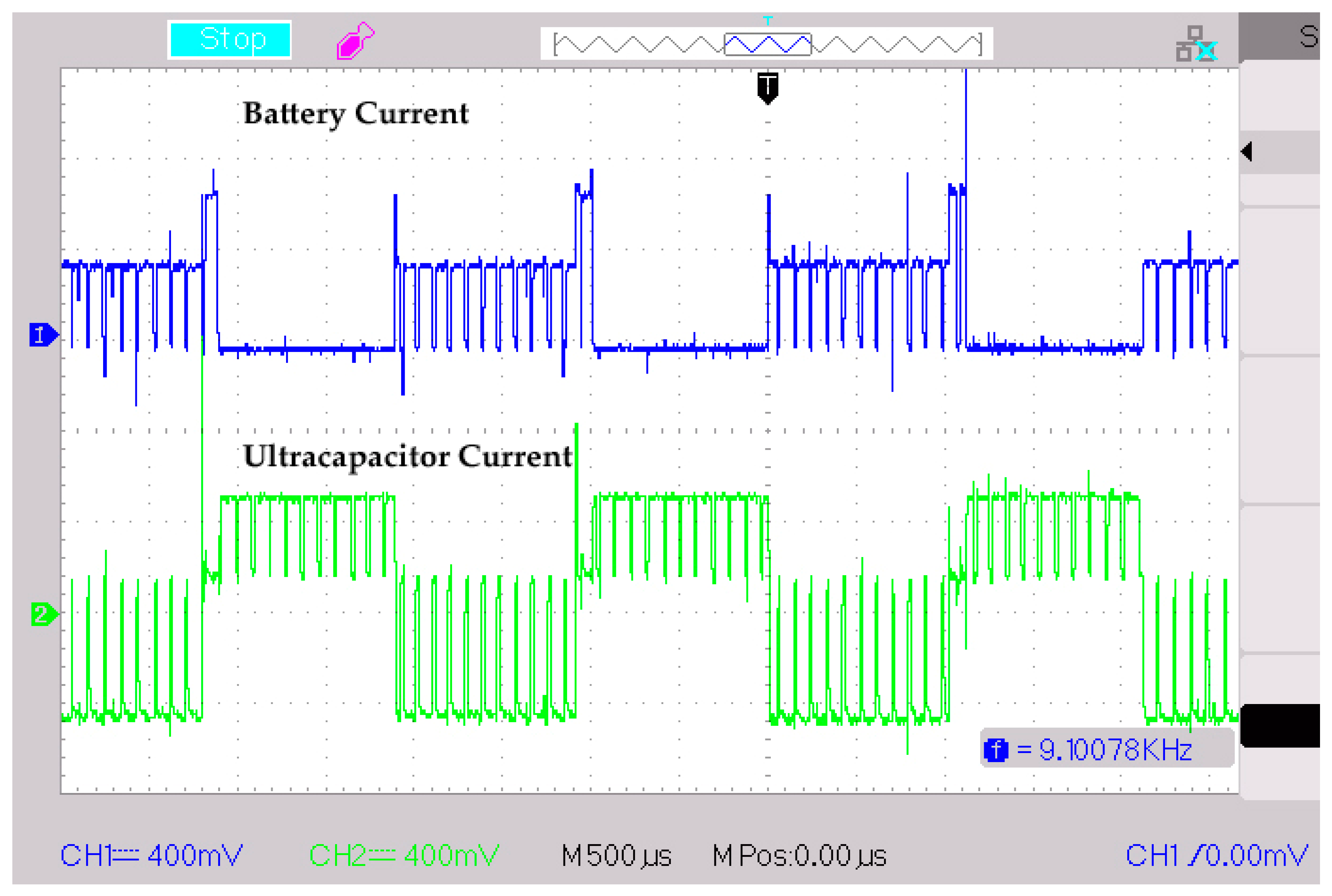
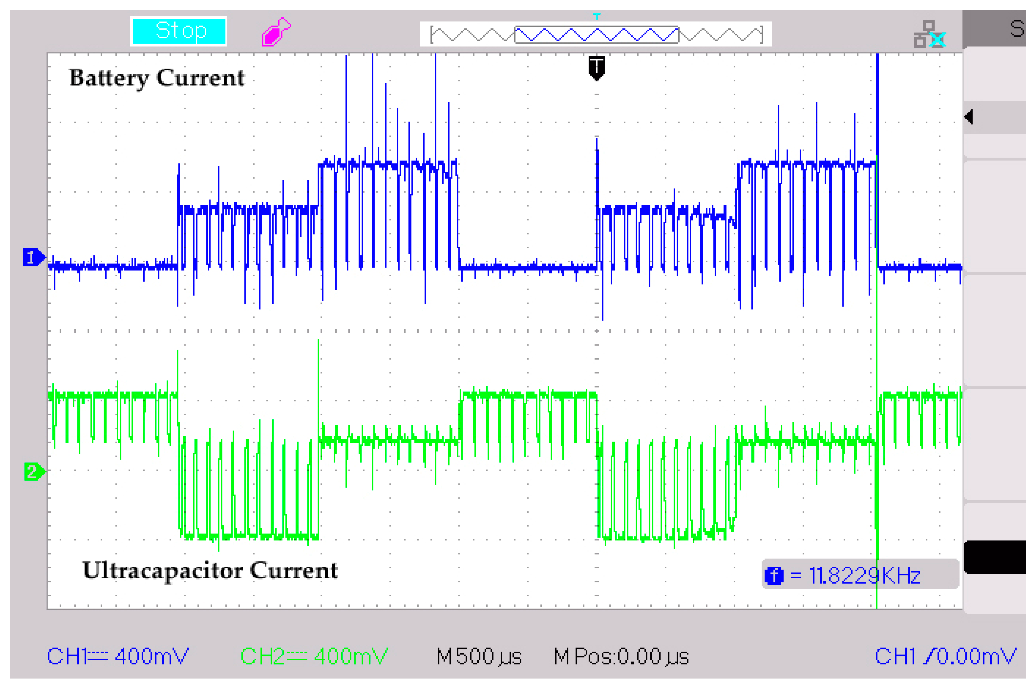
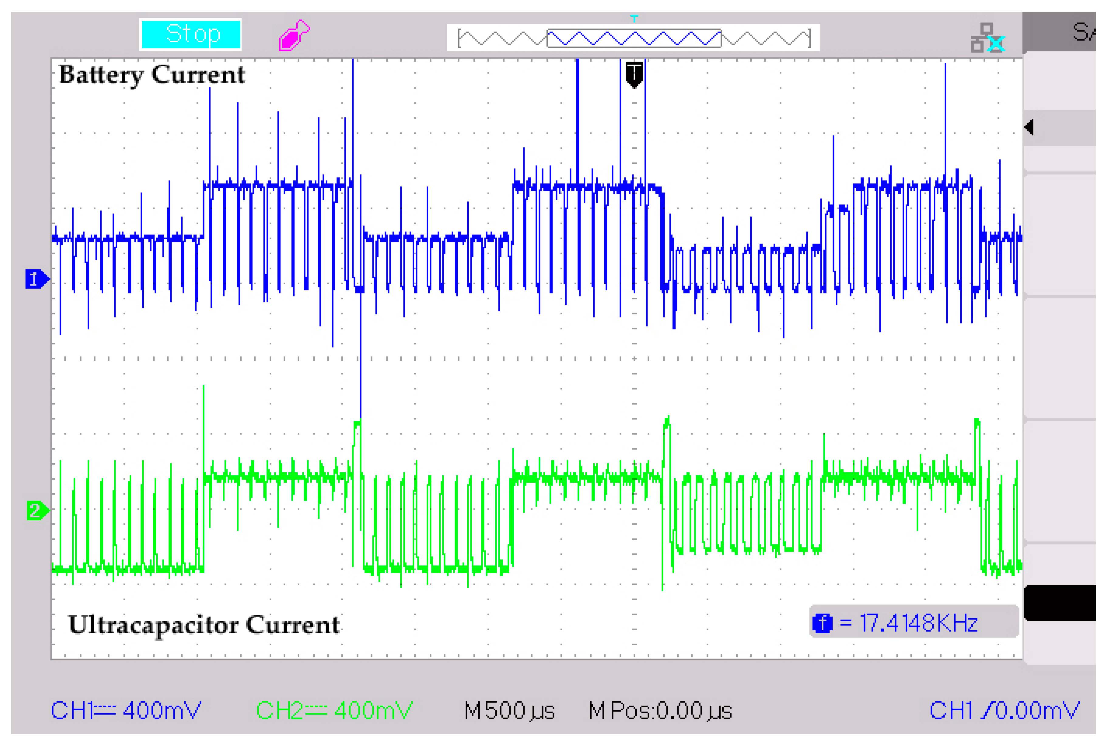
5. Results
6. Conclusions
Author Contributions
Funding
Acknowledgments
Conflicts of Interest
References
- Pereirinha, P.G.; Trovão, J.P. Multiple Energy Sources Hybridization: The Future of Electric Vehicles? Chapter 8. In New Generation of Electric Vehicles; IntechOpen: London, UK, 2012; pp. 237–262. [Google Scholar] [CrossRef]
- Burke, A.F. Batteries and Ultracapacitors for Electric, Hybrid, and Fuel Cell Vehicles. Proc. IEEE 2007, 95, 806–820. [Google Scholar] [CrossRef]
- Sauer, D.U.; Kleimaier, M.; Glaunsinger, W. Relevance of energy storage in future distribution networks with high penetration of renewable energy sources. In Proceedings of the CIRED 2009 20th International Conference and Exhibition on Electricity Distribution, Prague, Czech Republic, 8–11 June 2009; pp. 1–4. [Google Scholar]
- Akatsu, K.; Watanabe, N.; Fujitsuna, M.; Doki, S.; Fujimoto, H. Recent Related Technologies for EV/HEV Applications in Japan. In Proceedings of the IEEE ECCE Asia Downunder, Melbourne, Australia, 3–6 June 2013; pp. 141–146. [Google Scholar]
- Lukic, S.M.; Cao, J.; Bansal, R.C.; Rodriguez, F.; Emadi, A. Energy Storage Systems for Automotive Applications. IEEE Trans. Ind. Electron. 2008, 55, 2258–2267. [Google Scholar] [CrossRef]
- Somayajula, D.; Crow, M.L. An Integrated Active Power Filter–Ultracapacitor Design to Provide Intermittency Smoothing and Reactive Power Support to the Distribution Grid. IEEE Trans. Sustain. Energy 2014, 5, 1116–1125. [Google Scholar] [CrossRef]
- Manfredi, S.; Paganm, M.; Raimo, R. Ultracapacitor-based Distributed Energy Resources to support time-varying smart-grid power flows. In Proceedings of the International Symposium on Power Electronics, Electrical Drives, Automation and Motion, Sorrento, Italy, 20–22 June 2012; pp. 1148–1153. [Google Scholar]
- Li, X.; Zhang, L.; Wang, Z.; Dong, P. Remaining useful life prediction for lithium-ion batteries based on a hybrid model combining the long short-term memory and Elman neural networks. J. Energy Storage 2019, 21, 510–518. [Google Scholar] [CrossRef]
- Zhang, J.; Zhang, L.; Sun, F.; Wang, Z. An Overview on Thermal Safety Issues of Lithium-ion Batteries for Electric Vehicle Application. IEEE Access 2018, 6, 23848–23863. [Google Scholar] [CrossRef]
- Li, X.; Wang, Z.; Zhang, L.; Zou, C.; Dorrell, D.D. State-of-health estimation for Li-ion batteries by combing the incremental capacity analysis method with grey relational analysis. J. Power Sources 2019, 410–411, 106–114. [Google Scholar] [CrossRef]
- Wang, Z.; Ma, J.; Zhang, L. State-of-health estimation for lithium-ion batteries based on the multi-island genetic algorithm and the gaussian process regression. IEEE Access 2017, 5, 21286–21295. [Google Scholar] [CrossRef]
- Zhang, L.; Hu, X.; Wang, Z.; Sun, F.; Deng, J.; Dorrell, D. Multi-objective optimal sizing of hybrid energy storage system for electric vehicles. IEEE Trans. Veh. Technol. 2018, 67, 1027–1035. [Google Scholar] [CrossRef]
- Aharon, I.; Kuperman, A. Topological Overview of Powertrains for Battery-Powered Vehicles with Range Extenders. IEEE Trans. Power Electron. 2011, 26, 868–876. [Google Scholar] [CrossRef]
- Schupbach, R.M.; Balda, J.C.; Zolot, M.; Kramer, B. Design methodology of a combined battery-ultracapacitor energy storage unit for vehicle power management. In Proceedings of the IEEE 34th Annual Conference on Power Electronics Specialist (PESC 03), Acapulco, Mexico, 15–19 June 2003. [Google Scholar]
- Emadi, A.; Rajashekara, K.; Williamson, S.S.; Lukic, S.M. Topological Overview of Hybrid Electric and Fuel Cell Vehicular Power System Architectures and Configurations. IEEE Trans. Veh. Technol. 2005, 54, 763–770. [Google Scholar] [CrossRef]
- Cao, J.; Emadi, A. A new battery/ultracapacitor hybrid energy storage system for electric, hybrid, and plug-in hybrid electric vehicles. IEEE Trans. Power Electron. 2012, 27, 122–132. [Google Scholar]
- Lukic, S.M.; Wirasingha, S.G.; Rodriguez, F.; Jian, C.; Emadi, A. Power management of an ultracapacitor/battery hybrid energy storage system in an HEV. In Proceedings of the 2006 IEEE Vehicle Power and Propulsion Conference, Windsor, UK, 6–8 September 2006; pp. 1–6. [Google Scholar]
- Dorn-Gomba, L.; Magne, P.; Danen, B.; Emadi, A. On the concept of the multi-source inverter for hybrid electric vehicle powertrains. IEEE Trans. Power Electron. 2018, 33, 7376–7386. [Google Scholar] [CrossRef]
- Dorn-Gomba, L.; Emadi, A. A novel Hybrid Energy Storage System Using the Multi Source Invereter. In Proceedings of the 2018 IEEE Applied Power Electronics Conference and Exposition (APEC), San Antonio, TX, USA, 4–8 March 2018. [Google Scholar]
- Soltani, M.; Ronsmans, J.; Kakihara, S.; Jaguemont, J.; Van den Bossche, P.; Van Mierlo, J.; Omar, N. Hybrid Battery/Lithium-Ion Capacitor Energy Storage System for a Pure Electric Bus for an Urban Transportation Application. Appl. Sci. 2018, 8, 1176. [Google Scholar] [CrossRef]
- Xiangjun, L.; Liangfei, X.; Jianfeng, H.; Jianqiu, L.; Minggao, O. Regenerative braking control strategy for fuel cell hybrid vehicles using fuzzy logic. In Proceedings of the International Conference on Electrical Machines and Systems, Wuhan, China, 17–20 October 2008; pp. 2712–2716. [Google Scholar]
- Wu, X.; Wang, T. Optimization of Battery Capacity Decay for Semi-Active Hybrid Energy Storage System Equipped on Electric City Bus. Energies 2017, 10, 792. [Google Scholar] [CrossRef]
- Xiangjun, L.; Liangfei, X.; Jianfeng, H.; Jianqiu, L.; Minggao, O. Control algorithm of fuel cell/battery hybrid vehicular power system. In Proceedings of the IEEE Vehicle Power and Propulsion Conference, Harbin, Hei Longjiang, China, 3–5 September 2008; pp. 1–6. [Google Scholar]
- Jiya, I.N.; Gurusinghe, N.; Gouws, R. Combination of LiCs and EDLCs with Batteries: A New Paradigm of Hybrid Energy Storage for Application in EVs. World Electr. Veh. J. 2018, 9, 47. [Google Scholar] [CrossRef]
- Miñambres-Marcos, V.M.; Guerrero-Martínez, M.Á.; Barrero-González, F.; Milanés-Montero, M.I. A Grid Connected Photovoltaic Inverter with Battery-Supercapacitor Hybrid Energy Storage. Sensors 2017, 17, 1856. [Google Scholar] [CrossRef] [PubMed]
- Liu, J.; Jin, T.; Liu, L.; Chen, Y.; Yuan, K. Multi-Objective Optimization of a Hybrid ESS Based on Optimal Energy Management Strategy for LHDs. Sustainability 2017, 9, 1874. [Google Scholar] [CrossRef]
- Jiuyu, D.; Minggao, O.; Wang, H. Battery electric vehicle parameters design targeting to cost-benefit objective. In Proceedings of the IEEE Vehicle Power and Propulsion Conference, Seoul, Korea, 9–12 October 2012; pp. 1160–1164. [Google Scholar]
- Trovão, J.P.; Jorge, H.M.; Pereirinha, P.G. Design Methodology of Energy Storage Systems for a Small Electric Vehicle. In Proceedings of the EVS24, Stavanger, Norway, 13–16 May 2009. [Google Scholar]
- Trovao, J.P.F.; Santos, V.D.N.; Antunes, C.H.; Pereirinha, P.G.; Jorge, H.M. A real-time energy management architecture for multisource electric vehicles. IEEE Trans. Ind. Electron. 2015, 62, 3223–3233. [Google Scholar] [CrossRef]


| Sr. No. | Storage Element | Specific Energy Density (Wh/Kg) | Energy Density (Wh/Ltr) | Power Density (W/kg) | Cycle/Life |
|---|---|---|---|---|---|
| 1 | Lead Acid Battery | 40 | 80 | 100 | 1000 |
| 2 | Ni-MH | 80 | 200 | 100 to 250 | 2000 |
| 3 | High-energy Li-Ion | 77 | 250 | 750 to 1500 | 2000 |
| 4 | Ultra-capacitor | 4.5 | 6.4 | 2000 | 500,000 |
| Specifications | Battery (EME LIR18650) | Ultracapacitor (Maxwell BCAP0650) |
|---|---|---|
| Rated Capacity | - | 650 F |
| Rated Voltage | 3.7 Volt | 2.70 V |
| Mass Typical | 46 g | 160 g |
| Specific Power | 1500 W/kg | 6800 W/kg |
| Specific Energy | 265 Wh/kg | 4.1 Wh/kg |
| Life | 5–10 years | 10 to 15 years |
| Cost | $224/kW | $500/kW |
| EMS Using Battery | EMS Using Ultracapacitor | EMS using Battery and Ultracapacitor (Hybrid EMS) | ||||
|---|---|---|---|---|---|---|
| Weight (Kg) | Cost ($) | Weight (Kg) | Cost ($) | Wt (Kg) | Cost ($) | |
| UC pack | - | - | 150 × 1000/6800 | 150 × 500 | 30 × 1000/6800 | 30 × 500 |
| Battery Pack | 150 × 1000/1500 | 150 × 224 | - | - | 120 × 1000/1500 | 120 × 224 |
| Total | 100 | 33,600 | 22.05 | 75,000 | UC = 4.41 kg + Battery = 80 kg = 84.41 kg | 1500 + 26880 = 28,380 |
| Control State | EN1 (SU1, SU2, SU3) | EN2 (SL1, SL2, SL3) | EN1 * (SU11, SU12, SU13) | EN2 * (SU21, SU22, SU23) |
|---|---|---|---|---|
| UC (Charging) | ON | OFF | OFF | ON |
| Battery (Discharging) | ON | ON | OFF | OFF |
| Battery (Discharging) + UC (Discharging) | ON | ON | ON | OFF |
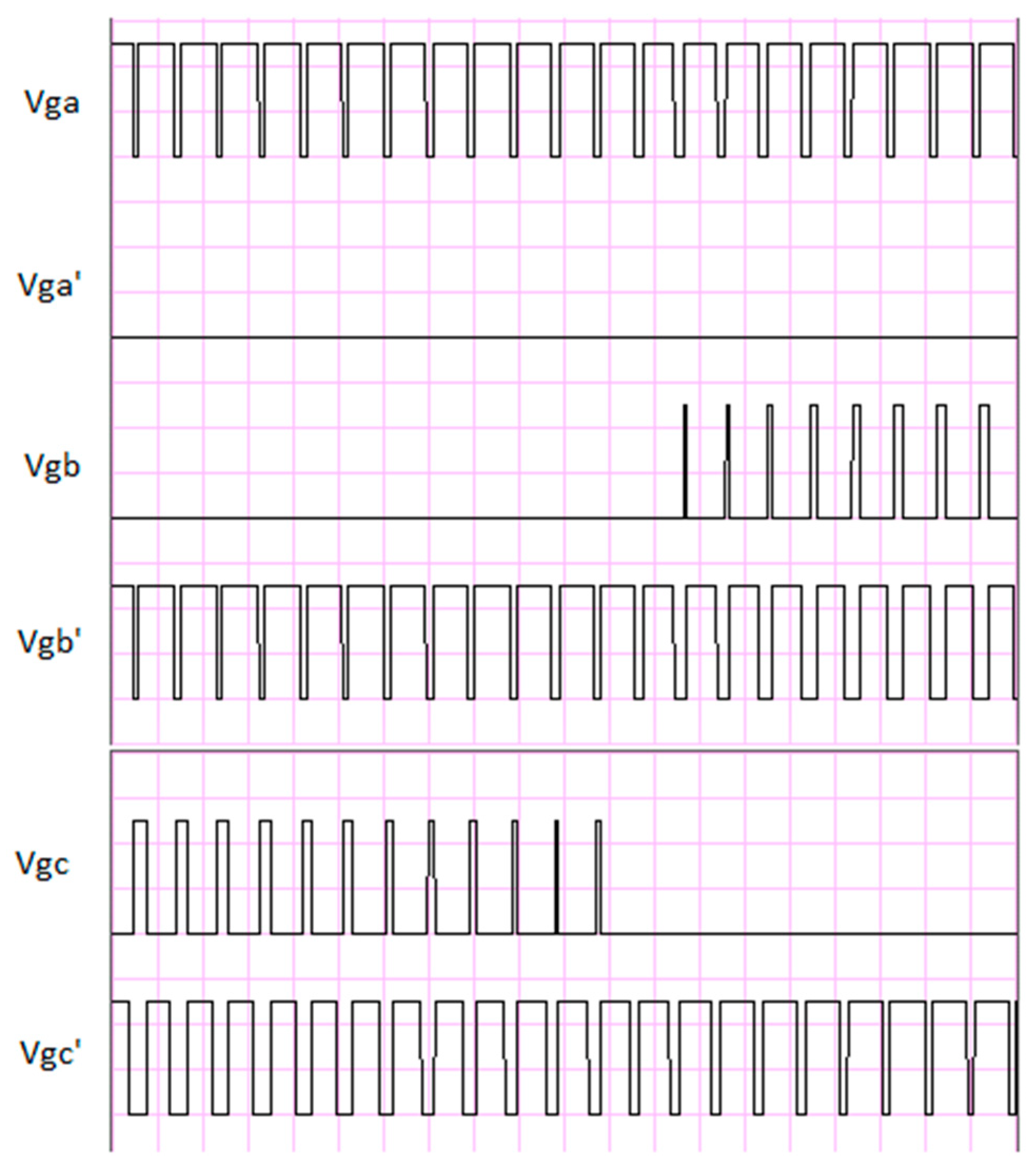
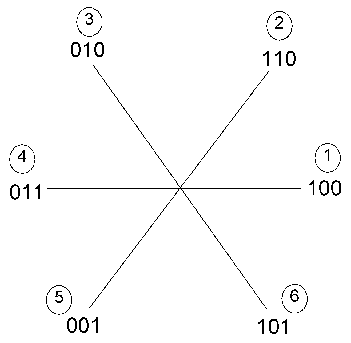
| Position | A’ | A | B’ | B | C’ | C | Hex Code |
|---|---|---|---|---|---|---|---|
| 1 | 0 | 1 | 1 | 0 | 1 | 0 | XX68 |
| 2 | 0 | 1 | 0 | 1 | 1 | 0 | XX58 |
| 3 | 1 | 0 | 0 | 1 | 1 | 0 | XX98 |
| 4 | 1 | 0 | 0 | 1 | 0 | 1 | XX94 |
| 5 | 1 | 0 | 1 | 0 | 0 | 1 | XXa4 |
| 6 | 0 | 1 | 1 | 0 | 0 | 1 | XX64 |
| Case-1 (Mode-1) | Case-2 (Mode-2&3) | Case-3 (Mode-1,2 & 3) | Case-4 (Mode-1&2) | |
|---|---|---|---|---|
| Average Battery Current | 3 A | 0.82 A | 1.48 Amp | 1.8 Amp |
| Ultracapacitor Current (Discharging) | 0 A | 2 A | 2 A | 1.6 A |
© 2019 by the authors. Licensee MDPI, Basel, Switzerland. This article is an open access article distributed under the terms and conditions of the Creative Commons Attribution (CC BY) license (http://creativecommons.org/licenses/by/4.0/).
Share and Cite
Mahadik, Y.; Vadirajacharya, K. Battery Life Enhancement in a Hybrid Electrical Energy Storage System Using a Multi-Source Inverter. World Electr. Veh. J. 2019, 10, 17. https://doi.org/10.3390/wevj10020017
Mahadik Y, Vadirajacharya K. Battery Life Enhancement in a Hybrid Electrical Energy Storage System Using a Multi-Source Inverter. World Electric Vehicle Journal. 2019; 10(2):17. https://doi.org/10.3390/wevj10020017
Chicago/Turabian StyleMahadik, Yogesh, and K. Vadirajacharya. 2019. "Battery Life Enhancement in a Hybrid Electrical Energy Storage System Using a Multi-Source Inverter" World Electric Vehicle Journal 10, no. 2: 17. https://doi.org/10.3390/wevj10020017
APA StyleMahadik, Y., & Vadirajacharya, K. (2019). Battery Life Enhancement in a Hybrid Electrical Energy Storage System Using a Multi-Source Inverter. World Electric Vehicle Journal, 10(2), 17. https://doi.org/10.3390/wevj10020017