Article

BIM Methodology in Structural Design: A Practical Case of Collaboration, Coordination, and Integration

by
Alcinia Zita Sampaio
1,
Paulo Sequeira
1,
Augusto M. Gomes
1 and
Alberto Sanchez-Lite
2,*
1
Department of Civil Engineering, Higher Technical Institute, University of Lisbon, Av. Rovisco Pais 1, 1049-001 Lisboa, Portugal
2
Department of Materials Science and Metallurgical Engineering, Graphic Expression in Engineering, Cartographic Engineering, Geodesy and Photogrammetry, Mechanical Engineering and Manufacturing Engineering, School of Industrial Engineering, Universidad de Valladolid, Paseo del Cauce 59, 47011 Valladolid, Spain
*
Author to whom correspondence should be addressed.
Buildings 2023, 13(1), 31; https://doi.org/10.3390/buildings13010031
Submission received: 29 November 2022 / Revised: 15 December 2022 / Accepted: 20 December 2022 / Published: 23 December 2022
(This article belongs to the Special Issue Smart and Digital Construction in AEC Industry)

Abstract

:
Building Information Modelling (BIM) is a methodology focused on the centralization and sharing of project information among all experts involved. The use of BIM platforms allows professionals to improve coordination, collaboration, and integration along with the development of all disciplines and tasks required in a complete building project. Currently, the construction industry has witnessed a growing adoption of BIM, mainly caused by the constant technologic achievements, contributing to the improvement of the integration capability of the available software. However, concerning structural design, BIM implementation still presents some difficulties, especially in the interoperability of BIM-based systems. In the present study, a structural design case was considered, using Revit as the modeling software and Robot as the structural system. A bidirectional exchange of information between the two systems was required and the interoperability capacity was evaluated. In the process, the main identified remarks concern the fundamental aspects of information sharing, collaboration, integration, and interoperability. Despite the limitations found, essentially related to the software interoperability, the BIM approach presents significant advantages in a structural project, supported by 3D visualization, model overlapping, easy accessibility to the model database, streamlined coordination, and enhanced collaboration.

1. Introduction

The construction industry has been adopting emerging technologies that have improved productivity in the sector, particularly in the development of projects. Currently, building design presents volume, complexity, and multidisciplinary integration, which by the traditional method based on drawing, becomes difficult to manage in time and in control of costs. The need to automate and optimize processes contributed to the appearance of the Building Information Modelling (BIM) methodology, a process focused on centralizing all project information in a virtual BIM model [1]. The BIM-based programs allow the creation of a reliable three-dimensional (3D) representation of the building, including the various specialties that make up a project, and supporting an improvement in the coordination and compatibility of phases. In recent decades, there has been a significant increase in the adoption of BIM methodology, from different areas of the construction sector, due, in part, to the improvement of the software technology, but also to the confirmation of its benefits when applied in real cases, as widely reported [2]. The workflow of the collaborative design in BIM includes not only architecture and structure design but also mechanical, electrical, and plumbing systems design and analysis. In this sense, BIM lets a real collaboration take into account all requirements of the project. Scientific literature shows successful practical cases of this collaboration [3,4]. However, in construction enterprises, changing from the traditional work method to the new methodology requires a high initial investment in training and software.
The most recent advances in BIM technology have been offering innovative opportunities to improve the efficiency and effectiveness of construction activity concerning buildings and infrastructures, enhancing traditional project management, and transforming the project delivery process [5]. In an integrated strategy, the data in a BIM model must be stored in an organized and structured way, where an adequate ontology must be conceived, linking data technologies for sharing data between software [6], and where cloud-based BIM modeling for collaborative multidisciplinary design can be applied [7]. However, some barriers have been found concerning essentially BIM-based construction networks, namely the geographic disperse of the members from various organizations [8], with an enterprise discontinuity [9] and a low level of communication between disciplines, such as architects and engineers [10].
Structural engineering comprises a wide range of skills and competencies applied in finding structural solutions, in order to give a guarantee of safety, sustainability, and durability of buildings, systems, and infrastructures [11]. A high level of collaboration can improve the quality of a multidiscipline BIM project. Concerning the structural project, including all data transfer steps that are required along the comprehensive process, the collaboration supported in BIM models brings benefits in the productivity, coordination, and visualization within an integrated project [12], as the models give a general overview of the architectural, engineering, and construction components. The structural design must be integrated with the outputs concerning disciplines, namely architecture and distinct engineer expertise. In addition, the construction engineer can control the supervising of the construction activities on-site and improve communication with manufacturers and suppliers [13].
Considering that BIM is relatively recent, enterprises are not yet fully prepared. BIM presents some coordination limitations, as well as the interoperability capabilities of the available software most used in a structural project. In this sense, the present study analyzes the technological advances that have been achieved, identifying appropriate strategies for performing different tasks associated with the design of structures. A real building case was worked out from the perspective of modeling a structural design, following the architectural alternative solutions, and proving adequate communication between both teams when supported in the BIM technology. In addition, the frequent problems related to inefficient interoperability that still exists in the transfer process that is required along the elaboration of a structural project are identified and strategies for resolution are presented. Finally, the main benefits in collaboration, coordination, and integration found during the development of the study were carried out, contributing to the dissemination of BIM applied in structural design [14].
The present study was developed within a master context. The architectural and structural drawings were made available by architectural and structural offices concerning the selected study case. Along with this work, several changes to the architecture design were made, as well as important replications of the structural solution, requiring constant updates. The objective of the master study was to demonstrate how BIM can support and improve the quality of a global project when at least two disciplines were involved in the process. The great capacity of BIM in integration, collaboration, and in the support of frequent updating of both projects are well illustrated in the study.

2. Building Information Modeling (BIM)

Eastman [15] first mentioned the fundamental concept of BIM methodology, referring to a hierarchical system of building components in the composition of a digital model, in 1975, using the designation Building Description System (BDS). The author described a system that allows the creation of elements associated with shape, location, and property information. Later, in 2009, as referred by Succar [16], the designation Building Information Modelling (BIM) was adopted for this new approach concerning design representation. The elaboration of a building project, involving all disciplines and the required associated task, using the available BIM software, is provided in the form of a digital parametric model, containing the geometric details necessary for its realistic visualization. It also incorporates several types of mechanical properties, such as density or modulus of elasticity of the applied materials. The BIM model offers a complete, updated, and accessible database, allowing data sharing between partners and phases, encompassing all stages of the life cycle of a building [17,18].
Compared to Computer-Aided Design (CAD) software, the use of BIM systems decreases the possibility of errors and omissions in the design process, which often lead to delays, additional costs, and even potential lawsuits between the various parts of a design team. One of the most common problems associated with the use of CAD systems is the time and cost required to generate critical evaluation information about a project proposal, including cost estimates, energy consumption analysis, or structural concrete reinforcement details [19]. The BIM contribution in the study of alternative proposals corresponds with supporting the professionals of the design team in easily performing the eventual adjustments of the model being created based on a sustained 3D visualization and consultant of the model database, along with the creation process. The final design, following the required specifications and adjustments according to the endorsed modifications in a collaborative and integrated way, constitutes obtaining a high-quality product [19]. The improved capability, evident in teamwork, coordination, and collaboration, leads to the improved performance of professionals and reduced costs associated with the project design, providing benefits to all experts involved [20].
The transition from a traditional process, rooted in technical drawings, to the BIM approach requires procedural changes and a significant investment in technology and training. In the context of the enterprise, the implementation of BIM requires the restructuring of its internal functional processesF as part of a strategy to adapt traditional working methods to the new paradigm, as well as a change in inter-company communication [20]. The internal reorganization of enterprises and the change in collaboration practices between partners in a project present some limitations, mainly due to the lack of assimilation of the capabilities of its applicability and efficiency. In some activities, professionals still do not recognize the advantages and technological potential of using an integrated BIM platform in the development of their activity [19].
Currently, the resistance to its implementation is changing towards moderate acceptance by all professionals in the various areas covered by the industry. Companies have been recognizing that this transition is inevitable and its implementation in work practices should be understood as a mandatory requirement [21]. In all areas of the construction industry, owners, designers, builders, and managers have been reporting the benefits of adopting the BIM methodology in their specific activities. This has contributed to the rapid and growing acceptance of BIM, leading government entities to establish guides and deadlines for mandatory implementation in public buildings [22]. Despite the relative benefits of implementing BIM in the industry, its adoption in enterprises and project offices has imposed significant organizational challenges related to internal cultural adaptation regarding ways of working, data transfer processes, and communication with partners [23,24]. These problems have resulted in a consensus on the need for the BIM approach to be supported by interoperability between software [25]. Currently, interoperability between software points to two main approaches [26,27]:
  • The open and standardized data format was designed as Industry Foundation Classes (IFC) [28,29] and created by the international organization BuildingSMART [30].
  • The transfer made through the native data format, related to the use of extensions, add-ins, and plug-ins, made available in the modeling systems which ensure the reading and manipulation of models, transferred to those specific applications.
Despite the constant effort in research carried out in academic and business environments, the technology market still does not provide a completely effective solution to the persistent limitation of interoperability in some of the tasks that require a model transfer in the pursuit of the development of different stages of the project, negatively affecting its implementation [31]. This makes interoperability the main practical barrier to successful BIM adoption in the industry [32].

3. Materials and Methods
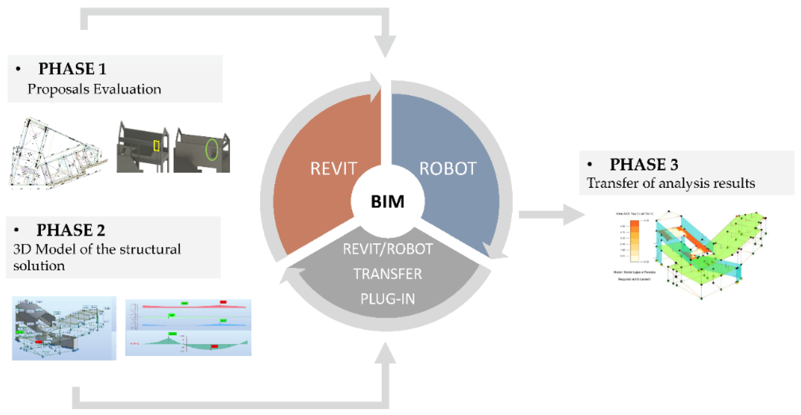
The case study chosen to develop the structural concrete reinforced design in the BIM environment is a single-family house, located in the archipelago of Azores, Portugal, on the island of Faial [12]. The house has two bedrooms with 258.3 m2 of gross floor area and 182.2 m2 of building area. The process of creating the architectural design admitted several alternative options, providing, in the context of this study, an illustration of how the BIM model serves as an adequate work basis and understanding of the coordination between the activities of the architect and the structural engineer. The preliminary drawings were provided by the engineering office involved in the design, and are composed of plans and elevations of the architectural project and of a preliminary structural solution.
The applied methodology consists of three phases (Figure 1). Starting from the study of the proposals (phase 1), they were modeled in 3D using Revit software. The structural analysis was performed using Robot software (phase 2). The Revit model was transferred to Robot software using the plug-in Revit–Robot. The interoperability capability between Revit–Robot and BIM benefits in collaboration, coordination, and integration were studied in phase 3. Interoperability under construction can be defined at different levels and approaches [33]. Semantic interoperability is related to the meaning and mode of the data exchange. Different authors have studied the interoperability of Computer Aided Design (CAD)—Computer Aided Engineering (CAE) software from a structural engineering and design point of view [34,35,36,37,38]. These studies describe different ways of exchanging data: via a direct link using a native file or an API, or an indirect link through a third-party channel. The first mode requires the use of the same software provider, or two software providers connected via an application programming interface API. The second also requires additional software. As Zhou et al. describe, Revit has great potential through its application programming interface (API) to integrate applications into the Revit platform [39]. In this sense, Revit can work with programs such as ANSYS [39], hybrid BEM-FEM programs [40], ETABS, or SAFE [41]. Revit can collaborate with the Robot CAE program using a direct link by a specific plug-in, with other structural CAE programs such as RSA, Tekla Structures, Modest, RFEM, SAP2000, or Edilus, using the Industry Foundation Classes (IFC) format. A number of published studies show results that are not completely satisfactory from the point of view of operability with the use of the IFC format.

4. Case Study

This section describes the results obtained following the methodology described in Section 3 and Figure 1.

4.1. Phase 1: Proposals Evaluation

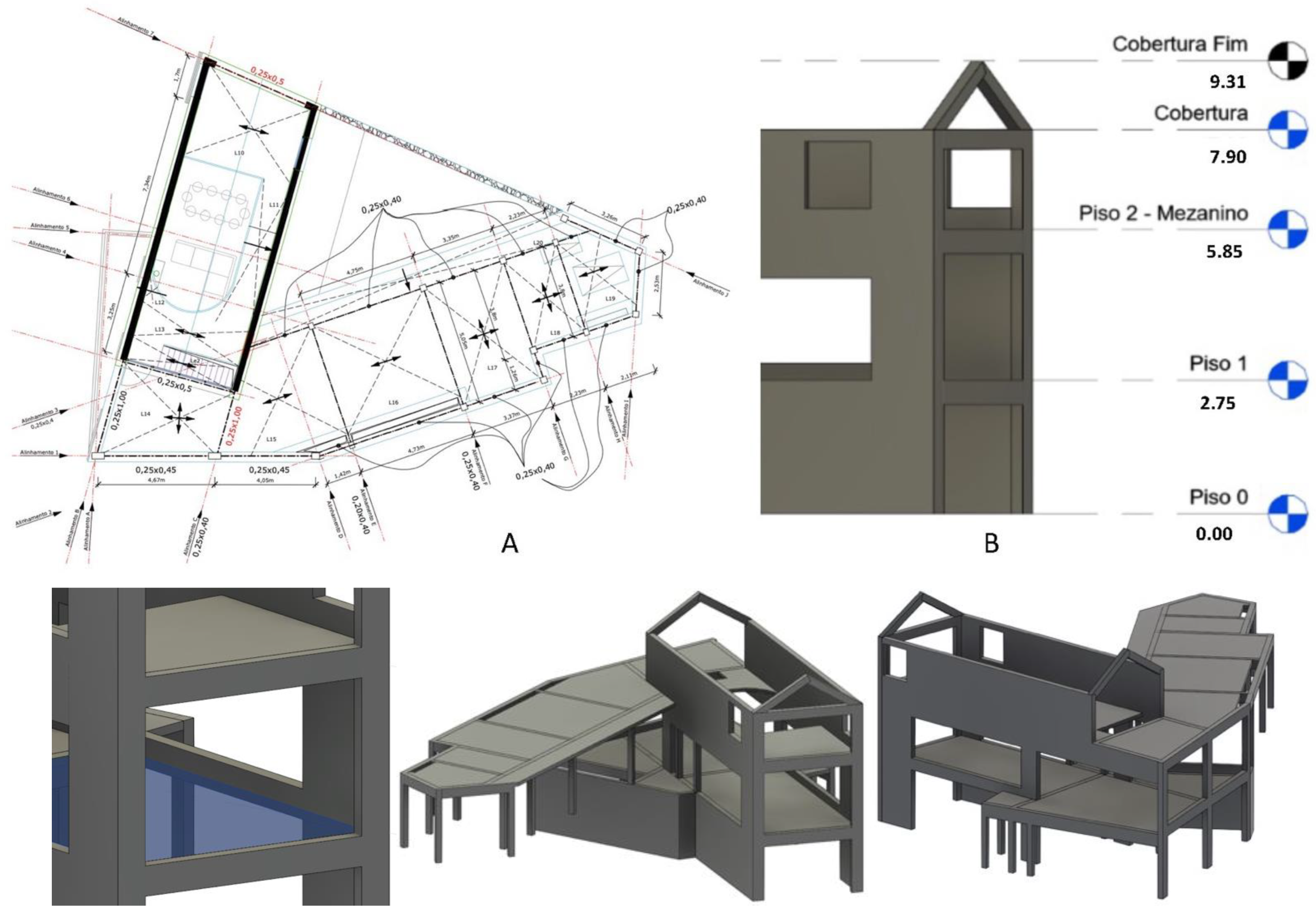
4.1.1. Pre-Dimensioning Proposal

The proposed structural solution consists essentially of a reinforced concrete beam structure, formed by columns, beams, walls, and slabs, and a complementary mixed structural system, formed by frames and walls.
The BIM model generated and presented in Figure 2 shows: At level 0, the adopted structural walls of 0.20 m and 0.25 m thickness. On floors 1 and 2, the solid slabs are 0.17 m thick, supported by a beamed system. The structural walls conceived for floor 2 correspond to the structural solution found to meet the architectural constraints. However, for the seismic action, these elements are not recommended because they introduce more mass in the upper floor and, consequently, increase the horizontal forces. A sloped roof was defined in a reinforced concrete slab on the main body, and an accessible terrace roof on the secondary body, and both slabs are 0.15 m thick.
The conceived structural solution was the result of a series of adjustments made to the initial pre-dimensioning proposal, following the architectural changes that were made to the initial architectural solution (Figure 2). The model was created based on the drawings of the architectural design that were imported to the Revit software.

4.1.2. Study of Alternative Solutions

The project under analysis was submitted with changes made to the architecture design, while the structural model was being developed, compelling a series of adjustments over the structural solution. The most relevant project changes were analyzed, and the BIM models of the structures were adjusted according to the imposed modifications. The architect proposed some changes to the project, which in several situations led to problems that were difficult for the engineering office to solve (Figure 3):
  • The first change considered in the model of structures was requested by the office responsible for the architecture for having reformulated the size of the garage. It was necessary to remove a beam on the 1st floor, as it conditioned the installation of the garage door.
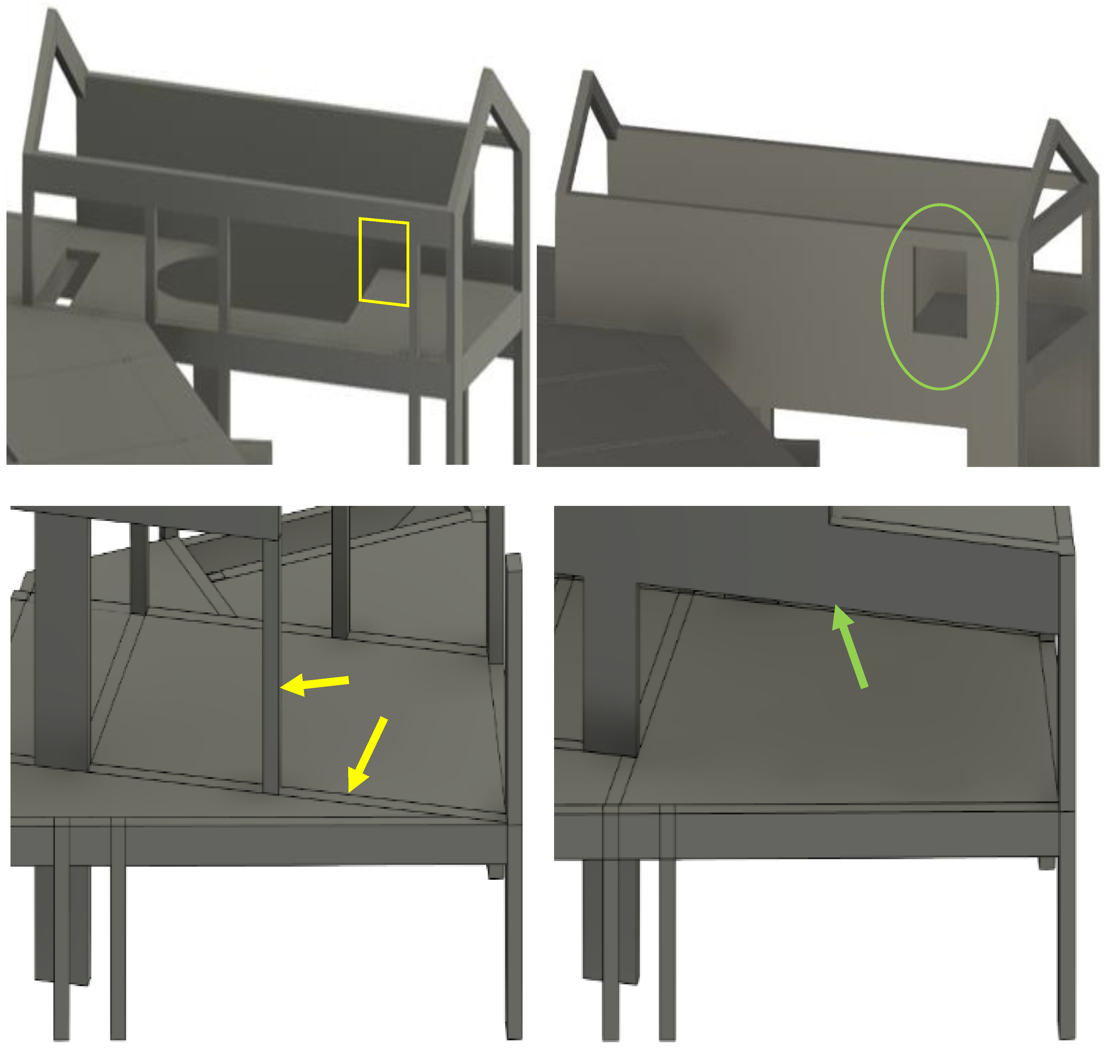
  • The 2nd amendment required the placement of the window shown in Figure 3, which made it impossible to place a beam with the required dimensions.
  • The 3rd modification required by the architectural office consisted of the removal of two columns on the 0th floor, creating a continuous span in almost the entire front of the building’s main body.
These difficulties were often not visually understood by the architectural office when the dialog was supported in drawings, which led to a significant increase in the cost of the building structure, which could have been minimized with minor adjustments to the architectural design. The use of the BIM model to assist in the 3D visualization of the project improved the communication between both offices. However, several meetings were conducted based on the architectural drawings and the BIM structural model.
The engineering office benefited significantly from the use of BIM in this project, as it was easy and fast to make changes to the structure and perform the respective structural analysis at any stage of the design. If the architecture model had been executed in BIM, the communication would have been more easily established, leading naturally to a better understanding on both sides of the constraints, requirements, and possibilities of resolution in a collaborative mode.

4.2. Phase 2: 3D Model of the Structural Solution

The physical and analytical models of the structure were created and visualized using the Revit software. Before modeling, it was important to set up the basic parameters of the structure model to be generated, such as the design units and materials to be applied. After, the modeling process began with the definition of the project alignments and levels. In it, the imported CAD drawings served as the basis for the placement of the structural elements. Then, the first elements, which were columns, beams, walls, and slabs, were modeled. The foundations were modeled after the definition of the columns and the retaining walls.

4.2.1. Geometric and Analytical Models

The modeling process using Revit is very intuitive, supported by the interactive interfaces of the different families of elements available in the system. The user selects an element from the required family of objects and adjusts its dimension to the cross-section or thickness as designed. The modeling of some elements, such as corner columns, inverted beams, non-regular slabs, and sloped roofs, revealed some complexity and limitations, mainly regarding the compatibility of geometric and analytical models (Figure 4).
In Revit, the geometric model can be represented in its analytical configuration. It is automatically generated by the software. An analysis of eventual geometric inconsistencies was then performed. Some errors were detected when the geometric limits of elements did not coincide with the analytical limits.
To support the analyses, adequate functionalities available in Revit can be applied to support the detection of errors in the analytical model. In the present practical case, the visual filter functionality was used to detect unconnected nodes. The filter allows the user to highlight disconnected nodes by changing their color, alerting the user to quickly localize the missed situation (Figure 4). Adjustments were also made to the analytical slabs, allowing for a correct visualization of the different analytical elements (Figure 5).

4.2.2. Structural Analysis and Design

Once the structural model was completed and the consistency of the analytical model was checked, the model was transferred to the structural calculation system, Robot, in order to perform the structural analysis. The Revit/Robot data transfer of the structural BIM model between the two BIM-based systems was carried out by using the Revit/Robot plug-in through the direct integration option, allowing a fast two-way transfer of information (Figure 6).
In order to understand whether the calculation model behaves as expected, a first calculation of the structure was made considering only its own weight. The absence of the remaining loads did not influence the creation of finite element meshes by the software. After the calculation, some inconsistencies, identified as rigid links, were found. In it, the software created rigid links between nodes that did not intersect correctly and in areas where finite element meshes were not coherent. No errors were detected when performing the transfer, although some flaws were identified later in the analytical model, as some slab nodes were poorly connected in Revit (Figure 6). Once the model was checked for consistency, the loads and load combinations were defined and applied.
  • The loads considered as dead loads were the self-weight, which is automatically defined and applied by the calculation program, plus the remaining loads, such as partition walls and floor coverings. The applied live loads were defined according to the Portuguese norm, NP EN 1991-1-1, classifying the case study in category A with the type of use “Domestic and residential activities”.
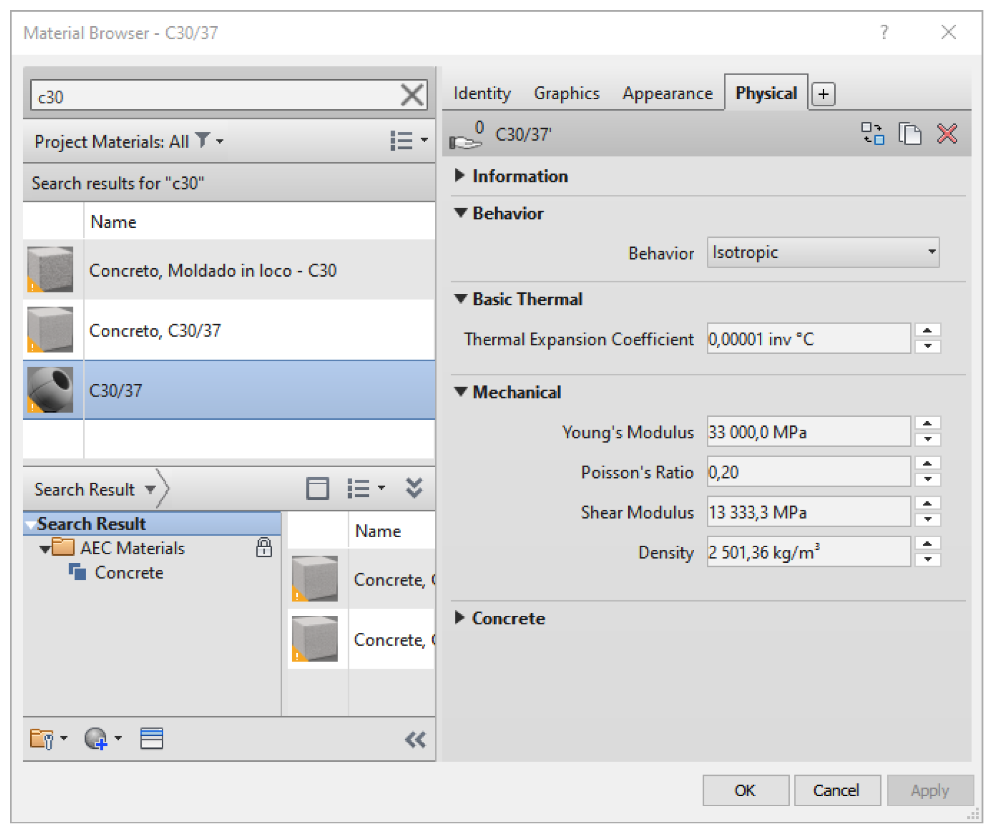
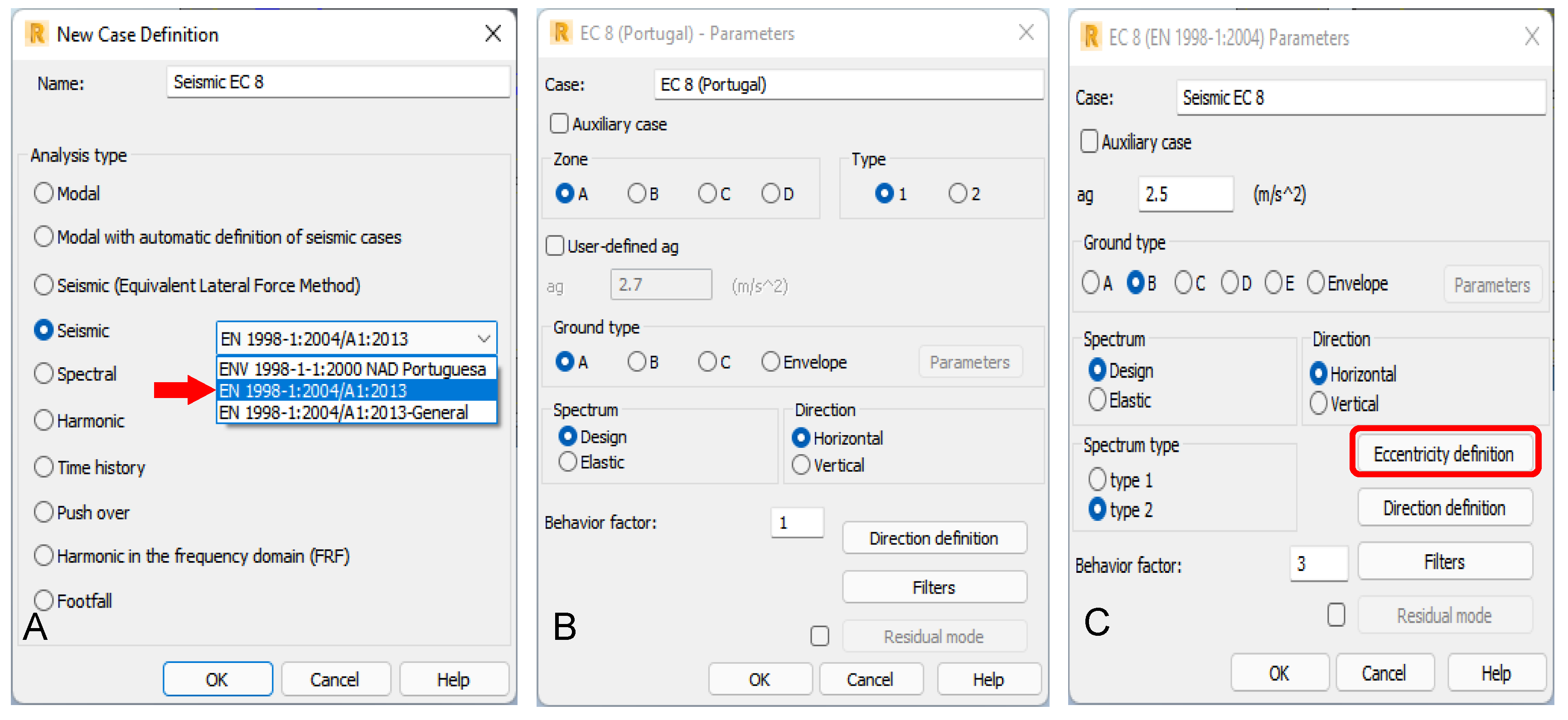
  • The concrete properties, namely shear modulus or poison ratio, were adjusted to the selected material, C30/37 (Figure 7). The soil acceleration value (ag) of 2.5 m/s2 for the predominant type of earthquake in the Azores (type 2 earthquake) was obtained by the Portuguese Standard NP EN 1998-1 of 2010 (Figure 8). The load values considered are listed in Table 1 and Table 2.
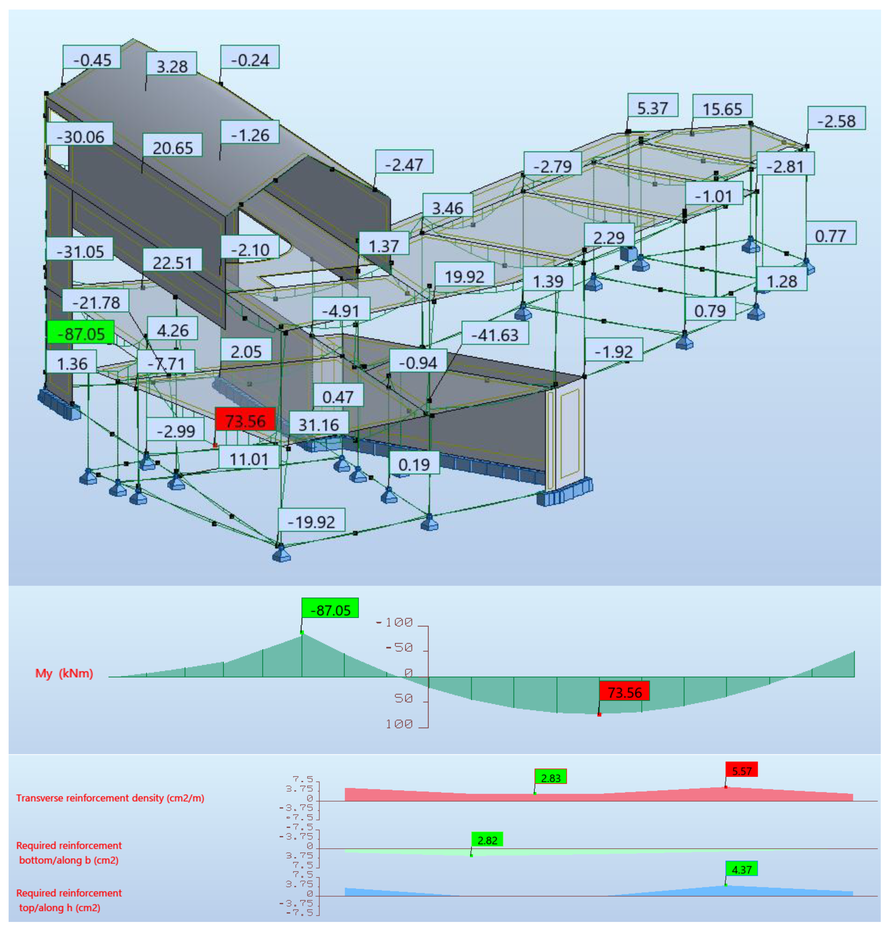
  • After the definition of dead and live loads, the seismic action was considered through a modal analysis by response spectrum since the building has an irregular geometry and it is located in a high seismicity zone. Then, the structural analysis was performed (Figure 9).
  • The analysis results were obtained using Robot. Robot allows for a complete structural analysis of the building structure, providing diagrams of efforts, reactions, deformations, and effort maps, among other options. The information can be presented graphically or in tables. The visualization of the results can be global or more detailed, allowing for the analysis of the elements individually. It is also possible to present the results of each load case separately, or to display the envelope forces according to the defined combinations, making it easier to identify critical points. These results can be transferred to Revit and consulted.
  • The reinforcement detailing is rigorous, although some problems and limitations were detected (Figure 10):
    -
    In foundation design, it is not possible to create combined footings with more than two columns;
    -
    The eccentricity applied in Revit is not considered by Robot and consequently, the calculation of the suspension reinforcement is not correct;
    -
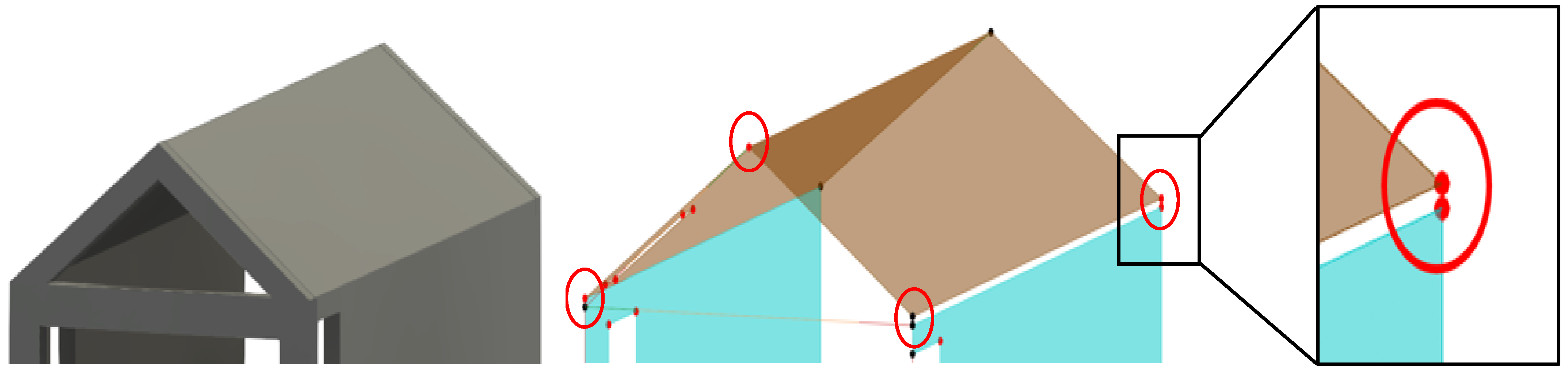
    In the detailing of the inclined roof beams, the reinforcement automatically generated by the program did not verify all the Eurocode conditions, and manual adjustments had to be made;
    -
    Although slab reinforcement can be dimensioned in Robot, it cannot be transferred to Revit;
    -
    The reinforcement design of structural walls has not yet been implemented in Robot according to Eurocode.

4.2.3. Reinforcement Detailing

Once the structural analysis was complete, the reinforcement detailing for each structural component was calculated. Based on the results of the efforts and behavior of the structure, the Robot software automatically calculated the necessary reinforcement, satisfying the requirements established in the related Eurocode. Subsequently, it generated the corresponding technical drawings of reinforcement detailing. The calculation of the reinforcement of the elements, except for the reinforcement of slabs and walls, was conducted through the provided reinforcement plug-in.
-
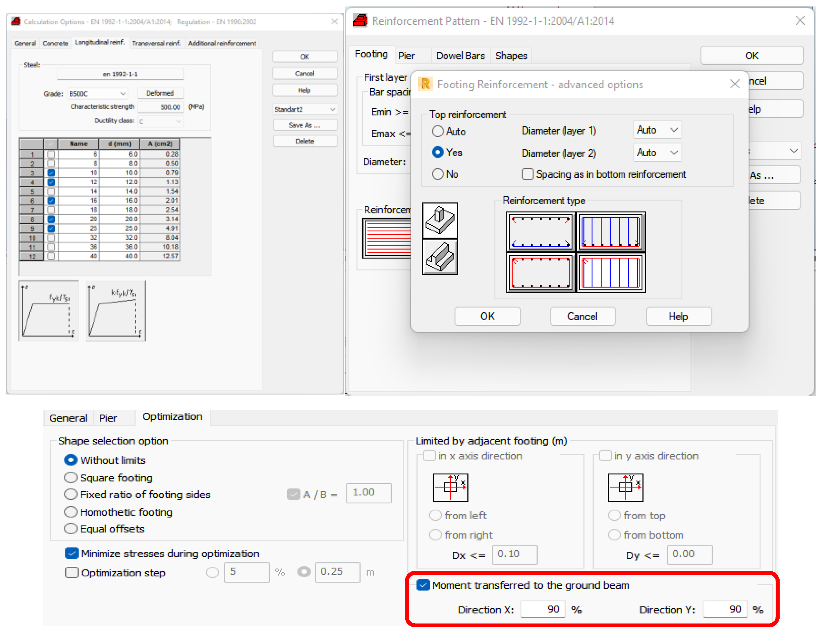
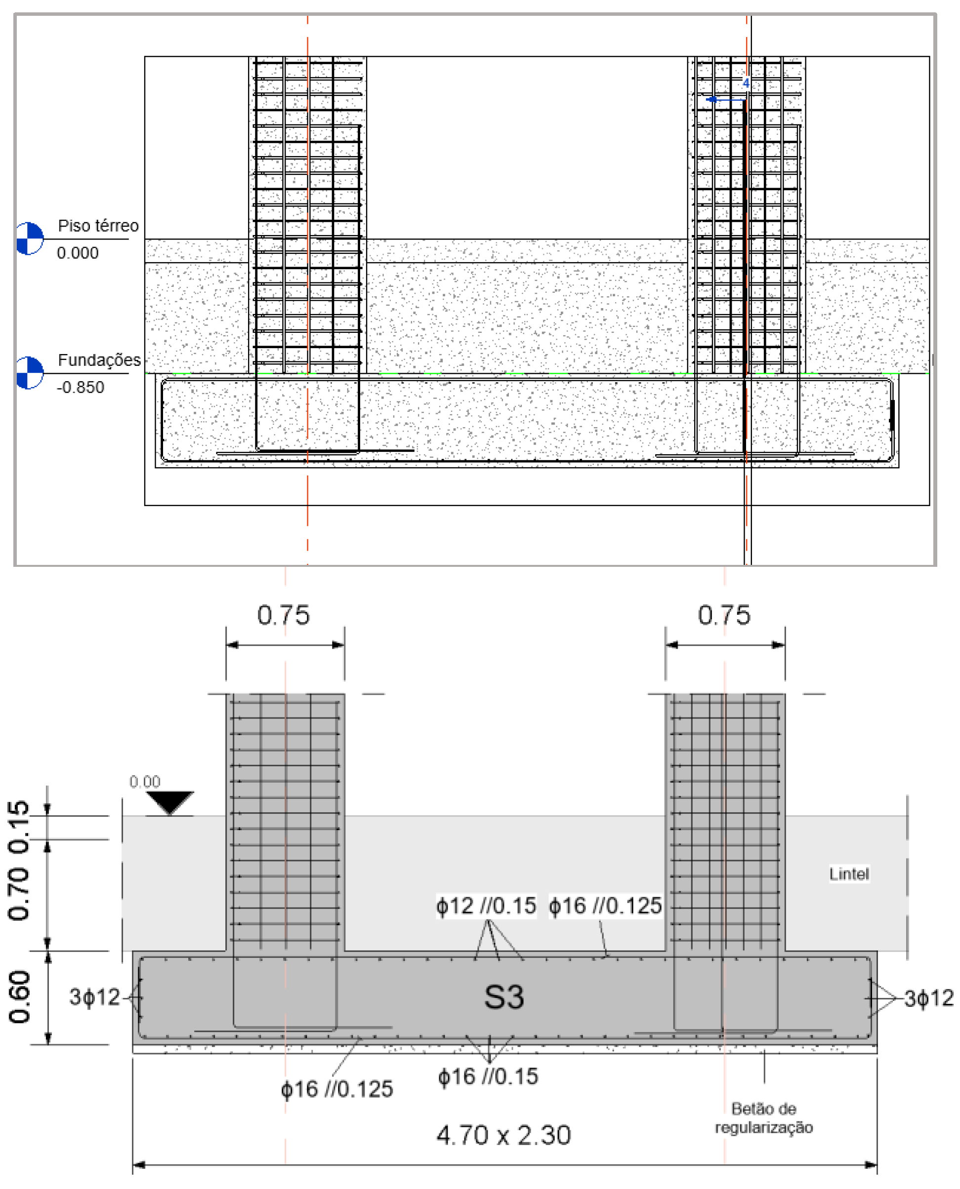
The concrete used in the foundations is of class C25/30. The diameters of the rods were restricted to diameters with a current use in Portugal and some aspects such as the type of distribution and the mooring angles were defined. For the correct dimensioning and validation of the detailing of the reinforcements, two distinct foundations were considered, isolated and continuous (Figure 11).
-
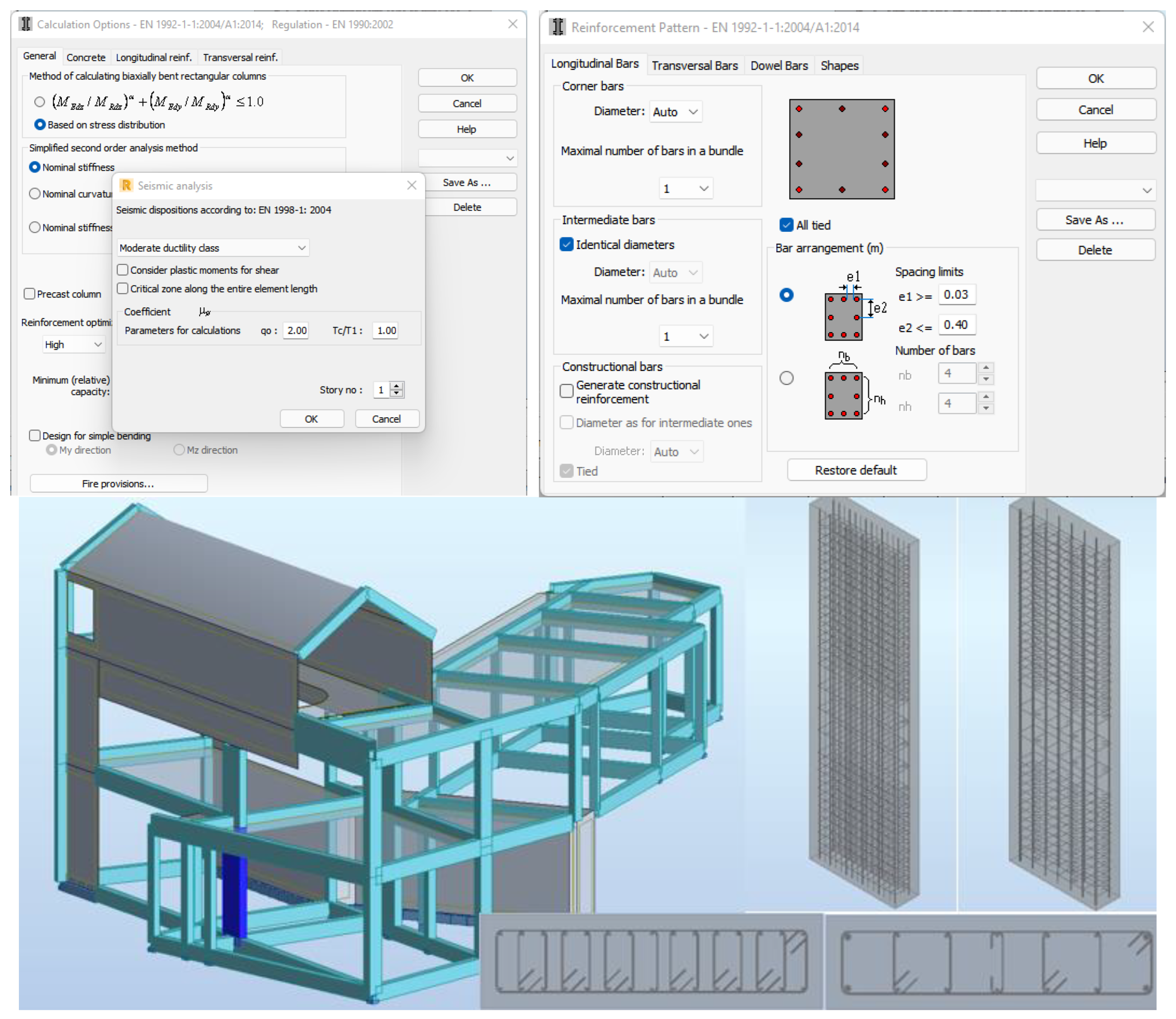
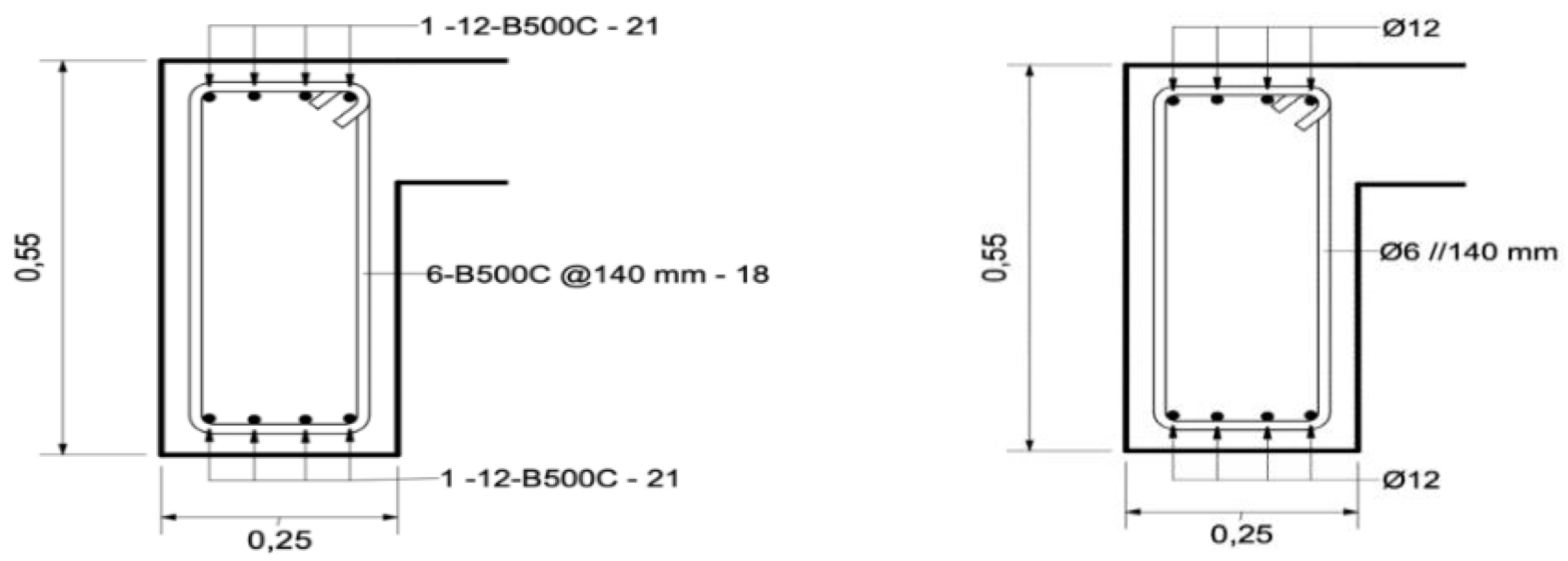
Concerning the columns, only some control parameters were defined prior to the calculation of the reinforcements, namely the maximum and minimum spacing and aspects related to the seismic arrangement of reinforcement according to Eurocode 8 (Figure 12).
-
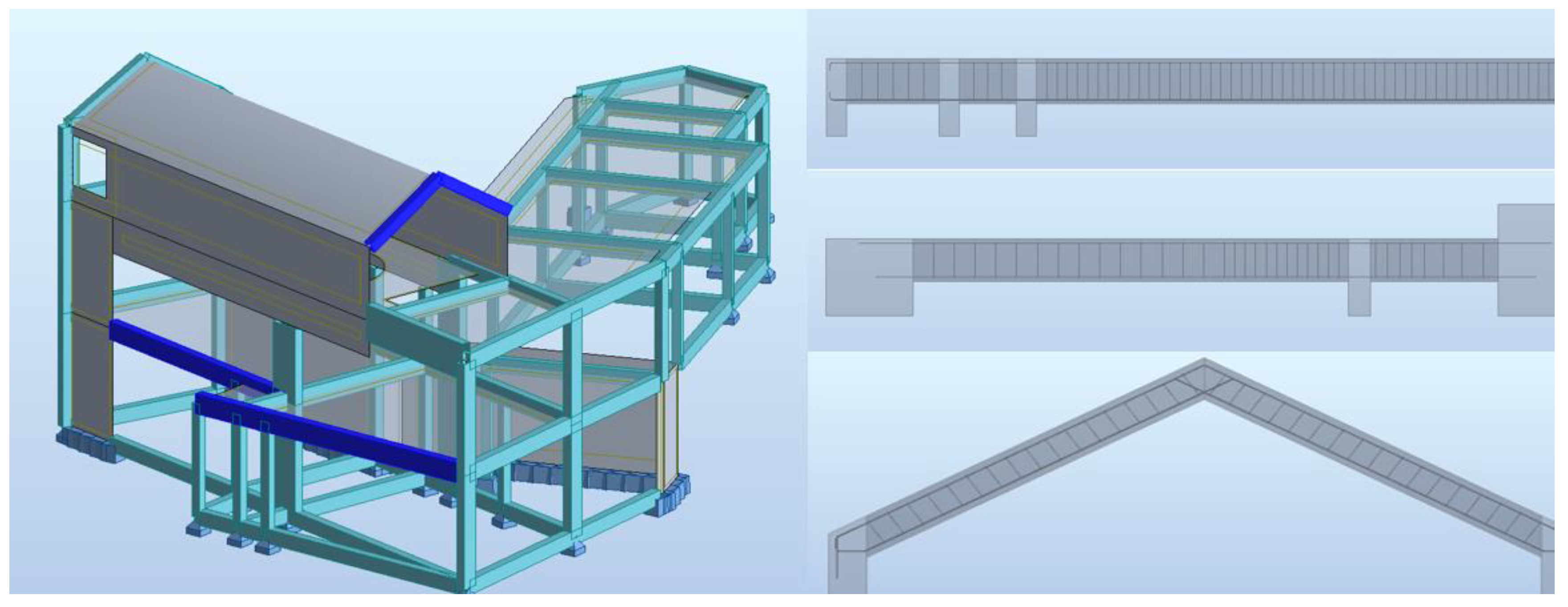
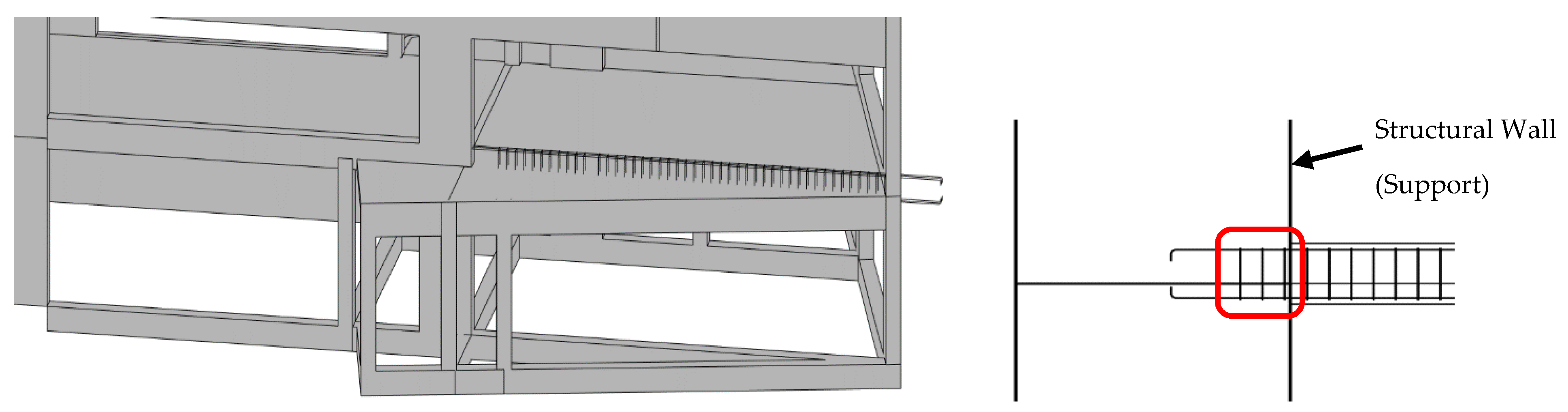
Concerning the beams, the parameters adjusted were related to the permissible deformed and the anchorage lengths (Figure 13). Regarding the continuous beam composed of an extensive span and two shorts, for the main, upper, and lower longitudinal reinforcements, three Ø12 rods were assigned with a reinforcement of a Ø12 rod in the areas in the middle of the span and on the supports. The stirrups chosen were of the double type, Ø6//0.20. In the sizing of the inverted one span beam, Robot initially did not recognise the wall on the left side as support, although the calculated efforts were not zero at this extreme, and an adjustment was then performed accordingly. In relation to the roof sloped beams, the software assigned the necessary reinforcements, but presented some errors in the reinforcement detailing that were adjusted.
-
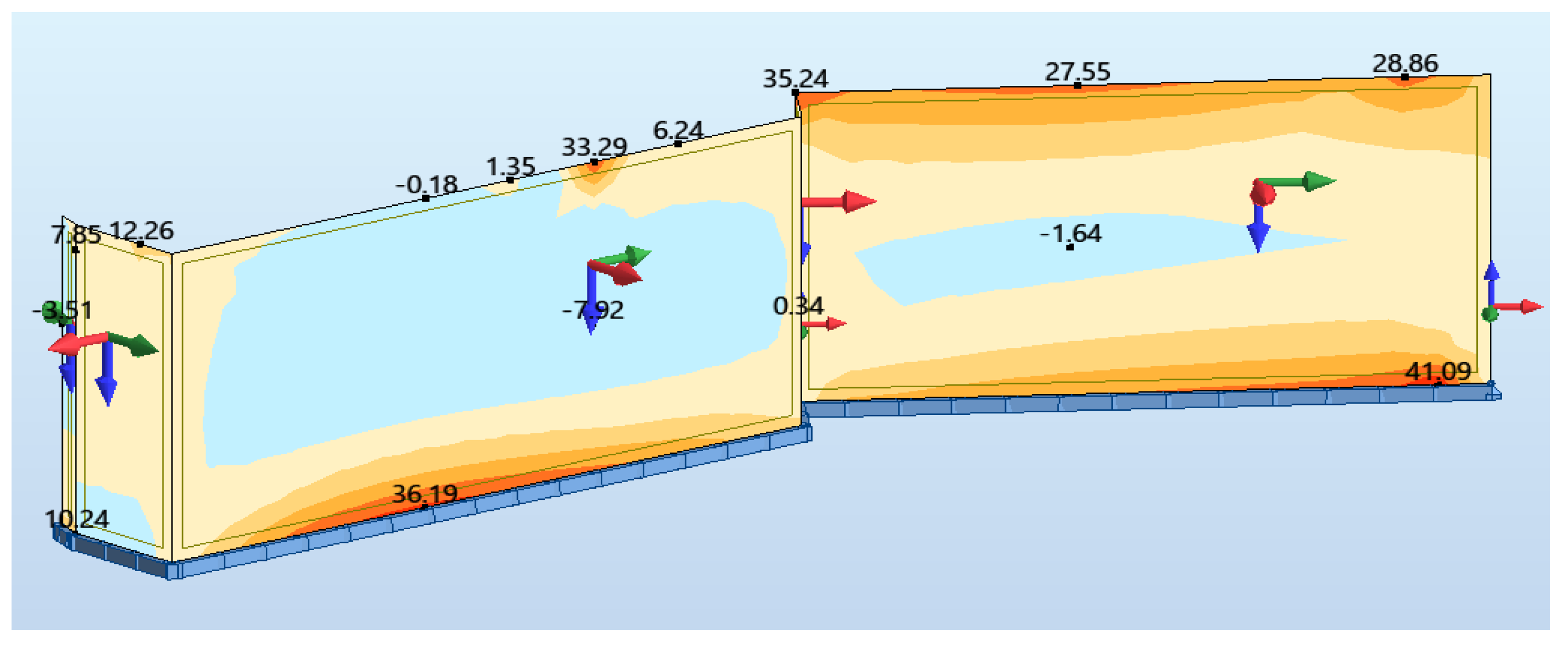
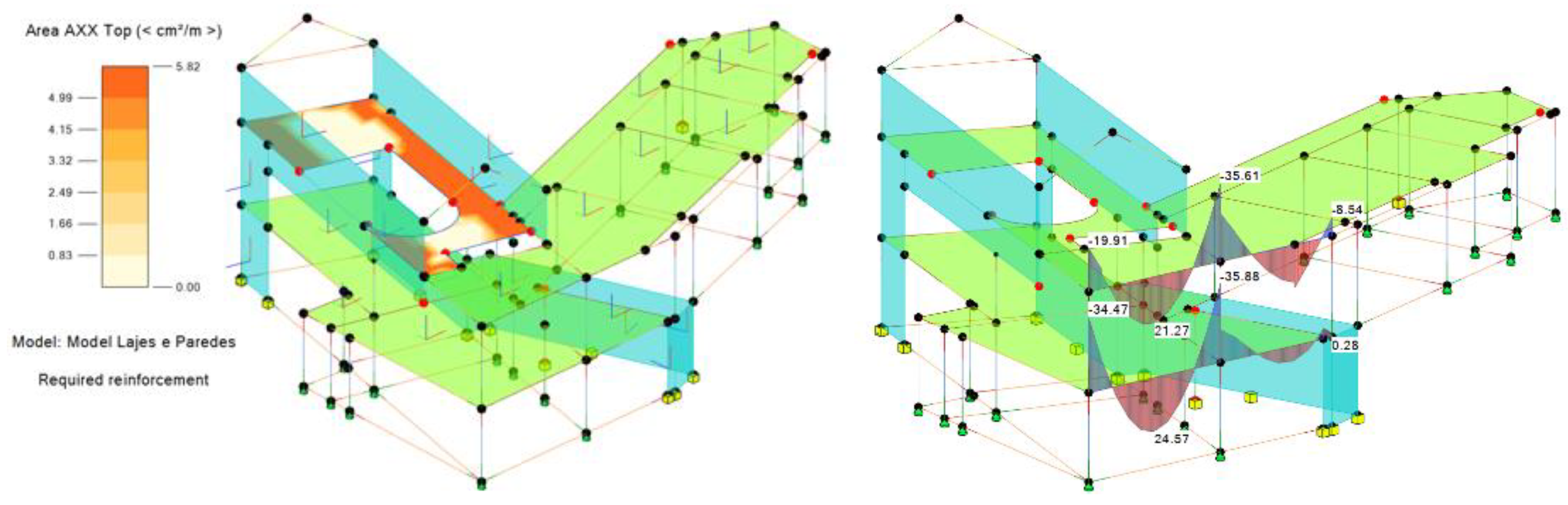
Currently, between Robot and Revit, it is not possible to transfer the reinforcements of the slabs. However, Robot has the capabilities to calculate adequately the bars distribution as well the technical drawings of the reinforcements detailing. In relation to the retaining walls, their design has not yet been considered in Robot, as required in Eurocode 8, but it allows the user to obtain the necessary values (Figure 14) to perform the correct reinforcement detailing.

4.3. Phase 3: Transfer of Analysis Results

The analysis of the interoperability capability between Revit and Robot (2022 versions) regarding the reverse transfer process, Robot/Revit, where there is usually a greater limitation, is evaluated in this item. On each type of element, the identified inconsistencies were analyzed and a possible resolution strategy was presented in order to overcome the difficulties found. The lack of interoperability demonstrated between the softwares led to the option of replicating some procedures, to “unite” the two models again. A general update was then performed on the Revit model, where most of the elements had to be adjusted, and then the Revit/Robot transfer was performed for the structural calculation. Afterward, the update operation of the Revit model was performed again, and, in the transfer process, there were no longer any warnings regarding significantly different models:
  • The foundation reinforcement transfer from Robot to Revit is only performed if its geometry is previously defined in Revit. Although the transfer is performed, in some situations the reinforcement has a skewed orientation in relation to the footings. This type of error, although easy to adjust, forces the user to spend some time on the correct representation of the reinforcement detailing in the foundation elements.
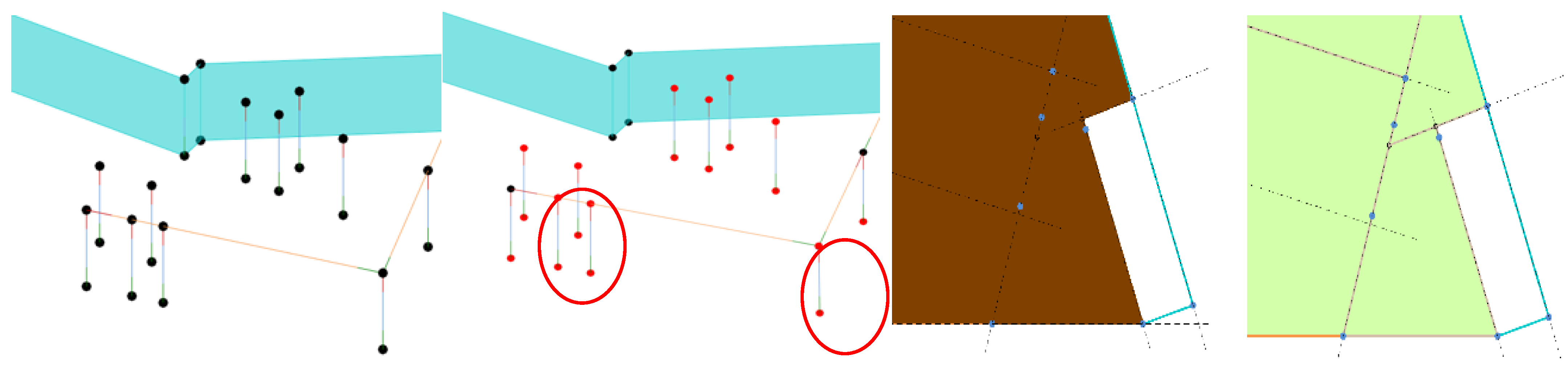
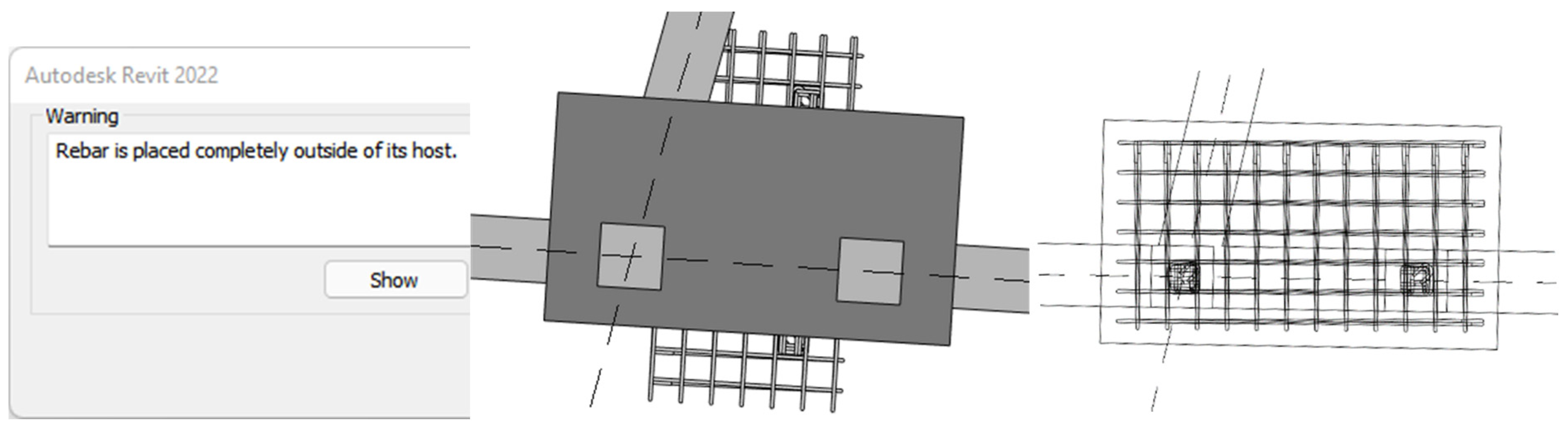
  • After that, the reinforcement transfer improved; however, some elements were not transferred correctly. When analyzing the transfer of the columns, no problems were identified. However, the software showed some difficulties in locating the geometry position of the beams and their orientation. Additionally, after the necessary adjustment of the reinforcement, it was verified in some cases that there were more stirrups than those that were necessary for the length of the spans (Figure 15). This happened because as Robot does not consider eccentricities, the software considered larger spans than those defined in Revit.
  • In the Robot/Revit transfer of the reinforcement of the columns and beams, an obstacle kept appearing which made it impossible to transfer the information quickly. When attempting to update these elements in Revit, the software reported that the Revit model was significantly different from the Robot model (Figure 10). When proceeding with the update, the elements were easily deleted from the model.

4.3.1. Transfer of Results

The direct integration between Revit and Robot allows for the transfer of the structural analysis results to the Revit model. This capability is especially useful when choosing and modeling slab reinforcement in Revit, where the required reinforcement area in each panel is quickly extracted (Figure 16). Additionally, it is possible to transfer the resulting stresses, displacements, and strains in columns and beams, concerning each loads combination.
Despite this integration, demonstrating the ability to centralize the results of the structural analysis in Revit, this process still has several errors. There were some difficulties in trying to transfer the results. The only solution found was to perform the update of the model, in a selective way by elements, beams and columns, and by groups of elements, such as slabs and walls. This procedure led to a better results transfer.
  • The transfer of the foundation elements from Robot to Revit continues to present a limitation as these elements are not recognized in Robot. In Robot, these elements were modeled and armed. To avoid this type of error, in Revit, the geometry of the foundations were exactly defined as remodeled in Robot, and after, the reinforcements obtained in Robot were almost correctly transferred to Revit. However, it was identified that the transfer of bars to some isolated foundations presented a skewed orientation in relation to the initial Revit foundations, and as such adjustments were performed (Figure 17).
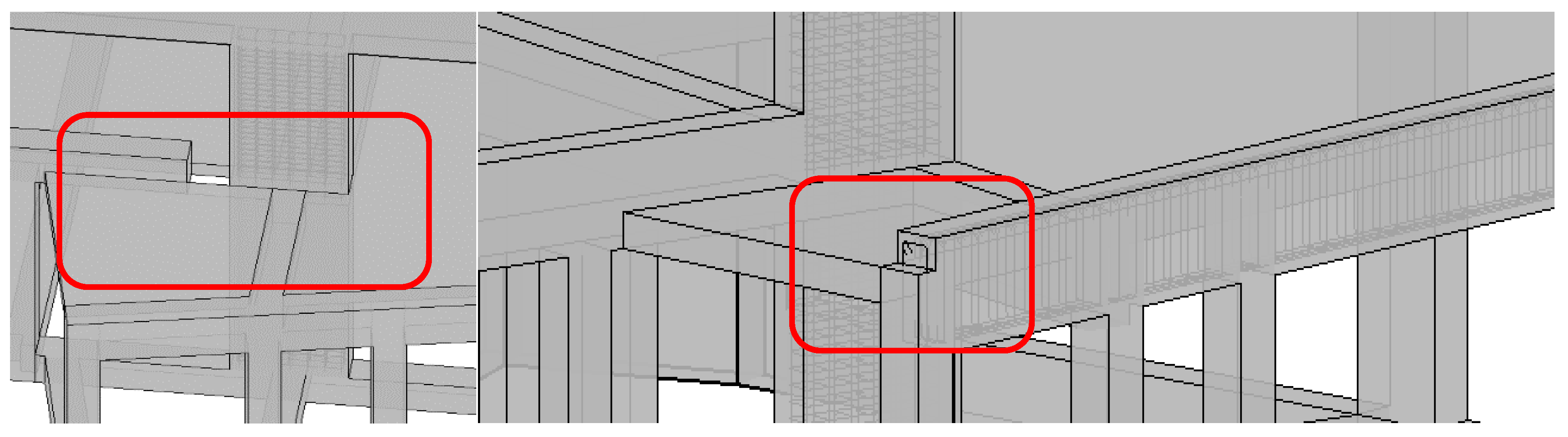
  • In the Robot/Revit transfer of the columns and beams reinforcements, an obstacle constantly arose when updating the initial Revit model. Using the ‘Update model’ option of Revit, the software informs the user that the first model is significantly different from the transferred Robot model. The ability to update the elements was excluded, and alternatively the reinforcements were sent from Robot to Revit, using the ‘Send model’ Robot functionality. Consequently, when the elements were sent and not updated, the previously defined eccentricities were lost, because they were not previously considered in the Revit/Robot transfer. This problem was identified in columns and beams (Figure 18).

4.3.2. Generation of Technical Drawings

Revit provides several options for programming how information is displayed by changing or creating families, allowing for adjustments to aspects related to text, color, thickness, etc. It also allows for more advanced capabilities through programming in Dynamo, a graphical programming platform directly accessible through Revit. However, these features require a high level of user experience.
Analyzing the current state of the Revit software, the ease in creating plans, elevations, and sections is noteworthy compared to traditional methods, but in the detailing of drawn parts, for the nomenclatures to be as desired by the user, time must be spent. In order to analyze the automation of Revit in aid of the creation of drawn parts, some technical drawings were created using only the annotations predefined by the software. Then, by modifying the family of annotations, Tags, a representation closer to the desired one was obtained (Figure 19). However, the figure still showed errors associated with longitudinal rods, Ø12, where the label to be placed should have been 4Ø12.
Within a design office, this work should be developed because the routines and the automation programs to support graphic representation are reusable and adaptable to each project.
In the present study, some drawings of structure designs were made. Although the process of modeling the structure was relatively simple, the drawings, which effectively correspond to planes extracted from the model, were too basic without all the traditional annotations. The great advantage over CAD drawings is due to the quick generation of all cuts, plants, and details without inconsistencies between them. However, the development of a design, from the application of a cut to the required technical design, requires some work and mastery of the systems’ support functionalities use.
Revit’s drawing tools allow the user to insert all necessary labels, comments, and captions into cuts, plans, and details applied over the BIM model. Additionally, all of these drawings are dynamic, which means that when changes are applied over the BIM model, all drawings become automatically updated. Thus, the usual and frequent work of correcting all drawings and verifying their implication over the other drawings is almost null in a BIM project. As an example, over a drawing of foundations, the dimension lines and labels applied over the structural elements and the reinforcement bars must be included and some adjustments must be made concerning the annotation lines and text (Figure 20).

5. Discussion and Conclusions

The present study analyzes the procedures required for the elaboration of a structural design using BIM software. In Revit, the analytical model is very dependent on the geometric model, which limits the modeling of some elements with higher geometric complexity by not being able to make the two models compatible. Our study shows that, as other previous studies denoted [25,39,40,41], the analytical model is very sensitive to changes, often leading to mismatches in structural elements, especially in more complex structures. The lack of eccentricity information in the Revit/Robot transfer influences the calculation and detailing of reinforcement in the Robot and this limitation leads to a reduction in productivity because it is necessary to manually adjust the elements to ensure their correct positioning according to the physical model. The transfer of rebar to the Revit model is unsatisfactory, and for rebar that is not correctly transferred, it is more productive to model those using extensions such as Naviate Rebar Extension. These results are in agreement with what other researchers have found in other practical cases using Revit and Robot [42,43].
The information transfer in the Robot/Revit direction still presents several flaws. Partial information transfer has not been successfully achieved in some cases, and several types of loads can be defined in Robot, not supported by Revit, such as the triangular loads that act on the retaining walls. Robot still does not allow, according to Eurocodes, the user to calculate the reinforcement of wall elements. It is not possible to transfer the reinforcement of slabs from Robot to Revit. Transfer to the modeling software of the reinforcement of isolated footings is only performed if its geometry is previously defined in Revit, and transferring the reinforcement of wall foundations from Robot to Revit is not possible. These results are also found in other works [44,45,46,47].
Despite the results found, the main benefits are centered essentially on aspects related to the correct functionality, speed, and simplicity in the execution of some processes. The adoption of 3D/BIM modeling, compared to traditional methods, enables any change to the project to be automatically applied to all plans, sections, and views. This aspect has also been reported in others works [48]. The proposed approach of this work enables easy and fast generation of the technical drawings of a structural project, and the possibility to save all definitions, families of elements, and annotations to be reused in future projects, preserving common elements between projects
The ability to transfer information bidirectionally between software allows changes to the project to be made in only one of the programs, avoiding performing the same task twice. In this sense, the transfer of the BIM model from Revit to Robot is very reliable. In Robot, the automatic calculation and reinforcement detailing according to the Eurocodes showed very satisfactory results. As shown in the study by Patel et al. on identifying critical success factors in BIM software selection, software functionality is the most important factor in BIM software selection [49]. Although, as already described in this study, there are other alternatives; the use of a single software supplier within a single working environment where models are immediately applicable for use and without requiring additional software development can be very important for the professional sector. In general, the best data transfer could be by direct link or by using a plug-in [50]
Regarding the limitations of the study, the manipulation of the software and taking advantage of the advanced tools available require a high level of experience, and the customization of Revit’s automatic annotations requires some experience and time, as its editing is not intuitive. Another noteworthy aspect was the release of new versions of the software close to the date of completion of the study, making it impossible to carry out the study using the most recent developments of these versions.

Author Contributions

Conceptualization and methodology, A.Z.S. and A.M.G.; software, validation, and formal analysis, P.S.; investigation, resources, and data curation, A.Z.S.; writing—original draft preparation, A.Z.S. and A.M.G.; writing—review and editing, A.S.-L.; visualization, supervision, and project administration, A.M.G. All authors have read and agreed to the published version of the manuscript.

Funding

This work is funded by national funds through FCT—Foundation for Science and Technology, I.P., under the research center CERIS—Civil Engineering Research and Innovation for Sustainability, Lisbon, Portugal and Recognized Research Group—Rodrigo Zamorano of History of Science and Technology. Mechanical Engineering, Manufacturing Engineering, and Graphic Expression in Engineering, School of Industrial Engineering, University of Valladolid, Valladolid, Spain.

Institutional Review Board Statement

Not applicable.

Informed Consent Statement

Not applicable.

Data Availability Statement

The data presented in this study are available in article.

Conflicts of Interest

The authors declare no conflict of interest.

References

  1. Succar, B. Building information modelling framework: A research and delivery foundation for industry stakeholders. Automat. Constr. 2008, 18, 357–375. [Google Scholar] [CrossRef]
  2. Azhar, S. Building information modelling (BIM): Trends, benefits, risks, and challenges for the AEC industry. Leadersh. Manag. Eng. 2011, 11, 241–252. [Google Scholar] [CrossRef]
  3. Wang, J.; Wang, X.; Shou, W.; Chong, H.Y.; Guo, J. Building information modeling-based integration of MEP layout designs and constructability. Autom. Constr. 2016, 61, 134–146. [Google Scholar] [CrossRef]
  4. Sanchez-Lite, A.; Zulueta, P.; Sampaio, A.Z.; Gonzalez-Gaya, C. BIM for the Realization of Sustainable Digital Models in a University-Business Collaborative Learning Environment: Assessment of Use and Students’ Perception. Buildings 2022, 12, 971. [Google Scholar] [CrossRef]
  5. Shou, W.; Wang, J.; Wang, X.; Chong, H.Y. A comparative review of Building Information Modelling implementation in building and infrastructure industries. Arch. Comput. Methods Eng. 2015, 22, 291–308. [Google Scholar] [CrossRef]
  6. Lee, D.-Y.; Chi, H.-L.; Wang, J.; Wang, X.; Park, C.-S. A linked data system framework for sharing construction defect information using ontologies and BIM environments. Automat. Constr. 2016, 68, 102–113. [Google Scholar] [CrossRef]
  7. Sacks, R.; Wang, Z.; Ouyang, B.; Utkucu, D.; Chen, S. Toward artificially intelligent a cloud-based building information modelling for collaborative multidisciplinary design. Adv. Eng. Inform. 2022, 53, 101711. [Google Scholar] [CrossRef]
  8. Oraee, M.; Hosseini, M.R.; Papadonikolaki, E.; Palliyaguru, R.; Arashpour, M. Collaboration in BIM-based construction networks: A bibliometric-qualitative literature review. Int. J. Proj. Manag. 2017, 35, 1288–1301. [Google Scholar] [CrossRef]
  9. Mignone, G.; Hosseini, M.R.; Chileshe, N.; Arashpour, M. Enhancing collaboration in BIM-based construction networks through organisational discontinuity theory: A case study of the new royal Adelaide hospital. Arch. Eng. Des. Manag. 2016, 12, 333–352. [Google Scholar] [CrossRef]
  10. Sacks, R.; Eastman, C.; Lee, G.; Teicholz, P. BIM for architects and engineers. In BIM Handbook; John Wiley & Sons: Hoboken, NJ, USA, 2018. [Google Scholar]
  11. Bartley, T. BIM for Civil and Structural Engineers; The British Standards Institution: London, UK, 2017; Available online: http://biblus.accasoftware.com/en/wpcontent/uploads/sites/2/2017/10/BIM-for-Civil-and-StructuralEngineers.pdf (accessed on 15 December 2022).
  12. Moreno, C.; Olbina, S.; Issa, R.R. BIM Use by Architecture, Engineering, and Construction (AEC) Industry in Educational Facility Projects. Adv. Civ. Eng. 2019, 2019, 1392684. [Google Scholar] [CrossRef]
  13. Vilutiene, T.; Kalibatiene, D.; Hosseini, M.R.; Pellicer, E.; Zavadskas, E.K. Building Information Modeling (BIM) for Structural Engineering: A Bibliometric Analysis of the Literature. Adv. Civ. Eng. 2019, 2019, 5290690. [Google Scholar] [CrossRef]
  14. Sequeira, P. Structural Design in a BIM Environment: Technological Advances in Information Transfer. Master’s Thesis, Department of Civil Engineering, University of Lisbon, Lisbon, Portugal, 2022. [Google Scholar]
  15. Eastman, C.M. The use of computers instead of drawings in building design. AIA J. 1975, 63, 46–50. Available online: https://eric.ed.gov/?id=EJ114213 (accessed on 15 December 2022).
  16. Sacks, R.; Eastman, C.M.; Lee, G.; Teicholz, P.M. BIM Handbook: A Guide to Building Information Modeling for Owners, Designers, Engineers, Contractors, and Facility Managers, 3rd ed.; Willey: Hoboken, NJ, USA, 2018. [Google Scholar]
  17. Sampaio, A.Z.; Gomes, A.M. Professional one-day training course in BIM: A practice overview of multi-applicability in Construction. J. Softw. Eng. Appl. 2022, 15, 131–149. Available online: https://www.scirp.org/journal/jsea (accessed on 15 December 2022). [CrossRef]
  18. Sampaio, A.Z.; Pinto, A.M.; Gomes, A.M.; Sanchez-Lite, A. Generation of an HBIM Library regarding a Palace of the 19th Century in Lisbon. Appl. Sci. 2021, 11, 7020. [Google Scholar] [CrossRef]
  19. Shehzad, H.M.F.; Ibrahim, R.B.; Yusof, A.F.; Khaidzir, K.A.M. Building information modelling: Factors affecting the adoption in the AEC industry. In Proceedings of the 6th International Conference on Research and Innovation in Information Systems, Johor Bahru, Malaysia, 2–3 December 2019; pp. 1–6. [Google Scholar] [CrossRef]
  20. Sampaio, A.Z.; Diez, R.V.L. BIM short course oriented to professionals of the construction industry. ABE—Adv. Build. Educ. 2020, 4, 23–34. [Google Scholar] [CrossRef]
  21. Wong, J.K.W.; Zhou, J. Enhancing environmental sustainability over building life-cycles through green BIM: A review. Automat. Constr. 2015, 57, 156–165. [Google Scholar] [CrossRef]
  22. Sampaio, A.Z. Maturity of BIM Implementation in Construction Industry: Governmental Policies. Int. J. Eng. Trends Technol. 2021, 69, 92–100. [Google Scholar] [CrossRef]
  23. Sampaio, A.Z.; Gomes, A.M. BIM Interoperability Analyses in Structure Design. CivilEng 2021, 2, 174–192. [Google Scholar] [CrossRef]
  24. Kang, K.-Y.; Wang, X.; Wang, J.; Xu, S.; Shou, W.; Sun, Y. Utility of BIM-CFD Integration in the Design and Performance Analysis for Buildings and Infrastructures of Architecture, Engineering and Construction Industry. Buildings 2022, 12, 651. [Google Scholar] [CrossRef]
  25. Ren, R.; Zhang, J.; Dib, H.N. BIM Interoperability for Structure Analysis. In Proceedings of the ASCE Construction Research Congress, New Orleans, LA, USA, 2–4 April 2018; pp. 470–479. [Google Scholar]
  26. Sampaio, A.Z. BIM as a computer-aided design methodology in civil engineering. J. Softw. Eng. Appl. 2017, 10, 194–210. [Google Scholar] [CrossRef]
  27. Yu, X.; Yu, P.; Wang, C.; Wang, D.; Shi, W.; Shou, W.; Wang, J.; Wang, X. Integrating Virtual Reality and Building Information Modeling for Improving Highway Tunnel Emergency Response Training. Buildings 2022, 12, 1523. [Google Scholar] [CrossRef]
  28. Noardo, F.; Arroyo Ohori, K.; Krijnen, T.; Stoter, J. An Inspection of IFC Models from Practice. Appl. Sci. 2021, 11, 2232. [Google Scholar] [CrossRef]
  29. Liu, L.; Li, B.; Zlatanova, S.; van Oosterom, P. Indoor navigation supported by the Industry Foundation Classes (IFC): A survey. Autom. Constr. 2021, 121, 103436. [Google Scholar] [CrossRef]
  30. BuildingSMART International Limited. Industry Foundation Classes Version 4.1.0.0. 2020. Available online: http://standards.buildingsmart.org/ifc/release/ifc4_1/final/html/ (accessed on 15 December 2022).
  31. Aksenova, G.; Kiviniemi, A.; Kocaturk, T.; Lejeune, A. From finnish AEC knowledge ecosystem to business ecosystem: Lessons learned from the national deployment of BIM. Constr. Econ. Build. 2018, 37, 317–335. [Google Scholar] [CrossRef]
  32. Shirowzhan, S.; Sepasgozar, S.M.E.; Edwards, D.J.; Li, H.; Wang, C. BIM compatibility and its differentiation with interoperability challenges as an innovation factor. Automat. Constr. 2020, 112, 103086. [Google Scholar] [CrossRef]
  33. Turk, Ž. Interoperability in construction—Mission impossible? Dev. Built Environ. 2020, 4, 100018. [Google Scholar] [CrossRef]
  34. Gerbino, S.; Cieri, L.; Rainieri, C.; Fabbrocino, G. On bim interoperability via the ifc standard: An assessment from the structural engineering and design viewpoint. Appl. Sci. 2021, 11, 11430. [Google Scholar] [CrossRef]
  35. Sibenik, G.; Kovacic, I. Assessment of model-based data exchange between architectural design and structural analysis. J. Build. Eng. 2020, 32, 101589. [Google Scholar] [CrossRef]
  36. Habte, B.; Guyo, E. Application of BIM for structural engineering: A case study using revit and customary structural analysis and design software. J. Inf. Technol. Constr. 2021, 26, 1009–1022. [Google Scholar] [CrossRef]
  37. Fink, T. BIM for structural engineering. In Building Information Modeling; Springer: Cham, Switzerland, 2018; pp. 329–336. [Google Scholar] [CrossRef]
  38. Lin, J.R.; Zhou, Y.C. Semantic classification and hash code accelerated detection of design changes in BIM models. Autom. Constr. 2020, 115, 103212. [Google Scholar] [CrossRef]
  39. Zhou, H.; He, X.; Leng, X.L. Development and Application of a Revit-ANSYS Model Transformation Interface. IOP Conf. Ser. Earth Environ. Sci. 2021, 861, 072058. [Google Scholar] [CrossRef]
  40. Hasan, A.M.M.; Torky, A.A.; Rashed, Y.F. Geometrically accurate structural analysis models in BIM-centered software. Autom. Constr. 2019, 104, 299–321. [Google Scholar] [CrossRef]
  41. Salzano, A.; Miano, A.; Prota, A.; Jacobsson, R. The Use of the BIM Approach from the Conceptual Planning to the Construction Phase: The Case Study of the SHiP Experiment. Designs 2022, 6, 48. [Google Scholar] [CrossRef]
  42. Khosakitchalert, C.; Yabuki, N.; Fukuda, T. The accuracy enhancement of architectural walls quantity takeoff for schematic BIM models. In Proceedings of the ISARC 2018—35th International Symposium on Automation and Robotics in Construction and International AEC/FM Hackathon: The Future of Building Things, Berlin, Germany, 20–25 July 2018. [Google Scholar] [CrossRef] [Green Version]
  43. Hadi, A.S.; Abd, A.M.; Mahmood, M. Integrity of Revit with structural analysis softwares. IOP Conf. Ser. Mater. Sci. Eng. 2021, 1076, 012119. [Google Scholar] [CrossRef]
  44. Calì, A.; Dias de Moraes, P.; Do Valle, Â. Understanding the structural behavior of historical buildings through its constructive phase evolution using H-BIM workflow. J. Civ. Eng. Manag. 2020, 26, 421–434. [Google Scholar] [CrossRef]
  45. Cerè, G.; Rezgui, Y.; Zhao, W. BIM tools for structural analysis in the Wenchuan earthquake aftermath. In eWork and eBusiness in Architecture, Engineering and Construction; CRC Press: Boca Raton, FL, USA, 2018; pp. 51–56. [Google Scholar]
  46. Khondoker, M.T.H. Automated reinforcement trim waste optimization in RC frame structures using building information modeling and mixed-integer linear programming. Autom. Constr. 2021, 124, 103599. [Google Scholar] [CrossRef]
  47. Birkemo, A.S.; Hjortland, S.C.; Samarakoon, M.S.M.K. Improvements for the workflow interoperability between BIM and FEM tools. WIT Trans. Built Environ. 2019, 192, 317–327. [Google Scholar] [CrossRef]
  48. Pan, Y.; Zhang, L. Integrating BIM and AI for Smart Construction Management: Current Status and Future Directions. Arch. Comput. Methods Eng. 2022, 1–30. [Google Scholar] [CrossRef]
  49. Patel, T.; Bapat, H.; Patel, D.; van der Walt, J.D. Identification of critical success factors (Csfs) of bim software selection: A combined approach of fcm and fuzzy dematel. Buildings 2021, 11, 311. [Google Scholar] [CrossRef]
  50. Kotlarz, O.; Wosatko, A. Effectivity of BIM transfer of structural models between programs for engineers. Bud. Arch. 2021, 20, 005–024. [Google Scholar] [CrossRef]
Figure 1. Phases and tools applied in the study.
Buildings 13 00031 g001
Figure 2. Imported CAD drawings (A) and perspectives of the BIM model of structures created in Revit (B).
Buildings 13 00031 g002
Figure 3. The structural solution before and after the amendments.
Buildings 13 00031 g003
Figure 4. Physical model of the roof and disconnected nodes in the analytical model.
Buildings 13 00031 g004
Figure 5. Visualization of the analytical model before and after applying the detect filter and the analytical model of a slab.
Buildings 13 00031 g005
Figure 6. Direct integration option, incoherent zone in the finite element mesh, and isolated nodes detected.
Buildings 13 00031 g006
Figure 7. C30/37 concrete properties.
Buildings 13 00031 g007
Figure 8. (A) Selected regulations; (B) Portuguese Standard NP ENV 1998-1-1 2000; (C) values adopted for seismic analysis.
Buildings 13 00031 g008
Figure 9. Individual analysis of the beam of alignment A and My moment and required reinforcement areas.
Buildings 13 00031 g009
Figure 10. Geometric overlap of the footings and the adopted solution.
Buildings 13 00031 g010
Figure 11. Detailing selected options for the reinforcement of foundations.
Buildings 13 00031 g011
Figure 12. Detailing selected options for the reinforcement of columns.
Buildings 13 00031 g012
Figure 13. Detailing of the reinforcement in each type of beam.
Buildings 13 00031 g013
Figure 14. Efforts on the basis of the retaining walls.
Buildings 13 00031 g014
Figure 15. Errors in the transfer reinforcement in beam elements.
Buildings 13 00031 g015
Figure 16. Required reinforcement area in slab floor 2 and in beams.
Buildings 13 00031 g016
Figure 17. Foundation reinforcements before and after the correction has been made.
Buildings 13 00031 g017
Figure 18. Incorrect eccentricity of a column and a beam.
Buildings 13 00031 g018
Figure 19. Example of a drawn part before and after changing the annotation family.
Buildings 13 00031 g019
Figure 20. Drawing of a foundation element and columns before and after adjustment.
Buildings 13 00031 g020
Table 1. Values of the applied loads and load combinations.
Permanent Loads Variable Loads
LevelPP + 1.25 kN/m2 + 2 kN/m22 kN/m2
BalconyPP + 1.25 kN/m25 kN/m2
TerracePP + 1.25 kN/m2 + 2 kN/m22 kN/m2
Not accessible roofsPP + 0.5 kN/m2 0.4 kN/m2
Retaining walls20 kN/m (triangular load)-----
Table 2. Load combinations.
Combinations/
Comp.
DefinitionCombinations/
Comp.
Definition
SLS:CHR/1RCP*1.00 + SC*1.00 + PP*1.00ACC:SEI/4RCP*1.00 + SC*0.30 + PP*1.00 +SEI_XS*0.30 + SEI_Y6*(−1.00)
SLS:CHR/ 2RCP”1.00 + PP”1.00ACC:SEI/5RCP*1.00 + PP*1.00
SLS:FRE/3RCP”1.00+ C*0.50 + PP*1.00ACC:SEI/6RCP*1.00 + PP*1.00 + SEI_XS*1.00 + SEI_Y6*0.30
SLS:FRE/4RCP*1.00 + PP*1.00ACC:SEI/7RCP*1.00 + PP*1.00 + SEI_X5*1.00 + SEI_Y6*(−0.30)
SLS:QPR/5RCP*1.00+SC*0.30+PP*1.00ACC:SEI/8RCP*1.00 + PP*1.00+SEI_XS*0.30+SEI_Y6*1.00
SLS:QPR/6RCP*1.00 + PP*1.00ACC:SEI/9RCP*1.00 + PP*1.00+SEI_XS*0.30+SEI_Y6*(1.00)
SLS:CHR/1RCP*1.00+SC*1.00+PP*1.00ACC:SEI/10RCP*1.00 + SC*0.30 + PP*1.00 + SEI_XS*(−1.00) + SEI_Y6*(−0.30)
SLS:CHR/2RCP*1.00 + PP*1.00ACC:SEI/11RCP*1.00 + SC*0.30 + PP*1.00+SEI_XS*(−1.00) + SEI_Y6*0.30
SLS:FRE/1RCP*1.00+SC*0.50+PP*1.00ACC:SEI/12RCP*1.00 + SC*0.30 + PP*1.00 + SEI_XS*(−0.30) + SEI_Y6*−1.00
SLS:FRE/2RCP*1.00 + PP*1.00ACC:SEI/13RCP*1.00 + SC*0.30 + PP*1.00 + SEI_XS*(−0.30) + SEI_Y6*1.00
SLS:QPR/1RCP*1.00+SC*0.30+PP*1.00ACC:SEI/14RCP*1.00 + PP*1.00 + SEI_XS*(-1.00) + SEI_Y6*(−0.30)
SLS:QPR/2RCP*1.00 + PP*1.00ACC:SEI/15RCP*1.00 + PP*1.00 + SEI_XS*(1.00) + SEI_YS*0.30
ACC:SEI/1RCP*1.00 + SC*0.30 + PP*1.00 +SEI_X5*1.00+SEI _Y6*0.30ACC:SEI/16RCP*1.00 + PP*1.00 + SEI_XS*(-0.30) + SEI_Y6*(−1.00)
ACC:SEI/2RCP*1.00 + SC*0.30 + PP*1.00 + EI_XS*1.00+SEI_Y6*(0.30)ACC:SEI/17RCP”1.00 + PP”1.00 + SEi xs•-0.30 + SEi_Y6”1.00
ACC:SEI/3RCP*1.00 + SC*0.30+PP*1.00 + SEI_XS*0.30 + SEI_Y6*1.00ACC:SEISHEAR /18RCP*1.00 + SC*0.30 + PP*1.00
ACC:SEISHEAR /19RCP*1.00 + PP*1.00
Disclaimer/Publisher’s Note: The statements, opinions and data contained in all publications are solely those of the individual author(s) and contributor(s) and not of MDPI and/or the editor(s). MDPI and/or the editor(s) disclaim responsibility for any injury to people or property resulting from any ideas, methods, instructions or products referred to in the content.

