
Article

Comparative Study of Ground-Slot Geometries for 5G Microstrip Antenna Performance Enhancement
1
Department of Electrical Engineering, Faculty of Engineering Technology, Al-Balqa Applied University, Amman 11134, Jordan
2
Communication and Computer Department, Jadara University, Irbid 21110, Jordan
*
Author to whom correspondence should be addressed.
Future Internet 2026, 18(8), 386; https://doi.org/10.3390/fi18080386
Submission received: 16 June 2026 / Revised: 19 July 2026 / Accepted: 21 July 2026 / Published: 24 July 2026
(This article belongs to the Special Issue 5G/6G and Beyond: The Future of Wireless Communications Systems)

Abstract

This research paper investigates the impact of inserting a ground slot on the frequency performance of a monopole-type microstrip patch antenna. To examine this, a reference antenna, which is a simple rectangular monopole with the dimensions 2.4 × 2.04 mm2, was mounted on a 12 × 12 mm2 Rogers RT 5880 substrate with a thickness of 0.254 mm and a dielectric constant of εᵣ = 2.2. It was also fed by a 50 Ω microstrip line. This work compares the effects of four different geometries of rectangular ground slots: rectangular, triangular, half-ring, and half-circle, on the performance of the microstrip patch antenna. The no-slot baseline antenna showed a resonance of 12.55 GHz and a reflection coefficient of −15.9 dB. Adding a ground slot allowed the advent of single or dual-resonant frequencies, which significantly enhanced the appropriateness of the antenna in 5G usage. Notably, the rectangular slot with b1 = 3 mm achieved a resonance of 22.5 GHz, with a reflection coefficient of −33.7 dB, while b1 = 1 mm enabled dual-band operation at 11.77 GHz and 38.3 GHz. Triangular slots provided strong single-frequency operation between 26 GHz and 31 GHz, and the half-circle slot with r3 = 1 mm resonated at 12 GHz with a reflection coefficient of −39.5 dB. Although the half-ring slot had a comparatively lower reflection coefficient, it still showed dual-band potential at 11.1 GHz and 34.14 GHz. The simulation results were validated using HFSS, demonstrating good alignment. The gain of the selected antennas was also investigated, where the highest gain of 4.2 dBi was achieved by the half-ring slot design, and the lowest gain of 3.09 dBi was obtained with the half-circle slot. These findings confirm that ground-slot integration is an effective technique for frequency tuning and performance enhancement in 5G antenna design.

1. Introduction

To support 5G applications, the developed antenna designs incorporate ground slots to achieve different resonant frequencies based on varying slot configurations. Many studies on microstrip antenna designs have tested different slot placements on the patch, feed line, and ground to enhance their performance. One of the key applications of slots in microstrip antennas is to enhance the bandwidth [1,2]. Several studies have focused on the effect of ground slots on optimizing the operating bandwidth. Moreover, ground, patch, and feed slots have been used in some works, like in [3,4], to exclude specific narrow bands within an ultra-wideband spectrum, which has helped filter undesirable frequencies.
In [5,6,7], various antenna designs for 5G applications have been proposed. Specifically, in the design in [5], slots in both the patch and the ground plane were incorporated to achieve resonance at 3.6 GHz using a polygon-shaped patch, offering a bandwidth of 1.15 GHz and a gain of 3.1 dBi. Similarly, in design [6], a two-element circular-shaped microstrip patch antenna was used to achieve the same resonant frequency, increasing the gain by 67%. In addition to that, the inclusion of a defected ground structure (DGS) further enhanced the gain and bandwidth by 15.47% and 64.8%, respectively. In [7], a bow-tie patch antenna with DGS was proposed for 5G applications, whereas the antenna presented was [8]. For fifth-generation (5G) indoor distributed antenna systems (IDASs), two different types of metamaterial (MTM) antennas are suggested. Both antennas operate in the 3.5 GHz sub-6 GHz 5G band and have a 3 × 3 cross-slot MTM structure etched on the ground plane. In [9,10], the authors proposed a dual-band microstrip patch antenna with a U-shaped DGS, designed for wireless applications at 5.9 GHz and 27 GHz, achieving wideband performance through ground-plane modification. In contrast, in [11], a Π-shaped slotted patch antenna with a partial ground plane for lower-frequency 5G/Wi-Fi/WiMAX applications was described. A compact microstrip antenna design with a slotted ground plane was tested. Meanwhile, in [12], a wideband rectangular microstrip patch antenna with step slots on the patch and a slotted reduced ground plane was designed, offering a wide impedance bandwidth and a low reflection coefficient. In [13], different kinds of slots were inserted into the patch to improve the resonant characteristics of a microstrip patch antenna. Moreover, since the geometry of the patch plays a crucial role in determining microstrip antenna performance, various shapes like a circle, hexagon, polygon, and triangle were explored, as demonstrated in [14,15,16,17,18,19,20,21]. Enhancing performance by introducing slots into metallic components, especially in the patch or ground plane, has been proven effective and can simplify design [22]. Ground slots have been successfully utilized in ultra-wideband (UWB) antennas [23], in wideband systems within the frequency range of 2.5–3.19 GHz and in multiband systems using LTE, WLAN and WiMAX technologies. While recent studies have continued to investigate slotted ground-plane techniques [24,25,26], incorporating slots directly into the patch has demonstrated even greater improvements in overall antenna performance. Although modern studies have still considered slotted ground-plane methods showed that using slots directly connected to the patch element yields better improvements in the aggregated antenna performance, all the while focusing on the experimental verification of a metamaterial-based decoupling structure to enhance electromagnetic isolation in compact MIMO antenna systems. The aim of the current research is to critically evaluate the effect of the slot on the efficiency of microstrip antennas and to identify the best slot designs that can result in the desired resonant frequency. The primary contribution of this paper is a systematic and comparative parametric evaluation of four distinct ground-slot geometries and their effects on antenna performance across a broad mm-wave frequency range. This research provides a comprehensive comparison of the proposed slot configurations and their frequency characteristics. Moreover, this study identifies the most effective ground-slot configuration for frequency tuning, offering useful design insights for future mm wave antenna development. This paper is organized as follows: Section 1 is the Introduction; Section 2 is the description of the methodology and parametric tuning of the antenna design; Section 3 is the description of the results obtained and comparative analysis; and Section 4 is the Conclusion.

2. Antenna Design

The proposed antenna is a simple rectangular microstrip antenna designed for 5G applications. The dimensions of the antenna and the parameters of each ground-slot configuration will be introduced accordingly. Each antenna design underwent an individual parametric tuning process. CST Studio Suite (2018) was used as the primary simulation tool for performance analysis and parametric tuning, while validation of the results was conducted using a High-Frequency Structure Simulator (HFSS) 2023. The primary parameter for the evaluation was the reflection coefficient (S11), as we were dealing with different resonant frequencies once each slot was inserted; however, the voltage standing wave ratio (VSWR), gain, radiation pattern and current distribution were investigated for selected results. Four different ground-slot configurations were studied, simulated, and selected based on parametric evaluation, as outlined further.

2.1. Original Proposed Antenna

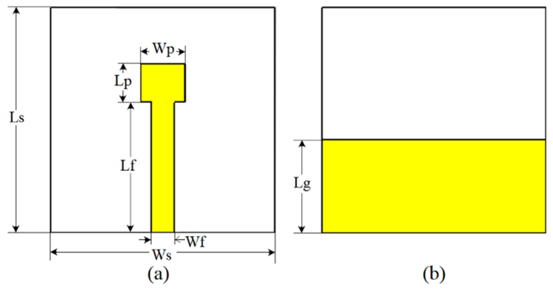
A simple rectangular antenna was introduced to be operated in millimeter wave (mm-wave) to be used for 5G applications. The antenna was produced on a Rogers RT 5880 substrate, measuring 12 × 12 mm2, with a thickness of 0.254 mm and a dielectric constant ( ε r ) of 2.2, featuring a 50 Ω characteristic impedance to match the patch antenna feed, and a partial ground, as shown in Figure 1a,b. All the antenna parameters are presented in Table 1. The main objective of this research was to investigate the effect of inserting ground slots with various shapes and dimensions to achieve a resonant operating frequency suitable for 5G applications. Several slot configurations are also proposed and will be discussed deliberately.
The frequency range selected for evaluating the antenna’s performance was from 10 GHz to 44 GHz.
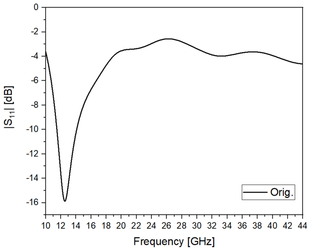
The reflection coefficient (S11) for the tested antenna, without any ground-slot cuts, for the listed parameters in Table 1, is shown in Figure 2.
As shown in Figure 2, the antenna exhibited a single resonant frequency at 12.55 GHz, with a reflection coefficient of –15.9 dB and an operating bandwidth ranging from 11.48 GHz to 14.12 GHz. These results of the reference antenna will later on be compared with other proposed antennas in the next section.

2.2. Design and Parametric Tuning of Ground Slots for Enhanced Antenna Performance

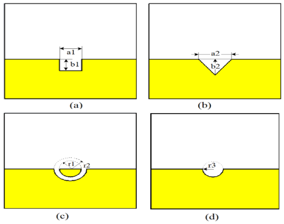
In an antenna system, the ground plane significantly influences the radiation pattern, bandwidth, impedance, and overall efficiency by shaping and directing the signal. Modifying the ground structure, such as inserting a slot, alters the antenna’s performance by shifting the resonant frequency or enhancing efficiency. This paper examines how the different ground-slot designs affected the performance of the antennas. To achieve different operating resonant frequencies and compare them with the original antenna without a slot, “parametric tuning” was done, which refers to selecting the appropriate etched ground-slot size and shape. Depending on its dimensions and geometry, each slot configuration generates different resonant frequencies. These differences were analyzed and compared to ascertain how slot size and shape impacted the antenna’s performance. Four slot designs, including rectangular, triangular, half-ring and half-circular shapes, were analyzed with varying dimensional parameters to determine their effects on some of the crucial antenna performance parameters. Figure 3 shows the four slot geometries that were explored. The four shapes were randomly selected for the experiment; hence, any shape can be tested.

2.2.1. Parametric Tuning of an Antenna with a Rectangular Ground Slot

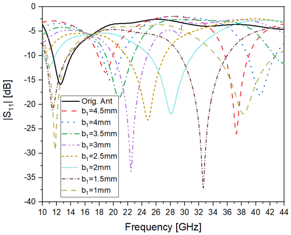
The initial slot was a rectangular shape that was etched in the upper center of the partial ground, as shown in Figure 3a. The slot size, i.e., width (a1) and height (b1), and different dimensions of a1 and b1 were inserted and tested. The optimum width was narrowed down to a1 = 2 mm, chosen as a constant width, while b1 varied from 1 to 4.5 mm in steps of 0.5 mm. Figure 4 shows the reflection coefficient (S11) for each of these configurations, as well as that of the original antenna without a ground slot, enabling direct comparison between them. Table 2 lists a summary of the frequencies of resonant modes, the reflection coefficient, and the operating bandwidth (BW) of the dimensions being experimented with.
From Table 2, it is evident that as b1 increased from 1 mm to 2 mm, the antenna exhibited two resonant frequencies, both of which decreased in value when b1 increased. At b1 = 2 mm, the second resonant frequency was 28 GHz, with a reflection coefficient of −22 dB and an operating bandwidth (BW) of 6 GHz, making it a suitable variant for 5G applications at 28 GHz.
The best reflection coefficient was observed at b1 = 1.5 mm, with resonant frequencies of 11.44 GHz and 32.6 GHz, achieving reflection coefficients of −21 dB and −37 dB, respectively.
For configurations with a single resonant frequency, b1 = 3 mm resulted in a resonant frequency of 22.5 GHz, a reflection coefficient of −33.7 dB, and an operating BW of 4.76 GHz, making it another strong option for 5G applications.
In general, as b1 increased, the resonant frequency decreased, while the reflection coefficient and bandwidth tended to decrease as well.

2.2.2. The Antenna with a Triangular Ground Slot and Its Parametric Tuning

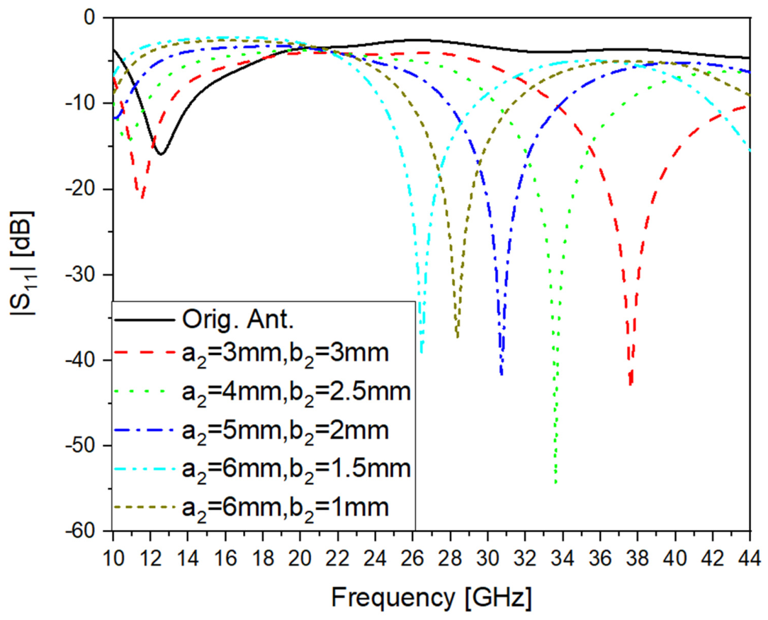
The second slot that was introduced was a triangular slot cut at the center of the partial ground, as shown in Figure 3b. The varying dimensions a2 and b2 were experimented with for the parametric tuning process more than a hundred times, and the best selected values for a2 and b2 were (3, 3), (4, 2.5), (5, 2), (6, 1.5), and (6, 1). The reflection coefficients (S11) for the original antenna and the selected triangular slots are demonstrated in Figure 5. The best-chosen dimensions were compared in terms of resonant frequency, reflection coefficient, and operating BW, and they are listed in Table 3.
From Table 3, it is evident that the first two chosen parameter sets, (a2, b2) = (4, 2.5) and (3, 3), exhibited two resonant frequencies. Specifically, for (4, 2.5),
  • The first resonant frequency at 10.75 GHz achieved a reflection coefficient of −14.8 dB, with a bandwidth (BW) of 1.76 GHz.
  • The second resonant frequency at 33.6 GHz achieved a reflection coefficient of −54 dB, with an operating BW of 6.9 GHz.
Other parameter sets produced a single resonant frequency at
  • A value of 30.7 GHz, with a reflection coefficient of −41.6 dB and a BW of 6 GHz.
  • A value of 26.55 GHz, with a reflection coefficient of −42 dB and a BW of 5 GHz.
  • A value of 28.36 GHz, with a reflection coefficient of −37.3 dB and a BW of 5.4 GHz.
These results indicate that all these resonant frequencies are strong candidates to be used in 5G applications, particularly those falling within the 26.5 GHz to 31 GHz range, which is of significant interest.

2.2.3. The Antenna with a Half-Ring Ground Slot and Its Parametric Tuning

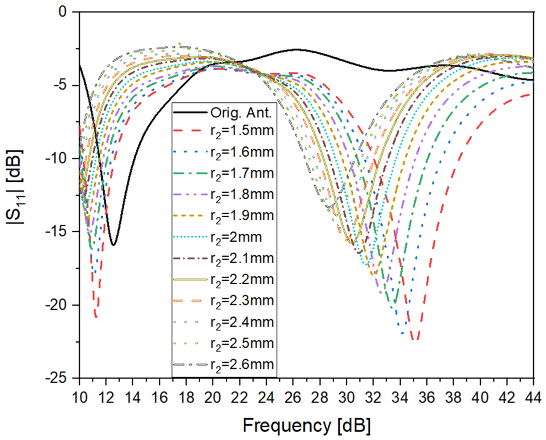
A half-ring slot was also examined in this research, which was located in the upper central part of the ground plane. The main geometric parameters that were under consideration were the inner radius, r1, and the outer one, r2. After a few parametric tuning steps, the inner radius was held constant at 1 mm, with the outer radius being gradually changed from 1.5 mm to 2.6 mm in 0.1 mm steps, as shown in Figure 6. A comparative analysis of the resulting operating bandwidth (BW), reflection coefficient, and resonant frequency of the measurements of the dimensional set tested is displayed in Table 4.
As shown in Table 4, all antenna lengths had two distinct resonant frequencies falling in the range of 1.5–2.2 mm radius (r2). Within this range, a rise in 2 was coupled with a depreciation of the reflection coefficient and a subsequent loss in the operating bandwidth (BW). Figure 5 shows that at 1.9 to 2.2 mm, the bottom edge of the operating bandwidth was less than 10 GHz. The actual bandwidth, therefore, was higher than those in Table 4. To be consistent, however, we chose to take 10 GHz as the lower-frequency limit of all configurations of ground-cut slots, which we are going to consider. When increasing the radius r2 to the range of 2.3–2.6 mm, the system exhibited only one resonant frequency at 29 GHz, a reflection coefficient of −14 dB and an operating bandwidth of about 4 GHz. Lastly, configurations with good performance near the desired frequency underwent follow-up research and parametric tuning to achieve the desired working behavior.

2.2.4. The Antenna with a Half-Circle Ground Slot and Its Parametric Tuning

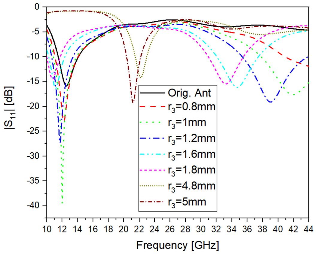
The fourth and last investigated etched slot was a half-circle at the upper center of the partial ground, with which the effect of changing the radius (r3) was tested, as shown in Figure 3d. Seven different values of r3 were chosen through wide parametric tuning, ranging from 0.8 mm to 5 mm. The performance of the antennas with different r3 values was compared with the original design in Figure 7, which displays the results of these variations. Table 5 presents a detailed comparison of the original antenna and the modified version with half-circle cuts.
As the information in Table 5 shows, the closest resonant frequency to that of the original uncut antenna coincided with a half-circular slot with a radius r3 = 0.8 mm. This arrangement provided an operating bandwidth of about 3 GHz and a reflection coefficient of about −23 dB. The next slot, with a radius of 1 mm, achieved a sharp resonant peak at 12 GHz, a reflection coefficient of −39.5 dB and an operating bandwidth of about 3 GHz. This configuration demonstrated that it may be suitable for 5G applications operating at around 12 GHz. The antenna functioned in two bands and had two distinct resonant frequencies for slot diameters of 1.2 mm and 1.6 mm. Larger radii of 4.6 mm and 5 mm, meanwhile, resulted in a single resonant frequency of greater than 20 GHz, indicating that the device was transitioning to higher-frequency operation. This behavior suggests that the slot dimensions could be further selected based on parametric evaluation to make the antenna work better.

3. Discussion and Validation

The proposed design requires developing the antenna to test the empirical data with the simulation results. However, due to financial limitations, physical fabrication was eliminated. As a result, validation is provided by comparing the results of the simulation using our main computational tool with the results of the simulation using the most highly regarded Ansys Electronics Desktop HFSS 2023 platform. The accuracy and advanced capabilities of HFSS are well-known, which makes HFSS a reliable tool in conducting such comparative studies. Nonetheless, it is worthwhile noting that CST and HFSS use fundamentally different numerical techniques: the Finite Integration Technique (FIT) vs. the Finite Element Method (FEM), respectively. Resonance frequencies or reflection values may vary with small variations in mesh types and background boundaries. To create an appraisal that reflects real-world conditions and provides accurate analysis, it is essential that the two simulation environments, CST and HFSS, use the same frequency sampling points. On this note, in the bandwidth investigated (10–44 GHz), each of the simulations had over a thousand discrete frequency points. This is because a high sampling resolution can allow a more precise and reliable evaluation of the simulated responses at the full range of operation.

3.1. Validation for the Original Antenna

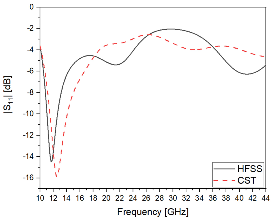
The simulation of the original antenna without any ground-slot cut was done using HFSS, as shown in Figure 8.
As shown in Figure 8, the original antenna exhibited a single resonant frequency at 12.55 GHz, with a reflection coefficient of –15.9 dB and an operating bandwidth ranging from 11.48 GHz to 14.12 GHz. The validation results obtained using HFSS demonstrate a slight variation: the resonant frequency shifted to 11.7 GHz, with a reflection coefficient of –14.46 dB and an operating bandwidth extending from 11 GHz to 12.6 GHz, which shows the consistency of the results across both tools.

3.2. Validation of the Rectangular Cut

First of all, the four different configurations with varying slot dimensions each resulted in either one or two resonant frequencies. To validate the overall work, we focused on the selected configurations that exhibited two resonant frequencies.
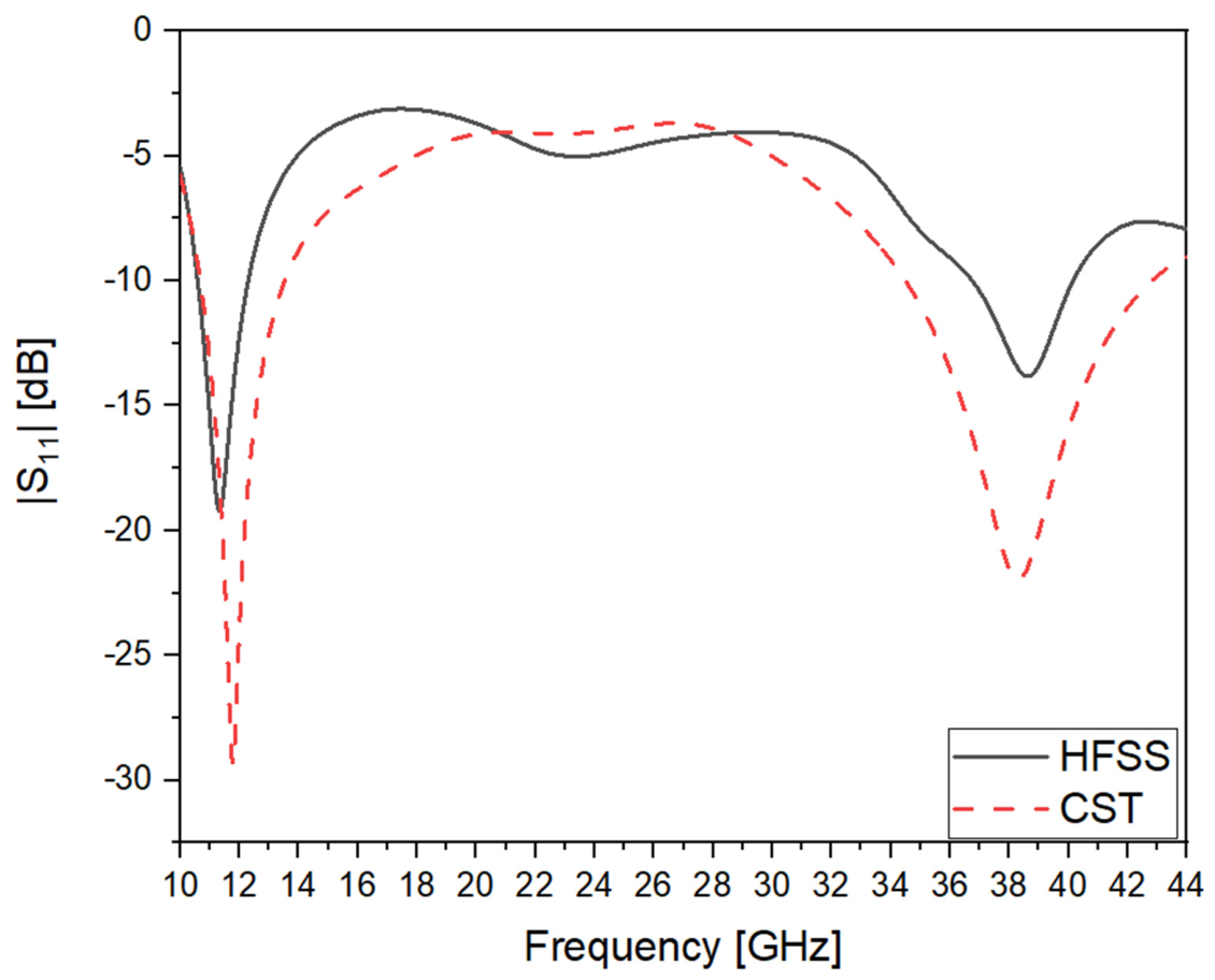
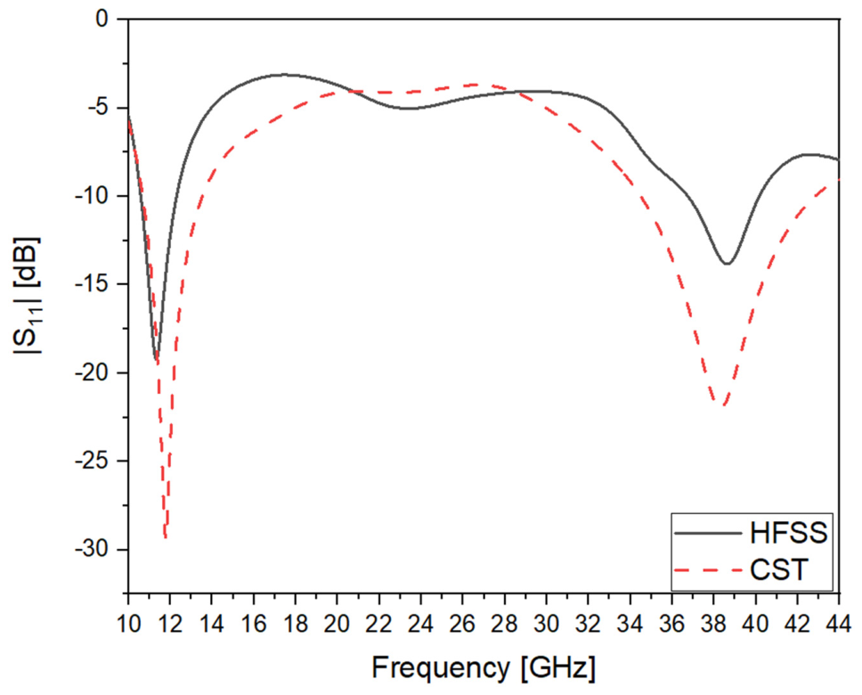
In order to validate the results of the rectangular ground cut, which was investigated using eight different b1 dimensions, we selected the case with b1 = 1 mm. This configuration operated with two resonant frequencies within the bandwidth. A comparison of the simulation results from both CST and HFSS for this case is presented in Figure 9.
From Figure 9, the HFSS simulation showed two resonant frequencies at 11.3 GHz and 38.3 GHz, with reflection coefficients of –19.2 dB and –13.6 dB, respectively. The CST simulation showed resonances at 11.77 GHz and 38.3 GHz, with reflection coefficients of –29.3 dB and –22 dB, respectively, demonstrating good agreement between the two simulation tools.

3.3. Validation of the Triangular Cut

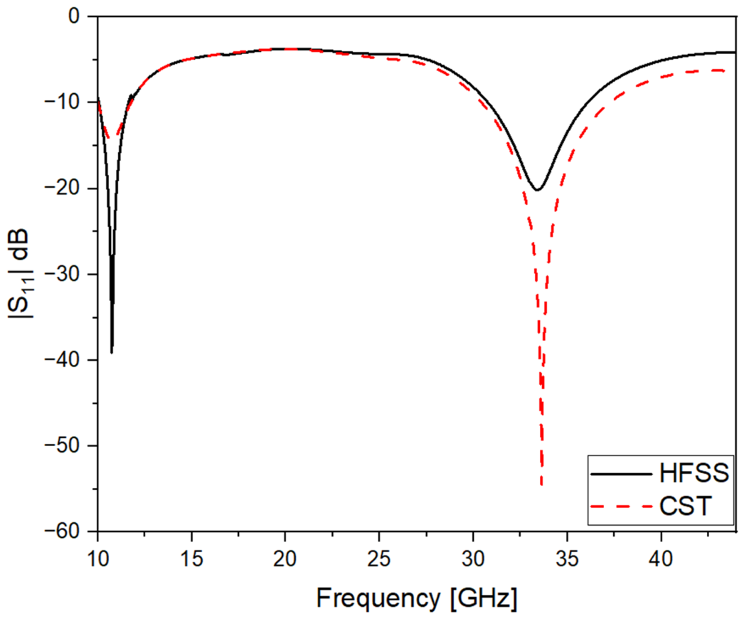
A comparison was then made for the triangular cut with the dimensions of a2 = 4 mm and b2 = 2.5 mm, exhibiting two resonant frequencies: 10.75 GHz and 33.6 GHz. The corresponding reflection coefficients were −14.8 dB and −54 dB, respectively. In the HFSS simulation, the first resonant frequency was observed at the same value (10.75 GHz), but with a better reflection coefficient of −39 dB. However, the second resonance appeared at a slightly different frequency of 33.3 GHz, with a reflection coefficient of −20.15 dB, as shown in Figure 10. From Figure 10, we can see that the first resonance aligned in frequency for both CST and HFSS simulations, with HFSS showing an improved reflection coefficient performance. The second resonance in HFSS received about the same as that in CST but with a lower reflection coefficient of about 33.6 GHz. Despite this shift, the CST result still fell within the operating bandwidth that was observed in the HFSS simulation.

3.4. Validation of the Half-Ring Cut

The comparative analysis of the ring cut was carried out as described below using a dimension of r2 = 1.5 mm. This setup had two resonant frequencies, 11.25 GHz and 35.26 GHZ, with reflection coefficients of −20.8 dB and −22.6 dB, respectively. This was similar to the HFSS simulation, with a slight difference in the results. The initial resonant frequency was found to be 11 GHz, and the resonant reflection coefficient was −22 dB, whereas the second resonant frequency at 35.26 GHz resulted in a resonant reflection coefficient of −16.6 dB. These results are represented in Figure 11. The correlation between the obtained and simulated results was observed to be good, as shown in Figure 11.

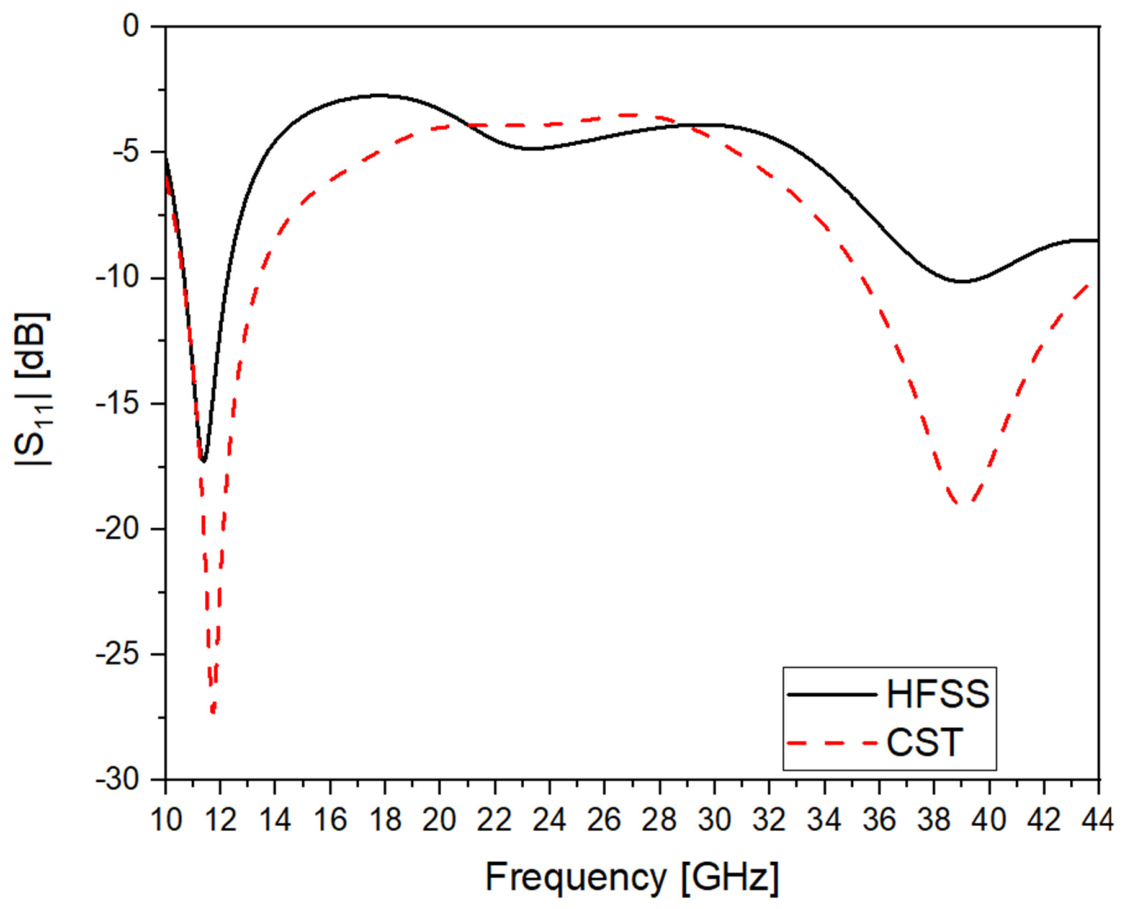
3.5. Validation of the Half-Circular Cut

The fourth comparison was for a half-circular slot with radius r3 = 1.2 mm. This structure had two resonant frequencies of 11.7 GHz and 39 GHz, with corresponding reflection coefficients of −27.3 dB and −19.1 dB. The initial resonance in the HFSS simulation was noted at 11.4 GHz, with a reflection coefficient of −17.2 dB. The latter resonance had the same frequency, 39 GHz, with a poorer reflection coefficient of −10.2 dB, as shown in Figure 12. As can be seen in Figure 12, there was agreement between both simulation tools (CST and HFSS) regarding the resonant frequencies. Nevertheless, the HFSS results showed slightly smaller values for the reflection coefficients than those of the CST simulations, which indicated a slight decrease in performance.

3.6. Parameters of Selected Slot Dimensions

After investigating the four different slots, it was useful to select some of the operating frequencies from each slot to determine the gain, voltage standing wave ratio, current distribution, and, finally, radiation pattern.

3.6.1. The Released Gain

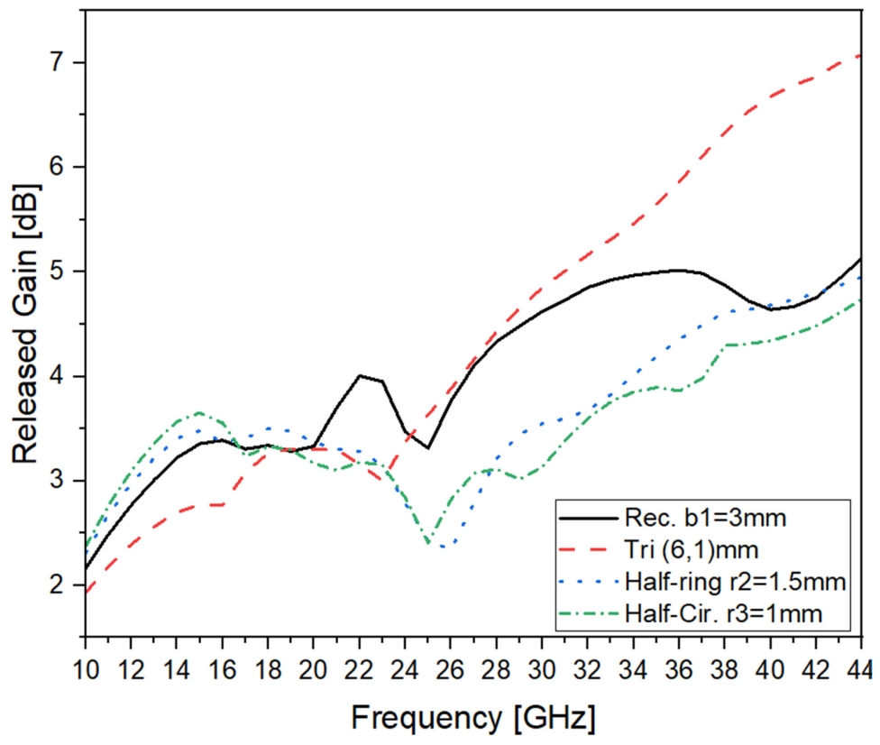
To examine the received operating frequencies in the four different investigated slots, the released gain was investigated for different slot sizes at operating frequencies for a rectangular slot at 22.5 GHz, a triangular slot at 26.55 GHz, a half-ring at 35.26 GHz, and a half-circle at 12 GHz. Figure 13 displays the simulation results, and Table 6 summarizes the results for each antenna slot comparison.
Based on Figure 13, it is evident that the antenna gain was approximately 4 dBi for all investigated slot configurations, which is typical for this type of antenna. The highest gain of 4.2 dBi was achieved by the half-ring slot design, while the lowest gain of 3.09 dBi was obtained with the half-circle slot. Overall, the results indicate that the proposed ground-slot alterations maintained acceptable gain performance while providing frequency-tuning capabilities. The selected antennas that are listed in Table 6, with triangular and half-ring slot cuts, operated at 26.55 GHz and higher frequency bands around 35.26 GHz, which can support mm-wave wireless communication applications, such as 5G bands. It is worthwhile pointing out that not all the received frequencies can be used for 5G applications.

3.6.2. The Voltage Standing Wave Ratio (VSWR)

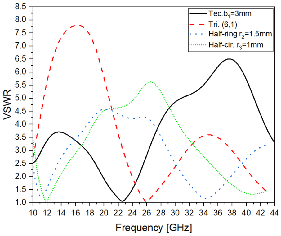
Figure 14 shows the VSWRs at the same chosen frequencies for the gain from the figure. The VASRs were much smaller than 2, and the summary is listed in Table 6. It is evident that all antennas gave a VSWR equal to or less than 1.25.

3.6.3. The Total Efficiency for the Four Different Selected Slot Dimensions

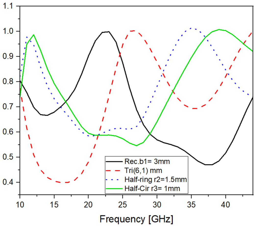
Figure 15 shows the simulated efficiencies for the selected antenna slots. From the figure, it is deductible that for the rectangular slot cut at the selected resonant frequency of 22.5 GHz, the efficiency was very high, amounting to more than 99%. Similarly, for the triangular slot cut at the resonant frequency of 26.55 GHz, the efficiency was more than 99%. Also, for the half-ring slot, the efficiency at the resonant frequency of 35.1 GHz was more than 99%. And finally, for the circular slot cut, the efficiency at the 12 GHz resonant frequency was more than 95%.
The efficiency analysis of the different slots gave an impressive result; it proves that by choosing the right shape and dimension of the slot, whichever it is, one can obtain the desired resonant frequency with good efficiency and gain.

3.6.4. The Radiation Pattern

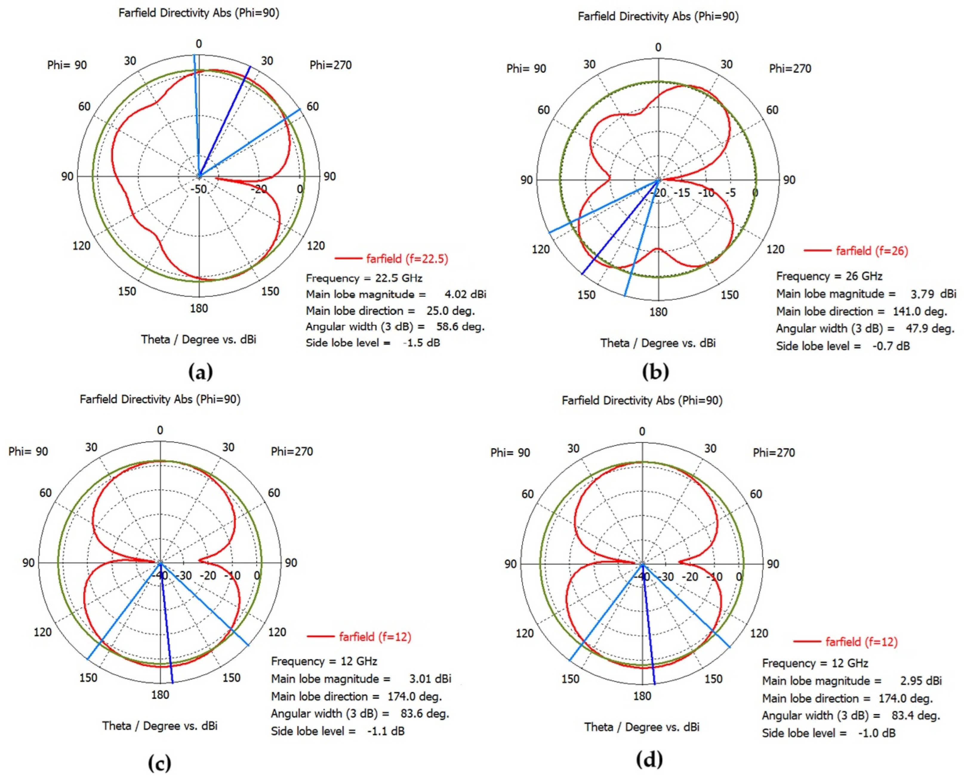
The radiation patterns that were investigated for the selected frequencies that are listed in Table 6 are shown in Figure 16. From Figure 16, it is evident that most of the investigated frequencies radiated omnidirectionally, while for the half-ring, it was approximately directional.

3.6.5. The Surface Current Distribution

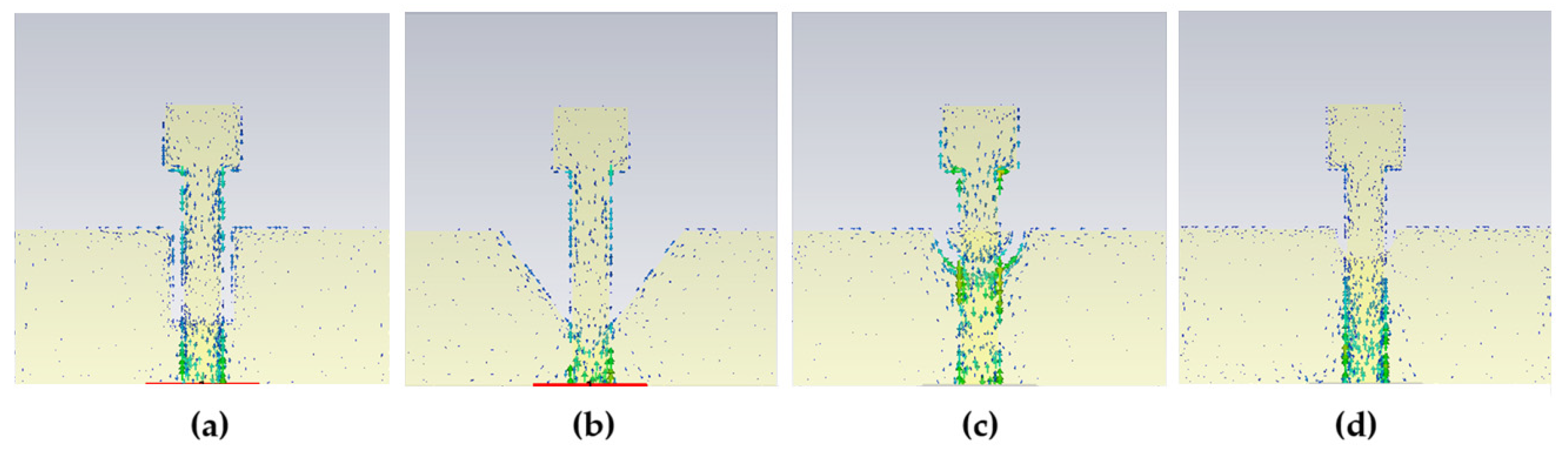
First of all, the investigation of the current distribution was done to study many phenomena, such as choosing a slot to be inserted for the purpose of eliminating an unwanted narrowband in an ultrawideband. In our case, Figure 17 represents the surface current distribution for the different antennas with different slots for the selected operating frequencies for all different slots; the current is concentrated on the feed line until reaching the length of the edge of the slot, except for the half-ring, where it is concentrated around the slot. This is due to the remaining part of the upper ground mimicking the part of the half-ring; from this, the radiation pattern received is not omnidirectional.
Based on the overall simulation results, the selection of the appropriate antenna depends on the desired resonant frequency for the intended application. A summary of the key findings for the four investigated antenna designs can be put forth as follows:
In the first case, involving a rectangular ground slot (as shown in Table 2), with the dimensions of b1 = 3 mm, resulted in a resonant frequency of 22.5 GHz, with a reflection coefficient of −33.7 dB, making it a strong candidate for single-frequency 5G applications. For dual-frequency operation, reducing the dimension to b1 = 1 mm yielded resonant frequencies at 11.77 GHz and 38.3 GHz, with corresponding reflection coefficients of −29.4 dB and −22 dB, respectively. These results indicate that this configuration is also well-suited for 5G applications requiring operation across multiple frequency bands.
Meanwhile, in the second case, when involving a triangular ground slot (as shown in Table 3), all the investigated dimensions produced a single resonant frequency with strong performance. Resonances were observed at 30.7 GHz, 26.55 GHz, and 28.36 GHz, with corresponding reflection coefficients of −41.6 dB, −39 dB, and −37.3 dB, respectively. The selection of dimensions depends on the target resonant frequency for the intended 5G application. Each configuration can be further selected based on parametric evaluation to operate precisely at 30 GHz, 26.5 GHz, or 28.5 GHz through dimensional tuning. Additionally, when the slot dimensions were set to a2 = b2 = 3 mm, the antenna exhibited dual-resonant frequencies at 11.46 GHz and 37.6 GHz, with reflection coefficients of −21 dB and −43.5 dB, respectively. This configuration shows potential for dual-band 5G applications and can be further refined to align with 12 GHz and 38 GHz functionality.
In the third case, when installing a half-ring-shaped ground slot (as shown in Table 4), all investigated dimensions that produced a single resonant frequency operated around 29 GHz, with reflection coefficients of approximately −15 dB. The best-performing configuration was observed with r2 = 1.5 mm, which yielded dual-resonant frequencies at 11.1 GHz and 35.1 GHz, with reflection coefficients of −20.8 dB and −22.6 dB, respectively.
Overall, this ground slot configuration has shown the least favorable results among the cases studied. However, further parametric tuning of the slot dimensions may improve its performance, making it a more viable option for 5G applications.
In the fourth case, when a half-circular ground slot was installed (as shown in Table 5), the best single resonant frequency was achieved with r3 = 1 mm, producing a resonance at 12 GHz with a reflection coefficient of −39.5 dB. This configuration presents a strong candidate for 5G applications at that frequency. Additionally, with r3 = 1.2 mm, the antenna demonstrated dual-resonant frequencies at 11.7 GHz and 39 GHz, with reflection coefficients of −27.3 dB and −19.1 dB, respectively.
Expanded CST–HFSS validation was inserted to emphasize that representative configurations from each slot geometry were validated, and consistent resonant frequencies were observed across CST and HFSS. Minor reflection differences were attributed to solver differences. These results indicate good potential for dual-band 5G operation, given further dimensional fine parametric tuning.
Since the current work was only simulated, it is worthwhile comparing the reported references that have both simulation and fabrication in order to assess how the two results differ, as shown in Table 7. The comparison includes the overall size, resonant frequency, return loss, bandwidth, and gain.
Due to fabrication tolerances, slight variations in the antenna dimensions can affect the reflection coefficient. As a result, there is a slight difference between the measured and simulated results in Table 7, but this difference is within a reasonable range. Meanwhile, the simulated value is about seven times smaller than the measured bandwidth reported in [8].
To assess the robustness of the optimized antenna design against practical fabrication uncertainties, a tolerance analysis was performed by incorporating realistic variations in the substrate dielectric constant, substrate thickness, and critical geometrical dimensions. These parameters were selected because they are among the primary sources of performance deviations in PCB antenna fabrication. The applied tolerance values are representative of standard PCB manufacturing processes and are consistent with typical manufacturer specifications. The selected fabrication tolerances are summarized in Table 8.
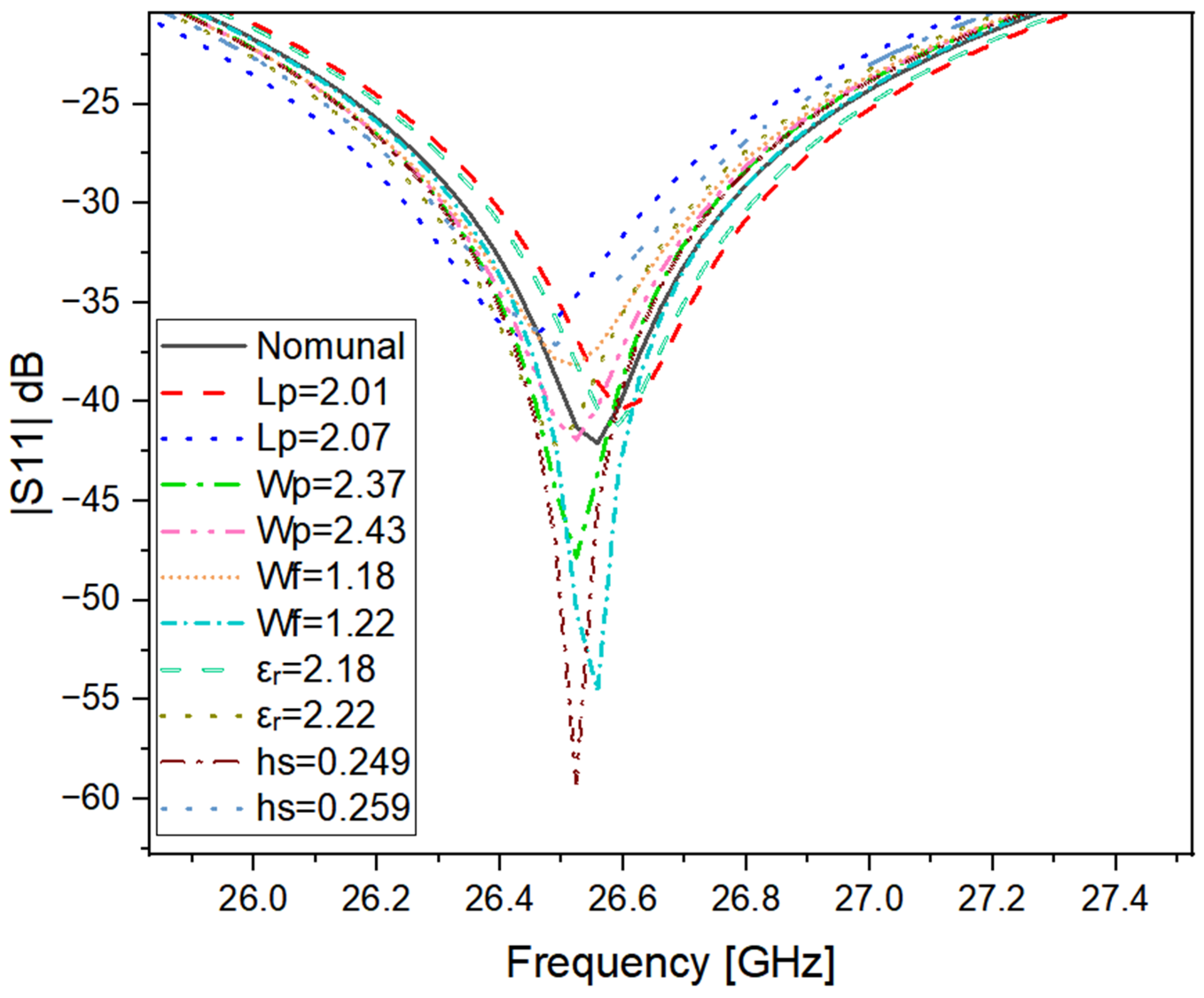
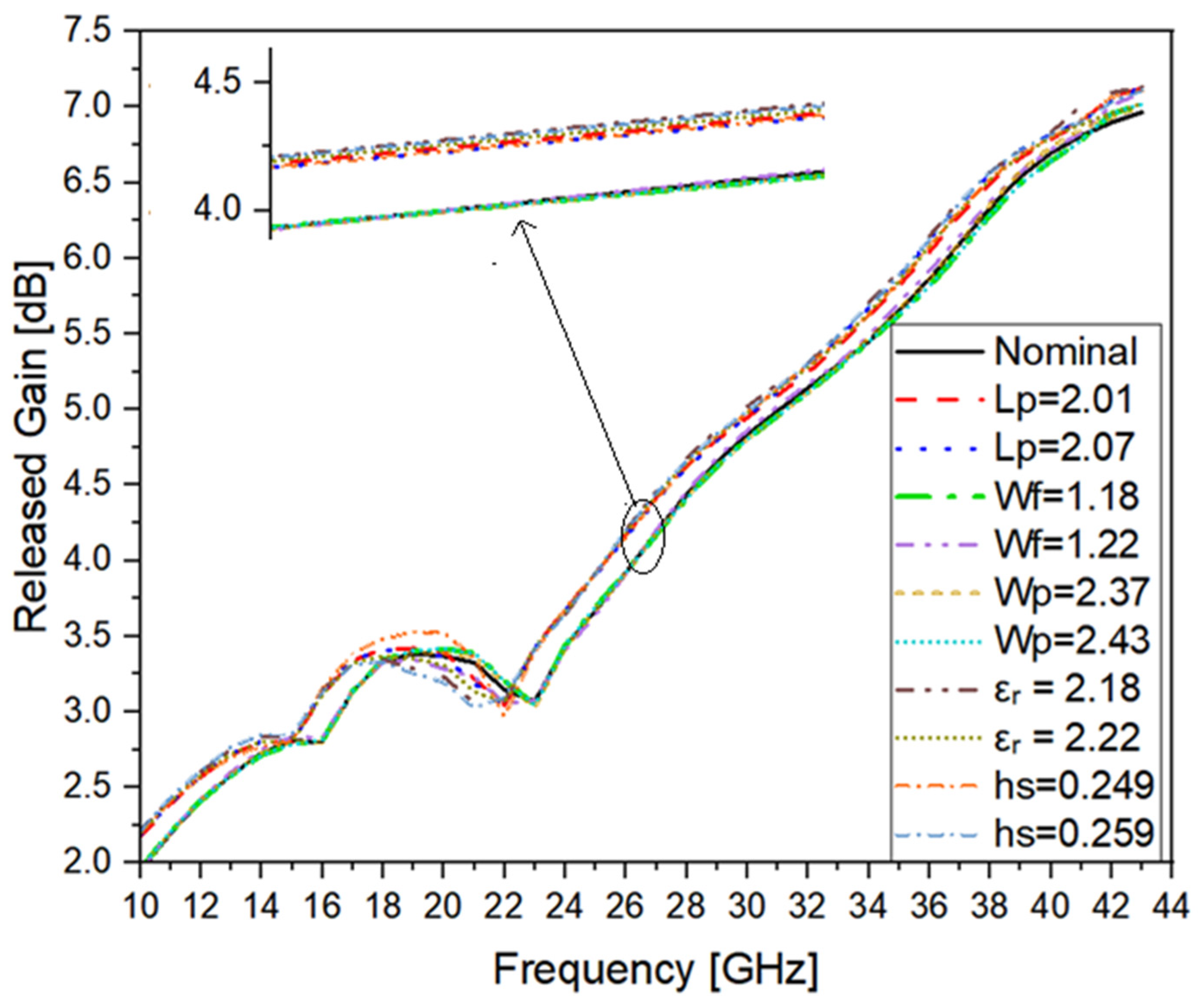
The optimized antenna with the triangular ground slot was chosen as a representative example to investigate the influence of fabrication tolerances. The nominal design values and the parameter variations listed in Table 9 were used in the simulations. The effects of these variations on the antenna performance were evaluated by monitoring the resonant frequency, reflection coefficient (S11), gain, impedance bandwidth, and voltage standing wave ratio (VSWR). The simulated S11 responses are presented in Figure 18 (a magnified view of the region of interest is included to improve the visibility of the small variations among the curves), whereas the corresponding gain-versus-frequency responses are shown in Figure 19.
The statistical results obtained from the tolerance analysis are summarized in Table 10, which presents the mean, standard deviation, minimum, and maximum values of the investigated antenna parameters. For clarity, Table 10 summarizes the results in the form of means ± standard deviation together with the corresponding minimum and maximum values.
Based on the results presented in Table 9 and Table 10, the optimized antenna exhibited only minor performance variations within the considered fabrication tolerances. These findings indicate that the proposed design is robust against typical manufacturing variations, providing additional confidence in the reliability of the simulation results.

4. Conclusions

This study analyzed the effects of varied ground-slot designs, namely, rectangular, triangular, half-ring and half-circular shapes, on the frequency response of a monopole patch antenna, which was manufactured on a Rogers RT 5880 material. The selected four shapes were randomly chosen for the analysis; i.e., any shape could be chosen, and different shapes could have different sizes. This study shows that a simple and effective method for frequency tuning can be achieved by using a ground-slot shape and its dimensions, thereby providing flexibility in defining the intended operating frequency. The reference antenna in the absence of a slot resonated at 12.55 GHz, with a reflection coefficient of −15.9 dB. The addition of ground slots significantly improved the performance by providing novel single or dual-resonant frequencies suitable for 5G deployments. Moreover, an HFSS cross-validation and a fabrication tolerance analysis were performed to further evaluate the proposed antenna. The tolerance analysis considered realistic variations in the substrate dielectric constant, substrate thickness, and the critical geometrical dimensions that may occur during the PCB fabrication process. The obtained results show that these variations have only a limited effect on the antenna performance, indicating that the optimized design is robust to normal fabrication tolerances. This provides additional confidence that the proposed antenna can maintain its performance under practical manufacturing conditions. Overall, the results confirm that introducing ground-slot geometries is an effective approach for frequency tuning and performance enhancement, making the proposed design suitable for 5G and other high-frequency applications.

Author Contributions

Conceptualization, A.H. and M.D.; methodology, A.H., M.D. and F.A.-T.; software, A.H., M.D. and I.T.; validation, A.H., E.D. and S.M.; formal analysis, A.H., I.T. and E.D.; investigation, A.H., F.A.-T., I.T. and S.M.; resources, A.H., M.D., I.T. and F.A.-T.; data curation, A.H., E.D., S.M. and F.A.-T.; writing—original draft preparation, A.H., M.D., F.A.-T., I.T. and S.M.; writing—review and editing, A.H., E.D. and S.M., F.A.-T., I.T., M.D. and S.M.; visualization, A.H., E.D. and S.M.; supervision, M.D., I.T. and F.A.-T.; project administration, M.D. All authors have read and agreed to the published version of the manuscript.

Funding

This research received no external funding.

Data Availability Statement

The raw data supporting the conclusions of this article will be made available by the authors on request.

Conflicts of Interest

The authors declare no conflict of interest.

Abbreviations

The following abbreviations are used in this manuscript:
CSTComputer Simulation Technology
HFSSHigh-Frequency Structure Simulation
5GFifth Generation
mm-waveMillimeter Wave
BWBandwidth
DGSDefected Ground Structure
WLANWireless Local Area Network
Wi-MAXWorldwide Interoperability for Microwave Access

References

  1. Soliman, M.S.; Dwairi, M.O.; Sulayman, I.I.M.A. The Effect of the Ground Slots Up on the Bandwidth Performance for UWB Antenna. In Proceedings of the 2018 18th Mediterranean Microwave Symposium (MMS), Istanbul, Turkey, 31 October–02 November 2018; IEEE: New York, NY, USA, 2018; pp. 68–70. [Google Scholar] [CrossRef] [Scilit]
  2. Al-Dwairi, M.O.; Hendi, A.Y.; Soliman, M.S.; Nisirat, M.A. Design of A Compact Ultra-Wideband Antenna for Super-Wideband Technology. In Proceedings of the 2019 13th European Conference on Antennas and Propagation (EuCAP), Krakow, Poland, 31 March–5 April 2019; IEEE: New York, NY, USA, 2019; pp. 1–4. [Google Scholar]
  3. Al-Dwairi, M.O. A planar UWB semicircular-shaped monopole antenna with quadruple band notch for WiMAX, ARN, WLAN, and X-Band. Int. J. Electr. Comput. Eng. (IJECE) 2020, 10, 908–918. [Google Scholar] [CrossRef] [Scilit]
  4. Al-Dwairi, M.O.; Hindi, A.Y.; Soliman, M.S.; Aljafari, M.F. A compact uwb monopole antenna with penta band notched characteristics. TELKOMNIKA Telecommun. Comput. Electron. Control. 2020, 18, 622–630. [Google Scholar] [CrossRef] [Scilit]
  5. Haider Saeed, N.; Jasim Farhan, M.; Al-Sherbaz, A. Design and Analysis of Microstrip Antenna for 5G Applications. J. Eng. Sustain. Dev. 2024, 28, 285–293. [Google Scholar] [CrossRef] [Scilit]
  6. Syahrial, S.; Nauval, M.W.; Yunida, Y. A Novel Design of Two Circular-shaped Array Microstrip Patch Antenna with Defected Ground Structure for 5G Applications. In Proceedings of the 2023 2nd International Conference on Computer System, Information Technology, and Electrical Engineering (COSITE), Banda Aceh, Indonesia, 2–3 August 2023; IEEE: New York, NY, USA, 2023; pp. 176–181. [Google Scholar] [CrossRef] [Scilit]
  7. Astuti, D.W.; Fadilah, R.; Muslim, D.R.; Rusdiyanto, D.; Alam, S.; Wahyu, Y. Bandwidth Enhancement of Bow-tie Microstrip Patch Antenna Using Defected Ground Structure for 5G. J. Commun. 2022, 17, 995–1002. [Google Scholar] [CrossRef] [Scilit]
  8. Karimbu Vallappil, A.; Khawaja, B.A.; Rahim, M.K.A.; Iqbal, M.N.; Chattha, H.T. Metamaterial-Inspired Electrically Compact Triangular Antennas Loaded with CSRR and 3 × 3 Cross-Slots for 5G Indoor Distributed Antenna Systems. Micromachines 2022, 13, 198. [Google Scholar] [CrossRef] [Scilit] [PubMed]
  9. Gaber, M.A.; El-Aasser, M.; Yahia, A.; Gad, N. Characteristic modes of a slot antenna design based on defected ground structure for 5G applications. Sci. Rep. 2023, 13, 15327. [Google Scholar] [CrossRef] [Scilit] [PubMed]
  10. Chiou, T.-W.; Wong, K.-L. Designs of compact microstrip antennas with a slotted ground plane. In Proceedings of the IEEE Antennas and Propagation Society International Symposium. 2001 Digest. Held in Conjunction With: USNC/URSI National Radio Science Meeting (Cat. No.01CH37229), Boston, MA, USA, 8–13 July 2001; IEEE: New York, NY, USA, 2001; Volume 2, pp. 732–735. [Google Scholar] [CrossRef] [Scilit]
  11. Paul, L.C.; Jim, T.R.; Rani, T.; Ankan, S.S.A.; Das, S.C.; Saha, H.K. A Π-shaped slotted patch antenna with a partial ground structure for lower 5G/WiFi/WiMAX applications. Heliyon 2022, 8, e10934. [Google Scholar] [CrossRef] [Scilit]
  12. Hakeem, M.J.; Nahas, M.M. Improving the Performance of a Microstrip Antenna by Adding a Slot into Different Patch Designs. Eng. Technol. Appl. Sci. Res. 2021, 11, 7469–7476. [Google Scholar] [CrossRef] [Scilit]
  13. Shi, C.; Cui, J.; Renli, Z.; Han, Y. Diamond-shaped metasurface low-profile wideband antenna. J. Eng. 2019, 2019, 6566–6567. [Google Scholar] [CrossRef] [Scilit]
  14. Yusuf, M.A.; Kwaha, B.J.; Umar, I.; Maina, I.; Mohammed, G.; Salihu, A. Line Fed Triangular Microstrip Patch Antenna for Bluetooth Application at 2.45GHz. Phys. Mem.-J. Theor. Appl. Phys. 2019, 1, 22–30. [Google Scholar]
  15. Fadamiro, A.O.; Ntawangaheza, J.D.; Famoriji, O.J.; Zhang, Z.; Lin, F. Design of a Multiband Hexagonal Patch Antenna for Wireless Communication Systems. IETE J. Res. 2019, 68, 1675–1682. [Google Scholar] [CrossRef] [Scilit]
  16. Lee, Y.-H.; Lim, E.-H.; Bong, F.-L.; Chung, B.-K. Bowtie-Shaped Folded Patch Antenna With Split Ring Resonators for UHF RFID Tag Design. IEEE Trans. Antennas Propag. 2019, 67, 4212–4217. [Google Scholar] [CrossRef] [Scilit]
  17. Chandra, R.B.J.; Khan, I.; Devanagavi, G.D.; Sudhindra, K.R.; Ali, T. A circular patch antenna loaded with three complementary ring slots (Crs) for uwb applications. J. Adv. Res. Dyn. Control Syst. 2019, 11, 1214–1220. [Google Scholar]
  18. Lal, K.N.; Singh, A.K. Modified design of microstrip patch antenna for WiMAX communication system. In Proceedings of the IEEE Students’ Technology Symposium, Kharagpur, India, 28 February–2 March 2014; IEEE: New York, NY, USA, 2014; pp. 386–389. [Google Scholar] [CrossRef] [Scilit]
  19. Yan, S.; Zheng, Y. Low-profile Annular Patch Antenna for Pattern Diversity Applications. In Proceedings of the Photonics Electromagnetics Research Symposium—Fall, Xiamen, China, 17–20 December 2019; IEEE: New York, NY, USA, 2019; pp. 222–228. [Google Scholar] [CrossRef] [Scilit]
  20. Verma, R.K.; Srivastava, D.K. Bandwidth enhancement of a slot loaded T-shape patch antenna. J. Comput. Electron. 2019, 18, 205–210. [Google Scholar] [CrossRef] [Scilit]
  21. Liu, W.C.; Yuk, T.I. Bandwidth Improvements Using Ground Slots for Compact UWB Microstrip-fed Antennas. In Proceedings of the 30th Progress in Electromagnetics Research Symposium, Suzhou, China, 12–16 September 2011; Electromagnetics Academy: Cambridge, MA, USA, 2011; pp. 1420–1423. [Google Scholar]
  22. AbuTarboush, H.F.; Al-Raweshidy, H.S.; Nilavalan, R. Bandwidth enhancement for microstrip patch antenna using stacked patch and slot. In Proceedings of the International Workshop on Antenna Technology, Santa Monica, CA, USA, 2–4 March 2009; IEEE: New York, NY, USA, 2009; pp. 1–4. [Google Scholar] [CrossRef] [Scilit]
  23. Deshmukh, A.A.; Mhatre, A.; Shah, M.; Kudoo, C.; Pawar, S. Wideband Designs of Unequal Lengths Slot Cut Microstrip Antennas Backed by Slotted Ground Plane. In Optical and Wireless Technologies; Springer: Singapore, 2020; pp. 363–369. [Google Scholar] [CrossRef] [Scilit]
  24. Kumar, T.M.; Jonathan, N.R.; Peshwe, P.; Doddipalli, S.; Kothari, A. An Annular Ring Antenna with Slotted Ground Plane for Dual Band Wireless Applications. In Advances in Decision Sciences, Image Processing, Security and Computer Vision; Satapathy, S.C., Raju, K.S., Shyamala, K., Krishna, D.R., Favorskaya, M.N., Eds.; Springer: New York, NY, USA, 2020; pp. 307–313. [Google Scholar]
  25. Yuan, J.; Li, Y. A Compact Circularly Polarized Microstrip Ring Antenna Using a Slotted Ground for GNSS Applications. Prog. Electromagn. Res. Lett. 2020, 88, 29–36. [Google Scholar] [CrossRef] [Scilit]
  26. Alkassasbeh, J.S.; Al-Taweel, F.M.; Dwairi, M.O.; Al-Qaisi, A.; Takruri, M. Artificial intelligence-driven optimization of a 34 GHz compact arrow-shaped microstrip antenna for 5G wireless applications. Int. J. Adv. Soft Compu. Appl. 2025, 17, 299–315. [Google Scholar] [CrossRef] [Scilit]
Figure 1. The original investigated antenna, (a) Front view, (b) Back view.
Futureinternet 18 00386 g001
Figure 2. The reflection coefficient of the original investigated antenna.
Futureinternet 18 00386 g002
Figure 3. The investigated different ground slots: (a) rectangular slot, (b) triangular slot, (c) half-ring slot, and (d) half-circular slot.
Futureinternet 18 00386 g003
Figure 4. The reflection coefficient comparison of the original antenna and the proposed antenna with different rectangular ground slots.
Futureinternet 18 00386 g004
Figure 5. Reflection coefficient comparison of the original and proposed antennas with different triangular ground slots.
Futureinternet 18 00386 g005
Figure 6. Reflection coefficient comparison of the original and proposed antennas with varying half-ring ground-slot outer radius (r2).
Futureinternet 18 00386 g006
Figure 7. The reflection coefficient comparison of the original antenna and the proposed antenna with different half-ring circular ground-slot radius r3.
Futureinternet 18 00386 g007
Figure 8. Comparison of simulation results between CST and HFSS for the original antenna without a ground slot cut.
Futureinternet 18 00386 g008
Figure 9. Simulated reflection coefficient S11 comparison between CST and HFSS for the antenna with a rectangular ground-slot cut (b1 = 1 mm).
Futureinternet 18 00386 g009
Figure 10. Simulated reflection coefficient comparison between CST and HFSS for the antenna with a triangular ground-slot cut (a2 = 2 mm and b2 = 2.5 mm).
Futureinternet 18 00386 g010
Figure 11. Simulated reflection coefficient comparison between CST and HFSS for the antenna with a ring ground-slot cut (r2 = 1.5 mm).
Futureinternet 18 00386 g011
Figure 12. Simulated reflection coefficient comparison between CST and HFSS for the antenna with a half-circular ground-slot cut (r3 = 1.2 mm).
Futureinternet 18 00386 g012
Figure 13. The simulated released gain for the four different selected slot dimensions.
Futureinternet 18 00386 g013
Figure 14. The simulated VSWRs for four different selected slot dimensions.
Futureinternet 18 00386 g014
Figure 15. The simulated total efficiencies for the four different selected slot dimensions.
Futureinternet 18 00386 g015
Figure 16. The 2D radiation patterns for the investigated frequencies: (a) rectangular slot, (b) triangular slot, (c) half-ring slot, and (d) half-circular slot.
Futureinternet 18 00386 g016
Figure 17. The surface current distributions for the investigated frequencies: (a) rectangular slot, (b) triangular slot, (c) half-ring slot, and (d) half-circular slot.
Futureinternet 18 00386 g017
Figure 18. Simulated S11 responses of the optimized triangular ground-slot antenna for different fabrication tolerance variations.
Futureinternet 18 00386 g018
Figure 19. Simulated gain versus frequency of the optimized triangular ground-slot antenna under different fabrication tolerance variations.
Futureinternet 18 00386 g019
Table 1. Proposed antenna parameters.
Parameters
mm
Ws, Ls, WgLghsWpLpWfLftp
1250.2542.42.041.26.950.009
a1a2b1b2r1r2r3
22–61–4.51–311.5–2.60.8–5
Table 2. Comparison of different rectangular height dimensions.
AntennaResonant Freq. [GHz]Reflection Coefficient [dB]Oper. BWBW [GHz]
Orig. ant12.55−15.911.48–14.122.64
Antenna with Rectangular Slot, b1 mm111.77, 38.3−29.4, −2210.68–13.54,
34.5–42.8
2.86, 8.3
1.511.44, 32.6−21.1, −3710.45–13.65,
29.4–36
3.2, 6.6
210.87, 28−12.5, −2210.2–11.8,
25–31
1.6, 6
2.524.82−23.221.75–27.25.45
322.5−33.720–24.764.76
3.520.75−1918.9–22.83.9
419.7−15.418.34–21.172.83
4.518.87−13.517.84–19.942.1
Table 3. Comparison of different triangular height dimensions.
AntennaResonant Freq. [GHz]Reflection Coefficient [dB]Operating BW [GHz]BW [GHz]
Orig. ant12.55−15.911.48–14.122.64
Antenna with Tri. Slot (a2, b2) mm(4, 2.5)10.75, 33.6−14.8, −5410–11.76, 30.43–37.31.76, 6.9
(3, 3)11.46, 37.6−21.25, −43.510.46–13, 33.8–442.54, 10.2
(5, 2)30.7−41.627.9–33.96
(6, 1)26.55−42.0924.4–29.45
(6, 1.5)28.36−37.325.9–31.35.4
Table 4. Comparison of different half-ring radius dimensions.
AntennaResonant Freq. [GHz]Reflection Coefficient [dB]Operating BW [GHz]BW [GHz]
Orig. ant12.55−15.911.48–14.122.64
Antenna with Ring Slot Radius r2 [mm]1.511.25, 35.26−20.8, −22.610.3–12.63, 32.06–38.432.33, 6.37
1.611.1, 34.14−17.9, −21.9210.2–12.36, 31.33–37.092.16, 5.76
1.710.92, 33.4−16.14, −20.1510.11–12.06, 30.8–361.95, 5.2
1.810.75, 32.65−15.2, −19.410–11.77, 30.17–35.111.77, 4.94
1.910.58, 32−14.12, −1810–11.5, 29.7–34.41.5, 4.7
210.41, 31.42−13.36, −17.210–11.2, 29.15–33.71.2, 4.55
2.110.27, 30.9−12.7, −16.4210–10.94, 28.7–33.10.94, 4.4
2.210.1, 30.4−12, −15.7510–10.7, 28.3–32.50.7, 4.2
2.329.93−15.5527.95–324.05
2.429.5−14.7227.6–31.53.9
2.529−13.927.22–313.78
2.628.7−13.2826.9–30.63.7
Table 5. The reflection coefficient comparison of the original antenna and the proposed antenna with different half-circular ground-slot radius r3.
AntennaResonant Freq. [GHz]Reflection Coefficient [dB]Operating BW [GHz]BW [GHz]
Orig. ant12.55−15.911.48–14.122.64
Antena with Circular Slot r3 [mm]0.812.21−2311.06–14.063
112−39.510.86–13.883.02
1.211.7, 39−27.3, −19.110.65–13.42, 35.5–442.77, 8.5
1.611.16, 34.6−16.4, −16.210.25–11.35, 32.1–37.51.1, 5.4
1.810.75−14.510–11.751.75
4.622.2−14.2221.5–231.5
521.17−19.2520.36–22.21.84
Table 6. A comparison between the four different slots in terms of resonant frequency, RL, VSWR, BW, and application.
Slot TypeResonant Frequency (GHz)S11 (dB)VSWRGain (dBi)BW (GHz)Application
Rec. (b1 = 3)22.5−33.71.0544.765G
Tri. (6, 1)26.55−42.11.024.0955G
Half-ring (r2 = 1.5)35.1−22.61.254.26.37Dual-band
Half-circle (r3 = 1)12−39.51.063.093.025G
Table 7. A comparison of some simulated and measured results reported in works.
Ref.Overall Size mmRes. Freq. GHz, RL dBBW GHzGain dBi
Sim.Meas.Sim.Meas.Sim.Meas.
[7]26.32 × 20.21 × 1.63.52, −353.57, −343.46–3.823.42–3.918.38-
3.7, −173.66, −12
3.79, −153.73, −32
[8]18 × 34 × 1.63.5, −173.5, −160.10.72.62.3
[11]35 × 31 × 0.793.47, −36.813.51, −262.87–5.47 2.647-
[26]0.38 × 0.38 × 0.038 λgOperating BW At −15 dBOperating BW At −15 dB1.531–1.6971.515–2.524>5-
This work12 × 12 × 0.254Rec. (b1 = 3)22.5, −33.7-4.76-4-
Tri. (6, 1))26.55, −42−25-3.88-
Half-Ring (r2 = 1.5)35.26, −22.6-6.37-4-
Table 8. Typical manufacturing tolerances.
ParameterNominalTolerance
Ls2.04±0.03 mm
Ws2.4±0.03 mm
Wf1.2±0.02 mm
εr2.2±0.02
hs0.254±0.005 mm
Table 9. Nominal design parameters and applied fabrication tolerances for the optimized triangular ground-slot antenna.
 FrS11GainBWVSWR
mm
Nominal26.55−42.14.0951.02
Lp = 2.01 26.59−40.445.11.05
Lp = 2.0726.45−36.64.025.11.03
Wp = 2.3726.52−47.84.045.051.01
Wp = 2.4326.52−423.525.051.02
Wf = 1.1826.52−38.64.055.011.03
Wf = 1.2226.56−54.64.094.951.03
εr = 2.1826.59−41.14.075.051.02
εr = 2.2226.49−42.24.065.021.06
hs = 0.24926.52−59.164.064.981.002
hs = 0.25926.49−37.14.054.931.03
Table 10. Summary of the tolerance analysis results (means ± standard deviation and ranges).
ParameterMean ± SDMin–Max
Fr (GHz)26.527 ± 0.04526.45–26.59
S11 (dB)−43.60 ± 7.54−59.16–36.60
Gain (dBi)4.005 ± 0.1643.52–4.09
BW (GHz)5.022 ± 0.0634.93–5.10
VSWR1.025 ± 0.0171.002–1.060
Disclaimer/Publisher’s Note: The statements, opinions and data contained in all publications are solely those of the individual author(s) and contributor(s) and not of MDPI and/or the editor(s). MDPI and/or the editor(s) disclaim responsibility for any injury to people or property resulting from any ideas, methods, instructions or products referred to in the content.