1. Introduction
The DTT facility is a key pillar of the European fusion roadmap currently under construction at the ENEA Frascati Research Center in Italy. Its mission is to investigate advanced divertor solutions for power-exhaust management in next-generation fusion reactors [
1]. The DTT integrates a wide range of diagnostics, sensors, and actuators [
2] operating under the supervision of CODAS, which orchestrates experiment sequencing, real-time control loops, and data archiving.
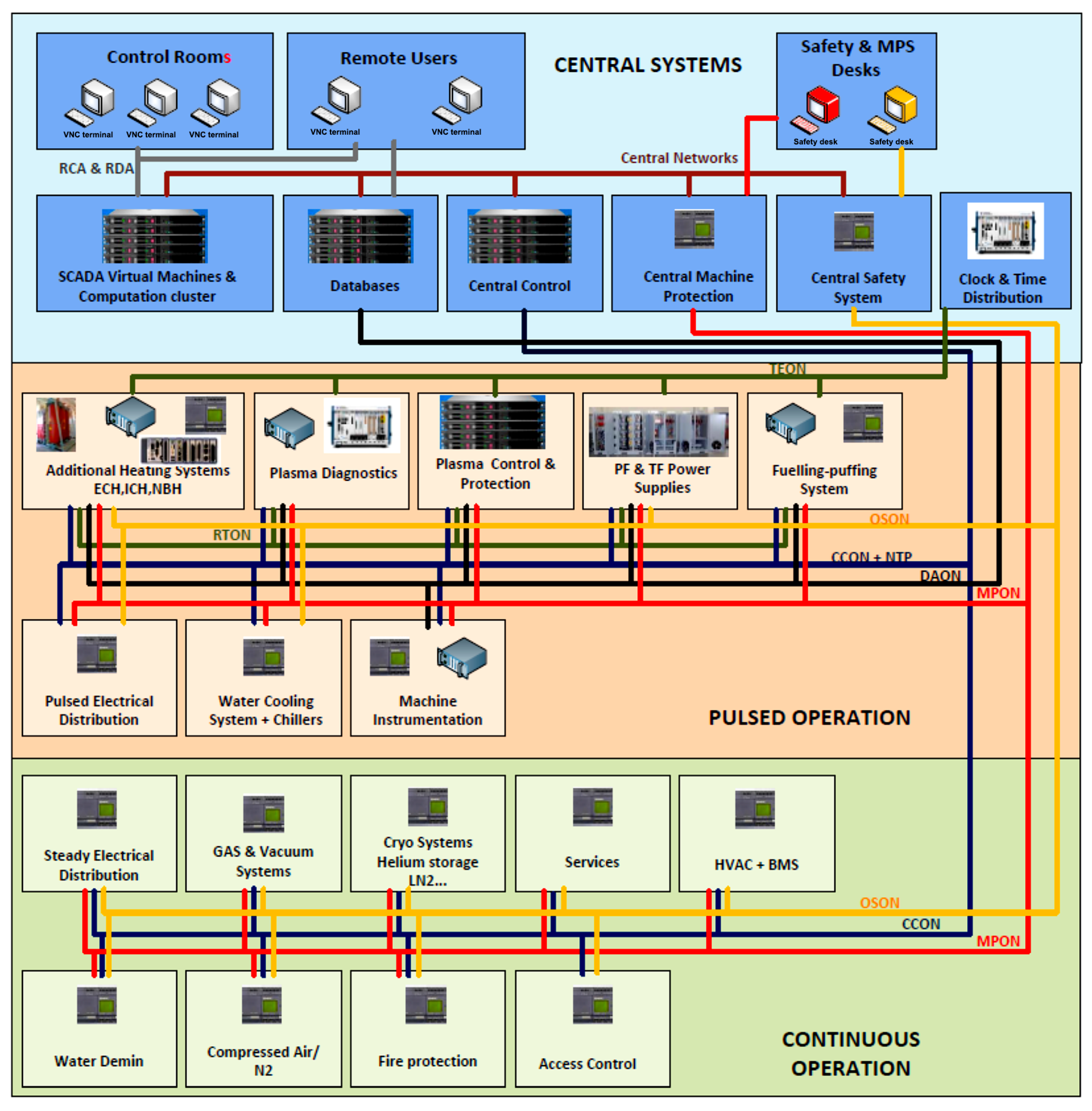
Within the CODAS architecture, time coordination is essential, and communication is structured across four dedicated Ethernet-based sub-networks [
3]. The Central Control Online Network (CCON) exchanges status information and commands between CODAS and plants, while the Data Archiving Online Network (DAON) handles high-throughput data streaming for data-acquisition tasks. The Real-Time Online Network (RTON) manages the exchange of time-critical signals between plant subsystems and the central Plasma Control System (PCS), while the Time Enabling Online Network (TEON) distributes timing information and synchronization messages required to achieve precise, network-based time alignment across all CODAS components as illustrated in
Figure 1. In addition to these, two further networks are present within the architecture: the Occupational Safety Online Network (OSON), responsible for safety-related communications, and the Machine Protection Online Network (MPON), dedicated to machine protection signaling
PCS forms the core of this closed-loop infrastructure, where timing deviations can propagate into control instabilities and inaccuracies in diagnostic measurements. Even sub-microsecond misalignment between sensors and actuators may introduce phase errors, degrade plasma regulation, and compromise the consistency of post-shot analyses.
To address these requirements, a variety of time-synchronization standards have been employed in large-scale scientific and industrial environments, including GPS, Network Time Protocol (NTP), PTP, and White Rabbit (WR). GPS provides nanosecond-level absolute timing but is unsuitable for fusion facilities, where heavily shielded experimental halls prevent reliable reception of satellite signals. NTP, although simple to deploy, is limited to millisecond-level accuracy [
5] and therefore cannot satisfy CODAS timing requirements. PTP is designed for high-precision synchronization over Ethernet [
6] and typically achieves accuracies on the order of 100 ns, which is sufficient for most fusion diagnostics and control operations. WR, an extension of PTP combined with Synchronous Ethernet, further enhances precision into the sub-nanosecond domain [
7]. However, WR infrastructure is more complex and is primarily deployed in large scientific facilities, whereas standard PTP offers a practical balance of accuracy, cost, and integration flexibility suitable for many fusion experiments.
In many fusion facilities, PTP-based synchronization is realized through proprietary PXI-based timing infrastructures or facility-specific hardware platforms. While these solutions achieve high synchronization accuracy, they depend on dedicated chassis, vendor-specific timing modules, and tightly integrated hardware–software stacks, which increase infrastructure cost and limit flexibility. In parallel, numerous FPGA-based PTP implementations attain high precision by integrating complete PTP protocol engines directly in programmable logic (PL) [
8], including custom HDL-based timestamping units, protocol state machines, and clock-control architectures, or by relying on licensed timing IP cores [
9]. Although effective, such approaches increase development complexity, FPGA resource utilization, and long-term maintenance effort.
Recent FPGA SOM platforms such as the KRIA KR260 integrate PTP-compliant hardware timestamping directly within the Ethernet MAC through a dedicated TSU. This feature enables the realization of synchronization nodes without implementing a full fabric-level PTP protocol engine. However, the systematic evaluation of such MAC-integrated SOM architectures as deployment-ready timing nodes within fusion-grade CODAS infrastructures remains unexplored.
The main contribution of this work is the system-level validation of a reconfigurable FPGA-based SOM as a flexible and cost-effective alternative to proprietary PXI-class timing infrastructures for fusion environments. Specifically, this work provides:
System-level validation of a MAC-integrated FPGA SOM with an embedded TSU as a PTP timing node for fusion CODAS environments.
Hardware-level synchronization verification through deterministic PPS generation derived from the PTP-disciplined TSU counter.
Comprehensive multi-hour statistical evaluation of synchronization performance, including PPS offset, network path delay, and clock-servo frequency correction.
By framing the kria KR260 as a compact, software-driven, and reconfigurable timing node, this work establishes a scalable and cost-effective integration methodology for IEEE 1588-based synchronization across TEON and related CODAS networks.
The remainder of this paper is organized as follows.
Section 2 reviews the related work.
Section 3 provides background information on PTP.
Section 4 describes the system overview and the design approach adopted in this study.
Section 5 presents Experimental Validation and Measurement Setup.
Section 6 discusses the experimental results. Finally,
Section 7 summarizes the conclusions and future developments.
2. Related Work
Advancements in large-scale distributed and networked systems, particularly within fusion facilities, have intensified the demand for precise, deterministic, and scalable time synchronization across distributed control and diagnostic subsystems. To address these requirements, several fusion facilities have adopted PTP-based timing systems, which provide nanosecond-level synchronization accuracy over Ethernet networks [
10]. In this context, many facilities have developed custom trigger and timing solutions to meet timing requirements and support deterministic event generation [
11], while others are transitioning their existing timing infrastructures toward PTP-based architectures [
12]. Large-scale facilities such as ITER [
13] have strict synchronization requirements and provide detailed architectural guidelines to ensure deterministic distribution of time, clocks, and triggers across all subsystems. In accordance with these specifications, diagnostic and control modules commonly integrate PTP-enabled receiver boards that track a Grand Master Clock (GMC) and generate synchronized clocks and trigger signals for subsequent stages.
Over the past decade, substantial progress has been reported in hardware-assisted PTP implementations for distributed control and data-acquisition systems in fusion experiments. An early contribution by Jabłoński et al. [
14] presented a PTP-compliant synchronization module for the MTCA.4 platform, achieving an RMS synchronization accuracy of 11.7 ns through hardware timestamping. Building on this work, Sanz et al. [
15] proposed a clock-distribution network implemented on FlexRIO devices within a PXIe infrastructure, employing an NI PXI-6682 timing module as the PTP GMC to meet the timing requirements of the ITER Fast Controller prototype. Owing to their high timing performance and tight integration with commercial software environments, NI PXI-based timing platforms have since been widely adopted across multiple fusion facilities, including the Indian Test Facility (INTF) for the ITER Diagnostic Neutral Beam (DNB) [
16], the EAST tokamak [
17,
18], the HL-2M tokamak [
19], and the MITICA experiment at the ITER Neutral Beam Test Facility (NBTF) [
20].
In the context of long-pulse fusion experiments, Tripathi et al. [
16] reported an event-driven, high-speed data-acquisition system synchronized via IEEE-1588 PTP for the INTF associated with ITER’s DNB. Their hybrid architecture combined conventional low-speed acquisition with a high-speed FPGA-based digitizer (CAEN DT5720), enabling the handling of both synchronous diagnostic events, such as Cavity Ring-Down Spectroscopy (CRDS), and asynchronous events, including high-voltage breakdowns. Time synchronization was achieved using a PXI-6683H timing card as the PTP GMC and PCI-1588 slave cards coordinated through LabVIEW-based real-time software. PPS-based validation demonstrated an RMS timing error below 50 ns under direct network connection.
A more detailed evaluation of PTP-based synchronization in tokamak environments was presented by He et al. [
17] for the EAST tokamak, where a timing system for the poloidal field (PF) power-supply control system was developed using NI PXI-6683H timing boards. The architecture relied on GPS-disciplined clocks and PTPv2 over Ethernet to synchronize multiple PXI slave nodes via PTP-enabled switches. A key outcome of this study was the comparative assessment of standard and real-time Linux kernels, which showed that real-time operation significantly improves synchronization performance, reducing the RMS error from approximately 200 ns to about 35 ns. Following similar design principles, Liu et al. [
19] implemented a high-precision distributed timing system for the HL-2M tokamak using a commercial PTP infrastructure based on HIRSCHMANN IEEE-1588-enabled switches and PXI-6683H timing modules integrated into PXIe chassis. By exploiting Future Time Event mechanisms and LabVIEW-based control, the system enabled flexible and deterministic triggering across subsystems. Experimental validation using PPS measurements demonstrated an RMS timing accuracy of 8.12 ns, with peak deviations confined within ±35 ns.
Addressing ITER-relevant conditions, Trevisan et al. [
20] conducted a comprehensive assessment of PTP-based synchronization for the MITICA (Megavolt ITER Injector & Concept Advancement) experiment at the ITER NBTF, located at Consorzio RFX, Padova, Italy. Their architecture combined a microSync RX201 PTP grandmaster clock (Meinberg Funkuhren GmbH & Co. KG, Bad Pyrmont, Germany), SICOM 3000A PTP-aware switches with Transparent Clock functionality (Kyland Technology Co., Ltd., Beijing, China), and PXI-6683H timing cards at slave nodes (National Instruments, Austin, TX, USA). Using hardware timestamping and high-speed oscilloscope measurements, the authors reported RMS synchronization errors of approximately 11 ns for a single-switch topology and about 18 ns for a two-switch topology, both well within the ITER requirement of maintaining RMS timing errors below 50 ns. In addition, a digital twin of the timing network was developed using OMNeT++ to analyze timing behavior under different configurations, and an Ethernet-based “Lazy Trigger” mechanism was introduced to support event-driven acquisition.
Beyond PXI-based infrastructures, extensive research has also focused on FPGA-based implementations of PTP. As reviewed in [
21], many architectures implement hardware-assisted PTP engines directly in FPGA fabric, incorporating custom HDL-based timestamping modules, protocol state machines, and dedicated clock-control logic. Open-source and commercial IP cores such as HA1588 and hardware-assisted timing cores synthesize timestamping logic at the MAC or PHY layer to improve precision.
Collectively, these studies confirm the technical maturity of PTP-based synchronization in fusion-oriented control and data acquisition systems, particularly when proprietary PXI-based infrastructures or FPGA platforms with hardware-assisted timestamping are employed. Existing works demonstrate that nanosecond-level synchronization accuracy is achievable; however, most implementations either rely on chassis-based commercial timing platforms or integrate substantial protocol functionality directly within FPGA fabric. A systematic system-level evaluation of the KRIA KR260 FPGA SoM, which relies on MAC-level hardware timestamping and software-based clock discipline without implementing a custom fabric-level PTP engine, remains limited in the context of fusion CODAS infrastructures. In particular, long-duration statistical characterization and deployment-oriented validation of such architectures under fusion-relevant conditions have not been comprehensively reported. The present work addresses this gap through the experimental validation of a KRIA KR260 FPGA SoM platform within the DTT timing framework.
3. Precision Time Protocol
PTP, defined in the IEEE 1588 standard, is designed to provide sub-microsecond synchronization accuracy for measurement and control systems while maintaining sufficient flexibility to operate across heterogeneous clock sources. The standard specifies a hierarchical clock architecture and a set of procedures for selecting the best reference clock within a network. This best-clock selection, commonly known as the Best Master Clock Algorithm (BMCA), is performed through the continuous exchange of PTP messages, whose transmission and reception timestamps allow each device to evaluate clock quality. Consequently, the local oscillator of each slave node is disciplined toward the most suitable reference clock in the network. However, the synchronization performance ultimately depends on the accuracy of timestamping, network latency symmetry, and the stability of the local oscillators.
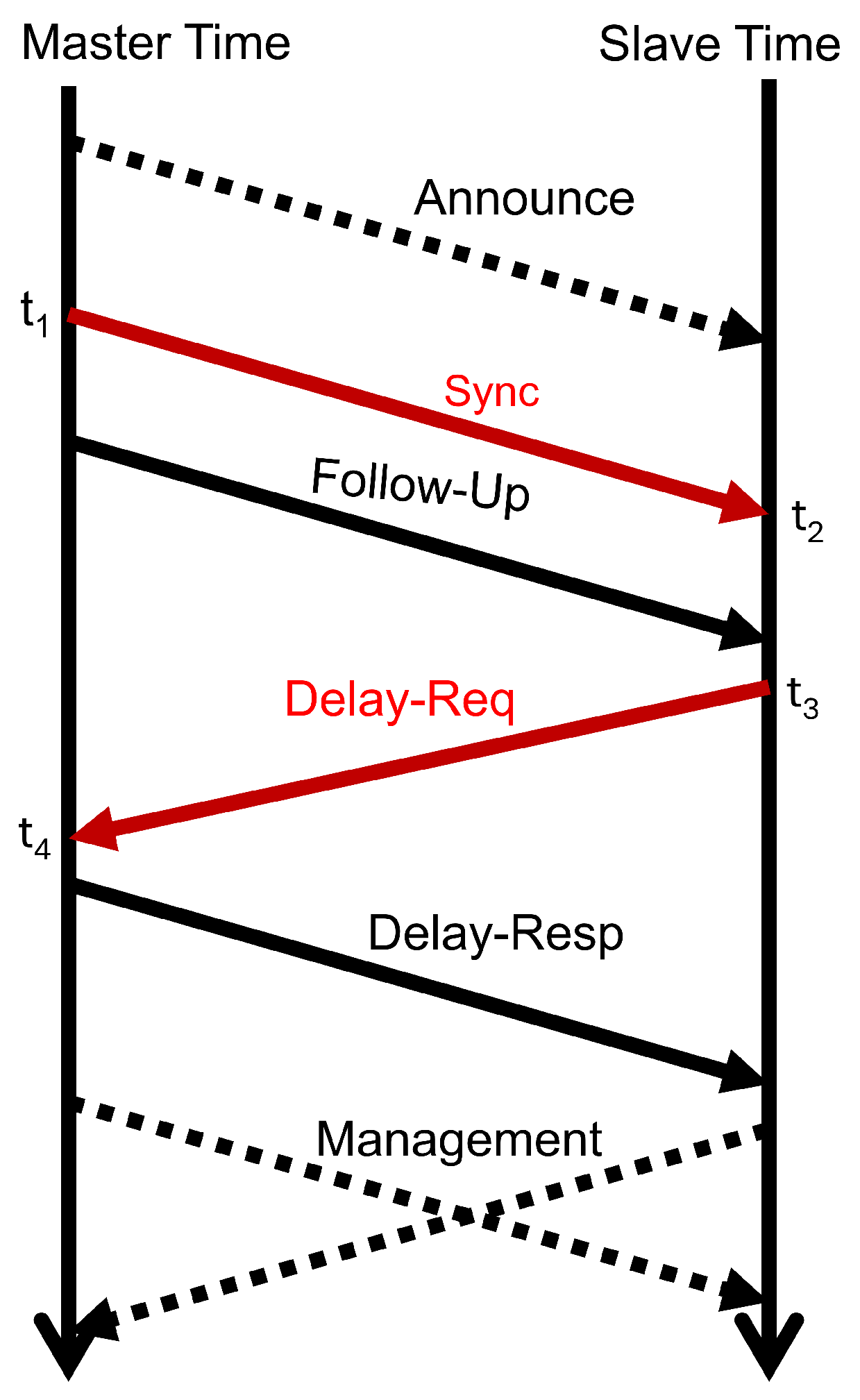
In IEEE 1588 PTP, the offset represents the instantaneous phase difference between the reference and slave clocks and is computed from the timestamps exchanged during the synchronization cycle using the Sync and Delay Req messages as shown in
Figure 2. During each exchange, four timestamps are recorded:
, the transmission time of the Sync message by the master;
, the reception time of the Sync message at the slave;
, the transmission time of the Delay Req message by the slave; and
, the reception time of the Delay Req message at the master. Under the assumption of symmetric propagation delays in both directions, the offset of the slave clock relative to the master is calculated as:
and the corresponding mean path delay is given by:
Here, represents the master-to-slave propagation interval, while denotes the slave-to-master interval. A positive offset indicates that the slave clock lags behind the master, whereas a negative offset signifies that it runs ahead. The ptp4l servo continuously estimates this offset at each synchronization interval and compensates for it by applying phase and frequency corrections to align the slave clock with the master reference.
4. System Overview and Design Approach
This section outlines the system overview and design approach of the proposed synchronization platform developed for DTT CODAS.
The developed synchronization platform is built on the AMD Kria KR260 SoM [
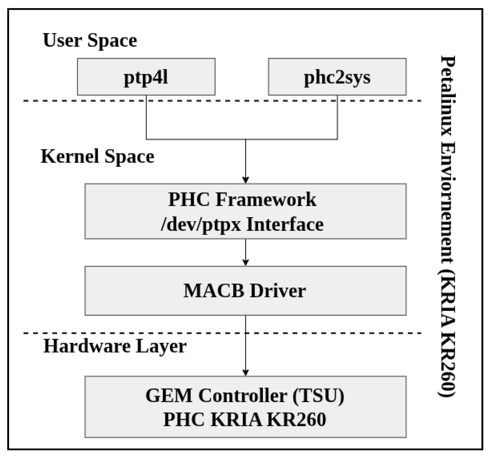
22], which integrates a Zynq UltraScale+ MPSoC comprising a quad-core ARM Cortex-A53 processing system (PS) and FPGA PL fabric. This heterogeneous architecture provides an efficient hardware–software co-design approach. In this work, time-critical functions such as timestamping and signal generation are implemented in the PL, while higher-level synchronization services such as PTP daemons, control logic, and user interfaces execute in the PS under an embedded Linux environment. As illustrated in
Figure 3, the complete system is organized into a four-layer stack running on a customized PetaLinux distribution. At the hardware layer, the Gigabit Ethernet MAC (GEM) controller integrates the TSU and the PTP Hardware Clock (PHC), providing the fundamental timing capabilities. In the kernel space, the MACB driver interfaces directly with the TSU hardware, while the PHC framework exposes the hardware clock to user space through the /dev/ptpX interface.
At the user space layer, two primary PTP components execute: ptp4l, which manages PTP message exchange and performs clock synchronization [
23], and phc2sys, which disciplines the system clock to align with the PHC [
24]. Within this framework, the ptp4l daemon implements the PTP clock servo responsible for correcting the slave clock relative to the master reference. The synchronization process relies on a proportional–integral (PI) control mechanism that continuously estimates the master–slave clock offset using hardware timestamps provided by the TSU. The estimated offset is processed by the PI servo to apply frequency corrections to the local oscillator through the PHC [
25]. In this study, the default hardware timestamping servo gains provided by LinuxPTP were used, with proportional gain
and integral gain
also reported in [
26]. These parameters provide stable offset convergence and effective compensation of oscillator drift under hardware timestamping conditions while avoiding oscillatory behavior in the clock control loop.
The proposed architecture facilitates efficient interaction between hardware and software. To support this architecture, a customized PetaLinux (v2022.2) distribution was developed to include the LinuxPTP stack, GCC utilities, and additional development tools. Kernel modifications were applied to enable hardware timestamping by setting the parameter CONFIG_MACB_USE_HWTSTAMP = y in the Cadence MACB driver. The complete implementation integrates three tightly coupled components: (i) the Vivado hardware design containing the clocking IPs and TSU routing, (ii) the PetaLinux kernel configured for hardware timestamping, and (iii) the LinuxPTP software utilities for PTP message handling and servo control.
To provide a hardware-level validation of synchronization performance, a PPS signal is adopted as the observable timing reference instead of relying on Time of Day (ToD) comparison or hardware loopback methods. The ToD clock is maintained in hardware by the TSU counter; however, its comparison requires register readout through software interfaces, which introduces access latency and operating-system-induced uncertainty. Hardware loopback, on the other hand, characterizes internal signal paths within a single node and does not reflect end-to-end synchronization across distributed devices. In this work, the objective is to assess the relative phase alignment between master and slave nodes over the network. Therefore, PPS edge-to-edge offset measurement is employed, as it provides a direct physical-layer evaluation of synchronization error with nanosecond resolution, independent of software readout effects.
In the Zynq UltraScale+ architecture, the TSU implements a 102-bit hardware timestamp counter. When GEM0 is enabled on the KR260 platform, the TSU counter is externally exposed as a 94-bit signal, where the upper 48 bits represent the seconds field and the remaining 46 bits represent the fractional field corresponding to nanoseconds and sub-nanoseconds. Bit 46 corresponds to the MSB of the fractional field and changes state once per second as the fractional counter completes one full cycle and rolls over while incrementing the seconds field. As a result, the transitions of this signal provide an inherently synchronized hardware-derived PPS timing reference.
The TSU was clocked using a 250 MHz reference generated through a Clocking Wizard IP via the EMIO interface, providing a counter resolution of 4 ns per tick. This resolution is sufficient to support the sub-100 ns synchronization accuracy required for CODAS timing validation. The EMIO clock path was selected to ensure that the exposed 94-bit timer signal remains synchronous with the PL clock domain, while the Clocking Wizard IP provides a clean, phase-stable, and jitter-attenuated clock source isolated from other PS peripherals. The resulting PPS signal therefore represents a deterministic hardware timing reference derived directly from the PTP-disciplined TSU counter. This internally generated PPS signal served as the primary observable reference for assessing master–slave synchronization performance during experimental validation.
Each node was configured using a dedicated PTP configuration file specifying clock type, delay mechanism, and servo parameters. The master node was set with slaveOnly = 0, priority1 = 100, and priority2 = 128 to ensure master selection, while the slave node used slaveOnly = 1, priority1 = 255, and priority2 = 64 to enforce slave operation. Both nodes were configured as ordinary clocks (OC) using UDPv4 transport and the end-to-end (E2E) delay mechanism. Upon system startup, ptp4l was launched on both nodes, and phc2sys was executed on the slave to align the system clock with the local PHC. The Ethernet interface eth1 corresponds to GEM0, whose TSU counter is visible to user space as /dev/ptp0. Hardware timestamping functionality was verified by reading raw PHC values through the command phc_ctl eth1 get, which correctly returned continuously incrementing timestamps once the Vivado bitstream and kernel drivers were loaded.
5. Experimental Validation and Measurement Setup
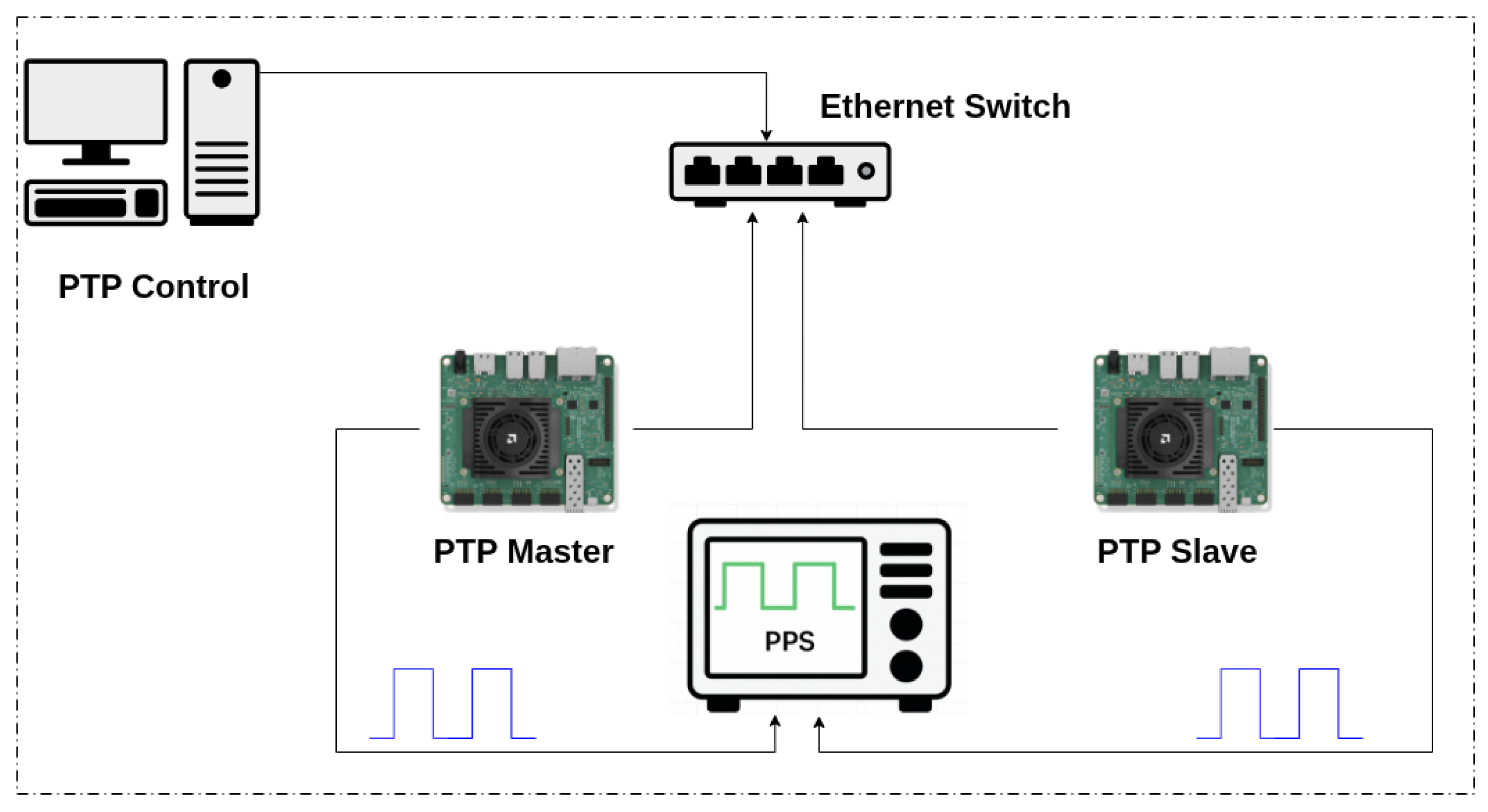
To validate the proposed synchronization design approach, an experimental evaluation was conducted using two AMD Kria KR260 boards interconnected through a dedicated Gigabit Ethernet network, as shown in
Figure 4. The boards were connected via a single Ethernet switch to ensure a stable and controlled communication path. Both devices booted from customized PetaLinux images stored on SD cards, with one board configured as the PTP master and the other operating as the PTP slave. The PPS output signals generated by both boards were connected to an external high-resolution oscilloscope, enabling direct time-domain comparison of the PPS waveforms and precise measurement of synchronization performance.
The measurements were performed using a Teledyne LeCroy HDO6104B (Chestnut Ridge, NY, USA) high-definition oscilloscope (1 GHz bandwidth, 12-bit resolution). The PPS signals were acquired at a sampling rate of 5 GS/s using identical 10× passive voltage probes connected to adjacent analog channels. According to the manufacturer’s specifications, the oscilloscope provides a timebase accuracy of
ppm
ppm/year and a typical inter-channel timing jitter of 2 ps RMS for analog channels [
27]. Since both PPS signals were captured simultaneously using the same internal timebase, absolute clock accuracy does not affect the relative edge-to-edge comparison. No manual channel deskew calibration was applied. Identical probe models and symmetric channel connections were used to minimize inter-channel delay mismatch. The instrumentation-related timing uncertainty is therefore significantly smaller than the nanosecond-level synchronization offsets reported in this work.
The experimental workflow consisted of five sequential stages. In the first stage, the two boards operated independently, and the generated PPS signals were measured prior to enabling the LinuxPTP service to determine the initial clock offset between the nodes. In the second stage, the PTP synchronization process was initiated by running the ptp4l and phc2sys daemons, allowing the clock-servo loop to converge until steady-state operation was achieved. In the third stage, PPS waveforms were captured at high resolution, and ptp4l logs were recorded to extract network path-delay and clock frequency-adjustment data. In the fourth stage, Python-based (Version 3.9.25) analysis scripts were employed to process the acquired data and compute statistical parameters, including mean offset, standard deviation, and path-delay variation over time. Finally, synchronization accuracy was assessed through comparative analysis of the aligned PPS signals to confirm nanosecond-level performance between the master and slave boards.
6. Results and Discussion
This section presents and discusses the experimental results obtained from the evaluation of the PTP-based synchronization system. The analysis highlights the implications of the measured performance for timing-sensitive applications within the DTT CODAS. The synchronization behavior between the master and slave nodes was evaluated using the experimental configuration illustrated in
Figure 4. In the absence of synchronization, independent oscillators in the two KR260 boards would operate with slight frequency differences, resulting in a phase offset between their generated timing signals. When the PTP service is enabled, the slave clock is disciplined to the master reference through continuous timestamp exchange and clock correction performed by the LinuxPTP stack. This process ensures that the slave hardware clock tracks the master time reference while compensating oscillator drift and network delay variations.
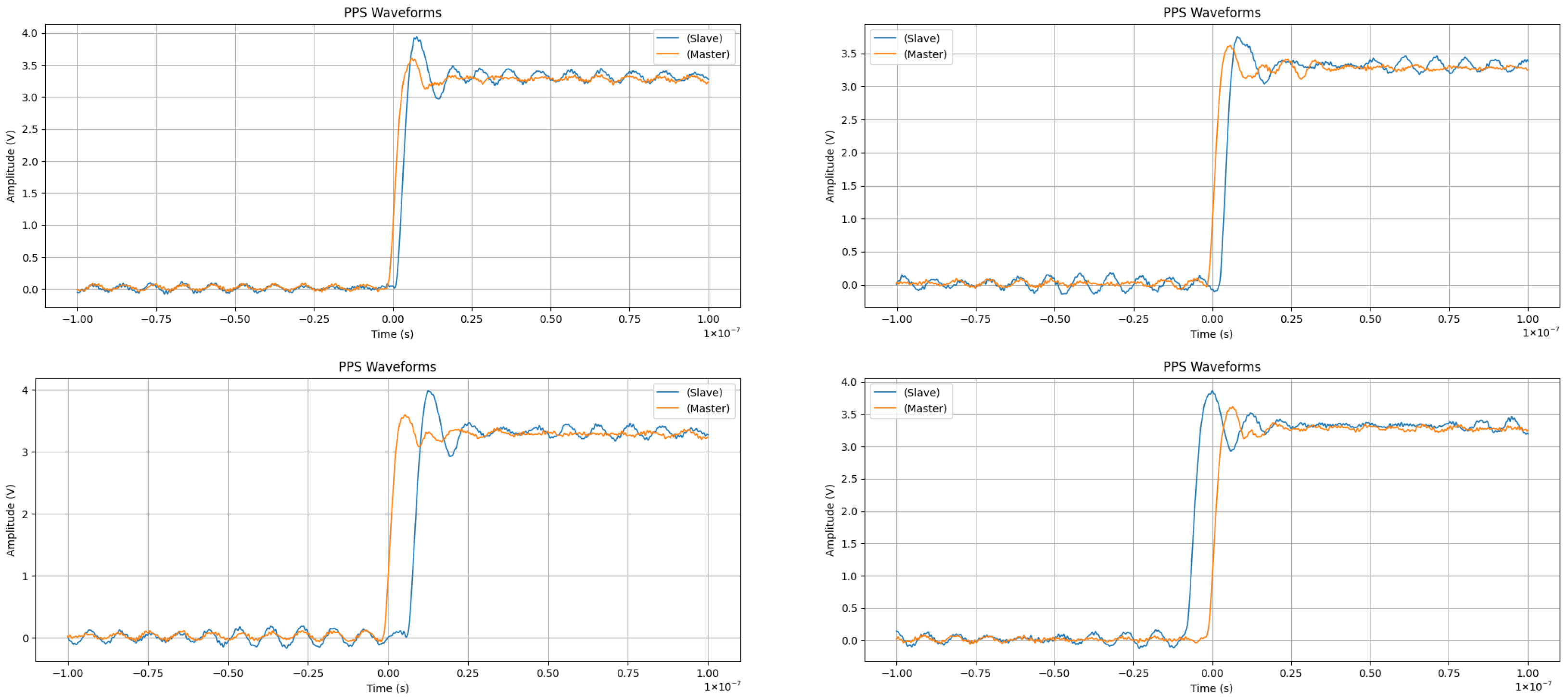
To quantitatively evaluate synchronization performance, the experiment was conducted for a duration exceeding five hours. PPS waveforms were acquired at a sampling rate of 5 GS/s to enable high-resolution timing analysis. Representative waveform samples used for offset estimation are shown in
Figure 5. The high sampling rate allows precise detection of the rising edges of the master and slave PPS signals, enabling accurate estimation of the time offset and delay between the synchronized nodes.
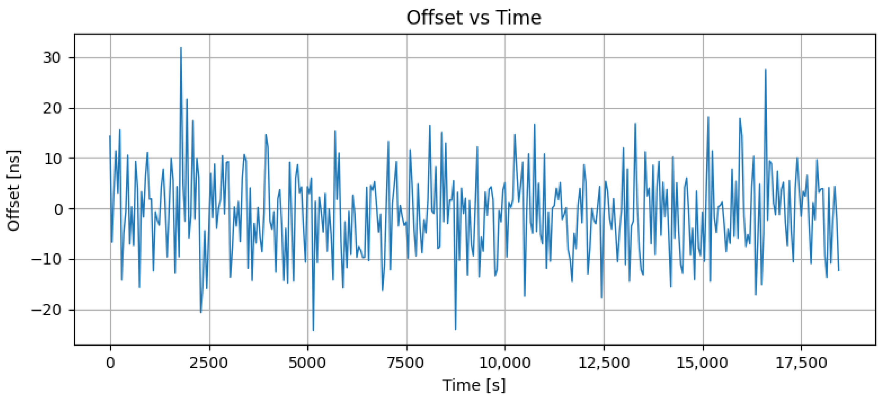
A total of 9245 PPS pulses were acquired during the experiment. The timing offset for each pulse was computed by detecting the rising edges of the master and slave PPS signals using a fractional-sample interpolation technique, providing sub-nanosecond resolution. Across the full dataset, the system achieved a mean offset of
ns and an RMS synchronization error of
ns, with a standard deviation of
ns.
Figure 6 presents the offset evolution over time, and
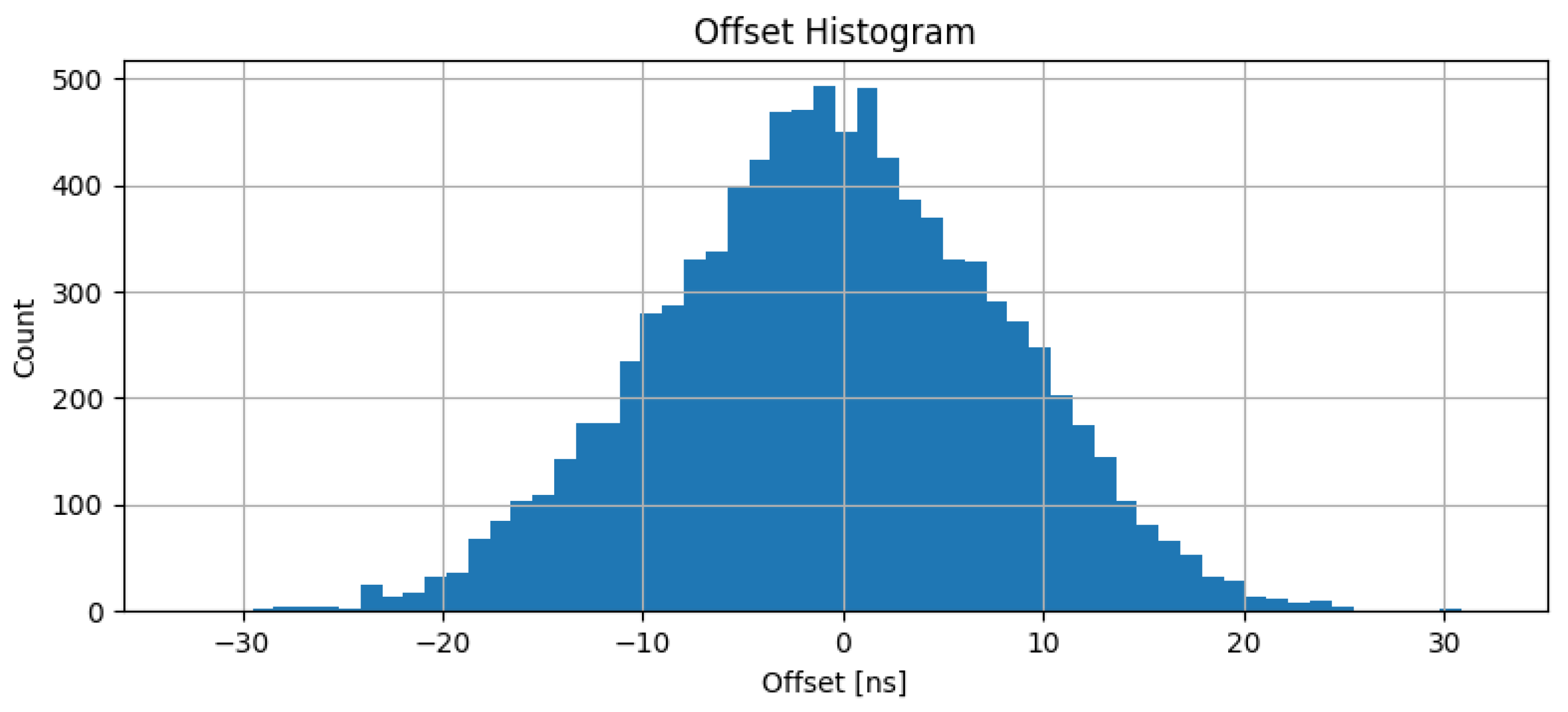
Figure 7 illustrates the statistical distribution of clock offsets over the entire acquisition period. A summary of the statistical results is provided in
Table 1. These statistical indicators provide insight into the stability characteristics of the synchronized clocks. Long-term clock stability is assessed through the offset time series shown in
Figure 6. The offset remains bounded throughout the five-hour observation period without exhibiting any systematic drift or increasing trend, indicating that the frequency difference between the master and slave oscillators is effectively compensated. The approximately Gaussian distribution of offsets shown in
Figure 7, centered near zero with no significant asymmetry, further indicates that the residual synchronization error is dominated by random noise rather than systematic effects, which is consistent with stable closed-loop clock discipline over the entire acquisition period.
The near-zero mean offset of −0.59 ns indicates the absence of any significant systematic timing bias. The small residual mean can be attributed to minor static path-delay asymmetry arising from differences between the forward and reverse propagation paths, which the End-to-End delay compensation mechanism cannot fully eliminate. The RMS synchronization error of 8.51 ns reflects the combined contribution of two principal noise sources: network-induced path-delay jitter, evidenced by the measured path-delay standard deviation of 2.50 ns, and residual short-term oscillator phase noise. Occasional offset excursions reaching approximately ±32 ns are likely caused by transient network delay variations, from which the system quickly recovers within one to two synchronization cycles.
In parallel with the PPS-based measurements, PTP log data were collected to analyze network latency and clock-servo behavior.
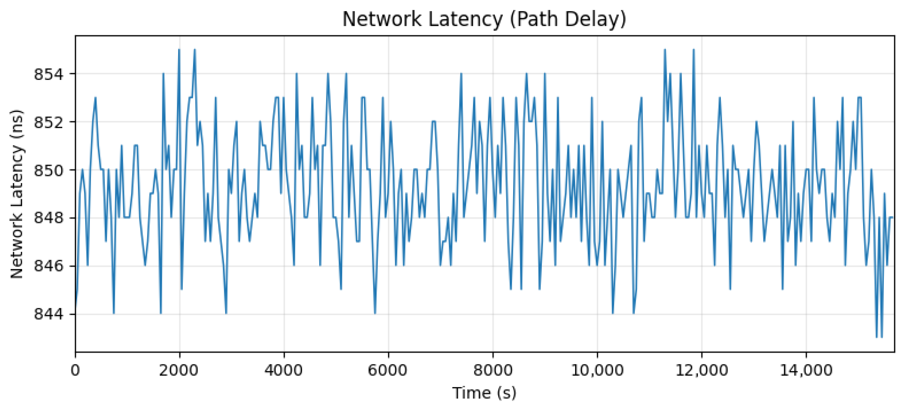
Figure 8 shows the estimated one-way network path delay between the master and slave nodes, computed as half of the round-trip delay in accordance with the PTP delay-request mechanism. The path delay remained highly stable throughout the experiment, with a mean value of
ns and a standard deviation of
ns, indicating a consistent and symmetric network path under the controlled laboratory conditions. The low path delay variation is consistent with the dedicated Gigabit Ethernet link used in the experimental setup, which minimizes switch-induced queuing delays and competing traffic from the PTP timing path. Under these controlled conditions, the measured delay primarily reflects the intrinsic propagation characteristics of the link. In a practical deployment environment, however, the presence of intermediate network switches, background traffic, and longer cable paths may introduce additional packet delay variation and increase synchronization uncertainty. This consideration motivates the use of PTP-aware network elements, such as transparent or boundary clocks, in the future TEON timing infrastructure to mitigate network-induced timing variability.
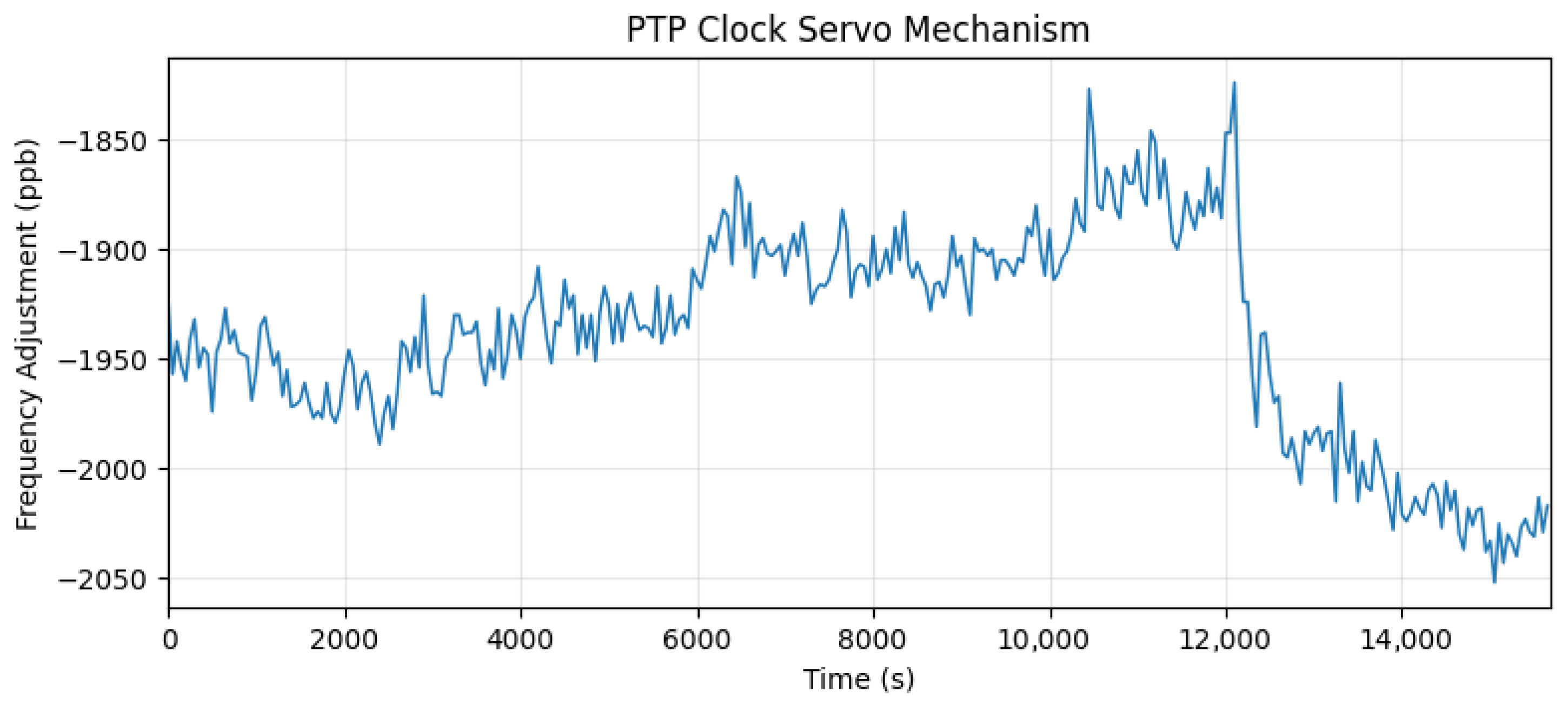
Figure 9 illustrates the clock-servo frequency adjustment applied to the slave oscillator over the full acquisition period. The correction values, expressed in parts per billion (ppb), represent the fine-grained frequency tuning performed by the control loop to maintain long-term synchronization. The frequency adjustment exhibits a mean value of
ppb with a standard deviation of 47 ppb, indicating that the slave oscillator naturally runs slightly faster than the master and is continuously slowed to maintain phase alignment. A noticeable deviation in the frequency correction is observed around 11,600 s, which is also reflected as a temporary disturbance in the PPS offset measurements. This event can be interpreted as the transient response of the clock control loop to a short-term disturbance affecting the synchronization process. In such cases, the proportional component reacts immediately to the offset variation, producing a brief frequency correction spike, while the integral component gradually restores the steady-state correction. The rapid recovery observed after this event indicates that the control loop remains stable and effectively compensates short-term disturbances. Overall, the bounded nature of the frequency adjustment confirms robust long-term clock stability throughout the entire observation period.
Overall, the experimental results demonstrate nanosecond-level synchronization accuracy, low path-delay variation, and stable long-term clock discipline under controlled conditions. These results confirm the feasibility of the proposed approach for distributed timing applications in fusion-oriented CODAS environments. To assess the obtained synchronization performance with respect to existing timing solutions, a quantitative comparison with representative PTP timing platforms reported in the literature is summarized in
Table 2. The comparison includes the timing platform architecture, reported RMS synchronization accuracy, and the corresponding deployment application.
As shown in
Table 2, the synchronization accuracy achieved by the proposed KR260-based timing node (RMS ≈ 8.5 ns) is comparable to that of widely used commercial PXI-based timing systems and other PTP implementations reported in fusion facilities such as ITER, EAST, and HL-2M. The proposed solution reduces hardware complexity by eliminating the need for dedicated PXI chassis, licensed timing IP cores, and fully custom FPGA-based PTP engines. Consequently, the KR260-based platform represents a flexible and reconfigurable synchronization node suitable for scalable deployment in fusion-grade CODAS environments, while maintaining nanosecond-level timing performance comparable to that of industrial-grade timing systems.
7. Conclusions and Future Work
This paper has presented a practical solution for high-precision clock synchronization using a low-cost FPGA platform. In the proposed approach, the hardware design has been intentionally kept simple, relying on the integrated TSU of the Kria KR260 and a dedicated PPS generation module derived from the synchronized PTP clock. The complexity of the timing alignment process is handled primarily in software through LinuxPTP, which continuously compensates for oscillator drift and maintains frequency alignment. The nanosecond-level accuracy obtained in the presented experiments, characterized by a mean offset of −0.59 ns and an RMS synchronization accuracy of 8.5 ns across 9245 PPS pulses, demonstrates that the Kria KR260 platform can deliver synchronization performance well beyond the typical requirements of CODAS systems, where accuracies on the order of 100 ns RMS are commonly sufficient. The measured stability in offset, path delay, and servo frequency adjustment further confirms the robustness of the proposed approach. The built-in hardware timestamping capability of the Kria platform, together with software control through PetaLinux, makes the system a low-cost, flexible, and fully customizable solution for distributed diagnostic and control systems in fusion facilities.
The experimental validation presented in this study provides an initial baseline assessment of the proposed synchronization architecture. The experiments were conducted under controlled laboratory conditions using a two-node configuration in order to isolate and accurately assess the intrinsic synchronization performance of the KR260-based timing platform. At the current stage, the DTT facility is still under development, and the full TEON timing network has not yet been deployed. Consequently, performing controlled validation prior to large-scale integration is necessary to establish a reliable performance baseline.
We are currently extending this work toward a general-purpose timing generator capable of producing synchronized 10 MHz reference clocks and configurable trigger patterns for a broad range of diagnostic needs. As a next step, the developed timing module will be integrated into the DTT CODAS network through the TEON communication layer, where its performance will be evaluated under multi-node and switched-network conditions to assess long-term stability and synchronization behavior in a realistic operational environment.