1. Introduction
The Digital twin (DT) has emerged as a transformative technology within the landscape of smart manufacturing and Industry 4.0. Its capability to seamlessly integrate virtual and physical environments has positioned digital twins as recognition a key innovation, garnering significance in both academic research and industrial applications. Since its inception, the DT concept has enabled numerous successful implementations across diverse industries, including product design, production optimization, predictive maintenance, and operational management [
1]. Despite the increasing adoption of digital twin technology, a limited number of comprehensive reviews exist that focus specifically on its industrial applications [
2,
3]. This gap highlights the need for further exploration and analysis of DT’s role in enhancing industrial processes.
The effectiveness of digital twins in industrial settings has been greatly amplified by advancements in complementary technologies. Innovations in augmented reality (AR) and virtual reality (VR) facilitate intuitive visualization and enable more natural user interaction with virtual models. Furthermore, the widespread adoption of smart sensors and the deployment of 5G networks have significantly improved real-time data collection and transmission capabilities. This real-time synchronization between virtual and physical systems is essential for maintaining the accuracy and efficiency of digital twin models [
4]. Additionally, the integration of artificial intelligence (AI) and deep learning algorithms is expanding the predictive and optimization functionalities of digital twins. These advancements empower industries to anticipate equipment failures, optimize production processes, and make data-driven decisions in complex industrial environments. This convergence of cutting-edge technologies has fostered the development of highly adaptable and efficient smart factories, where digital twins enable the seamless integration, monitoring, and coordination of interconnected production systems [
3,
5,
6].
The concept of the digital twin (DT) has gained significant attention in recent years as a powerful tool for the design, control, and optimization of robotic systems. Originally proposed by Grieves in 2003, the digital twin has rapidly evolved, finding applications across multiple fields of engineering and manufacturing [
7,
8].
In the field of robotics, digital twins have proven to be versatile and invaluable tools. Huang et al. [
9] reviewed AI-driven digital twin applications in the industry, emphasizing their potential to enhance the efficiency and precision of robotic systems and manufacturing processes. In the context of production, digital twins enable the simulation of multiple scenarios and the optimization of resource allocation, leading to notable improvements in productivity and cost reduction [
10,
11]. Aligned with these advancements, the integration of digital twins with robotic operating systems like the ROS (Robot Operating System) is transforming robotic simulations and real-world implementations [
12,
13,
14]. The ROS offers a flexible and robust platform for robot simulation and control, facilitating seamless interaction between digital twins and physical systems [
13]. This integration not only enables the simulation of robotic operations but also supports real-time synchronization and continuous feedback, enhancing the adaptability and efficiency of robotic systems [
15]. For instance, Chinnasamy et al. [
16] developed a digital twin of a 5-degree-of-freedom industrial robotic manipulator using a miniaturized, additively manufactured model. The system was integrated with IoT sensors such as accelerometers and rotary encoders, as well as a ROS and MATLAB 2021
®, enabling the simulation of pick-and-place operations and state monitoring of the robotic arm. Their architecture, which involved real-time data collection and remote control, allowed for the performance monitoring and analysis of failure mechanisms, showcasing the predictive capabilities of digital twins. Similarly, Kousi et al. [
17] developed a ROS-based simulation environment where digital twins enhanced the flexibility of modern production systems. Bilberg and Malik [
18] explored the integration of digital twins with Industry 4.0 technologies to create adaptive and collaborative manufacturing cells. Their study demonstrated how digital twins facilitate real-time simulation, dynamic task allocation based on worker skills, and trajectory planning for collaborative robots. This approach enables quick adaptation to changes in the production environment, improving the efficiency of human–robot collaboration in assembly systems.
The applications of digital twins are not limited to robotics; they have also been applied to energy systems for real-time optimization. For example, in the Rinascimento III district in Rome, digital twins integrated with IoT, AI, and machine learning (ML) technologies are used to simulate and optimize energy systems. These models allow for accurate evaluations of intervention scenarios, improving energy generation and distribution efficiency while facilitating informed decision making [
19,
20]. Kamyabi et al. [
21] further highlight that data-driven digital twins developed in real-time, data-rich environments improve decision making and predictive capabilities, particularly in renewable energy technologies. In a robotic simulation, Allevato et al. [
22] proposed TuneNet, a model that fine-tunes simulator parameters to match real-world conditions. This method enables the seamless transfer of skills from simulation to reality (sim-to-real) in robotic systems. Similarly, Castellani et al. [
23] combined supervised learning with digital twins for anomaly detection in industrial systems. They generated training datasets by simulating the normal operations of a monitoring system then applied machine learning models such as Siamese autoencoders for detecting real-world anomalies. In the energy sector, Huang and Hou [
24] presented a parallel control scheme using the ACP method to enhance the operational flexibility of ultra-supercritical (USC) thermal power plants. Their artificial control system, built on digital twin technology, reflects real-time operating conditions and guides USC units through computational experiments, ensuring stable operations. Meanwhile, Viola and Chen [
25] introduced the Self-Optimizing Parallel Control (SOC) framework, combining parallel intelligence, digital twins, and the derivative-free Simultaneous Perturbation Stochastic Approximation (SPSA) algorithm to enhance smart process control. Specifically in the domain of parallel manipulators, Song et al. [
26] proposed an advanced control method for a four-degree-of-freedom parallel robot. Their approach, based on modal decoupling and gravity-load compensation, significantly improved control precision and robust system stability.
In the robotics field, Liu [
27] explores human–robot collaboration in customized production using digital twins to enhance interaction and safety. However, challenges remain in developing accessible and effective systems for managing both physical and virtual environments. To address this, Liu proposes a modular web-based system built on a client/server architecture, employing MySQL and the Microsoft NET Framework. The study includes a case of human–robot collaborative assembly, presenting findings that contribute to the standardization and effective management of digital twin applications in industrial settings. Similarly, Li [
28] introduces a digital twin prototype named “Alita”, which improves robotic manipulation by implementing an open kinematic chain manipulator. The system supports task replanning and real-time human–robot control through a four-stage representation that integrates control dynamics. Two strategies are proposed: one based on a deep learning model for task replanning and another using hybrid mapping for collaborative control. Experimental results demonstrate the system’s effectiveness in reducing the operational interference and adapting to dynamic changes. Touhid [
29] highlights the transformative role of Industry 4.0 and smart manufacturing in modern production systems. By leveraging automation, artificial intelligence (AI), and data analysis, digital twins serve as virtual replicas of physical assets that synchronize real-time data with virtual environments. Touhid addresses synchronization in robotic assembly systems, employing YOLOv8 (Yolov8.1 model) for real-time tracking and deviation analysis. The results underscore how computer vision technologies improve synchronization accuracy, thereby optimizing the efficiency and reliability of manufacturing processes. Focusing on object manipulation, Yun [
30] presents a method for robotic gripping in complex environments with multiple stacked objects—an essential yet challenging task for robots. Yun develops a digital twin model designed to plan and execute multi-object grasping while enabling virtual–real interaction. The model integrates a serial robot information system with a perception method to establish logical relationships between virtual models of stacked objects. The system employs the ROS and Unity3D to monitor and visualize critical elements of the physical robot in real time. Experimental results reveal an 80% accuracy in detecting interactive relationships between objects, validating the model’s reliability and effectiveness in complex stacking environments.
The existing literature predominantly focuses on serial manipulators and their applications in manufacturing environments, with limited attention given to closed kinematic chain manipulators. This gap can be attributed to the inherent complexity involved in analyzing the kinematics of closed-chain systems. Addressing this limitation, the novelty of this article lies in the kinematic control proposal for a 2RRR planar parallel manipulator through the implementation of a digital twin framework. The proposed system integrates a virtual model of the manipulator developed using ROS/Gazebo with a human–machine interface (HMI) programmed in MATLAB 2021®. This configuration provides an intuitive design environment and enables accurate trajectory simulation while accounting for the physical and electronic constraints of the real system. The virtual model plays a key role in extracting inverse kinematics and generating joint data vectors required for real-time trajectory execution. Additionally, the MATLAB-based interface facilitates seamless communication between the virtual model and the physical prototype. This integration allows for the monitoring of system variables in real time, trajectory execution, and comparative statistical analysis between simulated data and the data obtained from the physical system during execution. In the physical environment, the manipulator is equipped with an Arduino MEGA 2560 microcontroller (Arduino, Turin, Italy) and Dynamixel MX-64 actuators (Robotis, California, EEUU), ensuring precise control and effective validation of the proposed digital twin model. By successfully combining these components, this study presents a novel and practical solution for the kinematic control of closed kinematic chain manipulators, an area that has remained underexplored in the digital twin domain. The proposed system demonstrates its potential for trajectory planning, real-time execution, and enhanced system monitoring, contributing to the advancement of digital twin applications in robotics.
2. Materials and Methods
2.1. Direct and Inverse Kinematics
Robotic systems consist of links connected by joints that allow relative motion between adjacent links. The degrees of freedom (DOFs) of a robot defines the number of independent variables required to determine the position and orientation of all components in the mechanism. At the end of the chain of links is the end-effector, whose configuration depends on the robot’s function. The end-effector may incorporate tools such as grippers, soldering irons, electromagnets, or other specialized devices. The position and orientation of the robot are typically described in terms of a tool reference frame attached to the end-effector, relative to the fixed base reference frame of the robot. The forward kinematic model calculates the position and orientation of the end-effector when provided with a specific set of joint angles relative to the robot’s base frame. This model determined the spatial location of the end-effector based on the given joint coordinates and also facilitated velocity control of the end-effector.
An essential aspect of robot control is solving for the end-effector position using measurements of the joint coordinates, which involves solving the system of equations defined by the forward kinematics. However, for parallel manipulators, this problem often leads to multiple solutions because there can be several valid configurations of the manipulator that correspond to the same joint coordinates [
31]. The complexity of forward kinematics for parallel manipulators arises due to the closed-chain structure of these systems. Consequently, solving for the inverse kinematics—determining the joint angles from a desired position and orientation of the end-effector—becomes equally crucial. This process enables precise trajectory planning and control by converting the desired spatial position into corresponding joint movements.
2.2. Analytical Study of Forward Kinematics
The goal here is to determine the coordinates of point
(
), which represents the position of the end-effector, given the input angles
and
of the actuators. This process involves analyzing the manipulator’s geometry based on the constraints of its closed kinematic chain, as shown in
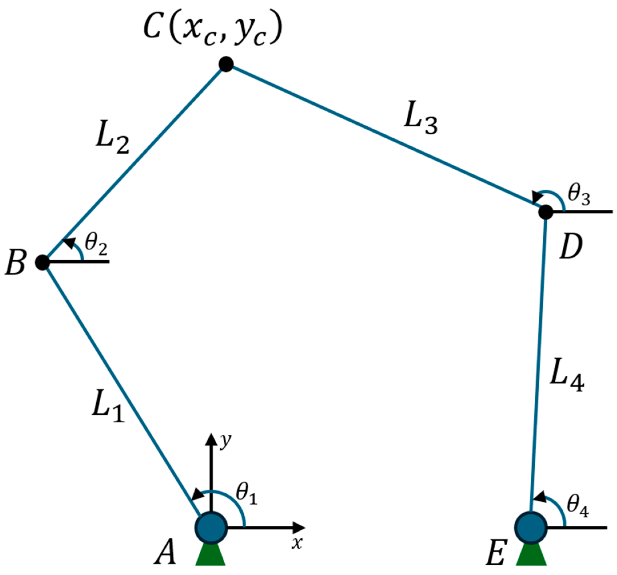
Figure 1.
As depicted in
Figure 1, the manipulator configuration consists of two fixed points,
and
:
Point is located at the origin .
Point is displaced along the x-axis at position ().
The links , , , and connect the joints at points , , , , and , where each joint has a specific angle: at ; at ; at ; and at . The positions of points and were derived using trigonometric relationships of the link lengths and input angles.
The position of points B and D can be found from an analysis of the configuration shown in
Figure 1. Given the fixed base at
, the coordinates of point
and D are as follows:
To determine the position of point
, which lies at the intersection of links
and
, the following conditions must be satisfied:
Substituting Equations (1) and (2) in Equation (5), we obtain the following:
To determine the position of
, subtracting Equation (8) from Equation (10), to eliminate
and
, and solving for
in terms of
, Equation (12) is obtained:
where
Substituting Equation (12) into Equation (7),
Simplifying to obtain a quadratic equation,
where
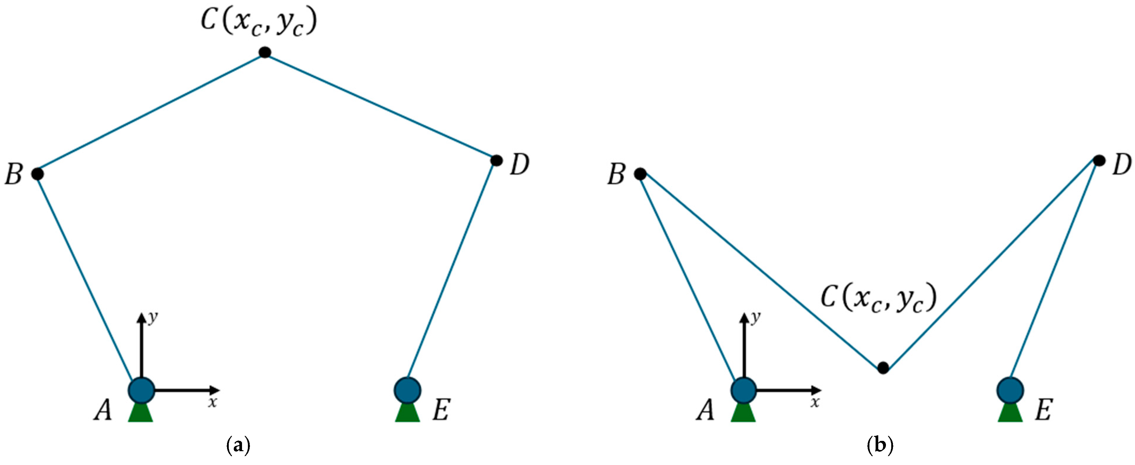
The parameter
yields two possible solutions [
11] corresponding to two assembly modes (
Figure 2):
In this study, the upper configuration was used.
Once
and
are known, the angles
and
are calculated as follows:
2.3. Inverse Kinematic Model
Inverse kinematics focuses on determining the angles of the robot’s joints that correspond to a desired position and orientation of the end-effector. This is essential for controlling the robot’s motion along a predefined trajectory. Specifically, the objective is to calculate the input angles
and
for the actuators when the coordinates of point
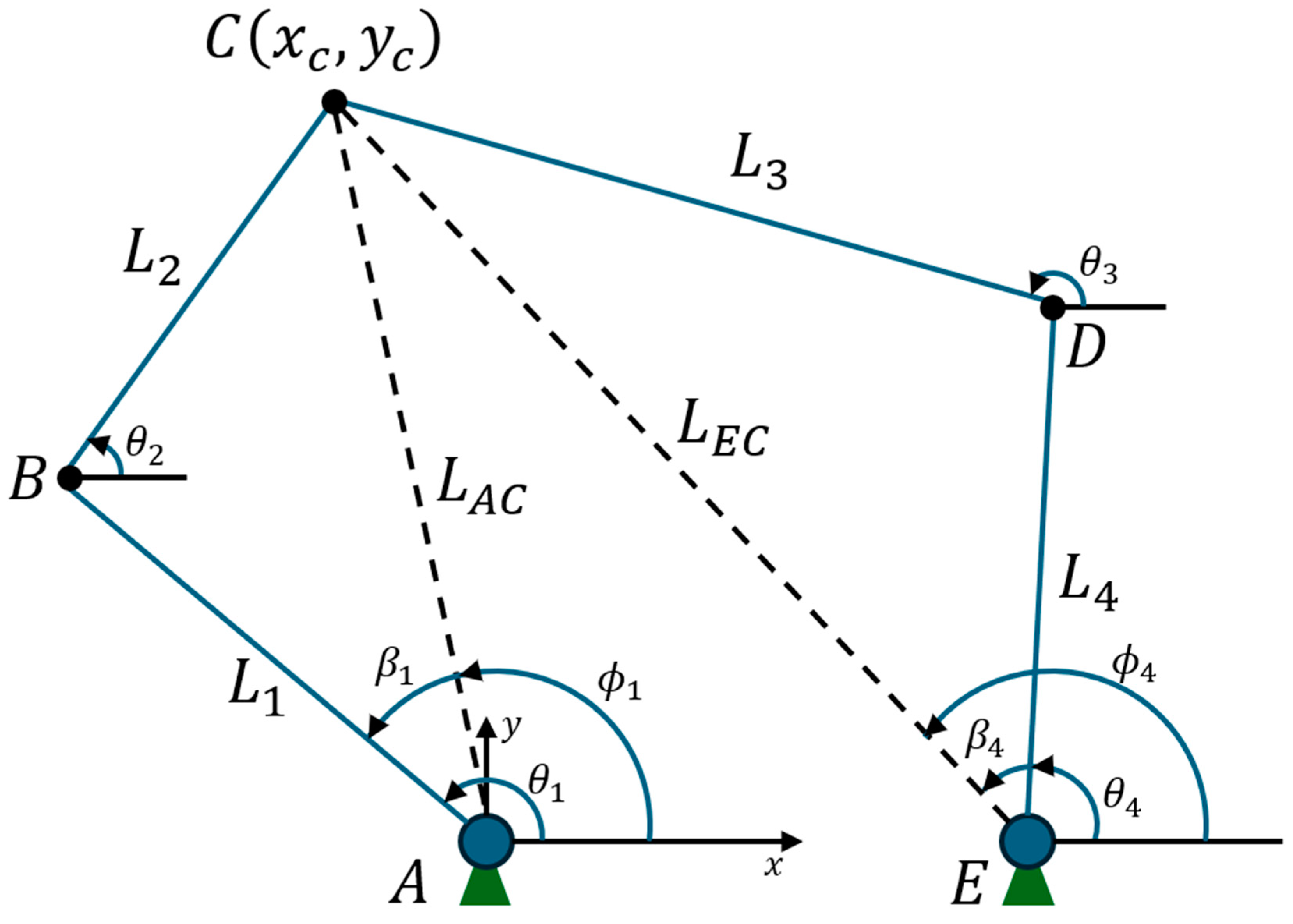
are known. This analysis serves as the foundation for precise trajectory control of the robot’s tool. Below, in
Figure 3, a geometric scheme for the study of inverse kinematics is shown.
From the triangle
and using the law of cosines,
From the vector relationships in triangle
,
Decomposing this equation,
From Equation (27), solving for
,
where
Applying the law of cosines to triangle
,
Similarly, applying the law of cosines to triangle
,
Using the results from Equations (33) and (35), the input angles
and
are calculated as follows:
From Equations (33)–(37), there are four possible solutions for the inverse kinematics problem, corresponding to different assembly modes of the manipulator (
Figure 4). These configurations are as follows:
“+ −” model: ,
“− −” model: ,
“+ +” model: ,
“− +” model: ,
These configurations are illustrated in
Figure 4, where each model represents a different working mode of the manipulator.
In this manner, the inverse kinematic model provides a framework for calculating the input angles and based on the desired position of the end-effector. By leveraging geometric constraints and trigonometric relationships, this study ensures precise control of the manipulator’s motion. This inverse kinematic analysis is critical for determining the joint movements required for the end-effector to follow a desired trajectory.
2.4. Workspace Analysis
The workspace of the 2-RRR planar parallel manipulator is defined as the set of points that the end-effector can reach when the joint angles and vary between and 2. This analysis excluded any interference between the manipulator’s links and ignores singularities. The workspace is bounded by surfaces that encompass all accessible points for the manipulator, whether it is fully extended or fully folded.
It is important to note that not all points within the workspace have the same level of accessibility. Points on the boundary of the workspace, which can only be reached with specific joint configurations, represent areas of minimum accessibility.
The workspace of the first kinematic chain was determined by two concentric circles:
The outer circle, with a radius of (
), represents the maximum reach when the manipulator is fully extended:
The inner circle, with a radius of (
), represents the minimum reach when the manipulator is fully folded:
These two circles define the workspace region of the first kinematic chain as the area between the circles and .
Similarly, the workspace of the second kinematic chain was defined by two concentric circles:
- 3.
The outer circle, centered at (
), with a radius of
:
- 4.
The inner circle, also centered at (
), with a radius of
:
The workspace region of the second kinematic chain is the area between the circles and .
When both kinematic chains are considered, the theoretical workspace of the 2-RRR manipulator is defined as the intersection of the workspace regions of the two chains. If the following condition holds,
and
. No intersection exists, meaning the manipulator has no workspace. If
and
, the workspace is reduced to a single point, located at the center of the line segment
. If the condition
,
and
is met, the theoretical workspace is a region that corresponds to the overlapping area of the two concentric circles, as illustrated in
Figure 5.
In real-world applications, the actual workspace may be smaller than the theoretical workspace due to physical constraints, such as interference between the manipulator’s links; singularities were induced by configurations where the manipulator loses degrees of freedom, and joint limits were caused by restrictions on the angles and .
2.5. Development of the 3D Model
A 3D model of the 2RRR planar parallel manipulator was developed using ROS/Gazebo, enabling motion analysis through simulations. These simulations evaluated several critical aspects of the manipulator’s functionality, including the following:
Trajectory Analysis: Ensuring smooth and accurate movement along predefined paths.
Workspace Evaluation: Determining the range of accessible points for the manipulator.
Joint Limitations: Assessing the mechanical constraints of the joints.
Interference Checks: Identifying potential collisions or obstructions between links.
The simulation results provided valuable insights into the manipulator’s reach and accuracy across various positions. They also helped identify areas for improvement, allowing adjustments to the design to enhance performance and ensure the manipulator meets operational requirements.
The initial virtual design model created in ROS/Gazebo is shown in
Figure 6. This setup allows for analyzing the movement, reach, and response of the system under different trajectory profiles.
At this stage of this study, no specific methodology was implemented for directly capturing the laser position using vision sensors or tracking systems. Instead, a reference trajectory was designed using SolidWorks 2024 generating multiple points to precisely define the ideal manipulator path. This trajectory was used as a basis for evaluating the behavior of the digital twin in comparison to the physical execution of the manipulator, facilitating the analysis and comparison of results. However, we recognize that integrating visual servo-control techniques, such as Eye-to-Hand systems, could provide real-time position feedback using a vision sensor. This improvement would allow for direct and more accurate acquisition of the trajectory, minimizing errors and ensuring greater correlation between the ideal trajectory generated in the virtual environment and the trajectory executed by the physical system. Given these potential advantages, this integration represents a key area for future research to enhance trajectory tracking accuracy and system adaptability.
The physical implementation of the manipulator, based on the virtual design, was successfully constructed. The top view of the fabricated 2RRR manipulator is shown in
Figure 7. This configuration allows for real-time trajectory execution and feedback within the digital twin framework.
2.6. Control Kinematics
The control kinematics of the 2RRR planar parallel manipulator involve defining a desired trajectory in the XY plane and using inverse kinematics to calculate the joint angles and required for the end-effector to follow this path. The process begins by computing the angles for each trajectory point and adjusting them iteratively to minimize the error between the desired and current positions, with the process concluding when the measured position matches the desired position within an acceptable margin. A proposed control algorithm employed inverse kinematic equations for real-time trajectory tracking, continuously adjusting joint angles to account for external factors such as load variations and joint friction. Simulations conducted with linear and curved trajectories evaluated the algorithm’s precision and stability, demonstrating its effectiveness in maintaining accuracy and consistent motion under varying conditions.
2.6.1. Human–Machine Interface
The development in MATLAB included the creation of an interface that facilitates communication between the virtual model and the physical prototype of the manipulator. This interface allows real-time monitoring and extraction of kinematic data, ensuring that the operator can observe and analyze the system’s behavior in real time.
The interface provides bidirectional communication, allowing both the sending of commands to the manipulator and the reception of data from it. Additionally, it includes analysis tools to compare the simulated data with those obtained from the real system. This ensures the integration of the digital twin with the physical system, enabling adjustments and improvements in the manipulator’s control based on accurate and up-to-date data.
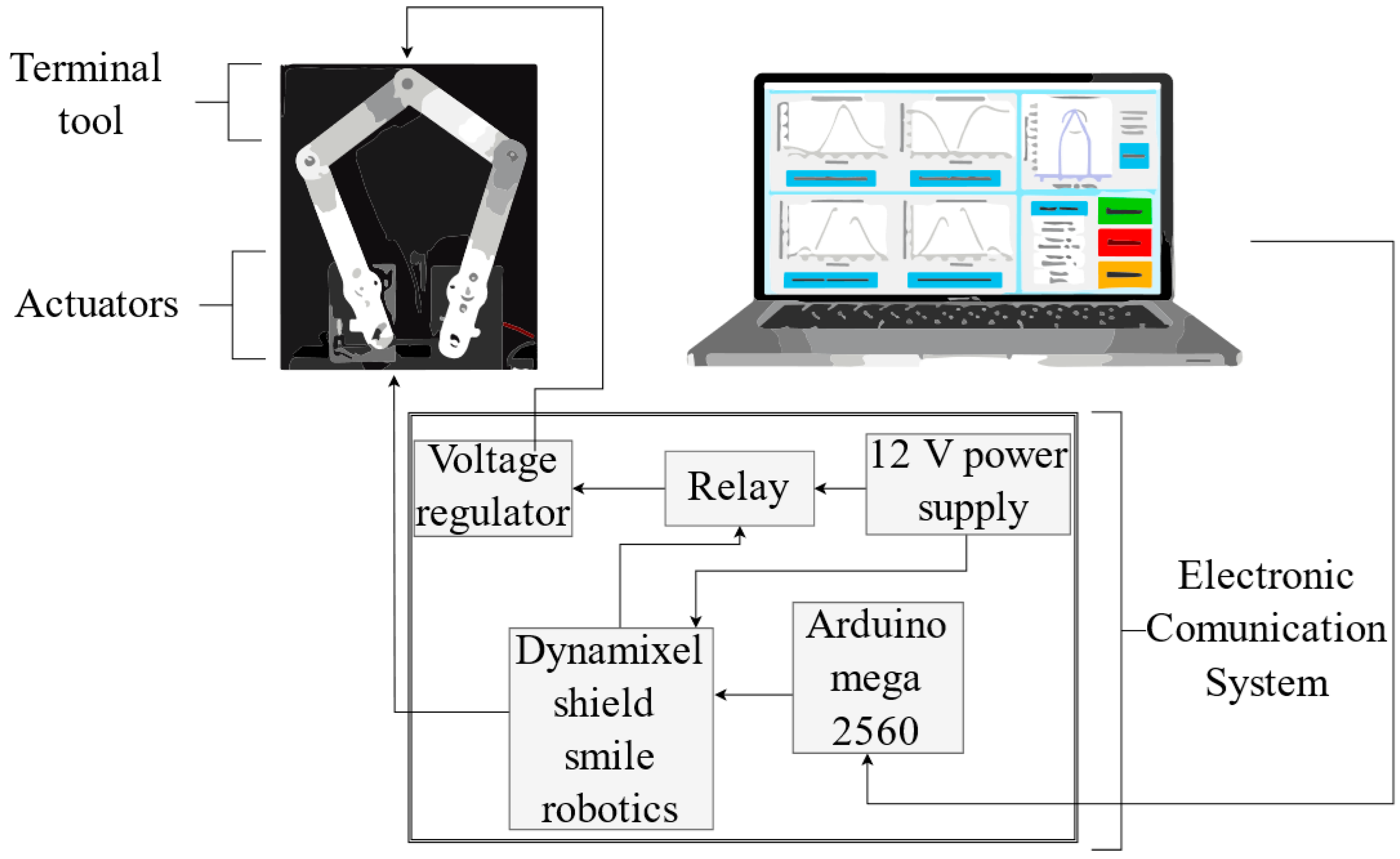
2.6.2. Electronic Communication System
The electronic communication system of the 2RRR manipulator comprises an ATMEGA2560 microcontroller (Arduino, Turin, Italy) and Dynamixel MX64 servomotors (Robotis, California, EEUU), interfaced through a Smile Robotics Dynamixel Shield. The system also includes a power supply, a voltage regulator, and a relay for the end effector.
Figure 8 shows the software–hardware communication flow and illustrates the interaction between the virtual environment, the microcontroller, and the hardware components of the manipulator. The MATLAB environment generates trajectory and control commands, which were transferred to the Arduino MEGA 2560 microcontroller. This microcontroller is responsible for executing kinematic calculations, controlling motor movements, and managing system operations. Additionally, the Dynamixel motors provided real-time feedback on angular positions, which were sent back to MATLAB to determine the manipulator’s final position using the kinematic model. The communication loop allows synchronized execution of trajectories with the physical prototype.
The microcontroller utilizes a switch-case algorithm to decode and execute received instructions. To prevent trajectory execution from being interrupted by the reception of new parameters, the inverse kinematic data vectors were pre-stored in the microcontroller.
During the development of the digital twin, trajectories were simulated in the virtual model to validate its ability to reach desired points without encountering singular configurations. The simulations considered the physical and electronic constraints of the actuators and control boards, resulting in a motion-position relationship engine. Displacement and angular velocity data obtained during simulations were exported in CSV format and transmitted to the HMI, which served as input for the microcontroller to execute the trajectory instructions.
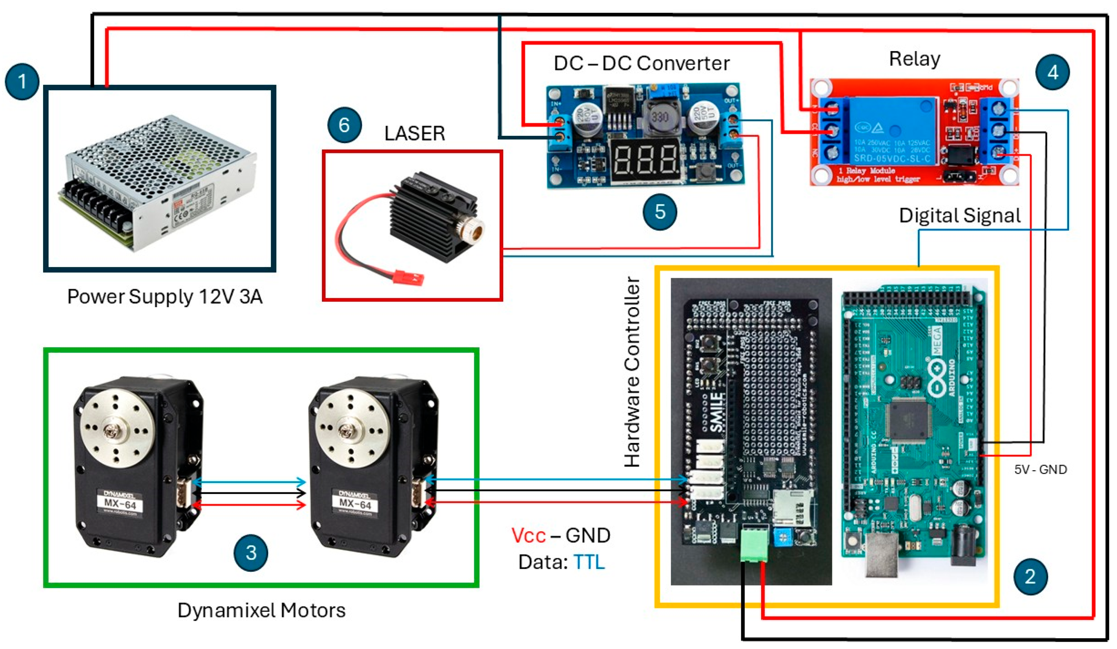
Figure 9 shows the configuration and operation diagram of the manipulator. The system was powered by a 12V power supply (1). The Arduino MEGA 2560 and Dynamixel Shield (2) managed the manipulator’s movements by controlling the Dynamixel MX-64 motors (3). A relay module (4) activated and deactivated the DC-DC LM2596 Step-Down converter (5), which regulated the power supplied to the laser system (6) for trajectory tracing. This configuration enables real-time control of the laser and actuators through coordinated software and hardware interaction.
The trajectory transmission and monitoring process, managed by Algorithm 1, ensures smooth execution of the manipulator’s motion:
| Algorithm 1: Trajectory transmission and monitoring |
| 1: | Initialization: |
| 2: | while samples sent < vector size do |
| 3: | | Read the microcontroller’s internal clock and store in variable |
| 4: | | Send movement instruction |
| 5: | | Take readings from the servomotors |
| 6: | | Send data to the interface |
| 7: | | Increment the sample sent counter by one |
| 8: | while sampling time do: |
| 9: | | | Read the microcontroller’s internal clock and store in |
| 10: | | | Wait for the sampling time |
| 11: | | end while | |
| 12: | end while |
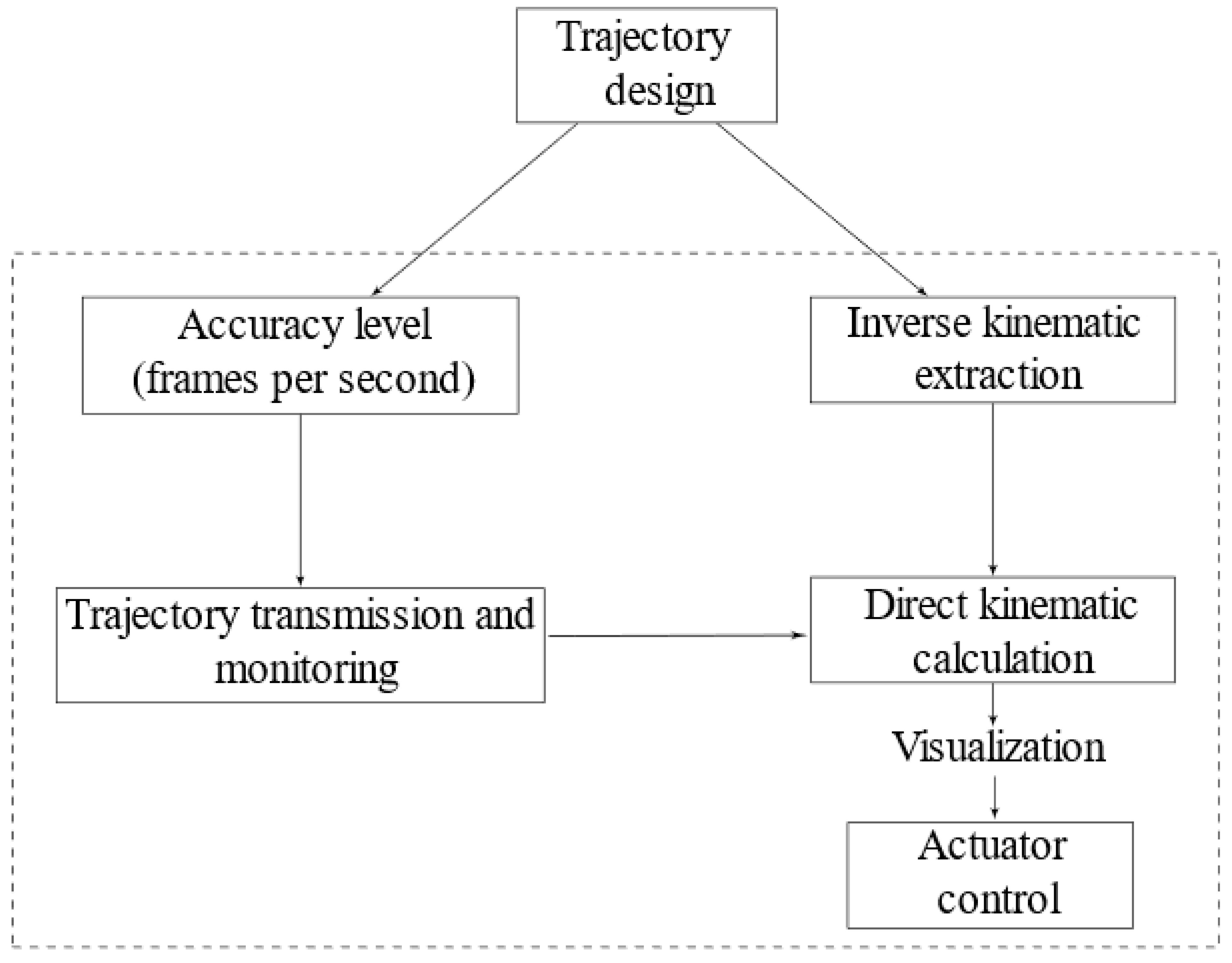
The kinematic control architecture (
Figure 10) integrated design and analysis tools to generate inverse kinematic solutions. This architecture enabled the calculation of joint coordinates required for the manipulator to follow trajectories defined in the virtual model. The trajectory data were transmitted from the virtual model to the microcontroller, ensuring precise control and synchronization between the digital twin and the physical prototype.
3. Results and Discussion
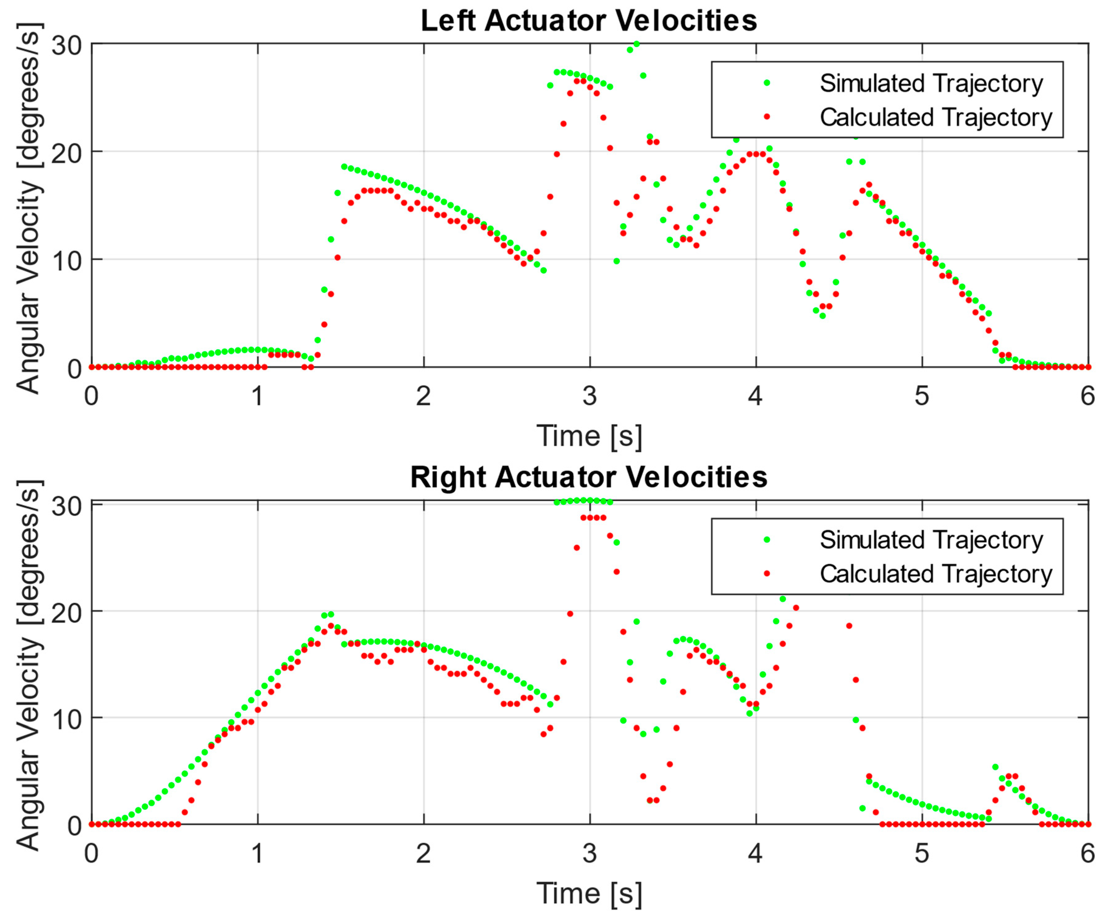
To validate the digital twin, the designed trajectory in the virtual model was compared with the one executed by the physical prototype using a knife-handle type trajectory. Inverse kinematic data and actuator readings were analyzed using trajectory graphs, position and angular velocity charts, and statistical tests.
The trajectory was set for a clockwise path of six seconds with a cycloidal profile, capturing results at 25 frames per second.
Figure 11 and
Figure 12 confirm that the positions and velocities are within permissible limits, and the sampling time ensures data transmission.
When analyzing two datasets to determine if one has greater variability than the other, an equality of variances test, a key statistical tool, was used. This test evaluates whether the variability within the datasets is similar, using a significance level of 5%, which implies operating with
confidence, a standard recommended by various authors for result validation. According to the results presented in
Table 1 and
Table 2, the obtained
p-values are greater than the
significance level, and the confidence interval includes the number one, specified in the null hypothesis of equal variances. A high
p-value suggests strong evidence in favor of not rejecting the null hypothesis, implying no statistically significant difference in the variability between the data of the trajectory designed in the virtual model and the data obtained from the trajectory executed by the physical prototype.
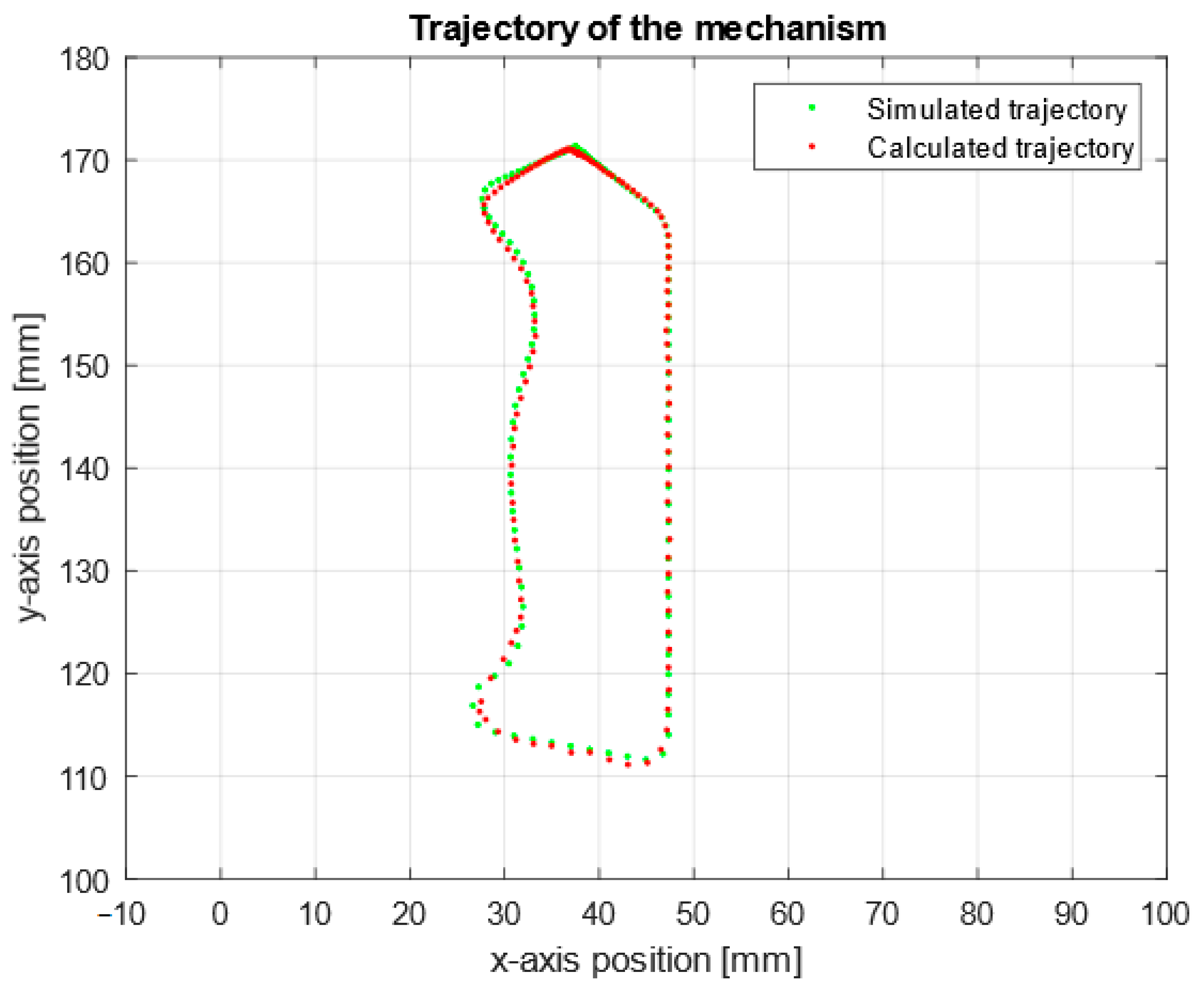
Figure 13 illustrates the trajectory traced by the prototype’s laser compared to the trajectory calculated by the virtual model. The high similarity between the two trajectories confirms that the digital twin accurately reproduces the behavior of the physical prototype. This validation highlights the system’s excellent performance, demonstrating precise alignment between the virtual and physical environments.
The integration of a digital twin with a physical prototype demonstrated its effectiveness as a tool for trajectory planning and control in robotic manipulators, aligning with the growing emphasis on digital twins in Industry 4.0. The comparison of trajectories in the virtual and physical environments revealed a high level of fidelity, as evidenced by statistical tests confirming the equivalence of variances and means for both actuator positions and velocities. This outcome underscores the reliability of the digital twin in replicating real-world behavior, validating its capability for precise synchronization and control. Furthermore, the use of cycloidal profiles in trajectory generation ensured smooth transitions, minimizing abrupt changes in angular velocity and reducing the mechanical strain on the manipulator’s joints. These findings highlight the importance of integrating digital twin technology into the development cycle, enabling iterative design and testing processes that optimize performance before deployment.
The proposed control architecture and human–machine interface enhanced the overall system performance by enabling real-time monitoring, bidirectional communication, and the seamless integration of simulated and experimental data. By leveraging the digital twin, trajectory errors were minimized through iterative adjustments, which were validated under various operational conditions, including different loads and friction levels. This adaptability demonstrates the robustness of the system for industrial applications, where dynamic environments demand precise and reliable control mechanisms. The application of statistical tools, such as variance and mean comparisons, not only provided quantitative validation of the system’s performance but also established a rigorous framework for future evaluations of robotic systems. These results contribute to the existing body of knowledge on digital twin technology, emphasizing its potential to improve the accuracy, efficiency, and adaptability of modern robotic systems.
To further validate the real-time adaptability of the digital twin, controlled external disturbances were introduced during the manipulator’s operation. These disturbances included applying small external forces to the joints to assess how the system compensates for mechanical perturbations and varying the manipulator’s loading conditions to analyze its response under different operational constraints. In both cases, the system successfully adjusted the control signals sent to the actuators, allowing the manipulator to correct deviations and maintain its planned trajectory within acceptable error margins. These findings confirm the system’s ability to dynamically respond to unforeseen interferences, beyond just compensating for mechanical inaccuracies or servo drive signal processing errors.
The developed digital twin presents high potential for implementation in industrial environments, particularly in tasks that require the precision and advanced control of parallel manipulators. To improve the accuracy and adaptability of the proposed system, it is feasible to propose the incorporation of computer vision-based methodologies that provide real-time feedback on the position of both the manipulator and its digital twin. In particular, implementing Eye-to-Hand visual servo control would enhance target localization, reducing execution errors and improving the correlation between the ideal trajectory generated in the virtual environment and the trajectory executed by the physical system. This integration would be especially valuable in automated manufacturing processes, where precision and stability in manipulator control are critical factors for performance.
Beyond trajectory optimization, the digital twin can also support quality control, deviation detection, and predictive maintenance by enabling the continuous real-time monitoring of the manipulator. Additionally, this system can serve as a training tool, allowing operators to safely simulate and test robotic operations without risks, thus facilitating the adoption of Industry 4.0 technologies and improving overall efficiency in production environments.
4. Conclusions
This study developed and validated a digital twin of the 2RRR planar parallel manipulator, integrating CAD software (SolidWorks 2024), real-time monitoring tools, and an interactive graphical interface for trajectory generation and system control. The digital twin allowed seamless communication with the physical prototype through a scalable electronic communication system that utilized microcontrollers, servomotors, and specialized algorithms. This integration enabled real-time trajectory execution, ensuring precision and adaptability in the manipulator’s operations.
The results of the statistical analysis confirmed a high level of concordance between the angular movements of the digital model and the physical prototype, despite minor differences. Hypothesis tests, conducted with a 95% confidence level, validated the statistical equivalence of position and velocity data between the virtual and physical systems. These findings underscore the reliability of the digital twin in replicating the behavior of the physical prototype. The observed differences in angular velocities were attributed to the dynamics of the system, including the limitations of the servomotors’ precision and potential calibration errors, which may affect the exact reproduction of trajectories.
The developed system demonstrates the potential of digital twin technology for improving the design, control, and validation of robotic systems. By enabling iterative testing and real-time adjustments, the digital twin enhances efficiency, reduces mechanical strain, and facilitates the optimization of robotic trajectories under various conditions. This work contributes to the growing body of knowledge on digital twins in robotics and highlights their role as a reliable and effective tool for trajectory planning, system validation, and performance improvement in industrial applications.


 ,
, 


