Article

An Advanced Path Planning and UAV Relay System: Enhancing Connectivity in Rural Environments

by
Mostafa El Debeiki
1,
Saba Al-Rubaye
1,
Adolfo Perrusquía
1,*,
Christopher Conrad
1 and
Juan Alejandro Flores-Campos
2
1
School of Aerospace, Transport and Manufacturing, Cranfield University, College Road, Bedford MK43 0AL, UK
2
Instituto Politécnico Nacional, Instituto Politécnico Nacional 2580, Mexico City 07340, Mexico
*
Author to whom correspondence should be addressed.
Future Internet 2024, 16(3), 89; https://doi.org/10.3390/fi16030089
Submission received: 18 February 2024 / Revised: 28 February 2024 / Accepted: 4 March 2024 / Published: 6 March 2024

Abstract

:
The use of unmanned aerial vehicles (UAVs) is increasing in transportation applications due to their high versatility and maneuverability in complex environments. Search and rescue is one of the most challenging applications of UAVs due to the non-homogeneous nature of the environmental and communication landscapes. In particular, mountainous areas pose difficulties due to the loss of connectivity caused by large valleys and the volumes of hazardous weather. In this paper, the connectivity issue in mountainous areas is addressed using a path planning algorithm for UAV relay. The approach is based on two main phases: (1) the detection of areas of interest where the connectivity signal is poor, and (2) an energy-aware and resilient path planning algorithm that maximizes the coverage links. The approach uses a viewshed analysis to identify areas of visibility between the areas of interest and the cell-towers. This allows the construction of a blockage map that prevents the UAV from passing through areas with no coverage, whilst maximizing the coverage area under energy constraints and hazardous weather. The proposed approach is validated under open-access datasets of mountainous zones, and the obtained results confirm the benefits of the proposed approach for communication networks in remote and challenging environments.

1. Introduction

The harsh terrain and hazardous weather in mountainous regions can disorient and cause injury to hikers or other individuals. Currently, such incidents are handled by calling the appropriate emergency services to receive aid and/or rescue. Autonomous vehicles and UAVs have also increased in popularity over the past decade [1] and have been adopted by mountain rescue (MR) teams to exploit their versatility and diverse sensors for such missions [2]. Mountainous areas, however, tend to have poor signal coverage, with little or no coverage in many zones [3]. This is particularly problematic when typical protocols rely on the victim or victims contacting the MR team and providing them with an approximate location.
Artificial intelligence (AI) methods [4] combined with modern drone technology have been used to improve services by (a) autonomously detecting areas that require the assistance of MR teams, and (b) enhancing the connectivity signal in low-coverage zones through UAV relay systems. Nonetheless, the irregular elevation in mountainous terrain often causes loss of coverage between the victim and the cell-tower. Furthermore, UAVs have limited flight time and often cannot completely explore large and complex mountainous areas. Moreover, effective handovers remain a considerable challenge. A challenge thereby arises to optimally position a UAV relay to maintain direct line of sight with both the victim and the cell-tower.
This paper aims to predict potential locations where relay intervention is required, whilst planning a path for UAV relays to establish contact with MR resources and relay cell-towers. This is accomplished using a viewshed map that identifies the visibility between points of interest and uses it to feed an  A  algorithm for path planning and signal coverage optimization with energy awareness. The benefits of this approach are demonstrated using open-access datasets of mountainous regions.

1.1. Previous Studies

Several studies have investigated risk prioritization to determine areas of higher risk to people. In [5], fuzzy logic was used to create a risk/occupancy map and determine emergency zones in terms of visiting frequencies, wildlife, and environmental conditions. Such an approach, however, requires expert knowledge of the area and other data that are often not available. Deterministic propagation models [6] have been further used to identify areas that require assistance due to a lack of signal connectivity [7]. Here, factors such as rain, vegetation, and interference caused by nearby channels or solar radiation attenuate and distort the signal [8]. The Longley–Rice propagation model was combined with digital elevation terrain data to calculate the pathloss along the trajectory of mobile network nodes in mountains [9]. The study concluded that optimally positioned relays are required to ensure communication between nodes. Similarly, ref. [10] proposed terrain-based channel modeling for a fixed height static UAV relay to generate propagation pathloss and blockage maps for LTE using terrain and LIDAR data of rural areas. Terrain elevations and obstacles, however, were not considered in this study, reducing its applicability to mountainous areas.
Relay path planning has been studied to overcome the challenges of a static relay. Biologically inspired search-based algorithms have shown better performance when faced with high uncertainty in unknown dynamic environments, but are too slow for real-time applications and can converge at local minima [11,12]. Other approaches adopt statistical learning methods to optimize the charging [13] and energy consumption [14] of UAVs. These studies, however, do not consider the effect of wind, which becomes a significant factor in mountainous regions. Probabilistic channel models have also been extensively used for UAV relay paths [15,16,17], using either iterative convex optimization [18] or non-convex optimization techniques [19,20]. Moreover, channel models have been combined with reinforcement learning for path optimization and relay deployment between UAVs and cell-towers in a post-disaster scenario [21]. This method, however, lacks robustness in the face of obstacles and adverse weather conditions [22]. Channel models, in fact, have been criticized for not adequately considering environmental factors and conditions [23].
An autonomous dynamic UAV relay algorithm was proposed in [24] to adjust UAV movement in parallel to that of the mobile ground nodes. A similar approach was proposed using the  A  algorithm for communication and energy-aware path planning in [25,26]. These approaches, however, use simplistic terrain models that cannot adequately cover the complex topology of mountains in the UAV–environment interaction. This is a common challenge in current air-to-ground channel modeling [27,28,29]. Furthermore, ref. [30] concludes that an open issue in path optimization is to design a trajectory that prevents the UAV from crossing areas with no cellular coverage. This is particularly relevant in mountain scenarios with many areas of limited or no coverage. To address this concern, ref. [31] proposed a colony optimization algorithm to plan the shortest safe path in a dense mountainous area. Nonetheless, mountains were still modeled as simple regular objects. Similarly, ref. [32] optimized the shortest flight path by considering the distances between the UAV and relevant obstacles using unrealistic terrain models that do not match the complexity of real-world data. Conversely, ref. [33] employed a viewshed algorithm to generate UAV paths that maximize the visual coverage of hidden areas in a target territory.

1.2. Contributions

In view of the existing work discussed in the previous section, this paper reports a path planning and UAV relay system for rural environments. The main contributions of this work are as follows:
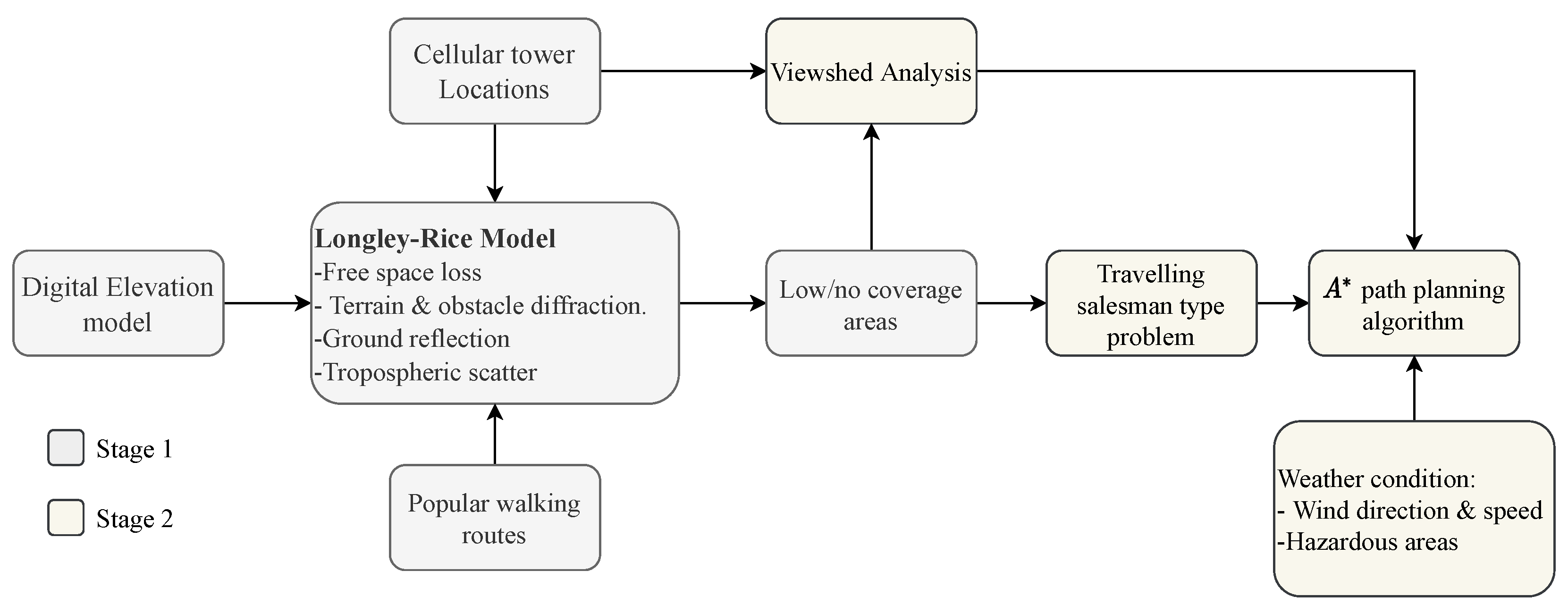
  • A two-stage framework is proposed to allow coverage to areas with poor signal propagation by relaying signals from the available cell-towers.
  • A viewshed analysis was conducted to determine the mutual visibility region between points of interest and cell-towers.
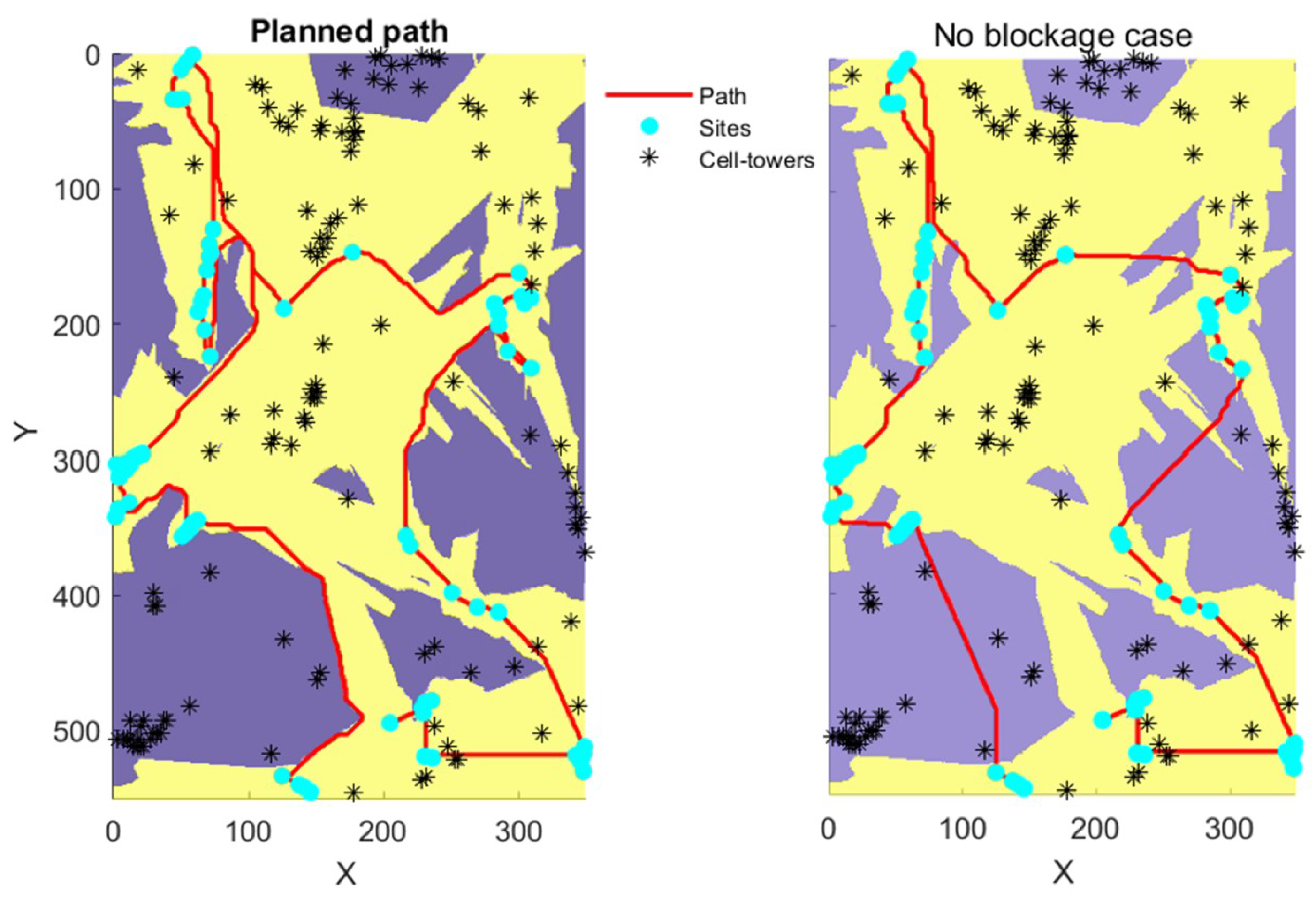
  • A blockage map was created to prevent the UAV from passing through no coverage areas.
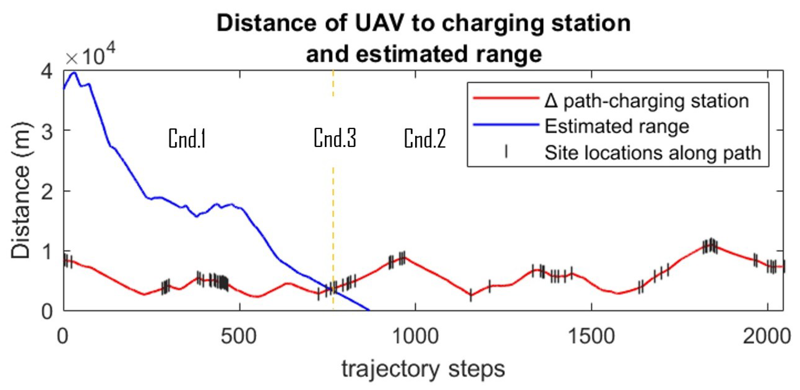
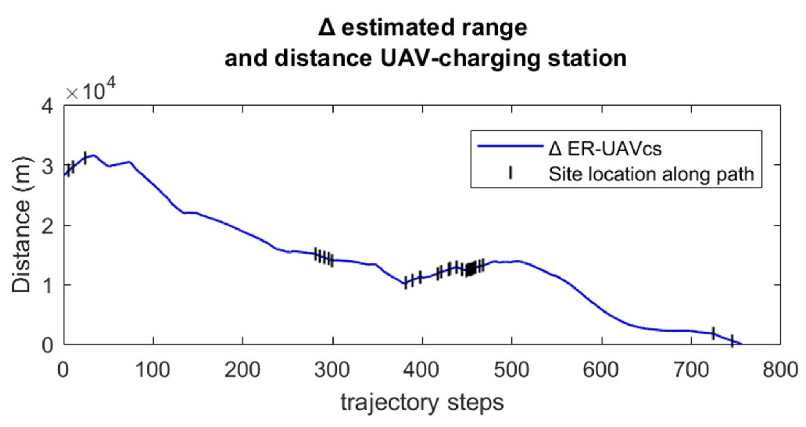
  • The approach enables the UAV to determine the optimal time to head back towards the charging station.

2. Materials and Methods

A two-stage framework is proposed to address path planning optimization for UAV relay positioning, as depicted in Figure 1. The first stage aims to predict the likely locations where MR services are required to aid victims experiencing low mobile coverage. Notably, the location of nearby cellular towers and a digital representation of the terrain elevation are combined to model the coverage of relevant cell-towers. This is achieved by computing the signal propagation pathloss at each point along popular walking and hiking routes using the Longley–Rice propagation model. Areas of the tracks with undesirable coverage are subsequently identified as areas of interest.
The second stage focuses on optimally planning the UAV relay path to pass through the areas of interest. Firstly, the traveling salesman problem is solved using the areas of interest to determine the optimal visiting order that minimizes the total path distance. A visibility analysis is then conducted to identify visible points from a specific altitude and prevent the relay from passing through areas with no coverage. Weather conditions are also taken into account to (a) determine hazardous areas, (b) modulate the throttle based on air speed, and (c) boost the autonomy of the UAV through energy awareness.

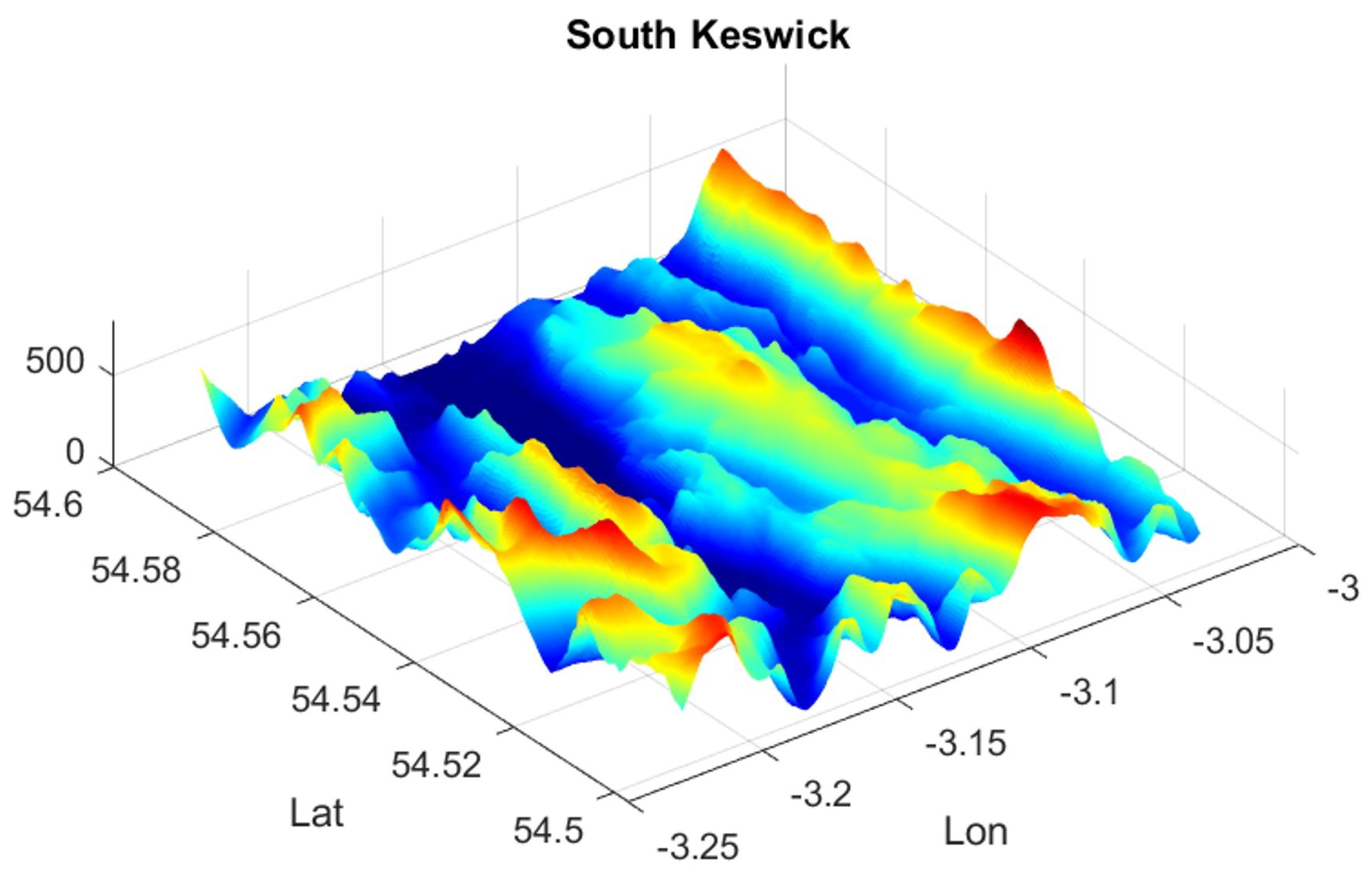
2.1. Datasets: Terrain, Cell-Tower Locations, and Popular Walking Routes

The proposed framework was evaluated through a case study of the Lake District national park, focusing on Keswick as a region with high mountainous peaks and frequent emergency callouts. Elevation data were obtained from the open-access Shuttle Radar Topography Mission (SRTM) 1-arc global dataset [34], which has a 30 m resolution (at sea-level at the Equator). Each data file covers a one-degree-of-latitude by one-degree-of-longitude tile of Earth’s surface. The dataset is composed of the following formats:
  • Digital terrain elevation data, which involve a standard mapping format that contains a matrix of vertical elevation values spaced at regular horizontal intervals measured in geographic latitude and longitude units.
  • Band-interleaved-by-line, which is a binary raster format with an accompanying header file which describes the layout and formatting of the file.
  • Georeferenced tagged image file format, which is a TIFF file with embedded geographic information.
These data were first imported as geographic raster files to obtain the data grids and their corresponding spatial information, including limits, grid spacing, and coordinate references. The elevation data were then interpolated to achieve a finer resolution, yielding the result shown in Figure 2.
The cellular tower locations and popular cycling routes in Keswick were obtained from GPS data available in the Opencellid and GPS Cycle and Walking Routes open-access databases [35]. Some cellular towers, however, had an approximate location estimated from signal measurements or provided by the carrier company.

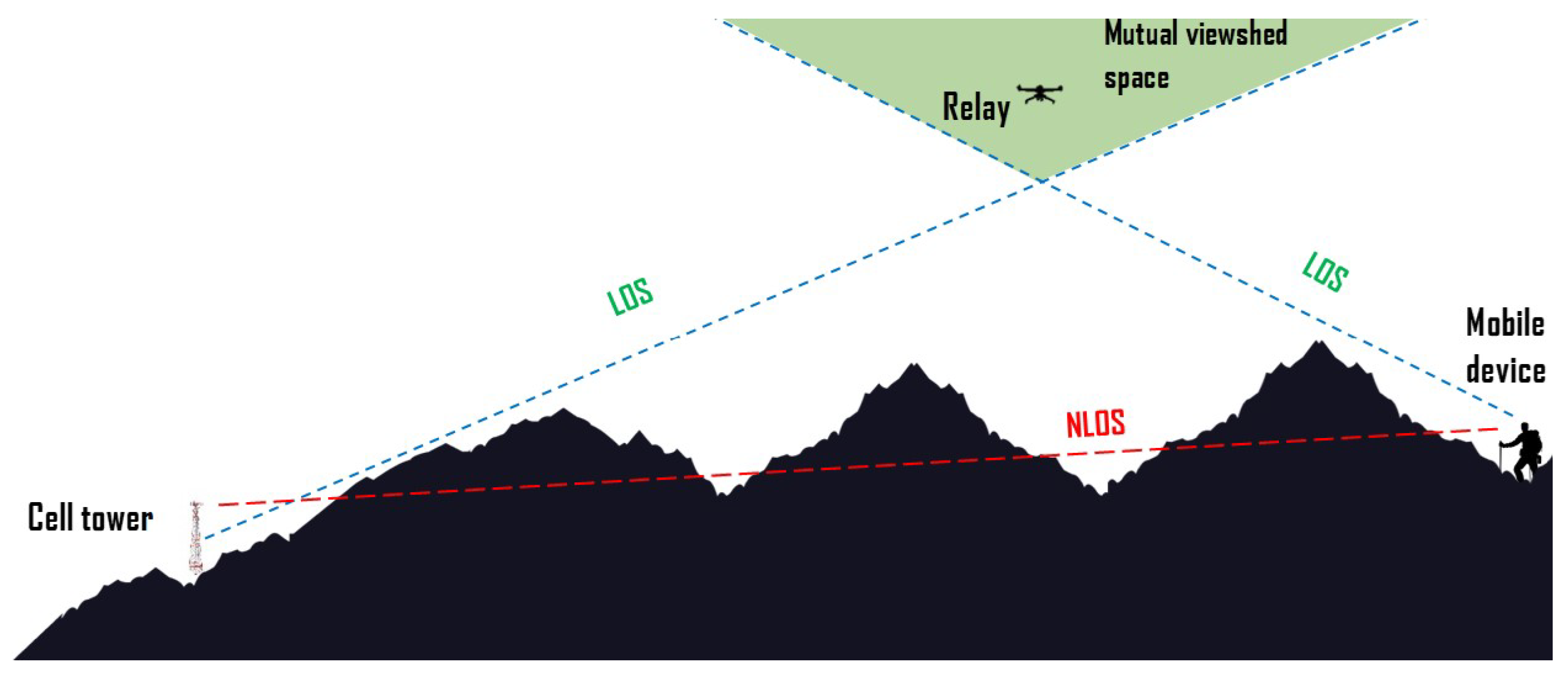
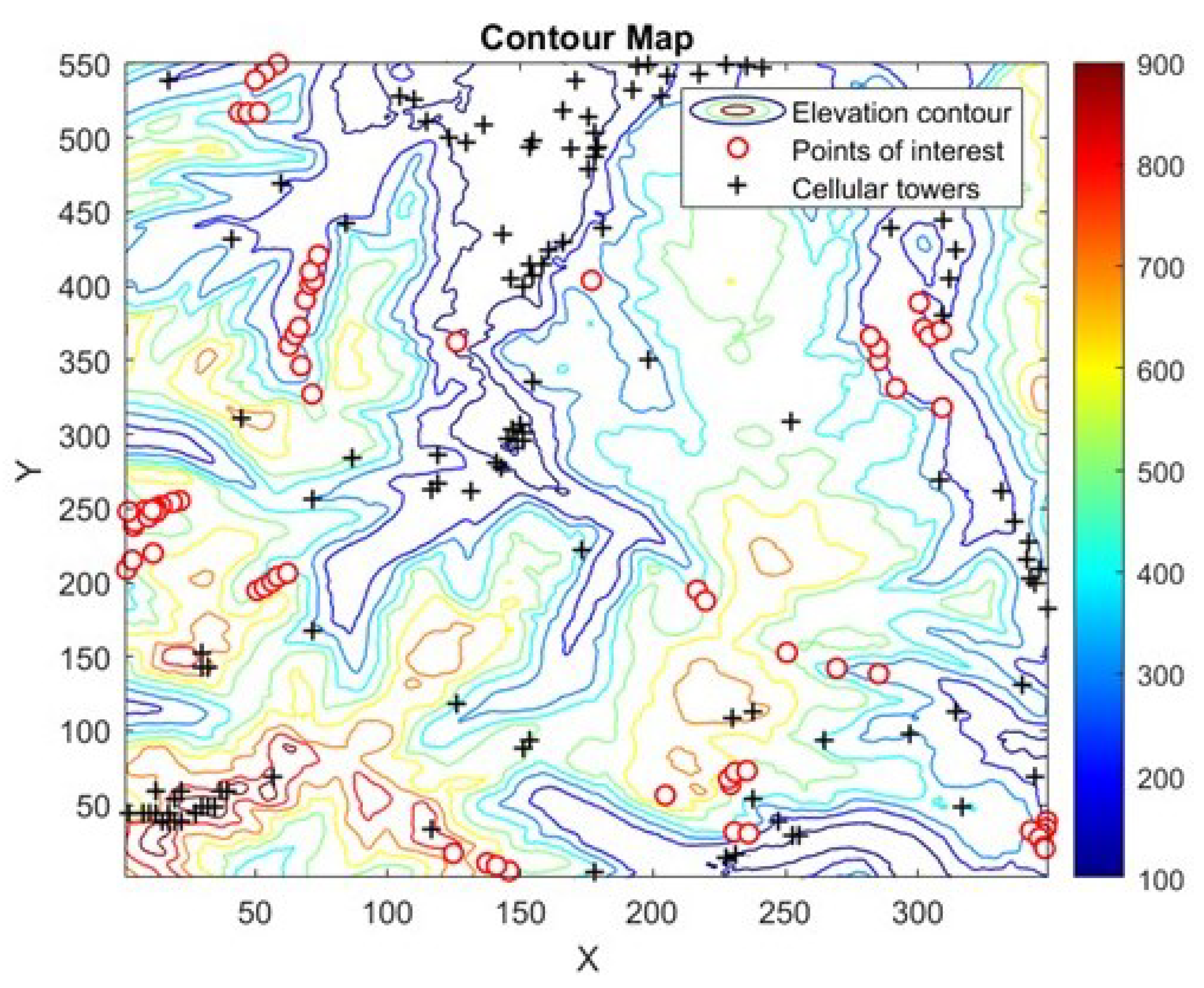
2.2. Coverage Analysis

Signal propagation was modeled by considering the location of each cellular tower as the transmitter site, and that of each track waypoint as the receiver. For all towers, the transmitting frequency was assumed to be 2.5 GHz, with a transmission power of 10 W and an antenna height of 10 m. Similarly, a receiving antenna with a sensitivity of −100 dBm and a height of 1.5 m was assumed to approximate the mobile phones of injured victims.
The Longley–Rice irregular terrain model was used to estimate the signal pathloss, since it considers the terrain profile between the transmitters and receivers. Specifically, the signal strength is calculated from the lowest pathloss value across all receivers using
P r x = P t x pathloss ,
where  P r x  and  P t x  define the signal power of the receiver and transmitter, respectively. The link margin for each receiver is subsequently obtained using
R x margin = R x sensitivity P r x .
A receiver with a negative link margin corresponds to a weak signal that cannot be detected. Consequently, all receivers with a negative link margin are deemed to fall outside the coverage area of a cell-tower and define the required points of interest.

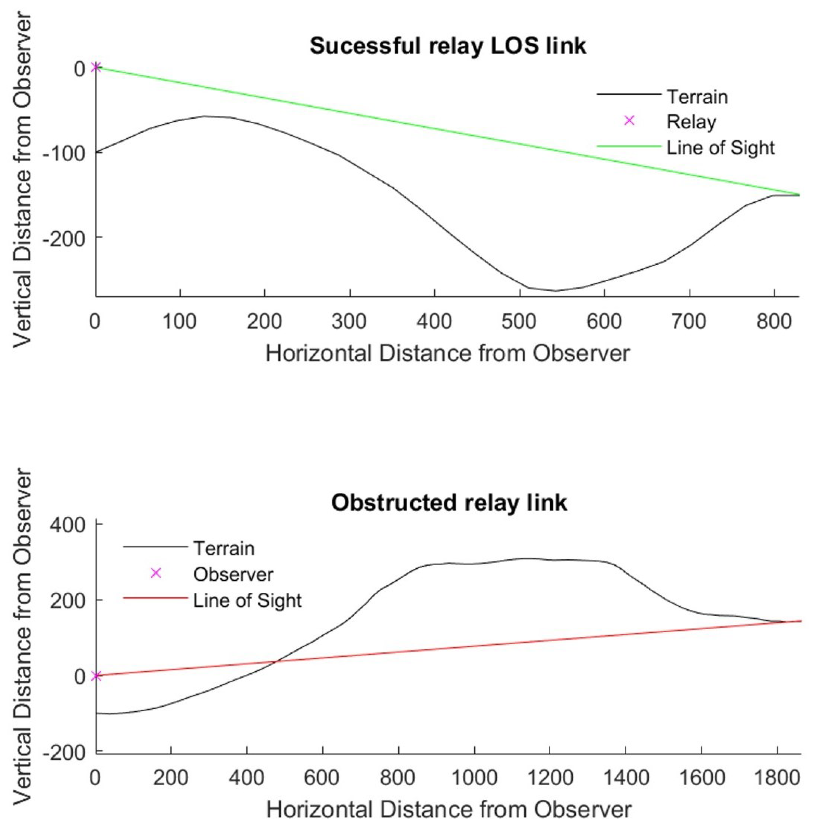
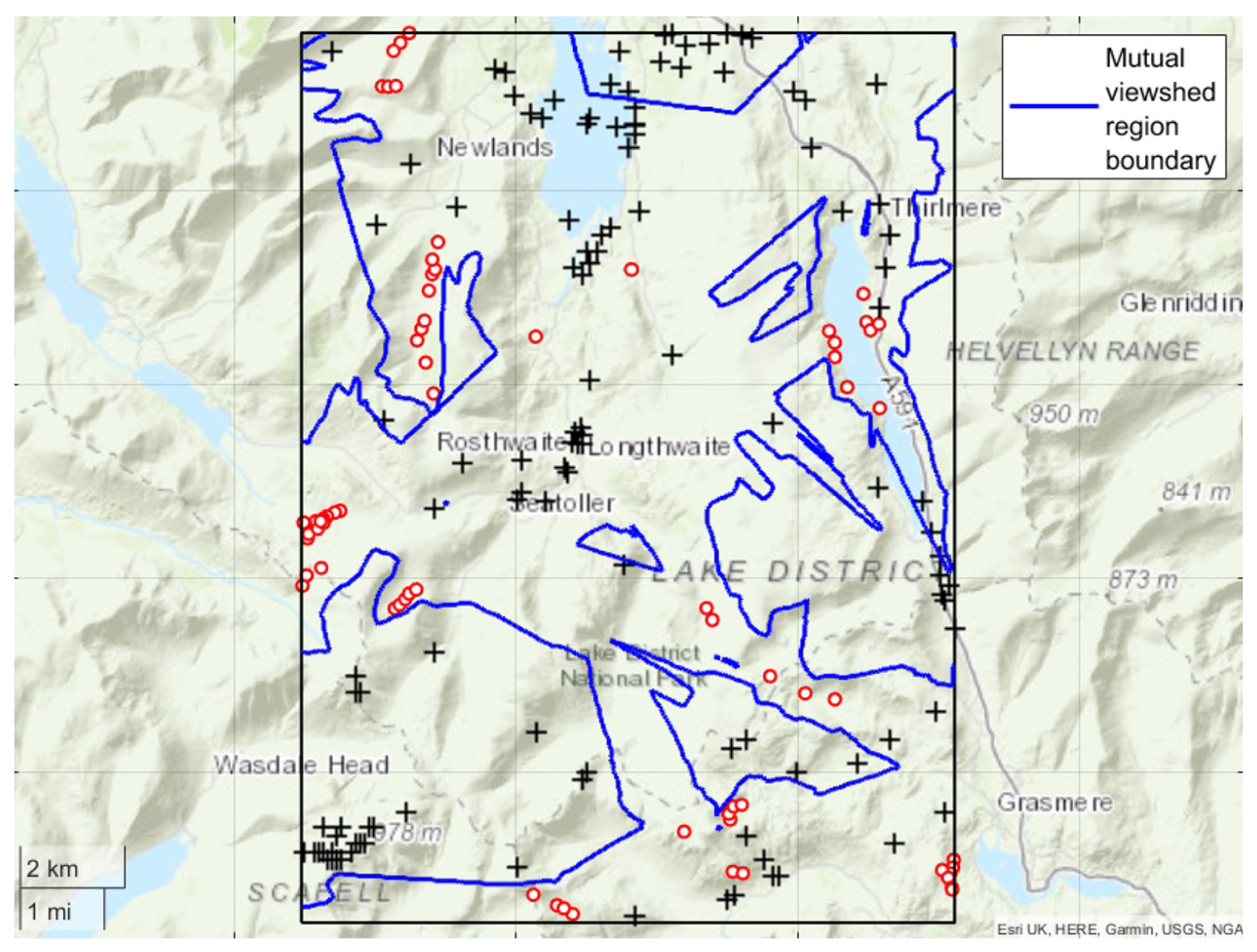
2.3. Viewshed Analysis

A viewshed is defined as the ensemble of points or areas that are visible from a certain location. A viewshed analysis is thereby crucial in UAV relay planning to determine the regions where a UAV relay simultaneously maintains direct line of sight to the areas of interest and cell-towers (see Figure 3).
The results of the viewshed analysis are represented as binary raster data through a visibility/blockage map having the same dimensions as the geographic region under consideration. Specifically, a 1 refers to a point within the mutual viewshed, while a 0 refers to a point outside the mutual viewshed. For a successful UAV relay, a simultaneous link between the transmitter and receiver is required, where successful communication is assumed to be equivalent to a line-of-sight connection. Consequently, the blockage area at a specific UAV relay height above ground is defined as the ensemble of points where:
  • There is no line of sight between the transmitter and receiver;
  • Only the transmitter has line of sight;
  • Only the receiver has line of sight.

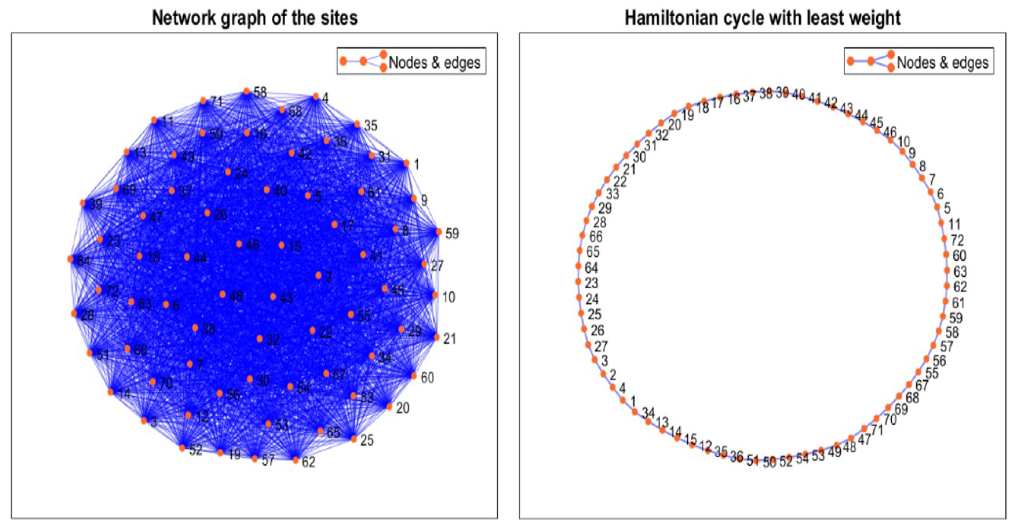
2.4. Traveling Salesman Problem

Sparsely distributed points of interest are obtained from the coverage analysis, which can be visited in any order. The traveling salesman problem is used to determine the optimal visiting order of each point of interest by minimizing the total distance, and consequently, the energy consumption. A weighted square adjacency matrix is first created, where the number of rows and columns are equal to the number of points of interest. The total Euclidean distance is subsequently defined as the cost metric to determine the optimal visiting sequence of the points of interest.

2.5. The A Search Algorithm

The optimal visiting sequence obtained from the traveling salesman problem optimization does not consider irregular terrain elevations. Furthermore, the UAV needs to fly at a constant height above ground level, such that some points cannot be reached using a simple straight line path. To deal with this issue, the  A  search algorithm was used to find the minimum cost path between the sequence of points of interest. Here, the goal of the  A  algorithm is to find the path that minimizes the following cost:
F c o s t i = g c o s t i + h c o s t i ,
where  g c o s t i  represents the accumulated travel cost between the current node and the previous nodes, and  h c o s t i  represents the heuristic cost, which is an estimation of the cost between the current and the goal nodes. The spatial resolution of the raster data grids was considered in the cost function of the  A  algorithm. In this case, the length and width of the Keswick region were divided by the number of rows and columns, respectively, of the raster grid to obtain the longitudinal and latitudinal grid resolutions. The final resolutions for longitude and latitude are  r e s l o n = 35.988  m and  r e s l a t = 30.922  m. The cost index used by the  A  algorithm is, therefore, given by
Cos t 2 1 = r e s l o n ( x 2 x 1 ) 2 + r e s l a t ( y 2 y 1 ) + ( z 2 z 1 ) 2 .
The data used by the  A  algorithm were stored in a two-layer map while the search was performed. The first layer contained the digital elevation model raster, whilst the second layer contained the binary occupancy map that prevents the UAV from entering blockage and hazardous weather areas.

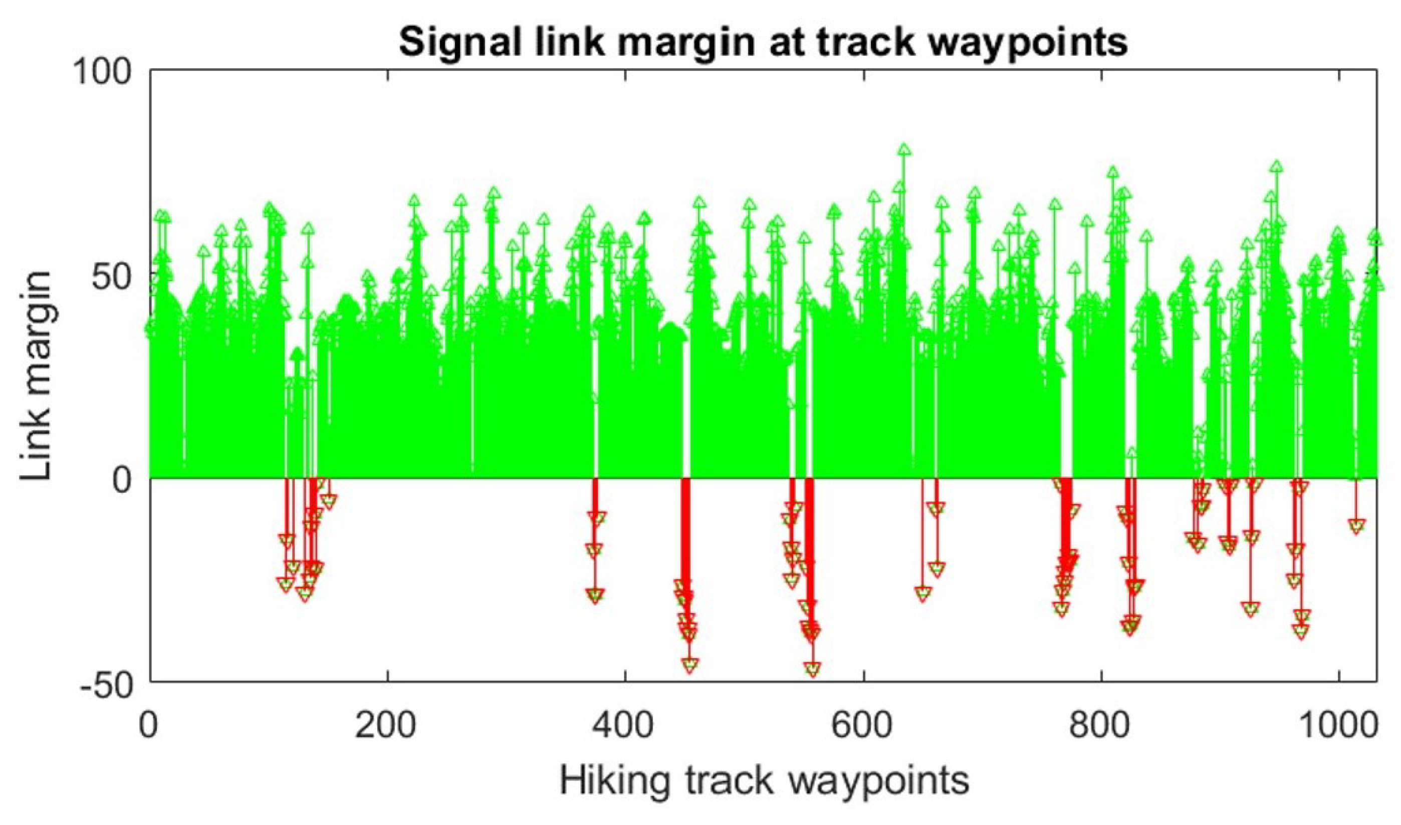
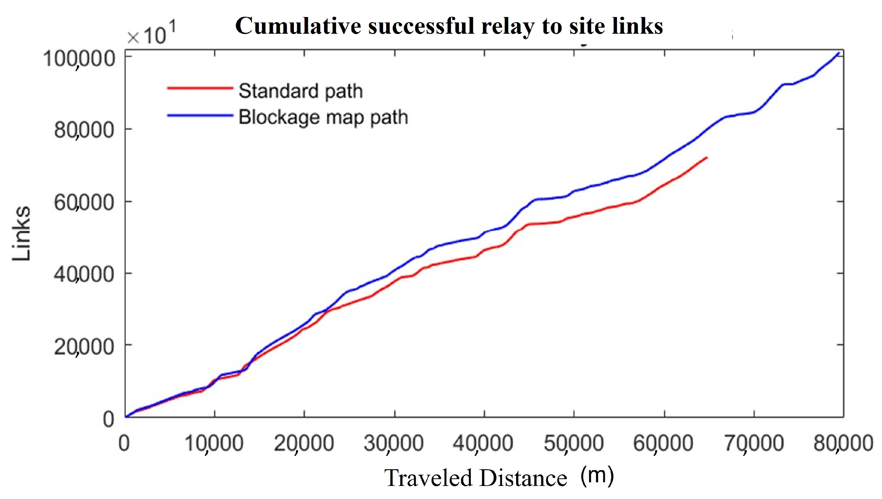
2.6. Performance Metric

To evaluate the performance of the proposed approach, the developed algorithm was compared against a non-blockage version of the path planner, where the UAV could freely fly to any area on the map. The total number of successful links divided by the distance traveled was used as the performance metric to evaluate the different paths. This assumed that a successful link was obtained between two points if direct line of sight was possible with both points. This is exemplified in Figure 4 for both successful and unsuccessful links.

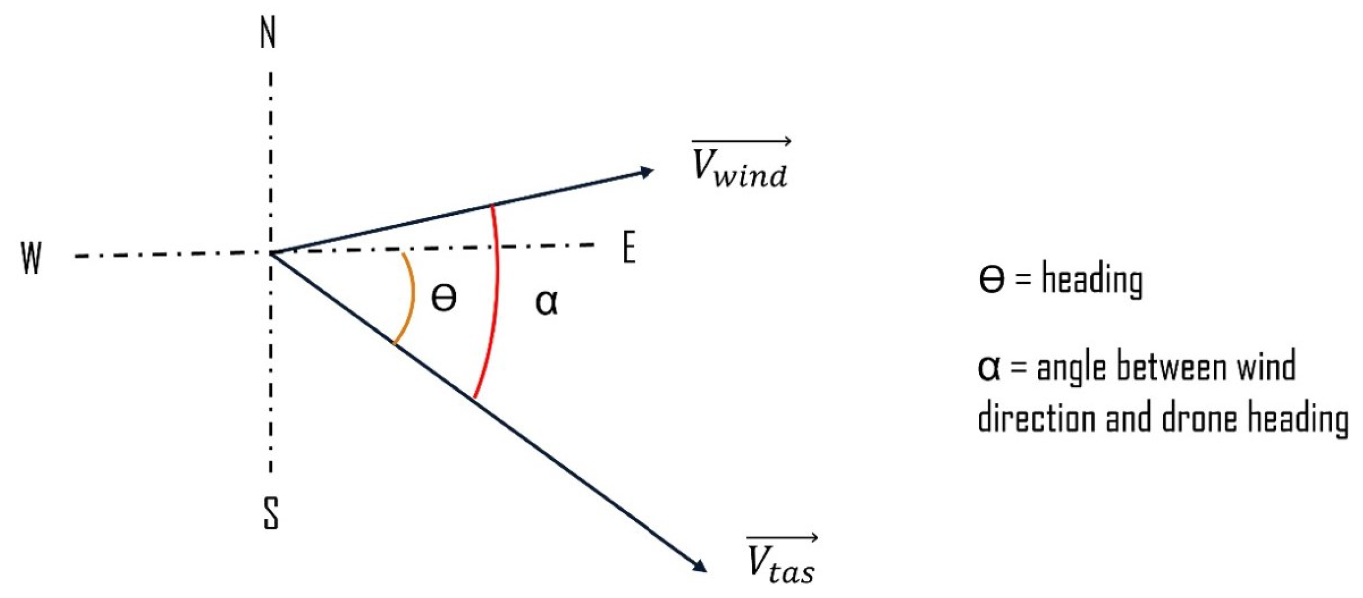
2.7. Energy Awareness and Wind Resilience

UAVs need to be resilient against adverse weather conditions, such as wind. When a UAV flies against the wind, it must increase its power to avoid time delays or instability issues. Conversely, when the UAV flies in the same direction as the wind, the consumed power can be decreased to save energy and cover longer distances before charging the battery. Battery consumption is, therefore, dependant on the wind, such that charging slots cannot be predefined due to the uncertainty of the wind speed and direction. Consequently, the UAV needs to autonomously decide when to stop the patrol mission and head towards a charging station.
This approach aims to maintain a constant ground speed throughout the trajectory by modulating the throttle, whilst avoiding deflection in the presence of wind. This causes the UAV to remain stationary when the UAV airspeed and wind speed are equal and opposite, satisfying the following relation:
Ground speed = True air speed + wind speed .
The UAV heading/angle and wind direction, however, change throughout mission execution, as depicted in Figure 5. The true air speed  V t a s  can, therefore, be determined using
V t a s = V G S V w i n d cos α .
At maximum speed, the UAV uses the maximum throttle, according to
V t a s m a x = Throttle m a x % .
Under the assumption that the throttle response is tuned such that  V t a s  grows linearly with  Throttle % , the required throttle percentage can be found using
Throttle % = V t a s V t a s m a x × 100 %
Combining (8) with (6) further suggests that
Throttle % = 100 ( V G S V w i n d cos α ) V t a s m a x .
From (9), it is noted that the  Throttle %  depends only on the wind velocity and its angle between the UAV heading, when assuming a constant ground speed. This value can, therefore, be used to estimate the energy consumption and determine when to return to a charging point. Under the assumption that the UAV is flying at maximum throttle, the motor consumes the maximum amount of current  I d r a w n m a x . Additionally, it is assumed that the current grows linearly with the throttle, such that
I d r a w n = Throttle % 100 × I d r a w n m a x .
Given a fixed ground speed, the total time traveled at step n is calculated from the distance traveled at each raster grid step as
t ( n ) = t ( n 1 ) + r e s l o n ( x ( n ) x ( n 1 ) ) 2 + r e s l a t ( y ( n ) y ( n 1 ) ) 2 + ( z ( n ) z ( n 1 ) ) 2 V G S .
The battery charge used can be subsequently calculated using
A h ( n ) = A h ( n 1 ) + I d r a w n ( n ) t ( n ) .
Consequently, the estimated remaining time at step n is found according to
Remaining flight time ( n ) = A h c a p a c i t y A h ( n ) I d r a w n ( n ) ,
where  A h c a p a c i t y  is the full battery charge capacity. Finally, the estimated remaining range is given by
Estimated range ( n ) = Remaining flight time ( n ) × V G S .
A random point from the Hamiltonian cycle output of the traveling sales problem is used as a charging station, such that the distance to this point is computed and denoted by  Δ path , station ( n ) . Three possible conditions thereby exist:
  • If  Estimated range ( n ) > Δ path , station ( n ) , it implies that the UAV has enough charge to reach the charge station.
  • If  Estimated range ( n ) < Δ path , station ( n ) , it implies that the UAV cannot reach the charge station.
  • If  Estimated range ( n ) = Δ path , station ( n ) , it implies that the UAV has the exact charge needed to reach the charge station.
Consequently, if the function  F ( n )  is defined as
F ( n ) = Estimated range ( n ) Δ path , station ( n ) ,
the UAV should go to the charging station after visiting the last point of interest while  F ( n ) > 0 . The function  F ( n )  should, therefore, be optimized, according to:
min n F ( n ) subject to : F ( n ) > 0 .

3. Results and Discussion

The proposed approach was tested to verify its effectiveness in maximizing the transmission coverage. The UAV used in this research is a long search and rescue/military/surveying drone.

3.1. Points of Interest

Figure 6 shows the results of coverage analysis, with the identified points of interest. A total of 1033 track waypoints were available in the Keswick area under consideration, with 72 points identified as points of interest without adequate coverage.
The points of interest were mainly located in deep valleys surrounded by high peaks or in zones with high elevation compared to the cellular towers nearby, as highlighted in Figure 7. This suggests that the terrain profile is an important factor to be considered for the signal pathloss calculation as it causes inconsistencies in the signal propagation. The terrain effectively acts as a barrier between two points, resulting in signal loss or degradation. Drones flying at high altitudes can be effectively employed as signal relays in such situations. However, the points of interest are spread out across a large area, confirming the need for an optimal path planning algorithm.

3.2. Path Planning

3.2.1. Viewshed Map

A path planning algorithm for UAV relay should not pass through areas with poor communication coverage. A viewshed analysis was, therefore, applied at a drone altitude of 100 m above ground level to determine the appropriate visibility region and avoid passing through areas with inadequate coverage, as shown in Figure 8. The viewshed map is used to construct a blockage map for the  A  algorithm to prevent the UAV from entering areas with no coverage.

3.2.2. Optimal Sequence

After the 72 points of interest were identified, the optimal visiting sequence was determined to minimize the total trip time. Here, the number of possible solutions is
C r n = n ! r ! ( n r ) ! = 2556 ,
where n is the number of points of interest and r represents the two actions of entering and exiting a point. The solution of the traveling salesman problem is used to determine an optimal visiting sequence known as the Hamiltonian cycle, as depicted in Figure 9.
Table 1 shows the distance between nodes of the traveling salesman problem solution. It was noted that the distance between some nodes is very high, suggesting that the terrain is irregular or obstructions are close. This further suggests that the optimal path between the nodes is not a simple straight line, an issue that was overcome using the  A  algorithm.

3.2.3. A Search

The  A  algorithm was employed for path planning along the points of interest. The proposed viewshed-based method was compared with the classical method based on raster data. The results are shown in Figure 10, where the planned path passes through the optimal sequence of points of interest. The classic map is constrained by the terrain and takes the shortest path between the points of interest without considering the blockage region. On the other hand, the proposed viewshed approach finds a path that stays in the visibility region, despite taking a longer route.
The average number of successful links per meter of flight was used as a metric to assess the efficiency of each method. Table 2 summarizes the comparison results, and shows that the blockage map path obtains 40.12% more links when compared to the classic path. This means that, on average, the blockage map links with 1.7 more points of interest per meter of flight, despite increasing the map path length by approximately 22.45%. Figure 11 further shows the cumulative links obtained in each case.

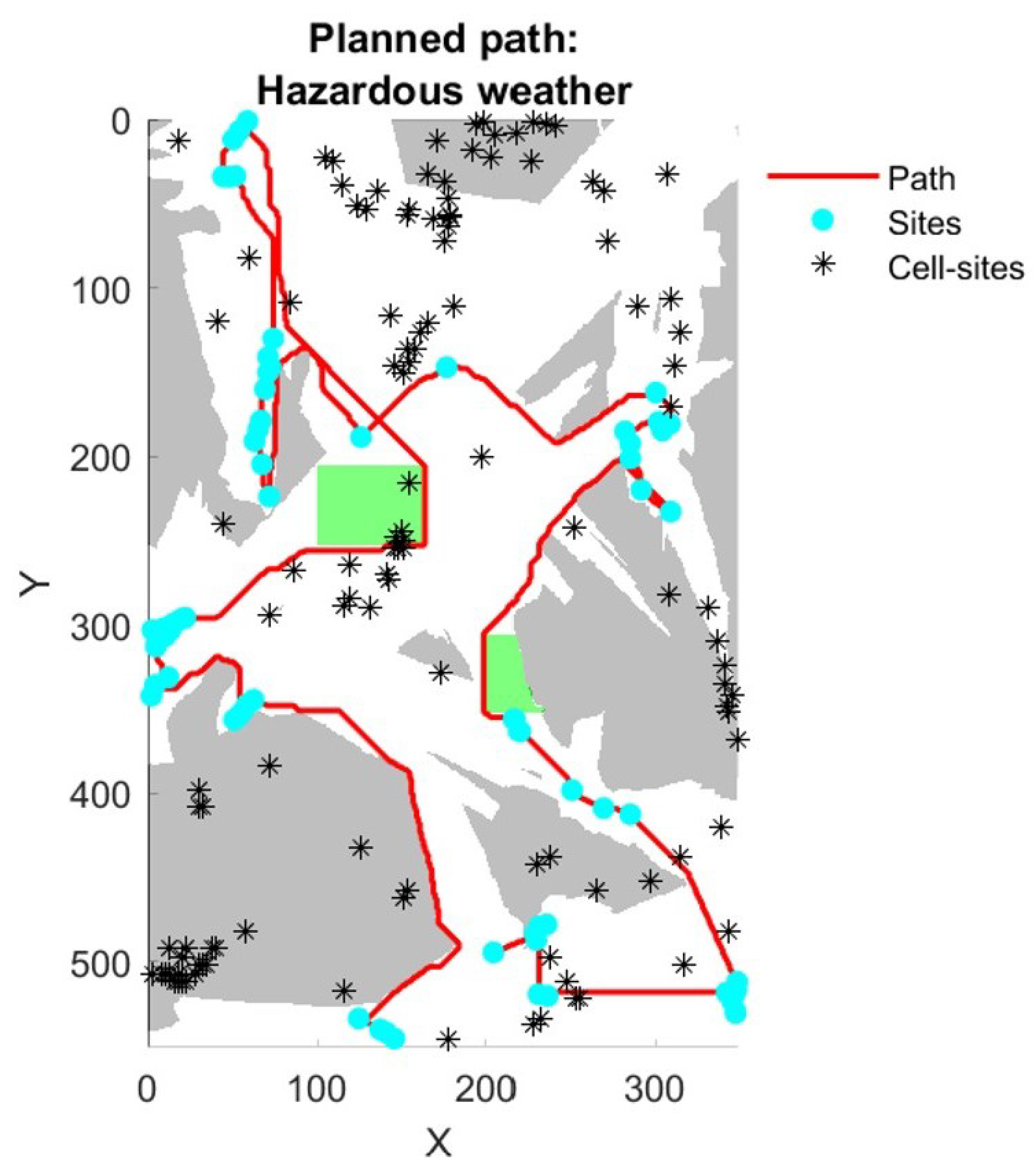
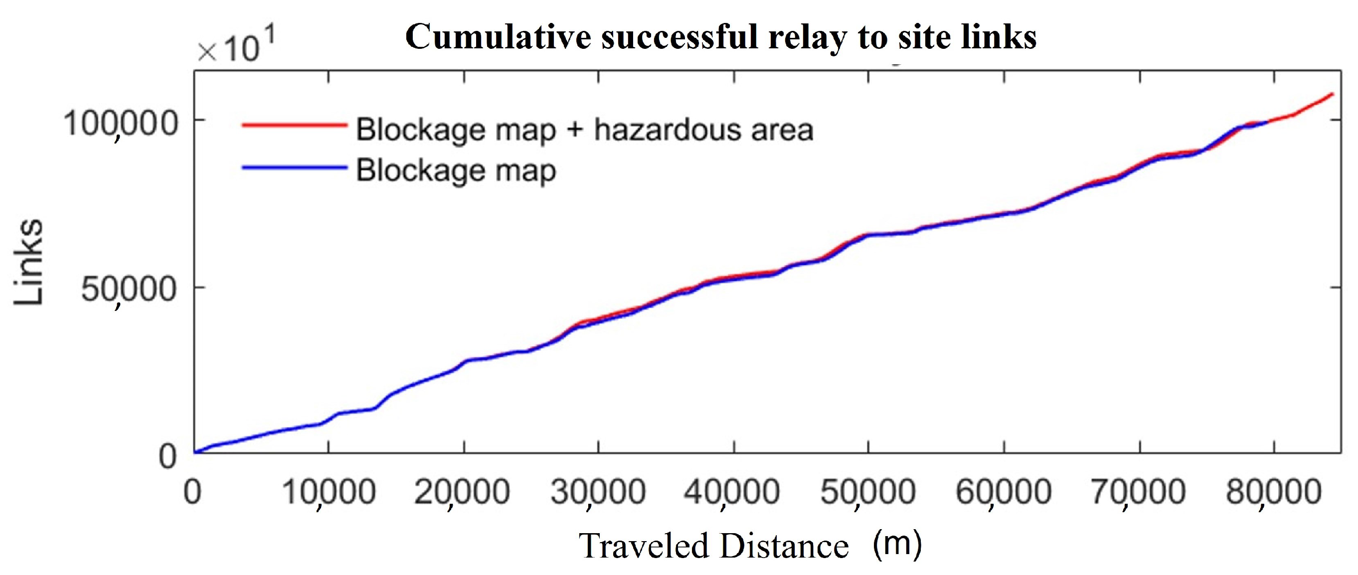
3.2.4. Hazardous Weather

The proposed approach was further extended to consider scenarios where the weather affects the followed path. The hazardous weather conditions considered in this research are heavy rain and strong wind gusts. These scenarios were embedded in the  A  algorithm to force the UAV to take a detour.
Figure 12 shows the obtained results and Table 3 summarizes the average number of successful links under hazardous weather. The results show that by incorporating these scenarios into the  A  algorithm, a slight increase of 6.1% was obtained in path length, and a proportional increase of 6.9% was obtained in successful links. These results were further confirmed by the cumulative link plot shown in Figure 13.

3.3. Energy Awareness and Wind Resilience

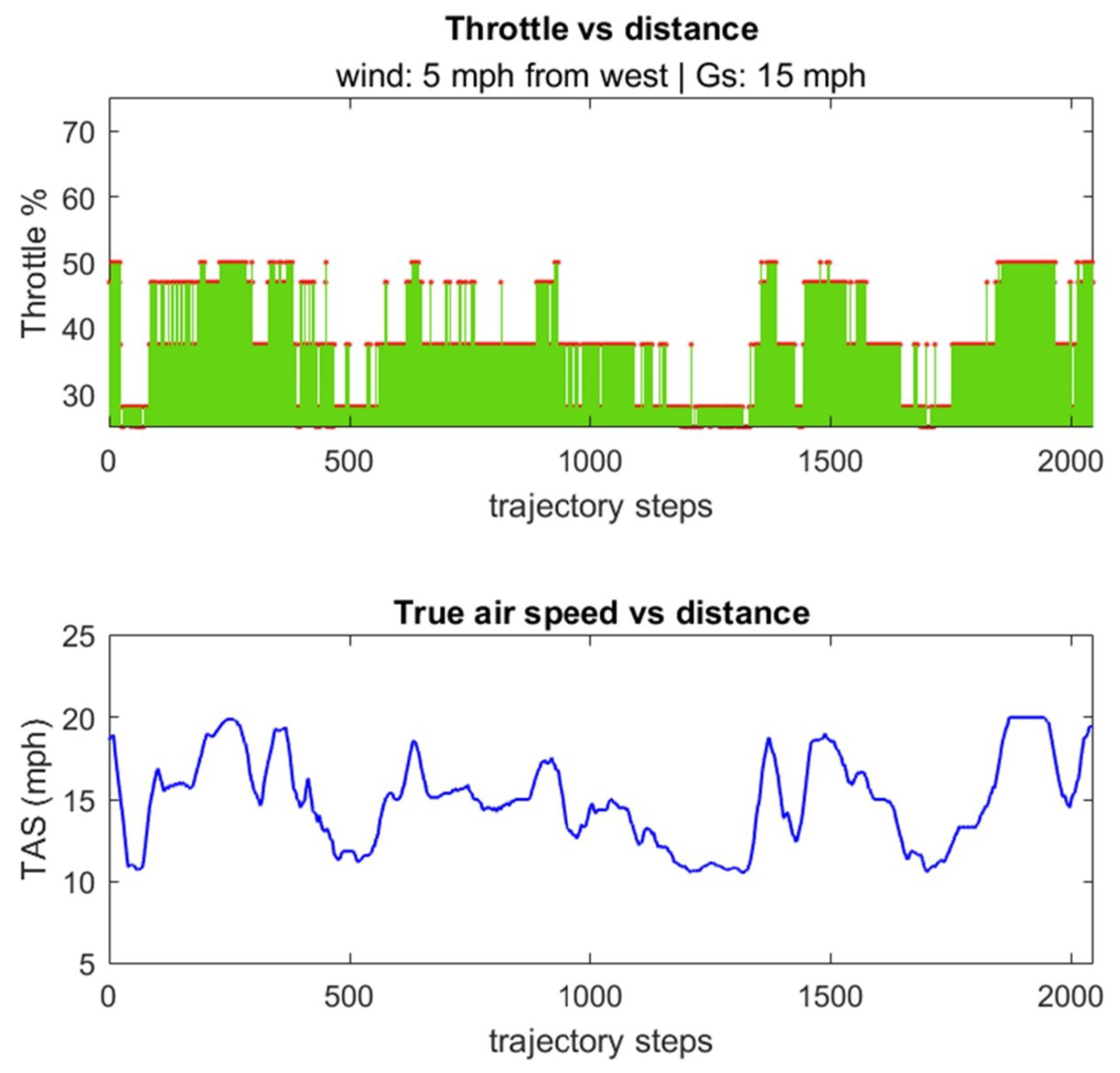
3.3.1. Throttle Modulation Simulation

The effect of wind for throttle modulation was simulated for a fixed ground speed of 15 mph, a wind speed of 5 mph flowing from the west, and a maximum UAV TAS of 40 mph. Specifically, the heading angle was constantly changed throughout the path to model the influence of wind. Figure 14 shows the throttle and true air speed of the UAV to ensure a fixed ground speed. Notably, a required TAS above 15 mph implied that the UAV was flying in the opposite direction to the wind and required an increase in throttle. Conversely, when the TAS was lower than 15 mph, the UAV was flying in the same direction as the wind, such that the throttle could be reduced.

3.3.2. Energy Awareness Simulation

The energy-aware decision-making process for the selection of the first charging visit along the path was assessed under the proposed throttle simulation conditions for an assumed station coordinate of  ( 270 , 140 ) . All three possible conditions discussed in the Section 2 were implemented and are shown in Figure 15.
Figure 16 represents the function  F ( n )  based on the optimization of n, where the points of interest j along the path satisfy
min n = j F ( n ) s . t . F ( n ) > 0 .
The plot shows that the above condition is satisfied in the first 747 steps.

4. Conclusions

This paper presents a path planning approach for resilient communication using UAV relays in MR applications. The key idea of the approach is to provide coverage to areas with poor signal propagation by relaying signals from the available cell-towers. This is performed using a two-stage framework that (a) narrows down the areas of interest that most likely require assistance, and (b) employs an energy-aware and weather-resilient path planning algorithm to relay connection to these areas. The Longley–Rice irregular terrain model was used to compute the pathloss and determine the points of interest. The optimal visiting sequence was then obtained by optimizing a traveling salesman problem, and a viewshed analysis was conducted to determine the mutual visibility region between the points of interest and the cell-towers. This information was used to create a blockage map that feeds an  A  algorithm to prevent the UAV from passing through no coverage areas. The results show that the proposed framework is capable of linking 1.7 more points of interest in comparison with classic methods that do not use the blockage map. The results also confirm that the framework enables the UAV to determine the optimal time to head back towards the charging station using an energy-aware decision-making process based on the throttle level throughout the path.
Future work will consider the use of LIDAR data to provide more realistic and accurate viewshed analysis and path planning algorithms. Additionally, the frequency of transmission will be used to discriminate amongst other towers to improve the reliability of the proposed framework. The algorithm memory consumption will also be addressed in future work to uncover how the implemented algorithm affects the energy of the UAV.

Author Contributions

Conceptualization, M.E.D. and S.A.-R.; methodology, M.E.D. and A.P.; software M.E.D. and C.C.; validation, M.E.D. and J.A.F.-C.; formal analysis, A.P. and C.C.; investigation, M.E.D. and S.A.-R.; data curation, M.E.D. and C.C.; writing—original draft preparation, A.P. and J.A.F.-C.; supervision, S.A.-R. and A.P.; project administration, S.A.-R. and M.E.D. All authors have read and agreed to the published version of the manuscript.

Funding

This research received no external funding.

Data Availability Statement

Publicly available datasets were analyzed in this study. These data can be found here: https://opencellid.org/downloads.php, http://www.gps-routes.co.uk/, http://www.gps-routes.co.uk/routes/home.nsf/national-parks-walks/walking-in-the-lake-district (accessed on 3 March 2024).

Conflicts of Interest

The authors declare no conflicts of interest.

Abbreviations

The following abbreviations are used in this manuscript:
DEM/DTMDigital elevation/terrain model
GPSGlobal positioning system
GSGround speed
LOSLine-of-sight
MRMountain rescue
NLOSNon-line-of-sight
RXReceiver
SRTMShuttle Radar Topography Mission
TASTrue air speed
TSPTraveling salesman problem
TXTransmitter
UAVUnmanned aerial vehicle

References

  1. Conrad, C.; Al-Rubaye, S.; Tsourdos, A. Intelligent Embedded Systems Platform for Vehicular Cyber-Physical Systems. Electronics 2023, 12, 2908. [Google Scholar] [CrossRef]
  2. Guo, W.; Wei, Z.; Gonzalez, O.; Perrusquía, A.; Tsourdos, A. Control Layer Security: A New Security Paradigm for Cooperative Autonomous Systems. In IEEE Vehicular Technology Magazine; IEEE: New York City, NY, USA, 2023. [Google Scholar]
  3. Tazzioli, M. Towards a history of mountain runaways “migrants” and the genealogies of mountain rescue and struggles. J. Alp. Res. 2020. [Google Scholar] [CrossRef]
  4. Fraser, B.; Perrusquía, A.; Panagiotakopoulos, D.; Guo, W. Hybrid deep neural networks for drone high level intent classification using non-cooperative radar data. In Proceedings of the 2023 3rd International Conference on Electrical, Computer, Communications and Mechatronics Engineering (ICECCME), Tenerife, Canary, 19–20 July 2023; IEEE: New York City, NY, USA, 2023; pp. 1–6. [Google Scholar]
  5. San Juan, V.; Santos, M.; Andújar, J.M. Intelligent UAV map generation and discrete path planning for search and rescue operations. Complexity 2018, 2018, 6879419. [Google Scholar] [CrossRef]
  6. Maxama, X.B.; Markus, E.D. A survey on propagation challenges in wireless communication networks over irregular terrains. In Proceedings of the 2018 Open Innovations Conference (OI), Thohoyandou, South Africa, 3–5 October 2018; IEEE: New York City, NY, USA, 2018; pp. 79–86. [Google Scholar]
  7. Li, H.; He, X.; He, W. Review of wireless personal communications radio propagation models in high altitude mountainous areas at 2.6 GHz. Wirel. Pers. Commun. 2018, 101, 735–753. [Google Scholar] [CrossRef]
  8. Harayama, M.; Nishioka, M.; Hayashi, T. 3-D Simulation of MANET with UAV in Mountainous Areas. In Proceedings of the 2020 35th International Technical Conference on Circuits/Systems, Computers and Communications (ITC-CSCC), Nagoya, Japan, 25–28 June 2023; IEEE: New York City, NY, USA, 2020; pp. 166–171. [Google Scholar]
  9. Al-Shehri, S.M.; Loskot, P.; Hirsch, M.J. Enabling connectivity for tactical networks in mountainous areas by aerial relays. Telecommun. Syst. 2019, 71, 561–575. [Google Scholar] [CrossRef]
  10. Zhang, Y.; Arakawa, T.; Krogmeier, J.V.; Anderson, C.R.; Love, D.J.; Buckmaster, D.R. Large-scale cellular coverage analyses for UAV data relay via channel modeling. In Proceedings of the ICC 2020–2020 IEEE International Conference on Communications (ICC), Dublin, Ireland, 7–11 June 2020; IEEE: New York City, NY, USA, 2020; pp. 1–6. [Google Scholar]
  11. Yang, L.; Qi, J.; Xiao, J.; Yong, X. A literature review of UAV 3D path planning. In Proceedings of the 11th World Congress on Intelligent Control and Automation, Shenyang, China, 29 June–4 July 2014; IEEE: New York City, NY, USA, 2014; pp. 2376–2381. [Google Scholar]
  12. Karur, K.; Sharma, N.; Dharmatti, C.; Siegel, J.E. A survey of path planning algorithms for mobile robots. Vehicles 2021, 3, 448–468. [Google Scholar] [CrossRef]
  13. Ermağan, U.; Yıldız, B.; Salman, F.S. A learning based algorithm for drone routing. Comput. Oper. Res. 2022, 137, 105524. [Google Scholar] [CrossRef]
  14. Jensen-Nau, K.R.; Hermans, T.; Leang, K.K. Near-optimal area-coverage path planning of energy-constrained aerial robots with application in autonomous environmental monitoring. IEEE Trans. Autom. Sci. Eng. 2020, 18, 1453–1468. [Google Scholar] [CrossRef]
  15. Chen, W.; Zhao, S.; Shi, Q. Improve stability in UAV relay networks by jointly optimizing communication, trajectory and power. In Proceedings of the 2018 IEEE International Conference on Communication Systems (ICCS), Chengdu, China, 19–21 December 2018; IEEE: New York City, NY, USA, 2018; pp. 180–185. [Google Scholar]
  16. Jiang, X.; Wu, Z.; Yin, Z.; Yang, Z. Power and trajectory optimization for UAV-enabled amplify-and-forward relay networks. IEEE Access 2018, 6, 48688–48696. [Google Scholar] [CrossRef]
  17. Nasrollahi, S.; Mirrezaei, S.M. Towards Communication UAV-Based: Improving Throughput By Optimum Trajectory and Power Allocation; Springer: Berlin/Heidelberg, Germany, 2021. [Google Scholar]
  18. Jiangchun, G.; Guoru, D.; Yitao, X.; Haichao, W.; Qihui, W. Proactive optimization of transmission power and 3D trajectory in UAV-assisted relay systems with mobile ground users. Chin. J. Aeronaut. 2021, 34, 129–144. [Google Scholar]
  19. Padilla, G.E.G.; Kim, K.J.; Park, S.H.; Yu, K.H. Flight path planning of solar-powered UAV for sustainable communication relay. IEEE Robot. Autom. Lett. 2020, 5, 6772–6779. [Google Scholar] [CrossRef]
  20. Yi, P.; Zhu, L.; Zhu, L.; Xiao, Z.; Han, Z.; Xia, X.G. Joint 3-D positioning and power allocation for UAV relay aided by geographic information. IEEE Trans. Wirel. Commun. 2022, 21, 8148–8162. [Google Scholar] [CrossRef]
  21. Chen, J.; Mitra, U.; Gesbert, D. 3D urban UAV relay placement: Linear complexity algorithm and analysis. IEEE Trans. Wirel. Commun. 2021, 20, 5243–5257. [Google Scholar] [CrossRef]
  22. Zhong, X.; Guo, Y.; Li, N.; Chen, Y.; Li, S. Deployment optimization of UAV relay for malfunctioning base station: Model-free approaches. IEEE Trans. Veh. Technol. 2019, 68, 11971–11984. [Google Scholar] [CrossRef]
  23. Xie, H.; Yang, D.; Xiao, L.; Lyu, J. Connectivity-aware 3D UAV path design with deep reinforcement learning. IEEE Trans. Veh. Technol. 2021, 70, 13022–13034. [Google Scholar] [CrossRef]
  24. Yang, S.; Shi, D.; Peng, Y.; Qin, W.; Zhang, Y. Joint Communication-Motion Planning for UAV Relaying in Urban Areas. In Proceedings of the 2021 18th Annual IEEE International Conference on Sensing, Communication, and Networking (SECON), Rome, Italy, 6–9 July 2021; IEEE: New York City, NY, USA, 2021; pp. 1–9. [Google Scholar]
  25. Mardani, A.; Chiaberge, M.; Giaccone, P. Communication-aware UAV path planning. IEEE Access 2019, 7, 52609–52621. [Google Scholar] [CrossRef]
  26. Tseng, F.H.; Liang, T.T.; Lee, C.H.; Der Chou, L.; Chao, H.C. A star search algorithm for civil UAV path planning with 3G communication. In Proceedings of the 2014 Tenth International Conference on Intelligent Information Hiding and Multimedia Signal Processing, Kitakyushu, Japan, 27–29 August 2014; IEEE: New York City, NY, USA, 2014; pp. 942–945. [Google Scholar]
  27. Mozaffari, M.; Saad, W.; Bennis, M.; Nam, Y.H.; Debbah, M. A tutorial on UAVs for wireless networks: Applications, challenges, and open problems. IEEE Commun. Surv. Tutor. 2019, 21, 2334–2360. [Google Scholar] [CrossRef]
  28. Zeng, Y.; Zhang, R.; Lim, T.J. Wireless communications with unmanned aerial vehicles: Opportunities and challenges. IEEE Commun. Mag. 2016, 54, 36–42. [Google Scholar] [CrossRef]
  29. Khawaja, W.; Guvenc, I.; Matolak, D.W.; Fiebig, U.C.; Schneckenburger, N. A survey of air-to-ground propagation channel modeling for unmanned aerial vehicles. IEEE Commun. Surv. Tutor. 2019, 21, 2361–2391. [Google Scholar] [CrossRef]
  30. Mazaherifar, A.; Mostafavi, S. UAV placement and trajectory design optimization: A survey. Wirel. Pers. Commun. 2022, 124, 2191–2210. [Google Scholar] [CrossRef]
  31. Ma, Z.; Gong, H.; Wang, X. An UAV path planning method in complex mountainous area based on a new improved ant colony algorithm. In Proceedings of the 2019 International Conference on Artificial Intelligence and Advanced Manufacturing (AIAM), Dublin, Ireland, 17–19 October 2019; IEEE: New York City, NY, USA, 2019; pp. 125–129. [Google Scholar]
  32. Wang, S.; Zhang, L.; Luo, L.; Zeng, Y. A path planning method of UAV in mountainous environment. In Proceedings of the 2021 IEEE 5th Information Technology, Networking, Electronic and Automation Control Conference (ITNEC), Xi’an, China, 15–17 October 2021; IEEE: New York City, NY, USA, 2021; Volume 5, pp. 1399–1404. [Google Scholar]
  33. Sanchez-Fernandez, A.J.; Romero, L.F.; Bandera, G.; Tabik, S. VPP: Visibility-based path planning heuristic for monitoring large regions of complex terrain using a UAV onboard camera. IEEE J. Sel. Top. Appl. Earth Obs. Remote. Sens. 2021, 15, 944–955. [Google Scholar] [CrossRef]
  34. United States Geological Survey. USGS EROS Archive-Digital Elevation-Shuttle Radar Topography Mission (SRTM) 1 Arc-Second Global. Available online: https://www.usgs.gov/centers/eros/science/usgs-eros-archive-digital-elevation-shuttle-radar-topography-mission-srtm-1#overview (accessed on 5 August 2023).
  35. OpenCellID. Available online: http://opencellid.org (accessed on 10 August 2023).
Figure 1. Two-stage conceptual framework to address path planning optimization for a UAV relay.
Futureinternet 16 00089 g001
Figure 2. Digital elevation model of Keswick.
Futureinternet 16 00089 g002
Figure 3. Mutual viewshed space for successful relaying.
Futureinternet 16 00089 g003
Figure 4. Successful and unsuccessful relay links.
Futureinternet 16 00089 g004
Figure 5. Representation of wind velocity vector and UAV true air speed.
Futureinternet 16 00089 g005
Figure 6. Points of interest reconnaissance across track waypoints.
Futureinternet 16 00089 g006
Figure 7. Elevation contour map.
Futureinternet 16 00089 g007
Figure 8. Boundary region for mutual visibility.
Futureinternet 16 00089 g008
Figure 9. Before and after solving the traveling salesman problem.
Futureinternet 16 00089 g009
Figure 10. A  algorithm planned paths. The yellow area denotes the zones within the visibility region, whilst the purple one denotes the blockage regions.
Futureinternet 16 00089 g010
Figure 11. Cumulative links between the UAV and points of interest throughout the paths.
Futureinternet 16 00089 g011
Figure 12. Blockage map path in the presence of hazardous areas shown in green. The white area denotes the zones within the visibility region, whilst the grey one denotes the blockage regions.
Futureinternet 16 00089 g012
Figure 13. Cumulative links between UAV and points of interest through the paths under hazardous weather.
Futureinternet 16 00089 g013
Figure 14. Throttle and true air speed along path at a ground speed of 15 mph.
Futureinternet 16 00089 g014
Figure 15. Distance to charging station, estimated range and points of interest along the trajectory.
Futureinternet 16 00089 g015
Figure 16. Function  F ( n )  representing the difference between the estimated range and distance to the charging station.
Futureinternet 16 00089 g016
Table 1. Distance between pair of nodes of the TSP solution.
Node ANode BDistance (m)Node ANode BDistance (m)Node ANode BDistance (m)
1420921222154748149
1342645213015247713828
235172233284849126
2415223241224953274
3276273236418245051189
562532425151505211
511628925261335254239
672092627157535441
787182829885556744
89117286663055675061
91015129332425657622
1046309630311655758277
117222403132675859248
121535935362095961739
12351010365138256063650
1314164373862860724468
133493438394556162177
141516439402366263205
161710840411676465219
1637285941425836566321
171816642433186768255
181987434410668691545
19203944451976970756
20323945463547071587
Table 2. Average number of successful links per meter of flight.
Path TypeDistance (m)UAV ElevationNo. of LinksLinks/Distance
Classic62,539100721,93611.543773
Blockage map76,5811001,011,60713.20963
Table 3. Average number of successful links per meter of flight under hazardous weather.
Path TypeDistance (m)UAV ElevationNo. of LinksLinks/Distance
Blockage map76,5811001,011,60713.20963
Blockage map + hazards81,2411001,081,35413.31045
Disclaimer/Publisher’s Note: The statements, opinions and data contained in all publications are solely those of the individual author(s) and contributor(s) and not of MDPI and/or the editor(s). MDPI and/or the editor(s) disclaim responsibility for any injury to people or property resulting from any ideas, methods, instructions or products referred to in the content.

