Abstract
The Internet of Things (IoT) enables a variety of smart applications, including smart home, smart manufacturing, and smart city. By enhancing Business Process Management Systems with IoT capabilities, the execution and monitoring of business processes can be significantly improved. Providing a holistic support for modeling, executing and monitoring IoT-driven processes, however, constitutes a challenge. Existing process modeling and process execution languages, such as BPMN 2.0, are unable to fully meet the IoT characteristics (e.g., asynchronicity and parallelism) of IoT-driven processes. In this article, we present BPMNE4IoT—A holistic framework for modeling, executing and monitoring IoT-driven processes. We introduce various artifacts and events based on the BPMN 2.0 metamodel that allow realizing the desired IoT awareness of business processes. The framework is evaluated along two real-world scenarios from two different domains. Moreover, we present a user study for comparing BPMNE4IoT and BPMN 2.0. In particular, this study has confirmed that the BPMNE4IoT framework facilitates the support of IoT-driven processes.
1. Introduction
The Internet of Things (IoT) has attracted a lot of attention in recent years, making it one of the core technologies for realizing digital twins [1,2]. This trend is fueled by the fact that the electronic components of IoT devices have become cheaper, smaller and more powerful [3]. IoT devices can be found in smart cities, cyber-physical systems, and many other smart applications. As IoT devices are equipped with sensors, actuators, software, protocols, and network interfaces, data can be captured from the physical environment and be exchanged over the IoT network [4]. In this context, sensors are used to capture data from the physical world (e.g., brightness, air quality, temperature or humidity), whereas actuators transform electrical signals into mechanical motion (e.g., translate or rotate) or change physical quantities such as light or pressure [5,6].
Business Process Management (BPM), in turn, deals with the modeling, implementation, execution, monitoring, and analysis of business processes [4,7]. Incorporating IoT capabilities into BPM systems, therefore, offers promising perspectives for bridging the gap between the digital and the physical world, for automating processes and decision making, and for optimizing business processes based on IoT data. By integrating business process with the Internet of Things, it further becomes possible to automate various types of physical tasks, e.g., to start an air conditioner, to turn on/off the light, or to open/close the window [7].
To enable a holistic support for IoT-driven processes, IoT-specific elements are needed that allow modeling, executing and monitoring the IoT-specific aspects of business processes. Modeling IoT-enabled processes shall foster the understanding of how these processes operate. During process enactment, it should be also possible to detect and handle IoT device errors such using faulty sensors or the non-reachability of IoT devices. Though there exist many process modeling languages such as Event Process Chains (EPCs), Petri Nets, Business Process Modeling and Notation (BPMN) 2.0, Flowcharts, and Role Activity Diagrams, these languages are not sufficiently expressive to model IoT-driven BPs [4].
1.1. Problem Identification and Motivation
We illustrate an IoT-driven business process (BP) along an example from smart manufacturing. More precisely, we consider the processing of perishable products (e.g., food, vaccine and chemicals) whose safety and quality control depend on temperature and humidity. We refer to BPs as IoT-driven if they utilize IoT devices and map IoT behavior to process activities and events, respectively.
Imagine a smart factory that receives perishable and/or highly sensitive products, which are then processed and stored. According to [8], such products should be checked (weight, size, temperature, and damage) immediately after receipt. Figure 1 presents the flow of a corresponding BP modeled in terms of BPMN 2.0.
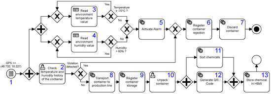
Figure 1.
IoT-driven business process modeled in terms of BPMN 2.0.
The process starts upon the arrival of a container at the receiving department. This can be detected with the help of different sensors, e.g., GPS transmitters, cameras in the goods receiving area or a light barrier at the loading ramp. After the arrival of the container, the monitoring of the environment starts. The warehouse temperature must not be lower than 70 °C and the humidity must be less than or equal 60%. If the measured temperature and humidity are not in the predefined range, an alarm is triggered. Subsequently, the container is rejected and discarded.
In addition to the monitoring of the physical environment, a worker may inspect the history (e.g., NFC code) of the container, e.g., to check whether or not the cooling and humidity chain was interrupted during the transport. Based on this, a decision is made on whether the products meet the specified quality criteria or a violation has occurred. In the latter case, the container is rejected and discarded. Otherwise, it is transported to the production line. Subsequently, the container is registered and unpacked by a worker, the perishable products are sorted, and a QR code is generated in parallel. Finally, the perishable products are stored in the high-bay warehouse. Note that the BP from Figure 1 involves different types of tasks, including manual tasks to be accomplished by humans (cf. Tasks 2 and 10), automated tasks invoking an external service (cf. Tasks 6, 9, and 12) and IoT-driven Tasks (cf. Tasks 3, 4, 5, 7, 8, 11 and 13).
As shown in Figure 1, IoT devices and physical context play a crucial role when executing and monitoring IoT-driven BPs. However, when modeling the latter with BPMN 2.0, it does not become clear which tasks are IoT-related and which are not [9]. Instead, the process model viewer needs to interpret the task label to assess this. Furthermore, no visual distinction can be made between IoT-related service tasks (cf. Tasks 3,4 5, 7, 8, 11 and 13 in Figure 1) and non-IoT-related ones (cf. Tasks 6, 9 and 12 in Figure 1). This aggravates both the readability and comprehensibility of the process model. Note that similar drawbacks hold for events as well. For example, it is not possible to distinguish between an IoT-related conditional event (cf. Event 1) and a Non-IoT-related event. Further note that similar concerns hold when using modeling languages such as Petri Nets, Event-driven Process Chains, and WS-BPEL (Business Process Execution Language). Generally, it is unclear how to model IoT aspects, as the semantics provided by contemporary language constructs has not been conceived to address the specific needs of the IoT domain [6].
To execute IoT-driven BPs, the executable process models need to be deployed on an execution engine. Additionally, the IoT devices need to be set up and configured. However, process engineers are familiar with modeling BPs, but usually do not have the knowledge to manage the interactions between BPs and IoT devices. Note that IoT devices may rely on different technologies (e.g., MQTT, CoAP, Zigbee, LoRa, and LoRaWAN) [10]. Moreover, the response messages returned by IoT sensors may differ. While certain IoT devices return raw sensor data, others deliver JSON-formatted results. Consequently, a process engine must be able to cope with IoT device characteristics [9]. On one hand, tools are needed to control and monitor the process, on the other, mechanisms are required to execute the IoT actions (i.e., sensing and actuating).
There are many efforts to extend BP modeling languages with IoT specific aspects; most existing approaches, however, suffer from four drawbacks:
- IoT-specific extensions do not cover all IoT characteristics, but only support common behaviors (i.e., sensing and/or actuating).
- IoT-specific extensions increase the complexity of the modeling language.
- The proposed solutions focus on the modeling phase, but either neglect execution or depend on specific IoT technologies or application domains.
- Existing approaches either do not support the (real-time) monitoring of IoT-driven BPs or the monitoring approach depends on specific IoT technologies.
Overall, the management of IoT-driven BPs is challenging due to a high complexity and heterogeneity. To remedy the above drawbacks, we consider the following research questions:
- RQ1
- In what way should BPMN be extended to enable the modeling of IoT-driven BPs in a user-friendly way?
- RQ2
- How to design an IoT-driven BPMS that covers the modeling, execution and monitoring of IoT-driven BPs?
- RQ3
- How to support process engineers in modeling, executing and monitoring IoT-driven BPs?
1.2. Contributions
This work proposes a sophisticated framework for the modeling, execution and monitoring of IoT-driven BPs that address problems discussed in Section 1.1. Starting with these problems, we have derived research questions RQ1–RQ3 and then refined them by defining research objectives O1–O8. To model IoT-driven BPs, we propose the use of the defacto standard modeling language BPMN 2.0, as many of its modeling elements can be found in the context of IoT-driven BPs as well (cf. Section 2). To make the involvement of IoT devices in BPs explicit, we extend the BPMN 2.0 metamodel. Our main goal is to provide an intuitive and user-friendly modeling notation for IoT-driven BPs, based on which IoT-driven BPs can be executed, monitored and recorded. Moreover, we propose an appropriate software architecture that enables the integration of IoT devices as well as the flexibility to evolve and maintain the IoT-enhanced BPMS.
This article extend the work we published in [11], as follows:
- We add a backgrounds section that summarizes basic concepts necessary for the understanding of this article.
- We systematically compare the framework with recent works.
- We present more detailed insights into the implementation of the framework.
- We extend the evaluation section by adding a second case study from the smart home domain.
- We present the results of a comprehensive user study.
- We carefully revise the architecture (middleware, IoT services and recording component) according to the feedback obtained from experts.
1.3. Paper Structure
The remainder of this paper is structured as follows. Section 2 presents backgrounds needed to understand the proposed framework, whereas Section 3 outlines the research method and objectives. Section 4 discusses related work with the goal to identify current research gaps. Section 5 introduces the BPMNE4IoT framework for modeling, executing and monitoring IoT-driven BPs, which is then applied in two real-world case studies presented in Section 6. Section 7 describes the user study. Finally, Section 8 discusses our results and Section 9 concludes the article.
2. Background
This section provides basics on the Internet of Things (IoT), business process modeling and BPM system (BPMS).
2.1. Internet of Things
The Internet of Things provides a network of interconnected physical objects (things) equipped with hardware, software, sensors, actuators and network connections that are uniquely addressable based on standard communication protocols [7,12,13]. These interconnected devices allow for gathering data from the physical world, processing these data, acting on the physical world and communicating with other smart things. In this article, we follow the suggestions of the IoT Reference Model [5] and view Sensors and Actuators as key components of IoT devices and environments. An IoT device may consist of multiple sensors and actuators of varying complexity. From the IoT perspective, the following basic types of devices are of interest:
- Sensors enable the detection and measurement of physical and chemical properties such as temperature, brightness, humidity, and pressure. Thereby, a sensor detects the physical quantity and transforms it with appropriate transducers (e.g., inductive, capacitive, magnetic, or piezoelectric) into an electrical output signal [14]. Sensors may be attached to physical objects, placed in the environment, or embedded in physical objects [5]. Usually, the generated sensor data is retrieved by clients on a publish/subscribe basis using web-based protocols (e.g., MQTT, RESTful API) [5,12].
- Actuators are driving elements that transform electrical signals into mechanical motion (e.g., translate, rotate and switch on/off) or changes of physical quantities such as light, pressure or temperature. In general, actuators are able to change the state of a physical entity [5]. They are often controlled and accessed by web services based on the REST paradigm and HTTP [12,15].
Another fundamental aspect of interconnected physical objects in the IoT is the exchange of information between these objects and with external systems. Therefore, the way data and information are structured and exchanged is crucial. In the IoT Reference Model [5], these aspects are defined in the information view layer. This layer allows for an overview of the process information flow [5]. The following message exchanges patterns existing for IoT devices:
- Push pattern: The push pattern is a one-way communication between two parties. Interested parties receive the information they have subscribed to. This pattern can be considered as an event-driven data communication [6]. The data consumer is interested in the events that take place in the physical world and waits for them to occur. The physical world is the element triggering events and informing the data consumer of their occurrence [6].
- Pull pattern: The data consumer fetches the necessary data object when needed or the next data can be processed [16,17]. The data provider notifies the data receiver as soon as new values are available.
2.2. Business Process Modeling
There are several languages that can be used to model business processes, including Event Process Chains (EPC), Petri Nets, and Business Process Modeling and Notation (BPMN) 2.0. A business process is described by Weske [18] as “a set of activities performed in coordination in an organizational and technical environment”. More precisely, a business process specifies the sequence of activities, the constrains for their execution, and the actors to be involved [6,18,19]. BP modeling is crucial to better understand the BP and to identify any problems. Modeled BPs can be analyzed, improved, automated, and optimized [4,19].
In this work, we focus on BPMN 2.0 [20], whose key modeling elements include (1) different activity types (e.g., service, script, message and user tasks) to specify the active parts of a BP, (2) pools and lanes to specify process participants, (3) various types of catching and throwing events (e.g., message, conditional, timer and signal events) to represent elements reacting to other activities, events and messages, (4) different types of gateways (e.g., exclusive, inclusive, parallel and event-based) to split and merge the sequence flow based on conditions, and (5) message flows to describe the interactions between participants. As these modeling elements are also relevant in the context of IoT-driven BPs, many researchers (cf. Section 4) consider BPMN as a suitable basis for modeling IoT-driven BPs.
2.3. Business Process Management Systems (BPMS)
To automate a BP, a BPMS can be used. A BPMS relies on an explicit description of a business process in the form of a process model to coordinate and automate the BP in such a way that all work is conducted at the right time and by the right resource. A BPMS typically provides services for process modeling, process execution, process monitoring and user interaction. Furthermore, the BPMS is responsible for creating and managing process instances. The progress of a process instance is reflected by its trace, which is stored in an event log [7]. Finally, any BPMS architecture needs to be designed in a way that allows for the flexible modeling and execution of BPs [19,21,22].
3. Research Methodology and Objectives
Using the Design Science Research Methodology (DSRM) [23], we follow six iterative steps (cf. Figure 2): (1) problem identification and motivation, (2) definition of solution objectives, (3) design and development, (4) demonstration, (5) evaluation and (6) communication.
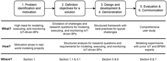
Figure 2.
Design Science Research Methodology applied in this work.
In Step (1), we identified the research problem and motivated it (cf. Section 1.1). Then, we derived the research questions (cf. Section 1.1) and objectives (cf. Section 3) of the framework. In Step (3), we designed and developed the framework required to support the proposed research questions and main contributions. For this purpose, we developed a holistic framework for modeling, executing and monitoring IoT-driven BPs (cf. Section 5). In Step (4), we demonstrated the applicability of the framework in two real-world scenarios from two different domains (cf. Section 6. In Step (5), we present a comprehensive user study as the evaluation of our BPMN extension (cf. Section 7). In Step (6), we discuss our findings, research questions and objectives. Figure 2 summarizes the DSRM steps.
Objectives
The main goal of this work is to address research questions RQ1–RQ3 by developing a BPMS for modeling, executing and monitoring IoT-driven BPs. Due to the high complexity, ambiguity of modeling elements (cf. Figure 1), insufficient support for IoT integration and blurred boundaries between the physical and virtual world, it is challenging to provide a holistic framework (cf. Section 1.1). Based on the problem statement (cf. Section 1.1), the hands-on experiences we have had with implementing IoT-driven BPs [4,9,11,24,25], and a literature study (cf. Section 4), we refine the research questions RQ1–RQ3 and derive the following objectives (O) from them:
- O1
- Visualize IoT involvement in BPs (RQ1): When modeling IoT-driven BPs, IoT involvement should be made transparent and visualized to avoid ambiguity (e.g., to distinguish IoT-related task vs. non IoT-related task), to enable better readability and understandability of the BP (cf. Figure 1), and to represent IoT-specific aspects (e.g., IoT-driven conditions at XOR splits) [4,6,12,24,26].
- O2
- Specify intrinsic IoT characteristics at the process modeling level (RQ1): In an IoT-driven BP, the IoT-intrinsic characteristics such as (1) push and pull interactions, (2) asynchronicity, (3) parallelism, (4) IoT context data (e.g., sensor data), and (5) support for event-based communication need to be specified at a modeling level [6,9,22,27,28].
- O3
- Design IoT extensions for BPMN in a user-friendly manner (RQ1): End-user acceptance as well as the learning of new language concepts are increased by adhering to BPMN 2.0 basic principles. This ensures that the standard elements remain intact and are understandable to users [20]. Therefore, any extension for IoT-driven BPs should stick to BPMN 2.0 and be designed in an intuitive and easy-to-use way [6,12,20,26,29].
- O4
- Execute IoT-driven BPs (RQ2): An IoT-driven engine is needed to enable the IoT-enhanced process execution. This engine should be able to interpret a process model with its IoT-specific extensions and characteristics [6,9,21,24,25,28,30].
- O5
- Provide an IoT-aware process monitoring system (RQ2): In order to monitor IoT-specific process parameters during the execution of IoT-driven BPs (e.g., measured metrics, IoT-device type, device location, and device status), an IoT-aware monitoring system is needed that communicates with the IoT-driven process engine. Moreover, the monitoring of IoT devices shall increase the robustness of the IoT-driven BPs. If a failure occurs (e.g., unreachable IoT device), its source can be detected with the monitoring system and, thus, remedied quicker. Note that monitoring is also critical for ensuring a high quality of task execution [9,25,30,31].
- O6
- Enhance event logs with IoT data (RQ2): In addition to the data generated during process execution, the data captured by IoT devices should be included in the process event logs. Note that the integration of IoT data and process data is accomplished offline in a separate post-processing phase, as IoT data are collected and stored separately from the process data. Thus, an IoT-enhanced event log should be recorded automatically during the execution of IoT-driven BPs [7,9,25,32,33,34].
- O7
- Provide user-friendly interfaces (RQ3): Traditional process modeling tools tend to be overloaded with menus, options, frames, and windows, leading to high cognitive efforts and low acceptance by process modelers, especially non-experts. Consequently, an intuitive user interface should be provided in an environment the modelers of IoT-driven BPs are familiar with [6,12,22].
- O8
- Separation of concerns (RQ3): A difficulty of many IoT-driven BPs is the separation of concerns for BP experts and IoT experts [10]. To foster their collaboration of the two disciplines, a BP expert should be able to model IoT-driven BPs without need to cope with the intrinsic IoT devices and their characteristics. Likewise, the IoT expert should not be tasked with process modeling [10].
4. Related Work
There are many approaches and notations that deal with the modeling, execution, monitoring and recording of IoT-driven BPs. Two options are proposed in this context: (i) extending the BPMN 2.0 metamodel with IoT-specific modeling elements or (ii) relying on the BPMN 2.0 metamodel as-is [6,30,35,36]. Section 4.1 presents approaches that rely on the as-is BPMN 2.0 metamodel, whereas Section 4.2 presents works that extend the BPMN 2.0 metamodel with IoT-specific modeling elements.
4.1. Using BPMN 2.0 Metamodel As-Is
This section discusses works that use the BPMN 2.0 metamodel without extending it. Primarily, BPMN 2.0 is used to create a high-level model that may be enhanced with technical details to become executable by a process engine [6,30].
Ref. [31] presents a BPMN-based approach to manage IoT devices in a Controlled Environment and in Agriculture. To enable interactions with IoT devices (i.e., to enable push and pull interactions) the BPMN script task is used and a sophisticated architecture is proposed. Monitoring IoT-driven BPs based on a web framework developed in Python using the Django framework is proposed.
Refs. [37,38,39] propose the use of the standard BPMN to capture aspects of Wireless Sensor Networks (WSN) applications. Java and C# code is generated and deployed on the Mote Runner WSN platform. The transformation of the BPMN process model into an executable code is performed with patterns.
Ref. [40] proposes modeling business processes with BPMN 2.0 and transforming the resulting process models into artifacts (i.e., Guard-Stage-Milestone (GSM)). The GSM specifications are then deployed and executed on smart objects. For this purpose, a specific infrastructure needs to be set up for each of these objects. [41] suggests using the BPMN resource class to integrate IoT devices as data objects into the model and the BPMN performer class to define the IoT devices involved in the process. To enable their execution, the resulting BPMN 2.0 process models are translated into Callas, an IoT-neutral platform programming code that can be executed by a Callas virtual machine in any IoT device. Ref. [42] focuses on monitoring multi-party IoT-driven BPs. First, the IoT-driven BPs are modeled with standard BPMN 2.0. Then, for each BPMN artifact, an extended GSM (eGSM) model is derived semi-automatically from the process model. Finally, the smart objects are used to transform the BPMN 2.0 artifacts into active entities. An architecture is proposed that enables the monitoring with the above highlighted characteristics. Ref. [43] propose defining IoT-driven BPs in terms of BPMN 2.0 and performing the interaction between IoT devices and BPs based on the Bosch IoT Things Service, thus encapsulating the implementation of the IoT view.
Ref. [44] uses BPMN 2.0 to model IoT-driven BPs. An extended BPMS architecture for the decentralized process execution over mobile nodes is proposed. [6] presents a modeling approach that uses standard BPMN elements. IoT-driven BPs and low-level real-world data are captured in an ontology. To execute the BPMN models, a microservice architecture is proposed. [21] uses BPMN 2.0 service tasks to represent IoT-driven activities, which are then used by the BPMS to invoke the specific web service resources. Additionally, Ref. [21] proposes a layered architecture for executing and monitoring IoT-driven BPs.
All these works argue that BPMN 2.0 itself is capable of modeling IoT-driven BPs without the need to extend the metamodel, as many of the typical BPMN modeling elements (e.g., tasks, events, pools, and lanes) are characteristic for IoT-driven BPs as well [12]. Following such a straightforward approach, however, the involvement of IoT devices is unclear, as BPMN 2.0 does not allow for their explicit representation. Furthermore, the corresponding BP models are difficult to understand due to the ambiguous use of modeling elements (cf. Figure 1). In particular, the resulting IoT-driven BPs lack structure, expressiveness and flexibility. This aggravates both the readability and the comprehensibility of the modeled BP [4,9,24]. Moreover, the complex nesting and ambiguous use of the BPMN modeling elements for IoT devices makes any later extensions or changes difficult.
As the involvement of IoT devices in BPMN 2.0 does not become evident (Objective O1) in most works, BPMN 2.0 is just used as a modeling artifact (cf. Figure 1) that needs to be transformed into an executable language [6]. To support the inherent characteristics of IoT devices (Objective O2), BPMS such as Camunda are not sufficient [4,6,9,24]. Consequently, the IoT-driven BPs modeled with BPMN 2.0 need to be (1) converted to a IoT neutral-platform programming code (e.g., Callas, Java, or C#), (2) an appropriate ontology to extend BPs with context data [6] is required, (3) or a suitable IoT middleware needs to be introduced for the IoT-driven BPs (cf. Objective O4). The latter is particularly challenging, as existing middleware differs in the underlying technologies [45]. For instance, ref. [39] generates Java and C# code for deploying it on the Monte Runner WSN platform; ref. [41] translates the model of an IoT-driven BP into Callas; Valderas et al. [6] suggests combining BPMN with ontologies to execute IoT-driven BPs. Finally, Seiger et al. [21] proposes the use of a layered architecture for executing IoT-driven BPs.
For the monitoring of IoT-driven BPs, specific solutions exist. As standard BPMN elements (e.g., service or script tasks) are used to express the IoT involvement in processes, IoT behavior cannot be explicitly monitored and tracked (e.g., in an event log) (Objectives O5 and O6). For example, it needs to be monitored which IoT devices are currently processing, in what state these devices are (e.g., running, waiting or error), and what outputs are produced by them. Ref. [31] developed a Django web framework to monitor IoT devices as well as the progress of the process state. Ref. [42] uses smart objects, which communicate the state changes of their process or IoT devices to the architecture. In turn, these changes are forwarded to the monitoring system.
4.2. Extending the BPMN 2.0 Metamodel with IoT-Specific Modeling Elements
This section deals with works that extend the BPMN 2.0 metamodel to explicitly capture IoT aspects in BP models. An overview of related approaches extending BPMN with IoT-specific modeling elements is given in Table 1.
uBPMN [26], extends BPMN 2.0 with five task types: (1) sensor tasks to collect physical data, (2) reader tasks to collect data from ubiquitous technology (e.g., RFID, NFC and magnetic stripes), (3) image tasks to collect data from video streams, (4) audio tasks to collect information from an audio stream and (5) collector tasks to collect information except from sensors (e.g., databases, files or proxy entity). For each activity type, there is a start and intermediate event. Moreover, uBPMN extends BPMN with IoT-driven Data and Context Objects. A Data Object is used to represent the data transmitted from the IoT devices. To describe attributes of the physical context (e.g., brightness > 10) the Context Object may be used.
The Stream Processing Unit SPU [46] extends BPMN 2.0 with two tasks for managing data streams in the context of IoT-driven BPs: (1) Event stream specification tasks manage the stream events and their parameters. To stop the data stream, a condition needs to be specified for this task. (2) An Event stream processing task, in turn, manages the stream events and their parameters. To stop the data stream, a condition needs to be specified for this task. Furthermore, the concept of the data stream is introduced to collect input or output data from smart devices. For this purpose, standard BPMN data objects are transformed into an input/output event stream data object.
BPMNE4WSN [47] extends BPMN 2.0 to represent Wireless Sensor Networks (WSNs). For this purpose, a WSN task, a WSN pool, and performance annotations are introduced. The WSN task corresponds to an action performed in a WSN process and includes six attributes: (1) tWSNOperation to bind a WSN operation, (2) actionType to define the operation as sensing (?) or actuation (!), (3) isCommandAction to define a WSN task as a command action, (4) tWSNPerformer to define the resource needed to perform the task, (5) tActionPerformer extending tWSNPerformer to represent the nodes that are supposed to execute the tWSNOperation and (6) isEventDriven to mark a WSN Task as event-driven. Each attribute has its own icon and is displayed accordingly (when enabled) in a WSN Task in the upper left corner.
Refs. [48,49] add three IoT-specific modeling elements to BPMN 2.0 (1) a sensing task for representing pull interactions, (2) an actuation task for representing push interactions and (3) an empty pool for representing physical entities (e.g., chocolate). Within such a pool, an icon may be displayed to represent the special process role. Ref. [50] describes a BPMN metamodel extension for representing physical entities as well as their interaction with smart devices. This metamodel includes the (1) PhysicalObject to model physical entities, (2) SensingTask to enable pull interactions, (3) SensingAssociation to enable a flow of physical information (pull) from a physical entity to a sensor, (4) ActuatingTask for push interactions and Actuating Association to represent actuator commands, which may can be considered as a flow of physical interaction (pull). For the SensingAssociation and ActuatingAssociation, Sperner proposes the reuse of the same stencil as defined for a DataAssociation.
Ref. [51] extends BPMN to enable the management of smart services by sensing data from smart devices with an IoT Sensor Activity. To enable push interactions, an IoT Service Activity is introduced. Ref. [52] provides a BPMN extension that includes (1) a Sensor Device to determine the type of sensor (e.g., temperature sensor, brightness sensor, or pressure sensor), (2) a Sensor Service to define the function of the sensor device (e.g., request sensor data) and (3) a Handler to specify the technology used to communicate with the sensor (e.g., REST-API, MQTT or WiFi).
BPMNE4CPS [53] suggests extending the BPMN 2.0 Service Task in the context of Cyber–Physical Systems (CPS). Besides sensor and actuator tasks, the extension introduces the following additional task types (1) web service tasks for web services (i.e., REST-API requests), (2) embedded service tasks for executing software inside the smart device and (3) cloud service task to trigger operations in the cloud. Furthermore, a pool marked with a world symbol is introduced to represent a physical entity.
Ref. [54] proposes a BPMN extension to represent location-specific, sensitive information based on sensors (e.g., GPS). The following event types are introduced: (1) the position achieved event that occurs when the participant reaches a predefined location, (2) the position update event to notify the BPMS about the position change and (3) the conditional positional event that occurs when a participant reaches a predefined maximum distance of a location.
Ref. [55] extends the BPMN 2.0 pool with a cloud icon labeled as IoT to visually represent the IoT involvement. To represent a human being involved in the IoT pool, additionally, a smiley may attached to the pool. [56] extends the BPMN 2.0 pool, with a cloud as marker to indicate that the pool communicates with a smart scenario (e.g., smart home or smart factory). Note that the marker may contain the label pub for public, priv for private and hybrid for hybrid clouds.
Discussion of Related Work
As a major drawback, all presented approaches do not fully cover IoT-specific characteristics (cf. Objectives O1 and O2), but only support common behaviors (i.e., sensing and/or actuating). For example, none of the extensions consider asynchronous and parallel IoT interactions (push/pull) within a task, though this behavior can be frequently observed when controlling actuators [27]. BPMN extensions such as uBPMN, BPMN4WSN and BPMN4CPS introduce further task types or events in addition to sensor and actuator tasks. However, these additional language elements are by far too specific (e.g., uBPMN-audio, image, and reader tasks and events) or only support a certain IoT domain, e.g., Wireless Sensor Networks or Cyber-Physical Systems (cf. Objective O3). As another drawback, in most cases the extensions are considered solely from a theoretical point of view, but neglect implementation issues [35], i.e., these works describe IoT-specific extensions of the BPMN metamodel, but do not provide an extended BPMN modeler to support process engineers in modeling IoT-driven BPs (cf. Objectives O7 and O8). Moreover, the proposed solutions focus on extending the BPMN from a modeling perspective, but the resulting models are not executable (cf. Objective O4). Nevertheless, extensions exist that provide both a modeler and an engine with the specifics of the extension as well [46,47,51]. As explained, however, these approaches are either too specific, only support a specific domain, or depend on specific IoT technologies, making it difficult to maintain the system. As another drawback none of the extensions introduces a real-time monitoring or a recording approach for IoT-driven BPs in the context of an holistic approach (cf. Objectives O5 and O6).
As opposed to our framework, none of the discussed works provides a holistic framework for modeling, executing, monitoring and recording IoT-driven BPs. The framework proposes a BPMN extension with IoT-specific modeling elements. However, we have extended BPMN with domain-independent modeling elements, i.e., our extension can be used in any domain. Furthermore, we ensure the support of IoT-specific behavior such as asynchronicity, parallelism, and IoT expressions. To support a wide range of IoT technologies, we designed our software architecture that allows adding further IoT communication protocols as well. The main goal of our work is to address these drawbacks of existing approaches and to propose a holistic framework for IoT-driven BPs addressing the Objectives O1–O8.

Table 1.
Overview on related approach extending BPMN 2.0 for IoT-driven BPs.
Table 1.
Overview on related approach extending BPMN 2.0 for IoT-driven BPs.
| Approach | Modeling | Executing | Monitoring | Logging | User Interface | Domain Independent |
|---|---|---|---|---|---|---|
| uBPMN [26] | ✓ | ✗ | ✗ | ✗ | ✗ | ✗ |
| SPU [46] | ✓ | ✓ | ✓ | ✗ | ✗ | ✓ |
| BPMN4WSN [47] | ✓ | ✓ | ✓ | ✗ | ✗ | ✗ |
| Meyer et al. [48,49] | ✓ | ✗ | ✗ | ✗ | ✗ | ✓ |
| Park et al. [51] | ✓ | ✗ | ✗ | ✗ | ✓ | ✓ |
| BPMN4CPS [53] | ✓ | ✓ | ✗ | ✗ | ✓ | ✗ |
| Kozel et al. [54] | ✓ | ✗ | ✗ | ✗ | ✗ | ✓ |
| Petrach et al. [55] | ✓ | ✗ | ✗ | ✗ | ✗ | ✓ |
5. BPMNE4IoT–A Holistic Framework for IoT-Driven BPs
This section presents BPMNE4IoT—a holistic framework for modeling, executing, monitoring and recording IoT-driven BPs based on a BPMN 2.0 extension. In all these BPM lifecycle phases, we provide sophisticated visualizations for the support of various user groups. Our extension provides suitable modeling elements to describe the interactions between processes and IoT devices. This includes the involvement of IoT devices and their behavior. Moreover, BPMNE4IoT enables the real-time monitoring of IoT-driven BPs, visualizing the current state of the involved IoT devices and aligning them along the process flow.
Section 5 is structured as follows: Section 5.1 presents the extended BPMN 2.0 metamodel for modeling, executing, monitoring and recording the IoT-driven BPs. The corresponding notation is presented in Section 5.2 and illustrated in the examples. Section 5.3 presents an advanced architecture for implementing the BPMNE4IoT framework. Finally, Section 5.4 elaborates on the execution of IoT-driven BPs based on BPMNE4IoT.
5.1. Metamodel
To meet Objectives O1, O2, and O3, we decided to use BPMN 2.0 as a basis for modeling IoT-driven BPs. As BPMN 2.0 has shown several drawbacks in this context (cf. Section 1.1), we extend BPMN 2.0 with IoT-specific modeling elements. This extension is based on the procedure described in [57]: First of all, we describe the extension at the metamodel level (also called Abstract Syntax) and then present concrete examples utilizing our extension for the Concrete Syntax. Figure 3 shows the proposed extension of the BPMN 2.0 in UML. Note that the white classes are already part of BPMN 2.0, whereas the red classes reflect the BPMNE4IoT extension. To cover the characteristics of IoT-driven BPs at the modeling level, we extended the BPMN 2.0 classes Activity, Throw Event, and Catch Event [20] with new subclasses (cf. Figure 3). The following is an abstract description of the artifacts and events.
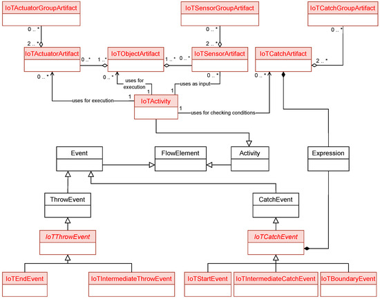
Figure 3.
BPMNE4IoT metamodel.
Artifacts:
- IoTActivity: To an IoTActivity, one or more IoT artifacts are attached.
- IoTActuator(Group)Artifact: The IoTActuatorArtifact represents a physical actuator that contains the information required for the execution of the physical actuator. This artifact is also used for monitoring the state of the physical actuator. To increase its abstraction, an IoTActuatorGroupArtifact may combine multiple IoTActuatorArtifacts.
- IoTSensor(Group)Artifact: The IoTSensorArtifact represents a physical sensor, containing the information required for querying the physical sensor. This artifact is also used for monitoring the state the of the physical sensor. To increase its abstraction, an IoTSensorGroupArtifact may combine multiple IoTSensorArtifacts.
- IoTCatch(Group)Artifact: An IoTCatchArtifact allows for checking a condition based on a sensor value, i.e., it contains the information required for condition checking. An IoTCatchGroupArtifact, in turn, combines multiple IoTCatchArtifacts to increase the abstraction level.
- IoTObjectArtifact: An IoTObjectArtifact represents a physical object (e.g., a robot or a smart machine), which may contain multiple IoTSensorArtifacts and IoTActuatorArtifacts. Furthermore, this artifact is used for monitoring the state of a physical object.
Events:
- IoTStartEvent: An IoTStartEvent refers to a physical sensor and enables the start of an IoT-driven BP.
- IoTEndEvent: An IoTEndEvent represents a physical actuator that triggers the execution of an actuator, terminating the corresponding process instance.
- IoTIntermediateThrowEvent: An IoTIntermediateThrowEvent refers to a physical actuator, enabling the control of an actuator along the sequence flow.
- IoTIntermediateCatchEvent: An IoTIntermediateCatchEvent represents a sensor that enables the process instance to check a condition based on the received sensor data.
- IoTBoundaryEvent: An IoTBoundaryEvent represents a physical sensor being attached to a task. If the defined condition is fulfilled, the sequence flow is redirected.
5.2. BPMNE4IoT Notation
The BPMN 2.0 [20] notation offers various modeling elements (cf. Section 2.2) to shape a business process as well as to define its behavior [18,19,26]. The IoT extension introduced in Section 5 provides suitable modeling concepts for IoT-driven BPs that can be used to incorporate new behavior within business processes (e.g, context awareness, IoT-driven conditions, asynchronicity, and parallelism). As we extend the BPMN 2.0 metamodel (cf. Figure 3) with IoT-specific modeling elements, we need to complement the BPMN 2.0 notation accordingly (cf. Figure 4). In the following, each element of BPMNE4IoT is described. Note that all elements are decorated with a WLAN icon and labeled as IoT. Moreover, the letter in the upper left corner indicates the artifact type (i.e., “A” for actuator and “S” for sensor). All artifacts may only be connected to a task using an association.
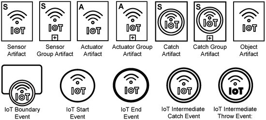
Figure 4.
BPMNE4IoT with the notation of the IoT-specific modeling elements.
5.2.1. Sensor Artifact and Sensor Group Artifact
A sensor artifact can represent various sensors whose measurements become relevant during process execution (e.g., measuring humidity, pressure or brightness). Thus, it enables the collection of data from the physical environment and processes the context, respectively. When connecting a task with a sensor artifact, the corresponding sensor may be queried by the task during its execution. A sensor artifact captures all necessary information about the sensor. The task associated with a sensor artifact may only be successfully completed after having received a positive response from the physical sensor. Note that the representation of sensors as artifacts allows linking any number of sensors to a task. In turn, a sensor artifact may be arbitrarily combined with other artifacts (cf. Figure 5). In such a case, the sensors are simultaneously queried during task execution.
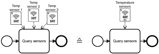
Figure 5.
Usage of Sensor Artifact and Sensor Group Artifact.
Individual sensor artifacts may be aggregated to a sensor group artifact in order to increase the abstraction level. A sensor group artifact shows the same behavior as a sensor artifact. Moreover, it is represented by a collapsed sensor artifact (cf. Figure 4). As soon as a task becomes activated, all physical sensors defined in the sensor group artifact are pulled (push/pull interaction). The returned sensor values are stored and may then be used in the further course of the process execution. Note that the representation of the artifact is generic, allowing for the representation of arbitrary sensor types. Moreover, text annotations may be used, for example, to designate artifacts and events.
5.2.2. Actuator Artifact and Actuator Group Artifact
An actuator artifact (cf. Figure 6) allows modeling actuators (e.g., electric motor, relay and light). This enables the process to react to situations, e.g., by starting the air conditioner as soon as a certain temperature threshold is exceeded. An actuator is controlled by the task associated with the corresponding actuator artifact. All necessary information about the actuator is captured by the actuator artifact. The corresponding task is completed successfully once it has received a positive response from the actuator (e.g., status code 200 OK). Note that the artifact is represented in a generic way, allowing for the representation of arbitrary actuator types.
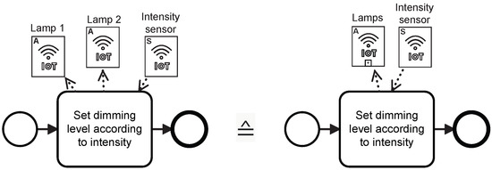
Figure 6.
Usage of Actuator Artifact and Actuator Group Artifact.
Individual actuator artifacts may be combined to an actuator group artifact in order to increase the abstraction level. An actuator group artifact shows the same behavior as an actuator artifact and is represented by a collapsed actuator artifact (cf. Figure 6). As soon as a task becomes activated, all physical actuators defined by the actuator group artifact are controlled (push/pull interaction). The corresponding task is completed successfully once it has received a positive response from all physical actuators. Figure 6 shows an example combining both sensor and actuator artifacts.
5.2.3. Catch Artifact and Catch Group Artifact
A catch artifact (cf. Figure 7) allows for checking a condition during task processing in combination with a boundary timer event. Immediately after starting the task, its condition is continuously checked. All necessary information about the condition is provided by the catch artifact. The task may be completed successfully only when meeting the specified condition. If the condition is not satisfied within the time period specified by the boundary timer event, the sequence flow attached to this event is executed (cf. Figure 7). Note that if other artifacts are attached to the task, their execution and verification run in parallel. Furthermore, the catch artifact may be used in combination with the actuator artifact to support asynchronous actuator calls (cf. Figure 8). As soon as the task becomes activated, the actuator artifact is processed (send command to the physical actuator). While executing the actuation command (e.g., start conveyor belt), the condition defined in the catch artifact is checked in parallel. The conveyor belt is active until the condition set out by the catch artifact becomes fulfilled. If the latter applies, the task is completed successfully.
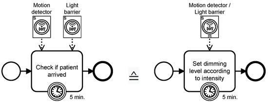
Figure 7.
Usage of Catch Artifact and Catch Group Artifact.
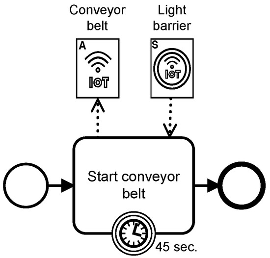
Figure 8.
Usage of Catch Artifact and Actuator Artifact.
Individual catch artifacts may be aggregated to a catch group artifact to increase the abstraction level. A catch group artifact shows the same behavior as a catch artifact and is represented by a collapsed catch artifact (cf. Figure 4). As depicted in Figure 7, the group artifact aggregates multiple catch artifacts to increase the abstraction level. As soon as the task becomes activated, all conditions specified in the catch group artifact are continuously checked in parallel. The task is successfully completed as soon as all conditions defined in the catch group artifact are met. Note that the conditions are logically linked by an AND operator (cf. Figure 7).
5.2.4. Object Artifact
An object artifact (cf. Figure 4) enables the modeling of physical objects (e.g., robot, machine or smart factory). As illustrated in Figure 9, an object artifact may contain both sensors and actuators. On one hand, this allows hiding unnecessary information from domain experts. On the other, the modeling becomes more accurate.
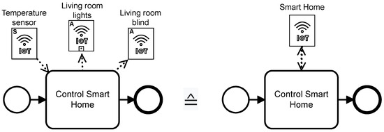
Figure 9.
Usage of Object Artifact.
5.2.5. IoT Boundary Event
An IoT boundary event (cf. Figure 10) is attached to a task. This element may be used to define a condition and to redirect the sequence flow if this condition becomes fulfilled during the task execution. As soon as the task becomes activated, the condition defined in the IoT boundary event is continuously checked. The condition check stops either upon task completion or in case the condition becomes fulfilled before task completition. For example, in Figure 10, a workpiece is weighed. During the execution of this task, the weight is continuously checked using a load cell sensor. If the weight exceeds 1000 kg, an alarm is triggered, as the conveyor belt can only transport a maximum of 1000 kg. Otherwise, the process ends. Note that all events use the sequence flow as a connection type.
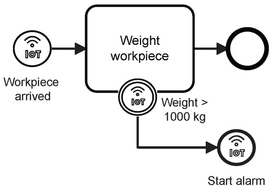
Figure 10.
Usage of IoT Boundary, IoT Start and IoT End event.
5.2.6. IoT Start Event
To enable the start of an IoT-driven process depending on an IoT sensor and a corresponding physical condition (e.g., motion detected, 20 °C, or workpiece arrived), the IoT start event (cf. Figure 10) may be used. When using this element the process instance does not start directly, but only upon fulfillment of the condition. A decision can be made between the at-most-once and at-least-once options. If the at-most-once option is selected, only one instance may be created at runtime when meeting the condition. The at-least-once option allows creating any number of instances upon the fulfillment of the condition (e.g., check every 200 ms if temperature ≥ 20 °C).
5.2.7. IoT End Event
An IoT end event (cf. Figure 10) triggers the execution and/or control of an actuator and terminates the corresponding process instance. In Figure 10, for example, the IoT end event starts an alarm if the weight exceeds 1000 kg. Then, it terminates the process instance. Unlike the IoT start event, the IoT end event has a thicker border.
5.2.8. IoT Intermediate Catch Event
An IoT intermediate catch event (cf. Figure 11) is linked to an IoT sensor. This element enables the process to check a physical condition along the sequence flow (e.g., 60 decibels, motion detected, or location arrived). More precisely, when reaching an IoT intermediate catch event, the sequence flow does not continue until its corresponding condition is met. Note that an artifact (e.g., sensor, actuator, catch or object artifact) must not be linked to an IoT intermediate catch event.
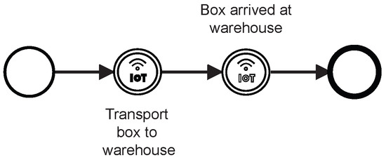
Figure 11.
Usage of IoT intermediate catch and throw event.
5.2.9. IoT Intermediate Throw Event
To control an actuator along a sequence flow, the IoT intermediate throw event (cf. Figure 11) may be used. Semantically, such events correspond to a task with a linked actuator artifact. However, only one actuator may be controlled at the same time in the context of an IoT intermediate throw event. The latter is successfully completed upon receipt of a positive response from the actuator. Only then, the sequence flow continues. Furthermore, the IoT intermediate throw event may affect the physical world through actuators (e.g., open window, start air conditioner and turn on light). Note that an artifact (e.g., sensor, actuator, catch or object artifact) must not be linked to an IoT intermediate throw event.
5.3. Architecture
A holistic IoT-driven BPMS supporting the modeling, execution, monitoring and logging of IoT-driven BPs based on BPMNE4IoT (https://github.com/elmurd0r/bpmne4iot, accessed on 20 January 2023)) (see RQ2) necessitates an advanced architecture (Objectives O4, O5 and O6). In particular, such an architecture shall implement the behavior of the IoT-specific artifacts and events introduced in Section 5.2. Figure 12 depicts a coarse-grained view on the BPMNE4IoT architecture, highlighting our contribution in green. Basically, the architecture consists of three main components, i.e., IoT Devices, IoT Middleware and IoT-driven BPMS.
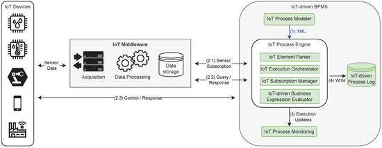
Figure 12.
Abstract view on System architecture and communication between system components.
IoT Devices are used to measure the state of the physical world and to digitize it or to change the state of the physical world (e.g., turn/off the light). IoT devices may include sensors and actuators that, in turn, may be combined into more complex ”things” such as a smart fridge or smart car. The data collected with IoT devices is made available and may be further exploited. In this context, either the IoT devices themselves provide access to the data or a gateway can be used. Note that any connection to the respective IoT devices or gateways is made through standard security mechanisms to ensure data protection. This becomes necessary, as IoT devices generate a large amount of sensitive data, providing a potential attack surface. Particularly, actuators are frequently affected, as they have the ability to influence the state of the physical world.
IoT Middleware is responsible for data acquisition, data processing and data storage. As the data formats and access methods (e.g., push or pull) of the various data sources differ significantly, it becomes necessary to use middleware (e.g., Apache Kafka) that is able to cope with this heterogeneity. Moreover, the middleware processes the obtained sensor data, i.e., it transforms the heterogeneous data into a unified from, validates the data, and cleans it (if required). Subsequently, the IoT data needs to be stored to enable access at any point in time. In this context, IoT devices often run on reduced power and send their data only with a limited frequency to keep power consumption low. Consequently, if the data are not immediately stored (e.g., in a database), no data might be available. Moreover, the middleware handles standard security mechanisms such as the encryption of data traffic and authentication. These mechanisms prevent unauthorized access to the IoT data.
As a core component of the architecture, the IoT-driven BPMS enables the holistic integration of BPM with IoT. In detail, this component comprises the following sub-components.
- The IoT Process Modeler enables the modeling of IoT-driven processes. This sub-component is based on bpmn.io (https://bpmn.io/, accessed on 18 January 2023)) extended with the elements and metamodel described in Section 5. To enable the configuration of the IoT characteristics (cf. Section 2.1), the extended properties panel may be used (Objectives O7 and O8).
- The IoT Process Engine executes IoT-driven BPs that contain IoT-specific information. The process model contains both IoT-specific and Non-IoT-specific information to execute the IoT-driven BP. In our proof-of-concept, the open source Javascript workflow engine (https://github.com/paed01/bpmn-engine, accessed on 19 December 2022)) serves as the basis for executing the IoT-driven BPs. In detail:
- –
- We extend the process engine with an IoT Element Parser, which parses all IoT-specific information (e.g., endpoints; defined condition, i.e., for the IoT start event; and device information) from the exported XML file and processes it for its further use by the engine.
- –
- The IoT Execution Orchestrator receives the IoT-specific information during process execution and orchestrates the execution of the IoT artifacts and events.
- –
- The IoT Subscription Manager allows the process instances to subscribe and unsubscribe to IoT devices as well as to integrate the real-world data provided by the IoT devices and cleansed by the middleware.
- –
- The IoT-driven Business Expression Evaluator accepts IoT data and expressions (e.g., light barrier is interrupted) and evaluates them based on the received sensor data.
- IoT Process Monitoring enables the monitoring of IoT-driven BPs using a similar visualization as the IoT Process Modeler. In particular, IoT Process Monitoring receives execution events and displays them in the process monitoring view.
- IoT-driven Process Log may be any persistent storage (e.g., PostgreSQL) recording the process information and IoT device data during the process execution.
Due to the modular and flexible structure of the architecture, it becomes possible to add components or to alter existing ones. Note that this enables a broad support of different technologies. For example, IoT devices may be integrated regardless of the underlying technologies (e.g., MQTT, CoAP, Zigbee, LoRa and LoRaWAN) on which they rely.
5.4. Executing IoT-Driven Business Processes
When executing IoT-driven BPs, a distinction is made between the deployment and execution phases. To illustrate this, the communication between the components of the architecture is shown in Figure 12 as well. Note that the deployment phase is represented by Step (1) and the execution phase by Steps (2)–(4).
Deployment Phase. The process engineer models an IoT-driven BP and configures its IoT parameters (e.g., endpoint and expressions). The configured BP model then contains both information specific to IoT and not specific to IoT that is required to execute the IoT-driven BP. The BP model is encoded as an XML file, which is deployed to the process engine. Note that this XML file is machine-readable and, thus, is executable (cf. Step (1)).
Execution Phase. When creating a new process instance, the IoT process engine reads the XML file and then starts the execution of this process instance. As soon as the engine encounters an IoT artifact or event during the process execution, the IoT Element Parser parses the IoT-specific information. In turn, the IoT Execution Orchestrator ensures that the required action is taken. If sensor values are required, e.g., to check expressions in the IoT start event, the IoT Subscription Manager enables sensor subscriptions at the IoT Middleware in Step (2.1). The middleware responds regularly with the most recent sensor data as long as the subscription is necessary. These data are then sent to the IoT-driven Business Expression Evaluator, which uses it to evaluate expressions, e.g., for the IoT start event, IoT boundary event, or the IoT catch artifact. Another option to query the data is an active (pull) middleware request to instantly fetch sensor values (see Step (2.2)). Additionally, it is possible to send commands to actuators. The communication between the actuators and the IoT-driven BPMS is depicted in Step (2.3). In Step (3), all progress updates as well as failures during the execution of an IoT-driven process are sent to the IoT Process Monitoring via execution updates. The latter then displays these execution updates.
5.5. IoT-Driven Event Log
As described in Section 5.3, an IoT-driven Event Log is recorded by the IoT-driven BPMS (cf. Step (4)). This log combines the known process event log with the IoT-related data. Figure 13 shows a segment of an IoT-driven process from a smart factory and the resulting excerpt of the generated log. The depicted IoT-driven BP measures the temperature using a sensor artifact. Subsequently, the oven valve is opened using an actuator artifact in combination with a sensor catch artifact. The columns of the event log are as follows:
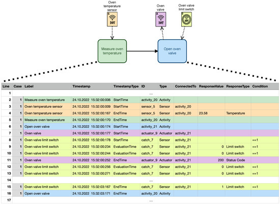
Figure 13.
Excerpt of an output event log showing a segment of an IoT-driven Process in CSV Format.
- Case. Unique identifier of the case to which the event belongs.
- Label. Label of the element (e.g., activity, events, and artifacts) to which the event belongs.
- Timestamp. Time at which the event occurred.
- TimestampType. Indicates the type of the timestamp. This can be either StartTime, EndTime or EvaluationTime.
- ID. Unique identifier of the element to which the event refers.
- Type. Type of the element to which the event refers (e.g., sensor, actuator and activity).
- ConnectedTo. This column is defined for elements of the BPMNE4IoT extension solely. It refers to the activity to which the respective BPMNE4IoT artifact is connected.
- Response Value. Return value of the executed IoT command (e.g., sensor values).
- Response Type. Indicates the type of response (e.g., temperature and humidity).
- Condition. Expression (e.g., temperature < 20 °C) of the IoT-driven Business Expression Evaluator as defined, for example, in a catch artifact.
First of all, the activation of task Measure oven temperature (green color) creates a log entry. Then, the attached ’temperature sensor’ artifact (orange color) becomes activated, i.e., the specified sensor in the artifact is queried and a log entry is created. After receiving the sensed value, it is added to the log. Subsequently, the activity Open oven valve (blue color) is executed. Two artifacts are attached to this activity, i.e., actuator Oven valve (purple color) and catch artifact Oven valve limit switch (yellow color). The two artifacts becomes activated simultaneously. The IoT Process Engine sends the execution command to the actuator defined in the actuator artifact. At the same time, the condition defined in the catch artifact is evaluated. At intervals of around 10 ms, sensor values are received and the condition is evaluated. In the meantime, the actuator executes the defined command and returns the status code to 200. From Line 15, it can be observed that the condition of the catch artifact is fulfilled, which results in the completion of activity Open oven valve. Afterwards, the remaining part of the process is executed. The described log is not only a valuable input for process mining, but also captures the data provided by the IoT devices. Finally, the IoT-driven process log connects the IoT devices with the corresponding task, enabling the creation of digital twins for IoT processes [58].
There are several approaches [33,34,59] that extend the XES format to enriching process event logs with IoT sensor data (including an extensive semantic description of these data). In future work, we plan to convert the BPMNE4IoT log to XES. An approach would be to convert the BPMNE4IoT log into the SensorStream approach [59].
6. Prototype Evaluation
This section presents the proof-of-concept prototype we developed. We introduce two sophisticated scenarios from different domains, i.e., smart factory and smart home, and apply the BPMNE4IoT framework to define, implement, monitor and record IoT-driven BPs from these scenarios. In particular, we want to investigate whether the framework enables the integration of business operations with IoT capabilities.
6.1. Smart Factory Scenario
We use a smart factory model provided by Fischertechnik® (FT) (https://www.fischertechnik.de/en/simulating/industry-4-0, accessed on 14 December 2022)) to emulate a real-world smart factory. Figure 14 shows this factory, which simulates a complete production line. In detail, the smart factory consists of five stations: the high-bay warehouse, vacuum gripper robot, oven, milling machine and sorting machine.
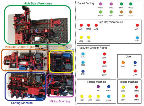
Figure 14.
Overview of components and sensors in the smart factory.
The smart factory is equipped with six different types of IoT sensors (cf. Figure 14), whose short labels and colors are summarized in Table 2.
Table 2.
IoT sensors of smart factory with short label and color.
In addition to the sensors of the smart factory, the scenario comprises four sensor types that measure the state of the environment (cf. Table 3).
Table 3.
Environment sensors of smart factory with short label and color.
In total, the smart factory has 34 sensors (see Figure 14), including 7 light barrier sensors that detect the interruption of a light beam, 10 limit switch sensors that are activated by the movement of a machine part or the presence of an object, 3 pressure sensors that measure the intake pressure, one temperature sensor that measures oven temperature, 4 encoder sensors that return the current motor position and one color sensor that detects the color of the workpiece. In addition, two vibration sensors, two brightness sensors, two humidity sensors and two air quality sensors are used to evaluate the workpiece condition.
Figure 15 illustrates a production process enabled by the smart factory. This example shows how we can model, setup, execute and monitor the IoT-driven BP based on the BPMNE4IoT framework. First of all, a white workpiece (WP) is transported to the transfer point of the high-bay warehouse. While delivering the workpiece, the vacuum gripper moves to the transfer point and waits until the condition of the IoT catch artifact evaluates it to be true. The Outside LB triggered catch artifact evaluates whether or not a light barrier is activated. The process may end, for example, if the condition is not satisfied within 120 s, e.g., due to network errors or defective sensors. The transport of the workpiece is activated by the Vacuum Gripper object artifact (cf. Section 5.2.4) and the oven is waiting for the arrival of the workpiece. Upon arrival, it is burned and then transported to the turntable for milling. Subsequently, the workpiece is transported to the sorting machine via a conveyor belt. After activating the light barrier, the color of the workpiece is automatically determined to sort it by color. Finally, the process terminates.
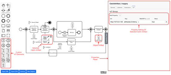
Figure 15.
Modeling and configuring IoT-driven process with the modeling tool.
The BPMS (cf. Section 5.3) manages the smart factory. First, the IoT-driven process must be modeled, accompanied by the configuration of the involved IoT devices. The modeling part of the BPMS is shown in Figure 15. It offers both the traditional BPMN 2.0 elements and the described IoT-specific artifacts and events (see Section 5.3). The process model depicted in Figure 15 comprises an object artifact, an IoT intermediate catch event, and an IoT intermediate catch artifact. In the properties panel (cf. Figure 15), the IoT condition (cf. Section 5.2.3) is configured. A sensor catch artifact and an object artifact are included in the process model from Figure 15. The IoT condition (cf. Section 5.3) of the selected catch artifact is configured inside the properties panel (cf. Figure 15). Note that one may add further conditions by using the plus symbol of the Add Property label for both the object artifact and the group artifacts. For the catch artifact, the following properties need to be specified: (i) an endpoint, (ii) an attribute that address the value from the response, and (iii) the condition to be met before continuing with the process. The created IoT-driven BP may be mapped to an XML file that can be imported by the IoT process engine. All information needed to execute the IoT-driven process is contained in this XML file.
Subsequently, the IoT-driven BP may be deployed to the execution engine of the BPMS, i.e., the IoT process engine. The latter creates and starts IoT-driven BP instances. An example of such an instance execution is shown in Figure 16. Each green colored element was successfully executed. A yellow overlay indicates the execution time and is displayed upon completion of the modeling element. The orange-colored elements are currently executed. In turn, the elements are highlighted in red when an error event occurs (e.g., a network issue or timeout during runtime). An execution log is shown on the right side, listing pertinent events (e.g., current progress and error messages).
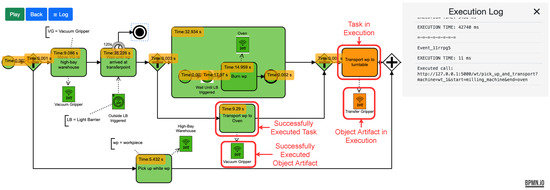
Figure 16.
IoT-driven smart factory process in execution.
6.2. Smart Home Scenario
Another domain, in which we evaluated BPMNE4IoT, is Smart Home. To keep the presented example simple, we focus on the sub-processes for controlling and monitoring the temperature and brightness of the smart office based on the BPMNE4IoT framework. Figure 17 shows the smart office, which is equipped with four different types of IoT sensors (cf. Table 4) and three different types of IoT actuators (cf. Table 5). In total, six sensors and three actuators are involved in the two sub-processes for controlling and monitoring the temperature and brightness.
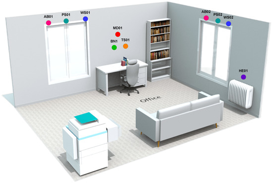
Figure 17.
Overview of the sensors and actuators in the smart office scenario.
Table 4.
IoT sensors used in Smart Office scenario with short label and color.
Table 5.
IoT actuators used in Smart Office scenario with short label and color.
In addition to the sensors installed in the smart office, the scenario comprises actuators to influence the physical environment (cf. Table 5).
The sub-process for controlling the brightness in the smart office is illustrated by Figure 18. This example shall demonstrate how such a controlling process can be modeled with BPMNE4IoT. The process is started as soon as the brightness exceeds 1000 Lux. In this case, the window blinds 1 and 2 are closed, controlling the respective actuators based on the IoT actuator artifact. The associated tasks are successfully completed as soon as the conditions specified by the IoT catch artifacts are met, i.e., position sensor “PS01 == 512” and position sensor “PS02 == 512”. While the window blinds are closed, the wind speed is continuously checked to determine whether it exceeds 20 km/h. If the latter applies, the corresponding blind motors are stopped using an IoT end event. Then, the process is aborted.
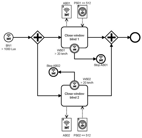
Figure 18.
Process to control the brightness in a smart office.
The sub-process for controlling the temperature in the smart office is illustrated by Figure 19. The process starts upon the detection of any movement. Afterwards, the temperature is queried using a smart IoT sensor. If the temperature is lower than 16 °C, the heating level is set to 100%. The heating level is set to 25% if the temperature lies between 16 °C and 22 °C. The heating level is set to 0% if the temperature exceeds 22 °C. Finally, the process ends.
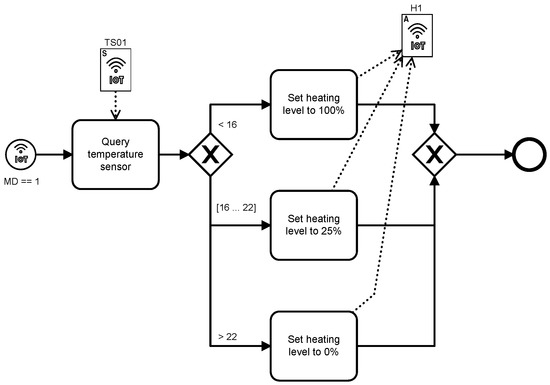
Figure 19.
Process to control the temperature in a smart office.
6.3. Conclusions from Prototype Evaluation
Based on the insights we gained when modeling, executing, monitoring and recording the process of the two scenarios, we can evaluate the feasibility of our framework. The modeling tool, which we extended with BPMNE4IoT, enables the non-ambiguous modeling of IoT participation (cf. Objective O1) in IoT-driven BPs by providing new artifact and event types. In addition, the properties panel (cf. Figure 15) may be used to configure the IoT properties and, thus, to separate concerns (cf. Objectives O2 and O8). Based on the BPMNE4IoT framework, we were able to model, execute, monitor and log IoT-driven smart factory processes as well as smart home processes, taking the intrinsic IoT characteristics of both scenarios into account. The implemented proof-of-concept prototype demonstrates that we were able to automate a smart factory process and to manufacture a product utilizing the BPMNE4IoT framework (cf. Objective O4). Although the presented scenarios work under lab conditions, it can be transferred to a real-world smart factory as only the scaling changes. In addition, Figure 16 shows the running smart factory process including the monitoring of the IoT-driven BP and a corresponding log. On one hand, we were able to show that the framework enables the real-time monitoring of IoT-driven processes (cf. Objective O5). On the other, we can generate an IoT-enhanced BP log, which can be used online, i.e., during process execution, and offline (cf. Objective O6).
7. End-User Study
In the Design Science Research Methodology, the evaluation step (cf. Figure 2—Step 5) shall observe and measure how well the designed artifact (cf. Section 5) supports a solution for the addressed problem (cf. Section 1.1). For this purpose, we conducted a controlled study with 30 participants to evaluate the proposed BPMN extension (BPMNE4IoT) with respect to user-friendliness, effectiveness, and workload (see RQ1). Study participants were asked to model the same IoT process and thereby compare IoT process modeling in BPMNE4IoT with BPMN 2.0. Note that we have compared our approach with the process modeling standard BPMN 2.0, as there is no agreed upon standard or tool for modeling IoT-driven BPs. Furthermore, the BPMN 2.0 standard is widely used and the participants are largely familiar with it. Moreover, comparing our framework with related works is complicated due to the fact that these works are often purely conceptual and the availability of modeling tools as open source software artifacts is limited. Specifically, we validated the following two hypotheses:
Hypothesis 1 (H1).
When modeling IoT-driven BPs with BPMNE4IoT, the workload decreases compared to the workload of BPMN 2.0 (cf. Objectives O3 and O7).
Hypothesis 2 (H2).
The time required to model a given process description with IoT characteristics into an IoT-driven BP model with BPMNE4IoT is less, compared to the time required with BPMN 2.0 (cf. Objectives O3 and O7).
7.1. Participants
Thirty participants (10 female and 20 male) aged between 22 and 32 years (M = 25.5, SD = 2.2) were recruited either via e-mail or within a learning platform to participate in the user study. Three participants were doctoral students at Ulm University, thirteen participants worked in the industry with a Bachelor’s degree, and the remaining fourteen participants were students (13 Master’s students in Computer Science and 1 student without a degree). All participants had some experiences with modeling business processes based on BPMN 2.0 (i.e., they participated in the BPM course or BPMN Modeling Lab at Ulm University); 6 of them were experienced with IoT as well. To avoid learning effects, we formed the following two groups G1 and G2 with 15 participants each.
- G1:
- Members of this group modeled the textually described process first with the Web-based BPMN 2.0 modeler BPMN.io (https://bpmn.io/, accessed on 18 January 2023). Subsequently, they performed the same task with the BPMNE4IoT modeler.
- G2:
- Members of this group first modeled the given process description with the BPMNE4IoT modeler. Subsequently, the same task was performed with BPMN.io.
7.2. Design and Instruments
The user study was performed as a within-subject design, where each participant was tested on each condition. Thereby, we measured the following two influencing variables for usability requirements [60]: (1) efficiency and (2) user acceptance [6]. Efficiency was measured as the time needed to complete the task successfully. In turn, user acceptance was measured with a NASTA-TLX questionnaire [61]. In a nutshell, the following instruments were applied to perform the experiment:
- A demographic questionnaire with questions about the educational degree, age and gender of the study participants, as well as their experience level with process modeling and IoT of the study participants.
- A task description for modeling the IoT-driven BP. This modeling shall be accomplished with (1) BPMNE4IoT and (2) standard BPMN (BPMN.io).
- A NASA-TLX [61] questionnaire that is used to capture the perceived mental, physical and temporal demand as well as performance, effort, and frustration on a 20-point scale with 1-point steps. The questionnaire is extended with a text field form to capture the start and completion times of modeling the process description [61].
7.3. Execution
To perform the study, we organized two workshops on two different days, each with 15 participants (G1 and G2). Both workshops were structured and performed identically, with the only difference being that in the second workshop the participants created the model of the given process description first with the BPMN extension (BPMNE4IoT) and then with BPMN 2.0 (cf. G1 and G2).
Directly before the study, we explained its procedure and goal to the participants. To ensure that the study participants reach a common ground, BPMN 2.0 was briefly introduced. Following this, BPMNE4IoT was presented. Finally, the study leader demonstrated both the BPMN.io and BPMNE4IoT modeling tools. After these introductions, the participants started modeling the process with the first tool and were guided by the study leader in case of major deviations, errors or questions. Each participant tracked the start and end time of the modeling task independently. Moreover, the study leader observed the participants during the study experiment and took notes regarding questions and the behavior of the study participants. Afterwards, the participants completed the NASA-TLX questionnaire. This procedure was repeated with the second tool.
7.4. Analysis of the Results
This section analyses the results of the user study. Section 7.4 provides a descriptive analysis, whereas Section 7.6 examines the study results with respect to their statistical significance.
7.4.1. Efficiency
We measured the efficiency as the task completion time required per approach. Modeling the given process description with BPMN.io took participants between 11 and 29 min (M = 17.6, SD = 5.6), whereas the time needed with the BPMNE4IoT modeler was between 4 to 10 min (M = 6.0, SD = 1.3). Figure 20 illustrates the results.
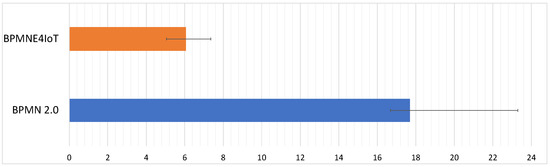
Figure 20.
Means and standard deviation of task completion time in minutes.
The results reveal a longer task completion for modeling the IoT process with BPMN.io. Most of the problems that emerge when modeling IoT-driven BPs with BPMN 2.0 were related to the use of the different modeling elements. As there are no IoT-specific modeling elements in BPMN 2.0, study participants were unsure how to model the IoT involvement. While some participants represented IoT involvement in terms of pools or lanes, others used different task types (i.e., service and script task) or event types (i.e., message and signal event). As another aspect noticed during the review of the models, some participants used business rule tasks to represent sensors and service tasks for actuators, while others used service tasks for both sensors and actuators. A third group used script tasks for modeling sensors and actuators. Due to the ambiguous BPMN modeling elements (cf. Figure 1: IoT-driven service task vs. non IoT-driven service task) and the fact that there are no IoT-specific modeling elements in BPMN 2.0, modeling IoT-driven BPs was more time consuming and complex. In BPMNE4IoT (cf. Section 5), there are specific elements (i.e., artifacts and events) for modeling sensors and actuators. As our BPMN extension (BPMNE4IoT) can explicitly represent specific IoT behavior (push and pull interaction and IoT conditions), the participants completed the given task faster compared to the use of BPMN 2.0. Note that the process models created by the study participants were checked for their semantic by two study guides. It was noticed that none of the study participants caused semantic errors in either BPMN or BPMNE4IoT. This can be explained with the fact that the participants already were experienced with modeling business processes in terms of BPMN 2.0. Moreover, the BPMNE4IoT extension conforms with BPMN 2.0. Consequently, we may conclude that BPMNE4IoT is more efficient than BPMN 2.0, i.e., less time is needed for modeling IoT-driven BPs compared to BPMN 2.0, which confirms Hypothesis H1.
7.4.2. Workload
After completing the modeling task with either one of the two languages (i.e., BPMN 2.0 vs. BPMNE4IoT), the participants were asked to fill out the NASA-TLX questionnaire to assess the individual task load perceived by them. Note that this questionnaire captures the perceived mental, physical and temporal demand as well as performance, effort and frustration on a 20-point scale, where the highest scores represent the worst results, i.e., these properties are rated on a scale from very low (0) to very high (20). The performance is rated on a scale ranging from very good (0) to very bad (20) [61]. Table 6 shows the obtained values (average (Avg), median (Med), standard deviation (SD), best result (Best), and worst result (Worst) columns). Figure 21 compares the TLX means and standard deviation of BPMNE4IoT and BPMN 2.0.
Table 6.
Results of the NASA-TLX questionnaire.
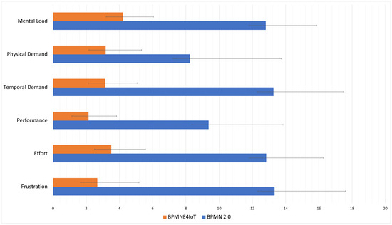
Figure 21.
Comparison of TLX means and standard deviation for modeling IoT-driven BPs.
Due to the higher complexity of representing the IoT involvement with BPMN 2.0, its limited suitability to represent IoT-specific behavior (e.g., continuous pull interaction), as well as the ambiguity of how to describe IoT aspects in process models, the overall task load and the individual factors are significantly higher for BPMN 2.0 than for BPMNE4IoT (cf. Table 6). As BPMN 2.0 is a general-purpose language that does not allow for the explicit modeling of IoT aspects, the study participants had to find workarounds to express the IoT devices and the desired process behavior. This task was overwhelming for study participants without experience in IoT-intensive domains (e.g., smart home, smart factory and smart health).
Although all participants had never applied BPMNE4IoT before and received only a short training of about 45 min, for the given task, the workload with BPMNE4IoT was lower than with BPMN 2.0. The better results for BPMNE4IoT can be explained with the ability of BPMNE4IoT to represent the IoT specifics (e.g., sensor pull interaction in a loop, asynchronicity and parallelism) and IoT behavior (e.g., IoT-driven business rules). Furthermore, BPMNE4IoT conforms to the BPMN standard, making the extension intuitive for BPMN process modelers. The results of the NASA-TLX (cf. Table 6 and Figure 21) reinforce these statements and confirm the Hypothesis H2.
7.5. Observations
We have derived additional findings from the observations and notes made by the study leader:
- When the study participants from both groups G1 and G2 were modeling the provided IoT-driven BP with BPMN 2.0, the study leader learned that the frustration level had been very high. This is noticeable as most study participants expressed their displeasure or disappointment about modeling the IoT-specific behavior with BPMN 2.0, which also affected their performance (cf. Figure 21). Most participants struggled to find proper workarounds to capture the involved IoT devices and IoT-specific process behavior. Moreover, they captured IoT involvement in terms of a black or white box pool. For communication purpose, the study participants used message events or tasks. While they applied service, script and message tasks for sensors and actuators, they either used conditional events or loops via XOR gateways for modeling the IoT conditions. Regarding the BPMNE4IoT modeling framework, it is noteworthy that none of the study participants used pools when modeling IoT-driven BPs, as unique modeling element exists for capturing sensor and actuator behaviors (cf. Section 5), meaning IoT involvement no longer needs to be represented by pools.
- Prior knowledge of BPMN 2.0 and the IoT domain was advantageous. Study participants with knowledge of IoT-driven BPs found it easier to model the given IoT-driven process according to the textual instructions. They also found it more accessible and required less time. Moreover, these study participants experienced a lower workload than others (cf. Table 6—BPMN Modeler Best value). This can be explained with the fact that study participants with prior knowledge in IoT-driven BPs already knew which BPMN 2.0 modeling elements can be used to express IoT participation (service, script, business rule and message tasks or events and pools) and IoT-specific behavior (e.g., continuous pull interaction and IoT conditions). Finally, study participants with prior knowledge of IoT-driven BPs in BPMN 2.0 reported a lower task load when using BPMNE4IoT than when using BPMN 2.0 despite their non-familiarity with BPMNE4IoT.
7.6. Inferential Statistics
The insights presented in Section 7.4 are merely based on descriptive differences. To evaluate whether the differences in the descriptive results reach statistical significance, independent-samples t-tests [62] were conducted to compare BPMNE4IoT and BPMN 2.0. All statistical tests performed were two-tailed and the significance value was set to p < 0.05. Table 7 summarizes the independent-samples t-tests.
Table 7.
Two-Sample T-Test Results for BPMNE4IoT and BPMN 2.0.
The results demonstarte that the participants had a statistically significant lower (t(47.4) = 13.1, p < 0.001) mental load when modeling IoT-driven BPs with BPMNE4IoT (M = 4.2, SD = 1.8) than when modeling them with BPMN 2.0 (M = 12.8, SD = 3.0). Physical demand was significantly lower (t(43.7) = 4.4, p < 0.001) when modeling IoT-driven BPs with BPMNE4IoT (M = 3.1, SD = 2.1) compared to BPMN 2.0 (M = 8.2, 5.5). Regarding temporal demand, study participants had a significantly higher load (t(40.4) = 37.1, p < 0.001) when modeling IoT-driven BP with BPMN 2.0 (M = 13.2, SD = 4.2) than with BPMNE4IoT (M = 3.1, SD = 1.9). The performance of modeling IoT-driven BPs is significantly better (t(37.1) = 8.2, p < 0.001) in BPMNE4IoT (M = 2.1, SD = 1.6) in comparison to BPMN 2.0 (M = 12.8, SD = 3.4). To model the given IoT-driven BP, study participants had to exert significantly more efforts (t(47.3) = 12.7, p < 0.001) when using BPMN 2.0 (M = 12.8, SD = 3.4) than when using BPMNE4IoT (M = 3.5, SD = 2.0). When modeling IoT-driven BPs with BPMN 2.0 (M = 13.3, SD = 4.2), study participants were more frustrated (t(46.8) = 11.7, p < 0.001) compared to the use of BPMNE4IoT (M = 2.6, SD = 2.5). Finally, participants require significantly less time (t(32.0) = 11.0, p < 0.001) to model the IoT-driven BP with BPMNE4IoT (M = 6.0, SD = 1.3) than when using BPMN 2.0 (M = 17.6, SD = 6.1). Overall, the independent-samples t-tests statistically confirms Hypotheses H1 and H2.
7.7. Threats to Validity
The results of our within-subject study need also be considered in the light of certain limitations. First, in a random participant group, it is always possible that there are users that are more experienced than others. Consequently, we faced the risk of an unexpected heterogeneity of the participants assigned to G1 and G2. Therefore, the final results could be influenced by the varying BPMN & IoT knowledge of the participants as well as by their domain knowledge. Although all the participants were randomly divided into two groups (i.e., G1 and G2), we attempted to minimize this risk by pre-training all participants to create a similar background as well as knowledge of the technologies required to perform the task. In this context, we provided a short tutorial on both the BPMN 2.0 basics and the BPMNE4IoT framework. In this tutorial, the participants learned how to apply BPMNE4IoT and BPMN 2.0, respectively. We provided the study participants with a more detailed explanation of the artifacts and events we had introduced for modeling IoT-driven business processes. Finally, we gave a introduction to both the BPMN.io and the BPMNE4IoT modeling tool.
Second, the two groups were built out of fourteen students, three doctoral students, and thirteen employees from the IT field (i.e., industry). Note that study participants with prior knowledge in modeling IoT-driven BPs with BPMN 2.0 still reported a lower task completion time when using BPMNE4IoT compared to the use of BPMN 2.0, even though they were using BPMNE4IoT for the first time. However, we acknowledge that further studies are needed with participants who are both process and IoT experts to generalize the results.
Third, the participants had to model an IoT-driven process based on a given process description. In future studies, participants should model multiple processes from different domains to verify whether the given process description or domain has an impact on the study outcome. However, we expect that BPMNE4IoT performs better than BPMN, as the involvement of IoT can be explicitly and unambiguously modeled using the introduced artifacts (cf. Section 5). Finally, process modeling is more straightforward when using BPMNE4IoT.
Finally, the study was conducted with a relatively limited sample size of 30 participants. Further studies with a larger number of participants are needed to generalize findings. Nevertheless, the obtained process models, combined with the NASA-TLX questionnaire and the required modeling time, provided promising initial results and insights into the workload and efficiency of modeling IoT-driven BPs with BPMNE4IoT.
7.8. Conclusions from User-Study
The results obtained in the within-subject study support Hypotheses H1 and H2. Thus, we may conclude that the proposed BPMN 2.0 extension (BPMNE4IoT) is more effective (i.e., less time is needed) and more intuitive (Objective O3) than BPMN 2.0 regarding the modeling of IoT-driven BPs (see H1). As pointed out in Section 7.4.1, participants with and without IoT experience were able to model the given IoT process description faster with BPMNE4IoT than with BPMN 2.0. In this context, no semantic modeling errors were introduced. Regarding H2, which focuses on the workload of users during the modeling of IoT-driven BPs, we showed that study participants experienced a lower workload when using BPMNE4IoT compared to BPMN 2.0 (see Section 7.4.2). This is remarkable, as most participants have had experiences with BPMN 2.0, whereas none of them had used BPMNE4IoT before.
As the findings obtained through the study are merely based on descriptive results, we conducted independent-samples t-tests to evaluate whether the differences described in the descriptive results reach statistical significance. The obtained results have demonstrated (cf. Table 7) that BPMNE4IoT performs significantly better than BPMN 2.0 in terms of efficiency and workload when modeling IoT-driven BPs. Overall, we can conclude that the proposed BPMN 2.0 extension for IoT-driven BPs is suitable.
8. Discussion
In this section, we discuss how the BPMNE4IoT framework for modeling, executing, monitoring and recording IoT-driven BPs addresses the derived research questions and objectives (cf. Section 1.1).
Regarding the modeling of IoT-driven BPs (RQ1), we identified a lack of support in both BPMN 2.0 and existing BPMN 2.0 extensions. To capture the IoT involvement and IoT characteristics in process models more explicitly, we extended the BPMN 2.0 metamodel with IoT-specific modeling elements and a corresponding notation (Objectives O1 and O2). The results of the user study further confirmed that the modeling of IoT-driven BPs with BPMNE4IoT leads to a positive user experience, takes less time, and decreases the workload in comparison to BPMN 2.0 (Objective O3).
The proposed BPMN 2.0 extension and the presented software architecture together form a holistic framework for modeling, executing, monitoring and recording IoT-driven BPs (RQ2). The modeling of IoT-driven BPs is enabled through extensions, which can represent IoT device involvement and IoT device behavior (cf. Objectives O1 and O2). The execution of the resulting IoT-driven BPs is enabled based on the implemented BPMS and its architecture (cf. Objective O4). In particular, the BPMS is able to interpret and execute the IoT-driven BP modeled in terms of the BPMNE4IoT extension. The monitoring of the corresponding process instances is enabled by the IoT Process Monitoring component, which is closely coupled with the engine, receiving continuous execution updates from it (cf. Objective O5). Both process execution data and IoT-specific execution data are stored in an IoT-enhanced event log (cf. Objective O6). Altogether, we have been able to demonstrate the modeling, execution, monitoring and recording of IoT-driven BPs from different domains.
To assist process engineers in modeling, executing and monitoring IoT-driven BPs (RQ3), we developed a tool that integrates the BPMNE4IoT extension (cf. Section 5.3). To keep the cognitive efforts low and to increase user acceptance, especially for non-experts, we implemented BPMNE4IoT in an already existing BPMN 2.0 modeler (bpmn.io). To increase usability, we have kept the configuration options for IoT devices to a minimum. Furthermore, process engineers are enabled to execute IoT-driven BPs with this tool. As the monitoring system is directly coupled with the execution engine, the process engineers receive direct feedback, e.g., at the occurrence of an error, non-reachability of IoT device, or defective IoT devices. Furthermore, an event log is available that contains more detailed information (cf. Objective O7). The tool was evaluated in two real-world scenarios (cf. Section 6). Moreover, we have separated the modeling of IoT-driven BPs from the specification of IoT devices in the tool. This allows BP experts to model processes without the need to deal with IoT-specific characteristics (cf. Objective O8).
As opposed to the existing approaches, we provide a holistic framework that supports all phases of the process lifecycle, i.e., the scope of this work is the modeling, execution, monitoring and logging of IoT-driven BPs. Note that we did not discuss other challenges such as IoT data security, robustness and reliability. Regarding the IoT data security, we made use of the standard mechanisms provided by the middleware, gateways, and IoT devices. The current approach enables the monitoring of defective and unreachable IoT devices. However, the handling of such failures has not been considered.
9. Summary and Outlook
In this work, we presented a holistic framework for modeling, executing, monitoring and recording IoT-driven BPs. Following the Design Science Research Methodology, we identified a missing integrated support of these tasks. Then, we studied existing approaches to evaluate their suitability with respect to such an integrated lifecycle support for IoT-driven BPs. As drawbacks of the studied approaches, they do not support the intrinsic IoT characteristics, are described only theoretically, or focused on extending BPMN for modeling and do not support the execution, recording and monitoring of IoT-driven BPs. Based on these insights, we derived research questions, which we then refined by formulating several objectives to improve the lifecycle support of IoT-driven BPs. Regarding the modeling and monitoring phase, we extended the BPMN 2.0 metamodel with IoT-specific artifacts and events, resulting in BPMNE4IoT. To be able to execute and monitor the BP created with BPMNE4IoT, we defined an appropriate architecture and implemented an IoT-aware BPMS. Together, they enable a holistic framework for IoT-driven BPs. Moreover, we extended a common BPMN 2.0 modeler with BPMNE4IoT and, thus, support process engineers with a modeling environment with which they are familiar. Based on the proof-of-concept evaluation and the application of the resulting prototype to the smart production and smart home, we could demonstrate the applicability of the framework and its concepts in different domains. Altogether, the prototype evaluation has demonstrated that we are able to model, execute, monitor and log IoT-driven BPs. The results of the user study confirmed that the use of BPMNE4IoT has led to an increased usability and user experience (i.e., better task completion times, positive feelings and lower workload) compared the modeling of IoT-driven BPs with BPMN 2.0.
In future work, we want to perform further experiments and studies to assess the completeness and domain independence of the BPMNE4IoT framework. So far, we have compared BPMNE4IoT with the de-facto process modeling standard BPMN 2.0, as there is no defined standard or tool for modeling, executing, monitoring and recording IoT-driven BPs. Nevertheless, in future work we want to compare BPMNE4IoT with other approaches regarding modeling, usability, acceptance and user experience. Finally, we want to review how we can complement our framework with state-of-the-art IoT security mechanisms.
Author Contributions
Y.K. and F.G. designed the concept, conceived and wrote the paper; Y.K. designed the methodology; Y.K. and M.W. used static and mathematical techniques to analyze the study data; M.R. corrected and supervised this work. All authors have read and agreed to the published version of the manuscript.
Funding
This work was funded by the Deutsche Forschungsgemeinschaft (DFG, German Research Foundation) under project number 449721677.
Data Availability Statement
There is no relevant external data. All data is contained within the article.
Conflicts of Interest
The authors declare no conflict of interest.
References
- Chang, C.; Srirama, S.N.; Buyya, R. Mobile Cloud Business Process Management System for the Internet of Things: A Survey. ACM Comput. Surv. 2016, 49, 1–42. [Google Scholar] [CrossRef]
- Bayomie, D.; Revoredo, K.; Bachhofner, S.; Kurniawan, K.; Kiesling, E.; Mendling, J. Analyzing Manufacturing Process By Enabling Process Mining on Sensor Data. In Proceedings of the PoEM Workshops, London, UK, 23–25 November 2022. [Google Scholar]
- Ashton, K. That ‘internet of things’ thing. RFID J. 2009, 22, 97–114. [Google Scholar]
- Kirikkayis, Y.; Gallik, F.; Reichert, M. Towards a Comprehensive BPMN Extension for Modeling IoT-Aware Processes in Business Process Models. In Proceedings of the Research Challenges in Information Science, Barcelona, Spain, 17–20 May 2022; Springer Int Publishing: Cham, Switzerland, 2022; pp. 711–718. [Google Scholar]
- Bauer, M.; Bui, N.; De Loof, J.; Magerkurth, C.; Nettsträter, A.; Stefa, J.; Walewski, J.W. IoT reference model. In Enabling Things to Talk; Springer: Berlin/Heidelberg, Germany, 2013; pp. 113–162. [Google Scholar]
- Valderas, P.; Torres, V.; Serral, E. Modelling and executing IoT-enhanced business processes through BPMN and microservices. J. Syst. Softw. 2022, 184, 111139. [Google Scholar] [CrossRef]
- Janiesch, C.; Koschmider, A.; Mecella, M.; Weber, B.; Burattin, A.; Di Ciccio, C.; Fortino, G.; Gal, A.; Kannengiesser, U.; Leotta, F.; et al. The Internet of Things Meets Business Process Management: A Manifesto. IEEE Syst. Man Cybern. Mag. 2020, 6, 34–44. [Google Scholar] [CrossRef]
- Valero, C.; Ruiz-Altisent, M. Design Guidelines for a Quality Assessment System of Fresh Fruits in Fruit Centers and Hypermarkets; International Commission of Agricultural Engineering: Liege, Belgium, 2000; Volume 2. [Google Scholar]
- Kirikkayis, Y.; Gallik, F.; Reichert, M. Modeling, Executing and Monitoring IoT-Driven Business Rules with BPMN and DMN: Current Support and Challenges. In Proceedings of the Enterprise Design, Operations, and Computing: 26th International Conference, EDOC 2022, Bozen-Bolzano, Italy, 3–7 October 2022; Springer: Berlin/Heidelberg, Germany, 2022; pp. 111–127. [Google Scholar]
- Valderas, P.; Torres, V.; Serral, E. Towards an Interdisciplinary Development of IoT-Enhanced Business Processes. Bus. Inf. Syst. Eng. 2022, 65, 25–48. [Google Scholar] [CrossRef]
- Kirikkayis, Y.; Gallik, F.; Reichert, M. A Holistic Framework for IoT-Aware Business Processes. In Proceedings of the Business Process Management Workshops, Munster, Germany, 11–16 September 2022. [Google Scholar]
- Seiger, R.; Kühn, R.; Korzetz, M.; Aßmann, U. HoloFlows: Modelling of processes for the Internet of Things in mixed reality. Softw. Syst. Model. 2021, 20, 1465–1489. [Google Scholar] [CrossRef]
- Rose, K.; Eldridge, S.; Chapin, L. The internet of things: An overview. Internet Soc. 2015, 80, 1–50. [Google Scholar]
- Dertien, E.; Regtien, P.P. Sensors for Mechatronics; Elsevier: Amsterdam, The Netherlands, 2018. [Google Scholar]
- Fielding, R.T.; Taylor, R.N. Principled design of the modern web architecture. ACM Trans. Internet Technol. (TOIT) 2002, 2, 115–150. [Google Scholar] [CrossRef]
- Martin-Flatin, J.P. Push vs. pull in web-based network management. In Integrated Network Management VI. Distributed Management for the Networked Millennium, Proceedings of the Sixth IFIP/IEEE International Symposium on Integrated Network Management, Bordeaux, France, 18–20 May 2021; (Cat. No. 99EX302); IEEE: Piscataway, NJ, USA, 1999; pp. 3–18. [Google Scholar]
- C. Sofia, R.; M. Mendes, P. An overview on push-based communication models for information-centric networking. Future Internet 2019, 11, 74. [Google Scholar] [CrossRef]
- Weske, M. Business Process Management Architectures; Springer: Berlin/Heidelberg, Germany, 2007. [Google Scholar]
- Dumas, M.; La Rosa, M.; Mendling, J.; Reijers, H.A.; Dumas, M.; La Rosa, M.; Mendling, J.; Reijers, H.A. Fundamentals of Business Process Management; Springer: Berlin/Heidelberg, Germany, 2013; Volume 1. [Google Scholar]
- Model, B.P. Notation (BPMN) Version 2.0; OMG Specification, Object Management Group: Milford, MA, USA, 2011. [Google Scholar]
- Seiger, R.; Malburg, L.; Weber, B.; Bergmann, R. Integrating process management and event processing in smart factories: A systems architecture and use cases. J. Manuf. Syst. 2022, 63, 575–592. [Google Scholar] [CrossRef]
- Schönig, S.; Ackermann, L.; Jablonski, S.; Ermer, A. IoT meets BPM: A bidirectional communication architecture for IoT-aware process execution. Softw. Syst. Model. 2020, 19, 1443–1459. [Google Scholar] [CrossRef]
- Peffers, K.; Tuunanen, T.; Rothenberger, M.; Chatterjee, S. A design science research methodology for information systems research. J. Manag. Inf. Syst. 2007, 24, 45–77. [Google Scholar] [CrossRef]
- Gallik, F.; Kirikkayis, Y.; Reichert, M. Modeling, Executing and Monitoring IoT-Aware Processes with BPM Technology. In Proceedings of the 2022 International Conference on Service Science (ICSS), Zhuhai, China, 13–15 May 2022; pp. 96–103. [Google Scholar]
- Kirikkayis, Y.; Gallik, F.; Reichert, M. Lifecycle Support for IoT-Driven Business Rules. In Proceedings of the CENTERIS 2022, Lisboa, Portugal, 9–11 November 2022; Elsevier: Amsterdam, The Netherlands, 2022. [Google Scholar]
- Yousfi, A.; Bauer, C.; Saidi, R.; Dey, A. uBPMN: A BPMN extension for modeling ubiquitous business processes. Inf. Softw. Technol. 2016, 74, 55–68. [Google Scholar] [CrossRef]
- Seiger, R.; Assmann, U.; Huber, S. A case study for workflow-based automation in the internet of things. In Proceedings of the 2018 IEEE International Conference on Software Architecture Companion (ICSA-C), Seattle, WA, USA, 30 April–4 May 2018; IEEE: Piscataway, NJ, USA, 2018; pp. 11–18. [Google Scholar]
- Seiger, R.; Huber, S.; Schlegel, T. Toward an execution system for self-healing workflows in cyber-physical systems. Softw. Syst. Model. 2018, 17, 551–572. [Google Scholar] [CrossRef]
- Braun, R.; Schlieter, H.; Burwitz, M.; Esswein, W. BPMN4CP: Design and implementation of a BPMN extension for clinical pathways. In Proceedings of the 2014 IEEE International Conference on Bioinformatics and Biomedicine (BIBM), Belfast, UK, 2–5 November 2014; IEEE: Piscataway, NJ, USA, 2014; pp. 9–16. [Google Scholar]
- Hasić, F.; Asensio, E.S. Executing IoT Processes in BPMN 2.0: Current Support and Remaining Challenges. In Proceedings of the 2019 13th International Conference on Research Challenges in Information Science (RCIS), Brussels, Belgium, 29–31 May 2019; pp. 1–6. [Google Scholar]
- Celestrini, J.R.; Rocha, R.N.; Saleme, E.B.; Santos, C.A.; Filho, J.G.P.; Andreão, R.V. An architecture and its tools for integrating IoT and BPMN in agriculture scenarios. In Proceedings of the 34th ACM/SIGAPP Symposium on Applied Computing, Limassol, Cyprus, 8–12 April 2019; pp. 824–831. [Google Scholar]
- Bertrand, Y.; De Weerdt, J.; Serral, E. A Bridging Model for Process Mining and IoT. In Proceedings of the International Conference on Process Mining, Munster, Germany, 11–16 September 2022; pp. 98–110. [Google Scholar]
- Seiger, R.; Zerbato, F.; Burattin, A.; García-Bañuelos, L.; Weber, B. Towards iot-driven process event log generation for conformance checking in smart factories. In Proceedings of the 2020 IEEE 24th International Enterprise Distributed Object Computing Workshop (EDOCW), Eindhoven, The Netherlands, 5–8 October 2020; IEEE: Piscataway, NJ, USA, 2020; pp. 20–26. [Google Scholar]
- Malburg, L.; Grüger, J.; Bergmann, R. An IoT-Enriched Event Log for Process Mining in Smart Factories. arXiv 2022, arXiv:2209.02702. [Google Scholar]
- Compagnucci, I.; Corradini, F.; Fornari, F.; Polini, A.; Re, B.; Tiezzi, F. A systematic literature review on IoT-aware business process modeling views, requirements and notations. Softw. Syst. Model. 2022, 1–36. [Google Scholar] [CrossRef]
- Torres, V.; Serral, E.; Valderas, P.; Pelechano, V.; Grefen, P. Modeling of IoT devices in Business Processes: A Systematic Mapping Study. In Proceedings of the 2020 IEEE 22nd Conference on Business Informatics (CBI), Antwerp, Belgium, 22–24 June 2020; Volume 1, pp. 221–230. [Google Scholar]
- Caracaş, A.; Kramp, T. On the expressiveness of BPMN for modeling wireless sensor networks applications. In Proceedings of the International Workshop on Business Process Modeling Notation, Lucerne, Switzerland, 21–22 November 2011; Springer: Berlin/Heidelberg, Germany, 2011; pp. 16–30. [Google Scholar]
- Caracaş, A.; Bernauer, A. Compiling business process models for sensor networks. In Proceedings of the 2011 International Conference on Distributed Computing in Sensor Systems and Workshops (DCOSS), Barcelona, Spain, 27–29 June 2011; IEEE: Piscataway, NJ, USA, 2011; pp. 1–8. [Google Scholar]
- Caracas, A. From business process models to pervasive applications: Synchronization and optimization. In Proceedings of the 2012 IEEE International Conference on Pervasive Computing and Communications Workshops, Lugano, Switzerland, 19–23 March 2012; IEEE: Piscataway, NJ, USA, 2012; pp. 320–325. [Google Scholar]
- Baresi, L.; Meroni, G.; Plebani, P. A GSM-based approach for monitoring cross-organization business processes using smart objects. In Proceedings of the International Conference on Business Process Management, Rome, Italy, 6–10 September 2021; Springer: Berlin/Heidelberg, Germany, 2016; pp. 389–400. [Google Scholar]
- Domingos, D.; Martins, F. Using BPMN to model Internet of Things behavior within business process. Int. J. Inf. Syst. Proj. Manag. 2017, 5, 39–51. [Google Scholar] [CrossRef]
- Meroni, G.; Baresi, L.; Montali, M.; Plebani, P. Multi-party business process compliance monitoring through IoT-enabled artifacts. Inf. Syst. 2018, 73, 61–78. [Google Scholar] [CrossRef]
- Friedow, C.; Völker, M.; Hewelt, M. Integrating IoT devices into business processes. In Proceedings of the International conference on advanced information systems engineering, Melbourne, VIC, Australia, 28 June–2 July 2021; Springer: Berlin/Heidelberg, Germany, 2018; pp. 265–277. [Google Scholar]
- Mass, J.; Chang, C.; Srirama, S.N. Wiseware: A device-to-device-based business process management system for industrial internet of things. In Proceedings of the 2016 IEEE International Conference on Internet of Things (iThings) and IEEE Green Computing and Communications (GreenCom) and IEEE Cyber, Physical and Social Computing (CPSCom) and IEEE Smart Data (SmartData), Espoo, Finland, 22–25 August 2022; IEEE: Piscataway, NJ, USA, 2016; pp. 269–275. [Google Scholar]
- Agarwal, P.; Alam, M. Investigating IoT Middleware Platforms for Smart Application Development. In Proceedings of the Smart Cities—Opportunities and Challenges; Ahmed, S., Abbas, S.M., Zia, H., Eds.; Springer: Singapore, 2020; pp. 231–244. [Google Scholar]
- Appel, S.; Kleber, P.; Frischbier, S.; Freudenreich, T.; Buchmann, A. Modeling and execution of event stream processing in business processes. Inf. Syst. 2014, 46, 140–156. [Google Scholar] [CrossRef]
- Sungur, C.T.; Spiess, P.; Oertel, N.; Kopp, O. Extending bpmn for wireless sensor networks. In Proceedings of the 2013 IEEE 15th Conference on Business Informatics, Vienna, Austria, 15–18 July 2013; IEEE: Piscataway, NJ, USA, 2013; pp. 109–116. [Google Scholar]
- Meyer, S.; Ruppen, A.; Magerkurth, C. Internet of things-aware process modeling: Integrating IoT devices as business process resources. In Proceedings of the International Conference on advanced Information Systems Engineering, Melbourne, VIC, Australia, 28 June–2 July 2013; Springer: Berlin/Heidelberg, Germany, 2013; pp. 84–98. [Google Scholar]
- Meyer, S.; Ruppen, A.; Hilty, L. The things of the internet of things in BPMN. In Proceedings of the International Conference on Advanced Information Systems Engineering, Melbourne, VIC, Australia, 28 June–2 July 2013; Springer: Berlin/Heidelberg, Germany, 2015; pp. 285–297. [Google Scholar]
- Sperner, K.; Meyer, S.; Magerkurth, C. Introducing entity-based concepts to business process modeling. In Proceedings of the International Workshop on Business Process Modeling Notation, Lucerne, Switzerland, 21–22 November 2011; Springer: Berlin/Heidelberg, Germany, 2011; pp. 166–171. [Google Scholar]
- Park, M.; Kim, H.; Ahn, H.; Kim, K.P. An IoT-aware workflow model designer for smart alarm service about companion animal health check. In Proceedings of the 2018 20th International Conference on Advanced Communication Technology (ICACT), Chuncheon, Republic of Korea, 11–14 February 2018; IEEE: Piscataway, NJ, USA, 2018; pp. 728–731. [Google Scholar]
- Cheng, Y.; Zhao, S.; Cheng, B.; Chen, X.; Chen, J. Modeling and deploying IoT-aware business process applications in sensor networks. Sensors 2018, 19, 111. [Google Scholar] [CrossRef]
- Graja, I.; Kallel, S.; Guermouche, N.; Kacem, A.H. BPMN4CPS: A BPMN extension for modeling cyber-physical systems. In Proceedings of the 2016 IEEE 25th International Conference on Enabling Technologies: Infrastructure for Collaborative Enterprises (WETICE), Paris, France, 13–15 June 2016; IEEE: Piscataway, NJ, USA, 2016; pp. 152–157. [Google Scholar]
- Kozel, T. BPMN mobilisation. In Proceedings of the European Conference of Systems, and European Conference of Circuits Technology and Devices, and European Conference of Communications, and European Conference on Computer Science, Stevens Point, WI, USA, 30 November–2 December 2010; pp. 307–310. [Google Scholar]
- Petrasch, R.; Hentschke, R. Process modeling for industry 4.0 applications: Towards an industry 4.0 process modeling language and method. In Proceedings of the 2016 13th International Joint Conference on Computer Science and Software Engineering (JCSSE), Khon Kaen, Thailand, 13–15 July 2016; IEEE: Piscataway, NJ, USA, 2016; pp. 1–5. [Google Scholar]
- Petrasch, R.; Hentschke, R. Towards an Internet-of-Things-aware process modeling method. In Proceedings of the 2nd Management Innovation Technology International Conference (MITiCON2015), Bangkok, Thailand, 16–18 November 2015; pp. 168–172. [Google Scholar]
- Braun, R.; Esswein, W. Towards an integrated method for the extension of mof-based modeling languages. In Model and Data Engineering; Springer: Berlin/Heidelberg, Germany, 2015; pp. 103–115. [Google Scholar]
- Rosen, R.; von Wichert, G.; Lo, G.; Bettenhausen, K.D. About The Importance of Autonomy and Digital Twins for the Future of Manufacturing. In Proceedings of the 15th IFAC Symposium onInformation Control Problems in Manufacturing, Ottawa, ON, Canada, 11–13 May 2015; Volume 48, pp. 567–572. [Google Scholar]
- Grüger, J.; Malburg, L.; Mangler, J.; Bertrand, Y.; Rinderle-Ma, S.; Bergmann, R.; Asensio, E.S. SensorStream: An XES Extension for Enriching Event Logs with IoT-Sensor Data. arXiv 2022, arXiv:2206.11392. [Google Scholar]
- ISO Standard 9241-11:1998; Ergonomic Requirements for Office Work with Visual Display Terminals (vdts)–Part 11: Guidance on Usability. International Organization for Standardization: Geneva, Switzerland, 1998; Volume 55.
- Hart, S.G.; Staveland, L.E. Development of NASA-TLX (Task Load Index): Results of Empirical and Theoretical Research. Adv. Psychol. 1988, 52, 139–183. [Google Scholar]
- Ross, A.; Willson, V.L. Independent Samples T-Test. In Basic and Advanced Statistical Tests: Writing Results Sections and Creating Tables and Figures; Sense Publishers: Rotterdam, The Netherlands, 2017; pp. 13–16. [Google Scholar]
Disclaimer/Publisher’s Note: The statements, opinions and data contained in all publications are solely those of the individual author(s) and contributor(s) and not of MDPI and/or the editor(s). MDPI and/or the editor(s) disclaim responsibility for any injury to people or property resulting from any ideas, methods, instructions or products referred to in the content. |
© 2023 by the authors. Licensee MDPI, Basel, Switzerland. This article is an open access article distributed under the terms and conditions of the Creative Commons Attribution (CC BY) license (https://creativecommons.org/licenses/by/4.0/).