1. Introduction
Transportation has always been crucial in human society. It connects people, allows access to essential services and promotes prosperity. However, the growing number of vehicles [
1] has led to concerns about road traffic and safety. Despite stricter European road safety regulations [
2], accidents persist, leading to fatalities. Moreover, increased road traffic has resulted in congestion, higher gas emissions and decreased air quality [
3]. The 2018 global status report on road safety [
1] from the World Health Organisation (WHO) alerts that the number of road traffic deaths worldwide remains unacceptably high, with 1.35 million people dying each year—the eighth leading cause of death for people of all ages and the number one cause for children and young adults.
Considering these circumstances, finding strategies to make transportation safer becomes essential. In the last few years, progress has been made in the field of cooperative intelligent transport systems (C-ITS) [
4], particularly in the architecture of solutions that enable vehicles to exchange information with each other (V2V), the road infrastructure (V2I), and with pedestrians (V2P), being therefore known as vehicle-to-everything (V2X). The main C-ITS goal is to enable communication and information exchange among road elements, providing cooperation and, thus, increasing safety, mobility and sustainability [
5].
Despite the potential benefits, C-ITS/V2X communications are inherently open. This openness creates vulnerabilities [
6] that attackers can exploit, representing a significant threat to all road users, as security failures can lead to privacy violations or even fatalities. These security and privacy challenges must be addressed to ensure that road safety is not compromised [
7]. According to Serban et al. [
8], “Security plays a crucial role in cooperative applications because a security breach can easily lead to human casualties”. Moreover, C-ITS relies heavily on communication between vehicles that have the necessary equipment installed. This issue is also raised by Yoshizawa et al. [
9], where it is referred that, although in the European Norm (EN) 302 665 (V1.1.1) [
10], the European Telecommunications Standards Institute (ETSI) has defined handheld devices as one of the types of ITS stations, subsequent ETSI specifications have mainly focused on a vehicle-centric view. In this regard, a high fatality rate is correlated with soft-mobility road users [
1]. Therefore, in the development of C-ITS-based systems, it is essential to broaden the perspective beyond connected vehicles, also considering the needs of soft-mobility users (e.g., cyclists) and legacy vehicles that do not have the required equipment—the on-board units (OBUs).
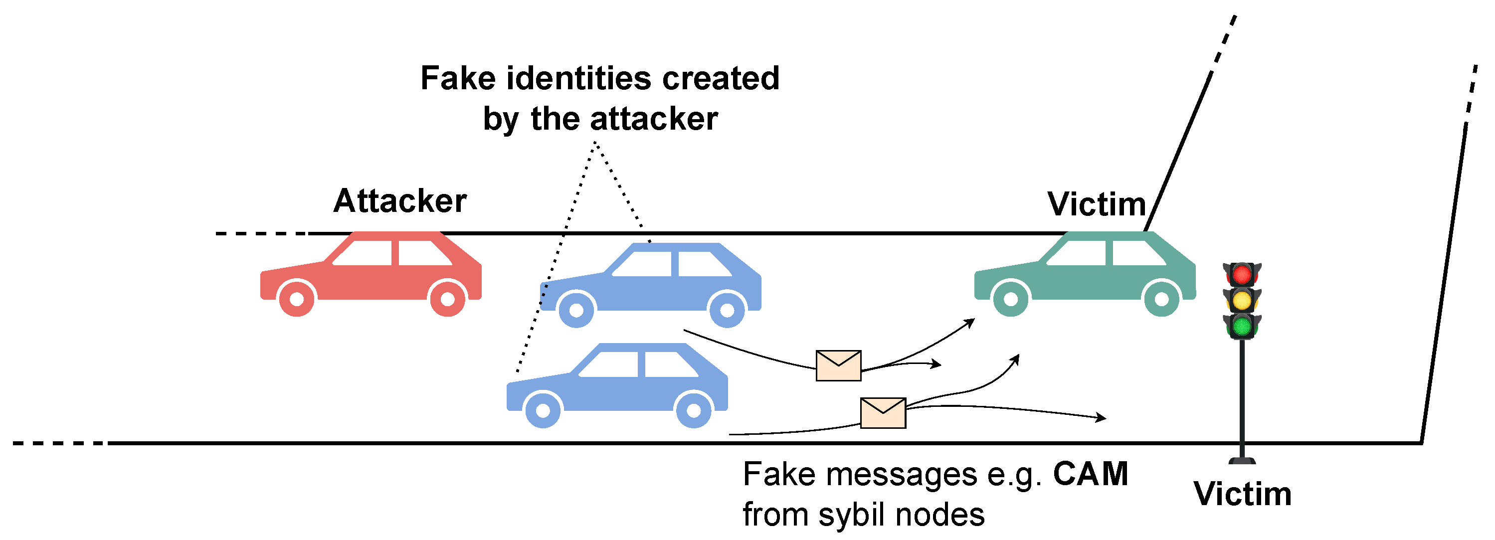
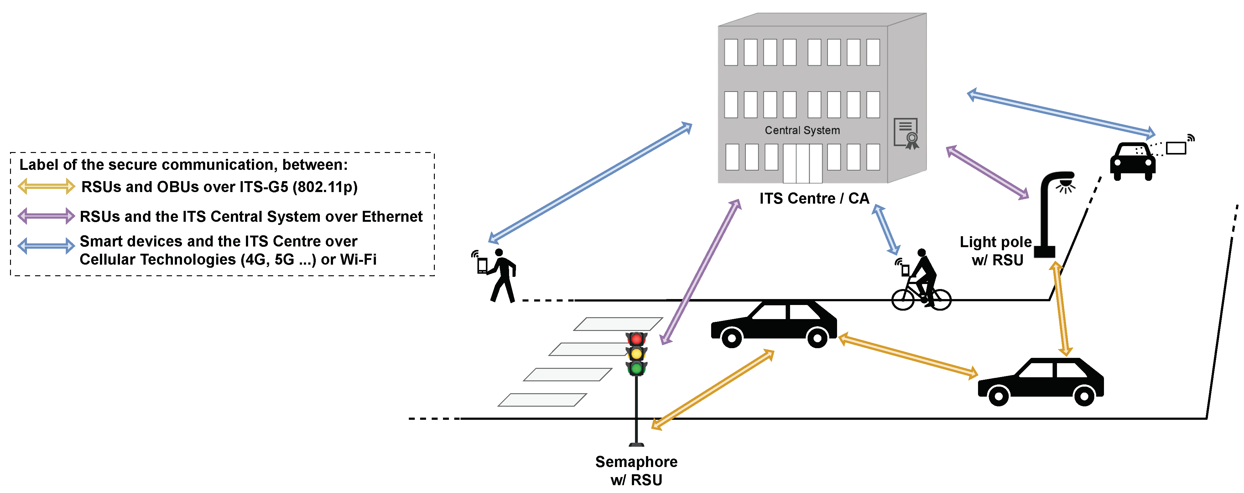
To illustrate these issues, some possible scenarios are described. An attacker could perform a Sybil attack, as illustrated in
Figure 1, where he claims the existence of non-existing vehicles at multiple locations [
7], creating confusion and disrupting communication. This could lead to inaccurate traffic information (e.g., fake congestion), which can cause misinformed decision-making by drivers.
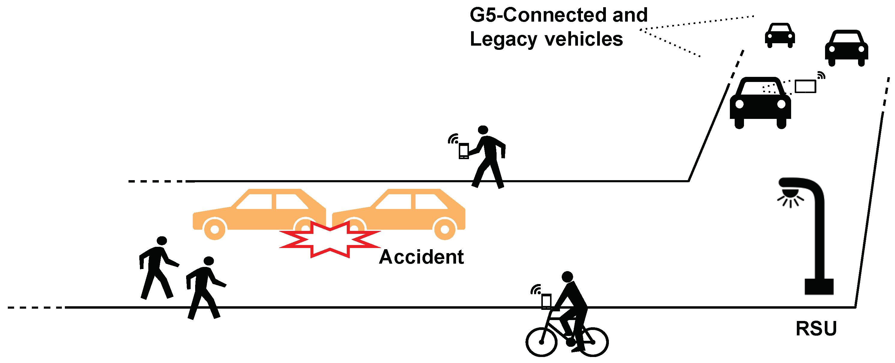
The situation depicted in
Figure 2 exemplifies why it is beneficial to include soft-mobility users and legacy vehicles in the C-ITS ecosystem. In this scenario, an accident occurred, and vehicles (legacy and G5-connected) were approaching. The lack of information about the situation makes it unpredictable and unsafe. The cyclist and the pedestrians present could securely notify ITS central systems. Information about this event could then be disseminated to connected vehicles.
To address previous issues, this work develops a proof-of-concept approach that introduces security guarantees within a C-ITS ecosystem while accommodating soft-mobility users and legacy vehicles. Additionally, this research intends to evaluate and compare the security protocols proposed in the literature using real equipment. Emphasis is also given to assessing how the security protocols affect performance. Lastly, this study measures the performance cost of incorporating soft-mobility users and legacy vehicles within a realistic testing environment. To accomplish these goals, this work builds and assesses a system that employs a security protocol in a C-ITS environment while operating within a hybrid network, combining intelligent transport systems operating in 5.9 GHz (ITS-G5) and cellular technologies. Thus, the proposed approach integrates G5-connected ITS stations and soft-mobility users connected through their smartphones via cellular networks, such as the fifth- and sixth-generation (5G and 6G) [
11,
12]. Two security protocols, DLAPP [
13] and MFSPV [
14], were implemented using hardware equipment—OBUs, roadside units (RSUs) and smartphones. An application was developed for each of these computing environments. These applications allow sending and receiving/verifying protected messages using a protocol.
Viewing through a high-level model, the proposed approach and subsequent experimental environment are embedded in the context of edge computing (EC) and fog computing (FC) paradigms [
15]. Devices, such as smartphones, OBUs found in vehicles and RSUs along the road infrastructure, act as communication devices [
16] that operate at the edge of the hybrid network. They process data in their local applications, providing low latency and faster response [
17]. Lastly, computational, transmission and end-to-end latency were used to assess the system’s performance. Our primary contributions are:
Development and assessment of a novel approach that employs a security protocol in a C-ITS hybrid environment by combining ITS-G5 and radio-mobile networks;
Extend the literature by going beyond the traditional focus on connected vehicles to include soft mobility users and legacy vehicles in C-ITS;
Assessing the effectiveness of security protocols (DLAPP [
13] and MFSPV [
14]), thus bridging the gap between theory/simulation and real-world implementations;
Enrichment of the literature’s information regarding the implementation of security protocols in real ITS equipment (OBUs and RSUs).
This paper is organised as follows. First,
Section 2 reviews the existing concepts and research related to this problem, including the implemented security protocols.
Section 3 presents the proposed approach and its development.
Section 4 analyses and reports the conducted experimental evaluation. Finally,
Section 5 concludes the document by summarising the developed work, main remarks and possible future work.
3. Proposed Approach
This section presents the approach proposed to achieve the outlined objectives. First, a high-level overview of the approach is given.
Section 3.1 shows greater detail of its architecture. Finally,
Section 3.2 provides insight into the implementation.
This study aims to build and assess a proof-of-concept system that employs a security protocol in a C-ITS hybrid environment. Thus, the system should enable G5-connected ITS stations to send protected messages that can be received and verified by other ITS stations and mobile applications (apps) and vice versa. As for security, DLAPP [
13] and MFSPV [
14] protocols are implemented, evaluated and compared using real equipment. To illustrate the proposed approach to achieve these goals, a simplified depiction is provided in
Figure 6.
A soft-mobility user message (e.g., CAM) is transmitted through a mobile app to the ITS centre, which then relays it to road infrastructures, such as semaphores equipped with RSUs. These RSUs disseminate the messages over the G5 network to vehicles equipped with OBUs as they pass by. Conversely, messages initially sent via G5 are routed through RSUs to the ITS centre, which distributes these messages to mobile apps. This approach establishes a bi-directional communication channel, bridging the G5 and cellular networks. Furthermore, within the hybrid C-ITS ecosystem, every type of node—smartphones, OBUs, and RSUs—is required to implement the security protocols MFSPV [
14] and DLAPP [
13], so one of them can be used, thus enabling information sharing among road users with security guarantees.
3.1. Proposed Architecture
In this section, the architecture of the proposed approach and the elements that constitute it will be described.
3.1.1. Domains and Entities
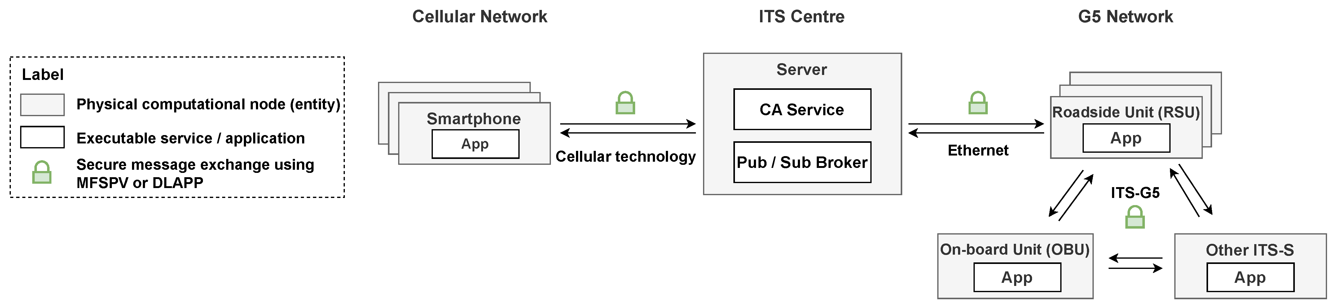
Figure 7 presents a more detailed perspective of
Figure 6. The proposed approach can be separated into three domains: cellular network, ITS centre and ITS-G5 network.
The padlock label in
Figure 7 indicates a secure exchange of messages using MFSPV [
14] or DLAPP [
13]. Therefore, each application must implement these protocols, as they will introduce security guarantees. Note that during message exchanges, only one protocol is used. The configuration of which protocol to use occurs at the initialisation of each app.
3.1.2. Message Exchange Scenarios
The scenarios contemplated for exchanging messages with security guarantees are illustrated in
Figure 8,
Figure 9 and
Figure 10. These message exchanges assume the configuration of a security protocol (MFSPV or DLAPP) to protect and deprotect (verify) a message. The numerical sequence in each figure represent the order of actions performed.
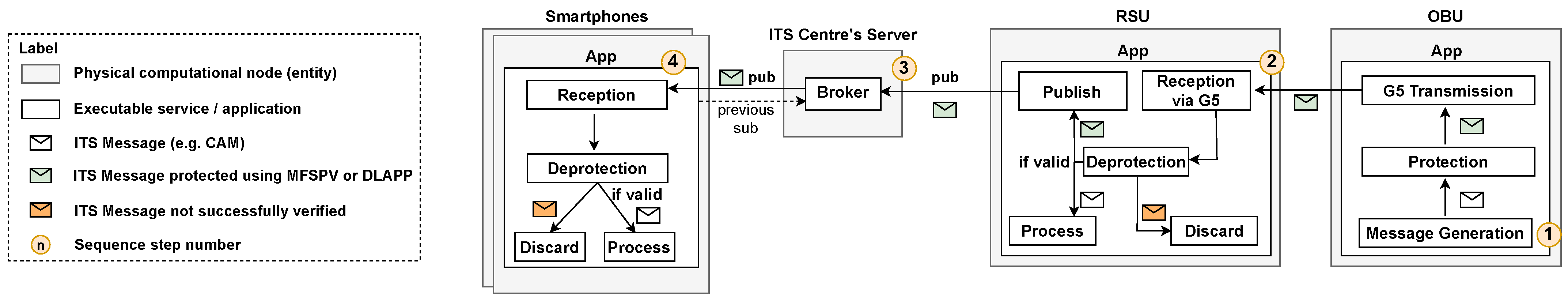
Firstly, the sequential flow when the OBU generates a message in the G5 network is described in
Figure 8. The step-by-step is as follows: (1) The OBU generates the ITS message, protects it with the configured security protocol and transmits it via G5. (2) An RSU receives the message and validates it. If the message is valid, the RSU processes and publishes it in the broker. Otherwise, it discards it. (3) The broker receives the message and sends it to all interested consumers. (4) Each interested smartphone receives and verifies the message. If it is successfully verified, then it is processed.
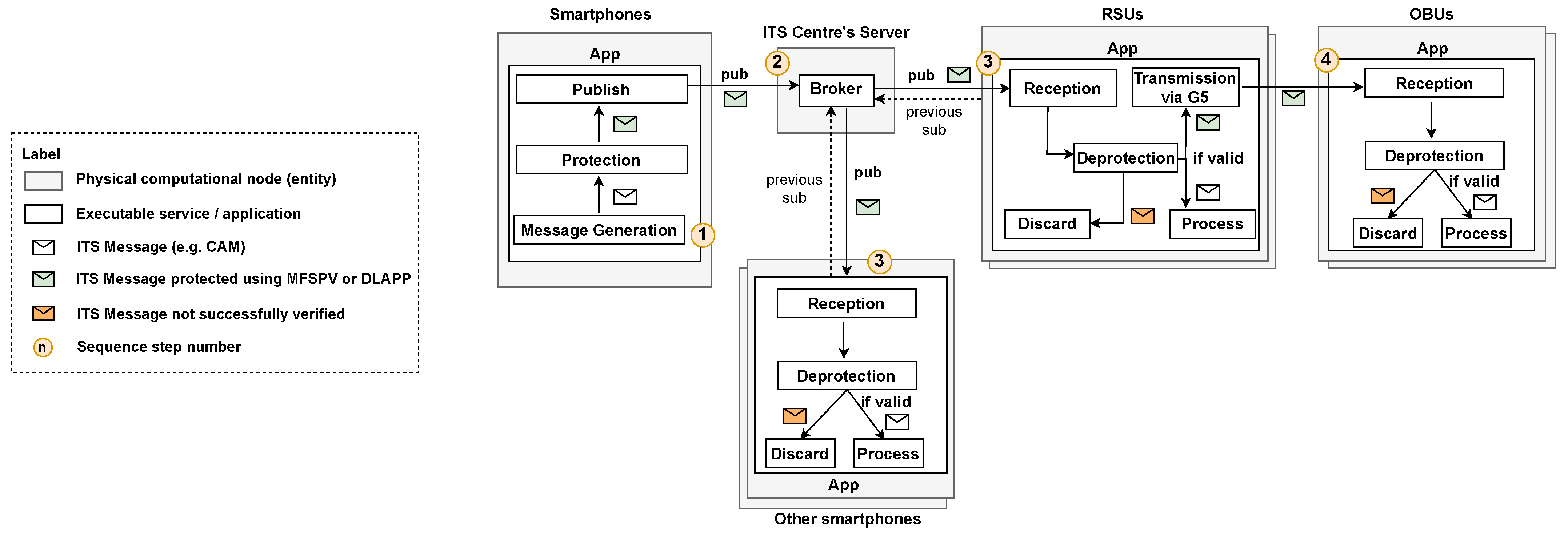
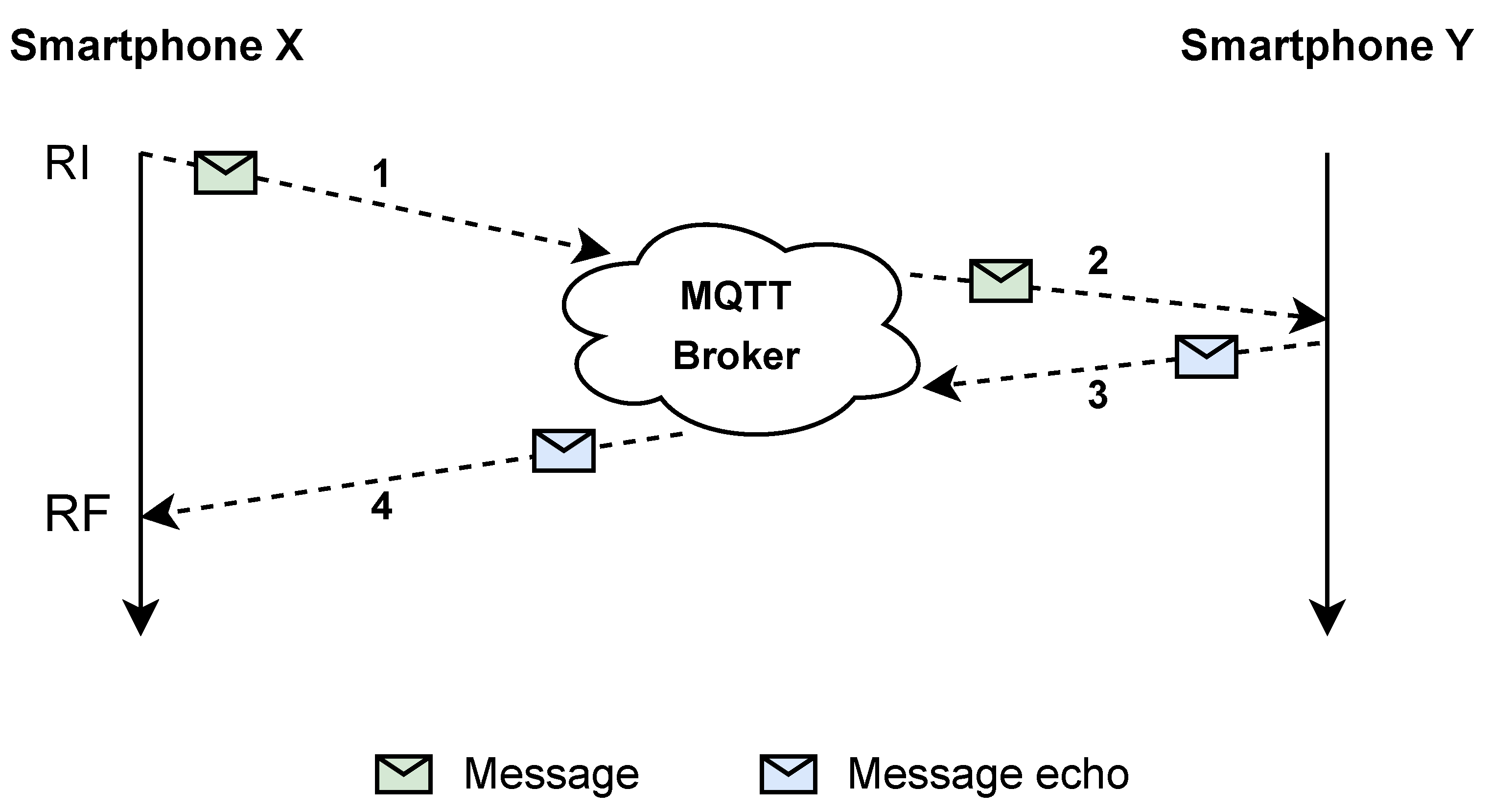
Figure 9 represents the inverse, i.e., the sequential flow when a smartphone generates a message. The step-by-step is as follows: (1) The smartphone that generates the ITS message protects with the configured protocol and publishes it. (2) The broker receives the message and sends it to all interested consumers. (3) When an RSU or another smartphone receives the message, it undergoes verification. If the validation is successful, the message is processed. RSUs also transmit it via G5 for reception by other ITS-Ss. In the case of validation failure, both RSUs and smartphones discard the message, which is not propagated to the G5 network. (4) OBUs receive the message via G5 and verify it.
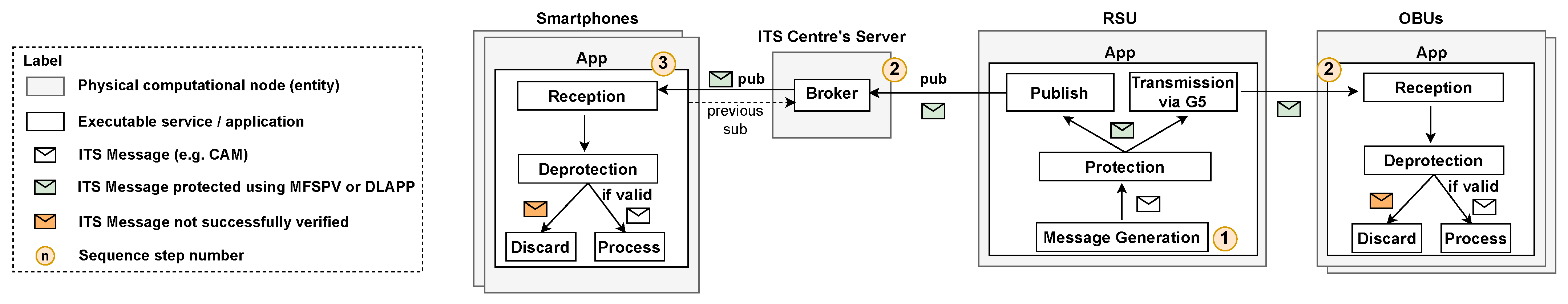
Finally, the sequential flow when the RSU generates a message is described in
Figure 10. The step-by-step is as follows: (1) The RSU generates the ITS message, protects it and sends it to G5 and cellular networks. (2) The broker and OBUs receive the message sent by the RSU. The broker sends it to all interested consumers. Conversely, the OBUs verify the message. If valid, they process it. (3) Each interested smartphone receives and verifies the message. If it is successfully verified, then it is processed.
Note that from the point of view of smartphones, their reception service is identical if the message is generated by the RSU or the OBUs. The same goes for the OBU; its reception logic is identical whether the messages were generated by the RSU or smartphones. This is no longer true for RSUs, as they act as an intermediary between the cellular and G5 networks. RSUs have a service to handle messages from each network. Moreover, it can be observed that there is no need to interact with the CA in any of the scenarios presented. This occurs because both protocols, MFSPV [
14] and DLAPP [
13], decentralise it so that there is no communication with the CA during the message exchange process.
3.2. Implementation
In this research, the CA service (
Figure 7) was not implemented, as in this phase, the priority was to exchange messages with security guarantees, and as seen (
Section 3.1.2), the CA is not utilised in that procedure. Consequently, when evaluating the protocols and system’s performance regarding secure message exchanges and hybrid networking, the absence of the CA does not impact the contemplated use cases or objectives. Nevertheless, it is to emphasise the importance of its implementation in future iterations of this work to test the complete system.
Regarding the broker technology, message queuing telemetry transport (MQTT) was used in this implementation. As stated in [
40], MQTT is lightweight and suitable for constrained environments. Thus, it is an approach for building event-driven solutions across edge and fog layers. In addition, its choice prevailed over other message-oriented middleware because when considering essential criteria such as latency, bandwidth/overhead and standardisation, MQTT stands out over other technologies, such as the advanced message queuing protocol (AMQP), Kafka and ZeroMQ [
41]. In particular, compared to Kafka [
42], MQTT is simpler in terms of implementation complexity [
41]. Due to the greater complexity of Kafka, e.g., the ability to store events (which is not relevant to this scenario, as the goal is to process messages timely), there are occasions that Kafka demands a more resource-intensive and slower process [
43]. These traits make Kafka less ideal than MQTT for our environment, where there is resource-constrained equipment in EC and FC.
Each node application implements and can be configured with one of three security approaches: No security, DLAPP [
13] or MFSPV [
14]. The software was modularised to be independent of the security approach in use. It expects an object representing the security protocol, with two methods: “protection” and “deprotection”. Protection involves applying a security protocol to a message and encapsulating it with the protocol. Deprotection entails verifying a message according to the configured protocol. If the message is valid, the security bytes are then removed. The “no security” approach was added so that it is possible to assess the security impact on the performance. As the CA was not implemented, each application has the cryptographic material configured locally. Empirically, for each node application (OBU, RSU and smartphone), the DLAPP protocol was implemented with a secret system key
of 32 bytes. Each element of the hash chain was obtained using the SHA-256 hash function. Therefore, each key is 256 bits long. In MFSPV, 32-byte keys were also used, such as the
and the
. Each entity’s application implementation will be briefly described, highlighting important considerations related to their development.
3.2.1. OBU
The OBU equipment (present in vehicles) used was the Unex EVK-301E. Two main difficulties were encountered during its application development.
The initial challenge arose from the difference between the execution and development environments. The execution environment was the equipment itself, which has an armv7-a architecture and a Linux Yocto operating system (OS). On the other hand, the development environment was an Ubuntu Linux 18.04 LTS 64-bit OS. Different compiling and running environments led to cross-compile and system library compatibility issues.
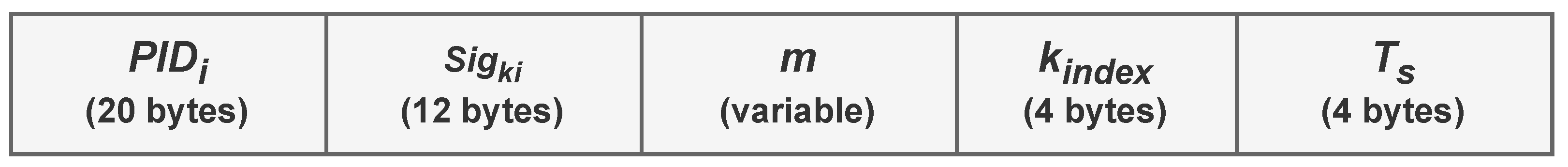
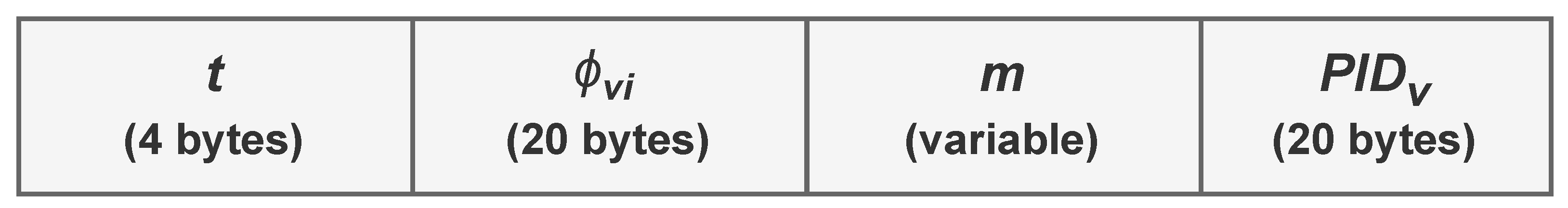
The other challenge was how to send messages in the format proposed by the protocols (
Figure 4 and
Figure 5). First, extending the messages (e.g., CAM) by adding additional fields was attempted. However, ITS messages are structured according to Abstract Syntax Notation One (ASN.1) definitions, leading to strict payload verification. Thus, only valid messages can be encoded (this also occurs in the RSU [
44]). Therefore, the chosen approach involves incorporating the protocol’s security bytes into the messages using optional fields. More precisely, the “PathHistory” field [
21], was utilised within CAM messages. While the “PathHistory” field is not being employed with its intended semantics, it allowed the development of the application using real equipment (according to the established objectives), avoiding the need for protocol stack and software modifications on the equipment.
Regarding the development of the OBU application, it was developed in the C programming language using the V2Xcast software development kit (SDK) available for the Unex OBU. As defined in the approach architecture (
Section 3.1), the OBU’s application has two main services. These are responsible for transmitting locally generated and receiving messages from the G5 network. These services are simplified in Algorithms 1 and 2. As can be seen, both involve a conversion process that is necessary due to the previous issue. OpenSSL and [
45] were used as cryptographic libraries.
| Algorithm 1 OBU app—Message transmission service (pseudo-algorithm) |
Require: security_protocol: Security protocol object
1: function transmit_message
2: cam_message_generation()
3: security_protocol.protection(encoded_its_message)
4: ▹(secured_its_message) is in protocol’s proposed message format
5: transform_format(encoded_its_message)
6: ▹ Insert security bytes into PathHistory
7: ⋯ transmit via G5 ⋯
8: end function
|
| Algorithm 2 OBU app—Message receiving service (pseudo-algorithm) |
Require: : Security protocol object
1: function receive_message(encoded_its_message) ▹ E.g. a received CAM
2: transform_to_protocol_format(encoded_its_message)
3: ▹ Convert to protocol’s proposed message format
4: security_protocol.deprotection(secure_message)
5: if then
6: ⋯ invalid message, discard it ⋯
7: else
8: ⋯ message successfully verified, continue processing it ⋯
9: end if
10: end function
|
3.2.2. RSU
The RSU equipment used in this work was the Siemens ESCoS RSU. RSUs are present in road infrastructure, connecting it to the G5 network.
In the equipment documentation [
46], the interface XFER is described. It is an RSU interface based on WebSocket Secure (WSS). It provides bi-directional data exchange and device management functions [
44]. It also enables the issuance of commands to the RSU so that it has certain behaviours; for instance, echoing a received message. Therefore, this interface was chosen to help implement the RSU application. However, this approach requires the presence of a client. An intermediary component, Middleware RSU (M_RSU), was developed to address this, acting as an XFER client. For this reason, the Siemens RSU will be referred to as Physical RSU (P_RSU). The combination of these two components is referred to as the RSU, as both combined have the expected behaviour of an RSU in the proposed approach. The M_RSU application was developed in Python and used the standard library modules for cryptographic operations.
As seen before, the RSU handles three different message exchange scenarios. Thus, M_RSU and P_RSU act together to perform them. Each one of them is described below:
Cellular Network (Smartphone) → RSU First, the M_RSU receives the secure message via the broker. Then, it validates the message (deprotection), and if it is valid, sends it to the P_RSU’s XFER interface, which will forward the message to the G5 network. Before sending it to the P_RSU, the M_RSU first converts the message from the protocol format to the format that the OBU requires.
G5 Network (OBU) → RSU As an XFER client, the M_RSU uses the “subscribe” command to instruct the P_RSU to forward upstream and downstream messages. Therefore, when the P_RSU receives a message from the OBU, it forwards it to the M_RSU, where it undergoes validation (deprotection). If the message passes validation, it is published for smartphones to receive.
RSU → G5 and Cellular network In this scenario, the messages are being generated by the RSU. M_RSU will protect them and send them to the cellular network (via the broker) and the G5 network (via the P_RSU).
3.2.3. Smartphone
Lastly, the smartphone application was implemented as an Android app using the Java Cryptography Architecture (JCA) as the cryptographic library. Mirroring the dual functionality in the OBU application, it primarily focuses on two services: transmitting locally generated messages and receiving messages from the broker.
4. Experimental Evaluation and Results Analysis
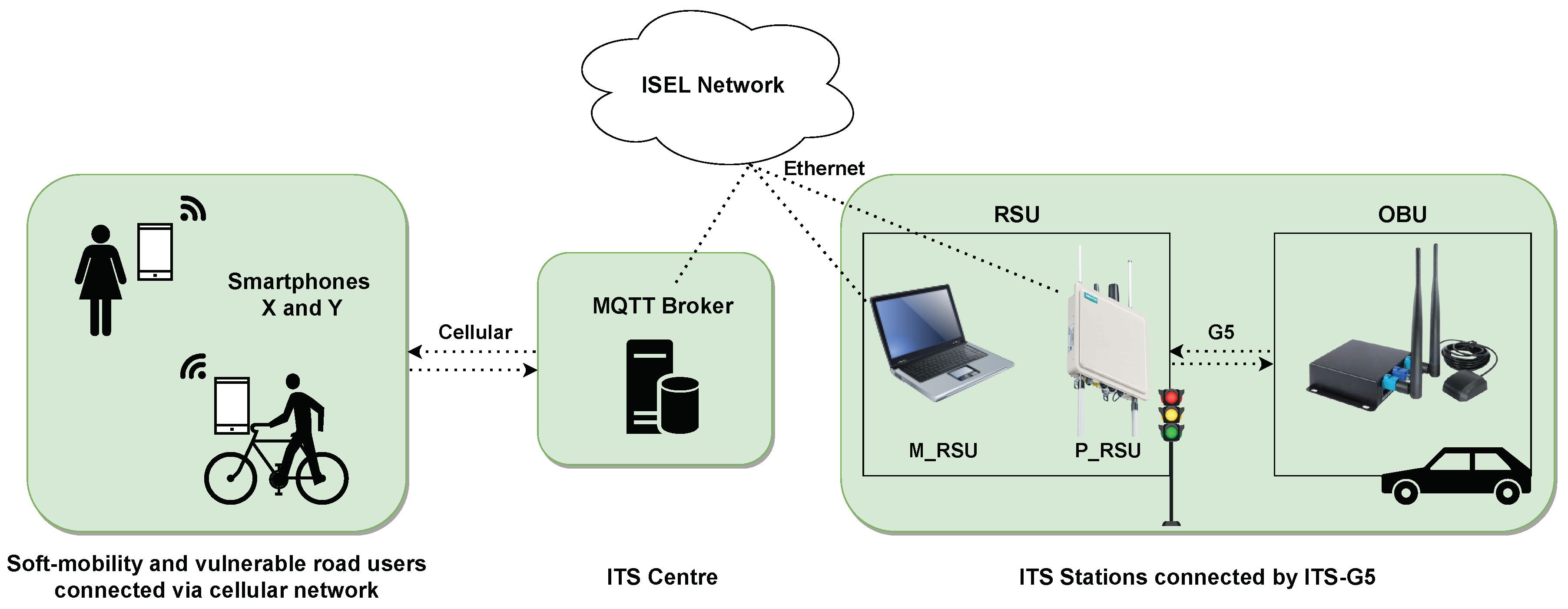
This section outlines the experimental evaluation process and analyses the obtained results. All latency results depend on the used equipment, namely the node computational capacity. Therefore, nodes with high computational capacity will decrease the latency overheads presented. The testing environment is depicted in
Figure 11.
On the left is a representation of the cellular network (e.g., 5G) serving soft-mobility users with two smartphones (X and Y). In the middle, the ITS centre is hosting the MQTT broker connected to the ISEL network. This is the university’s network where all the tests were conducted, thus bringing the evaluation closer to a real-world scenario. On the right, and also connected to ISEL’s network, are the laptop (M_RSU) and the Siemens P_RSU. This one communicates with the OBU, both representing the ITS stations (e.g., a traffic light and a car) connected by ITS-G5.
In this experimental setup, the environment is structured in the context of the EC and FC models [
15,
47]. Smartphones X and Y, along with the Unex OBU and the RSU, operate at the edge of the hybrid network and process data within their respective local application. In addition, the ITS centre acts as an intermediary in the fog layer due to its proximity to the edge [
17,
48].
Table 6 describes each equipment computational environment.
The developed work is assessed in different aspects. Firstly, in
Section 4.1, the local computation time of each execution environment application (RSU, OBU and smartphone) is measured. Next, in
Section 4.2, communication latency is measured for three security approaches. Finally, in
Section 4.3, the end-to-end times of each workflow are calculated.
4.1. Computation Time
This section performs a local computation performance comparison and analysis in each node using three security approaches—No security, DLAPP [
13] and MFSPV [
14]. This allows to draw insights into how each security approach performs with real hardware in different execution environments and a slightly different context of mobility (with smartphones). To achieve this, the evaluation procedure consists of two modes.
Total Computation Time Measures all the local computation times (CTs) from the beginning of a transmission or reception processing until completion. This evaluation may be used with any security approach.
Security Computation Time Measures the CTs for security protocol protection and deprotection. This mode must be used with a security protocol (DLAPP or MFSPV). Protection involves applying a security protocol to a message and encapsulating it with the protocol bytes. Deprotection entails verifying a message according to the configured protocol. If the message is valid, the security bytes are then removed.
In summary, the evaluation objective is to measure the total and security CTs in each computing node without considering the network latency, only the local computing.
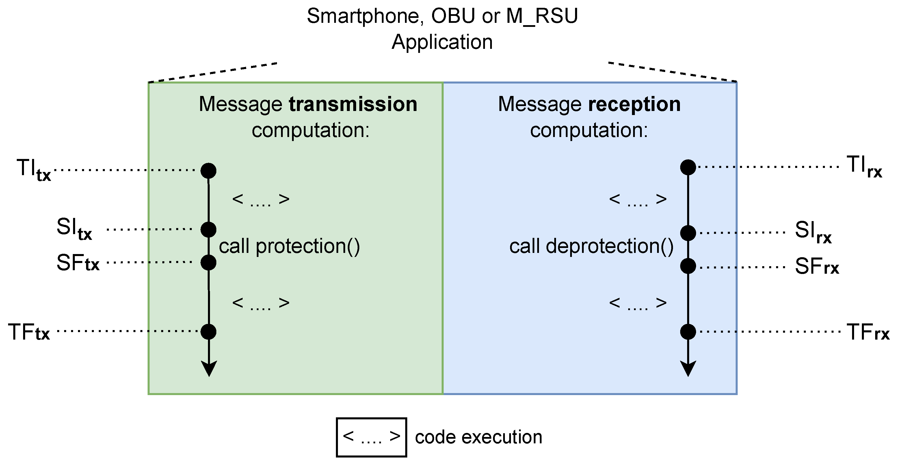
The extraction of the necessary timestamps in each mode is illustrated in
Figure 12. These are used in the computation time calculation, as given by Equations (
6) and (
7).
where:
t—total CT measurement;
—total CT initial timestamp;
—total CT final timestamp;
s—security CT measurement;
—security CT initial timestamp;
—security CT final timestamp.
Figure 12.
Total and security computation times extraction representation for transmission (tx) and reception (rx).
Figure 12.
Total and security computation times extraction representation for transmission (tx) and reception (rx).
Note that the processing results obtained by the RSU will be given less emphasis as it does not fully represent the actual RSU execution environment. Therefore, regarding the computation performance evaluation, the OBU and smartphone results are more relevant. From the set of all combinations—computing node, evaluation mode, and security approach—about 2000 samples were extracted to make the obtained values more accurate.
4.1.1. Performance Analysis: DLAPP
According to the DLAPP’s proposal [
13], its signature and verification simulation took 0.0167 ms (each operation). However, the study only measured the time of the HMAC cryptographic operation, thus being a theoretical estimation. It is essential to include all the computation associated with protecting and deprotecting a message to have a realistic measure of the computation time. The experimental performance results of the DLAPP protocol are shown in
Table 7 (from a total of ∼500 messages, one per second).
It can be concluded that, when using hardware (OBU and smartphones), the actual performance falls short (∼90 to 95%) of what was initially projected in the protocol proposal. This can be attributed to the initial projections being based on simulations and not considering the entire protection and deprotection process.
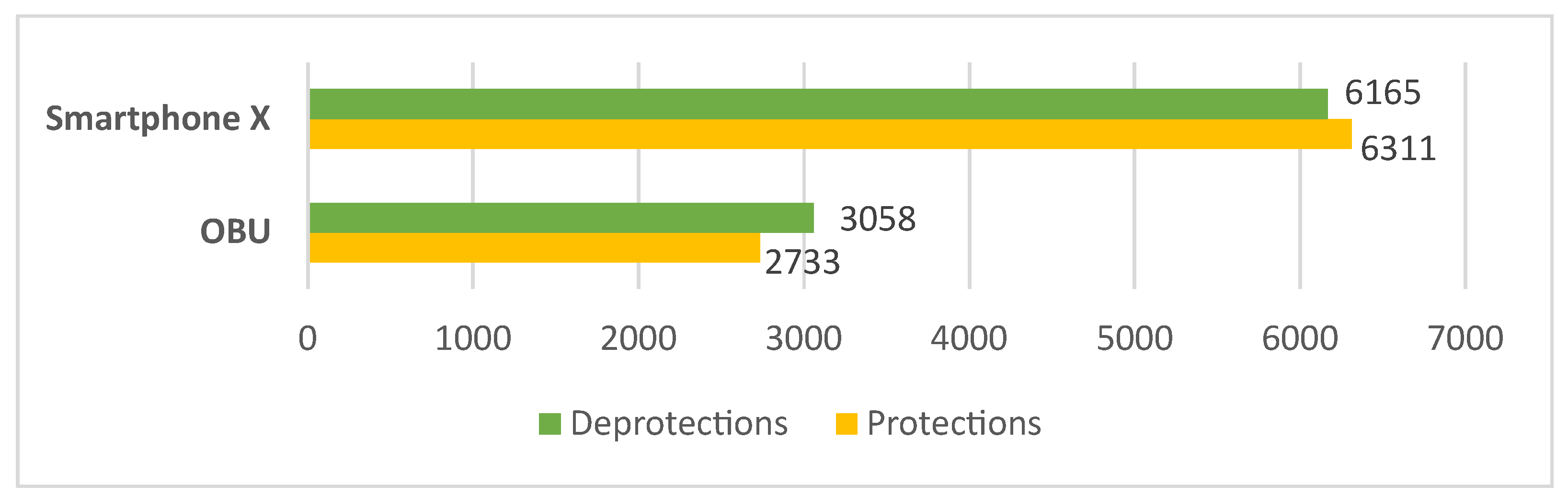
Calculating the total operations per second as the DLAPP’s proposal [
13] does, the smartphone can protect up to 6311 and deprotect 6165 messages per second (
Figure 13). Conversely, the OBU has a lower capacity, protecting 2733 and deprotecting 3058 messages per second. This performance difference (∼54%) may be attributed to the inherent limitations of OBUs as a resource-constrained device [
14], as can be seen by its specifications in
Table 6. Furthermore, the relation between protection and deprotection times exhibits similarity across all nodes. This is because the primary time-consuming factor is the HMAC, which is common in both operations.
Assuming a similar high-vehicle-density scenario as [
13], i.e., 180 vehicles within communication range, sending a packet every 100 ms, this would result in 1800 messages needing to be verified per second. Based on the results (
Figure 13), the DLAPP protocol is computationally light enough to manage such a type of high-node-density scenario.
4.1.2. Performance Analysis: MFSPV
Similar to the DLAPP proposal [
13], MFSPV’s authors [
14] only considered the SHA-256 cryptographic operation to calculate the generation and verification times. They claim that MFSPV’s protection takes 0.018 ms and that deprotection takes 0.006 ms. The MFSPV’s performance results of this study are shown in
Table 8 (from a total of ∼500 messages).
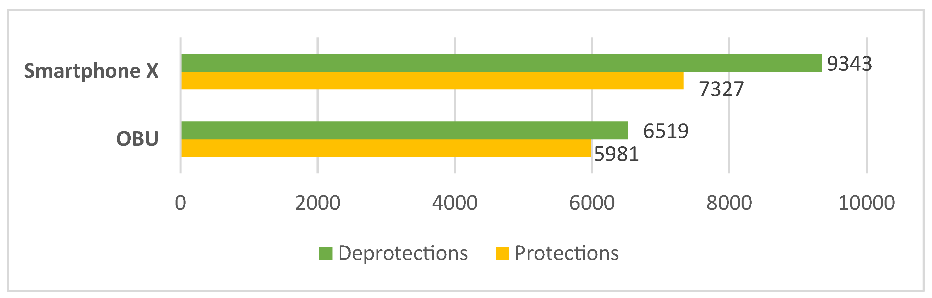
By analysing the results, and as concluded in the DLAPP’s performance analysis, the estimations provided in the proposal protocol [
14] are higher than the ones obtained (for the same reasons). Moreover, smartphone X can protect up to 9343 and deprotect 7327 messages per second (
Figure 14). The OBU, as before, presents a lower performance than the smartphone, protecting 5981 and deprotecting 6519 messages per second. Unlike the DLAPP protocol, the protection and deprotection operations in MFSPV are not so similar. Deprotection exhibits lower computation times (∼8% to 53%) on all nodes. This occurs because the protocol performs more hash operations in protection than in deprotection.
Assuming the previous high-vehicle-density scenario, i.e., 1800 messages needing to be verified per second, the MFSPV was also computationally light enough to manage this high-node-density scenario on OBUs and smartphones.
4.1.3. Performance Analysis Comparison
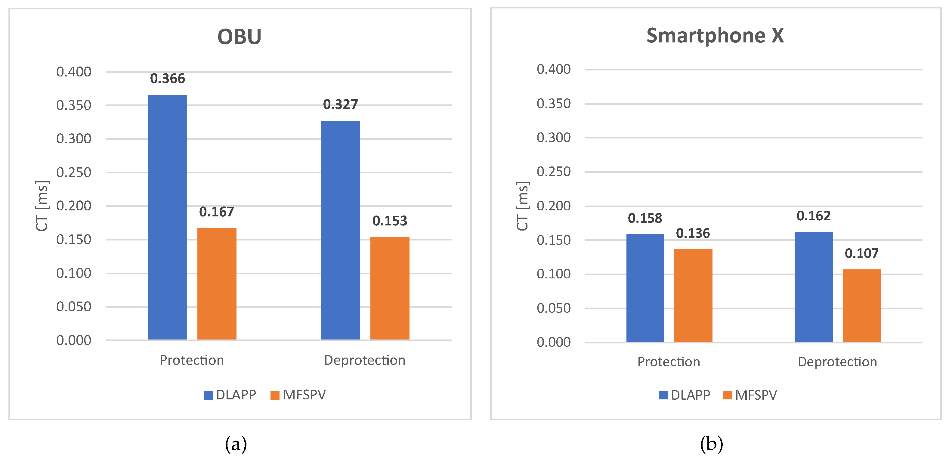
Figure 15 reports the median security CT results for DLAPP and MFSPV in OBU and smartphone X. MFSPV outperforms DLAPP in both nodes. Analysing this difference from the perspective of operations per second, MFSPV allows the protection of 3248 and 1016 more messages on the OBU and smartphone, respectively; plus 3461 and 3178 message deprotections. This translates into a performance increase between ∼16% to 113%, depending on the node and type of operation. MFSPV achieves this performance advantage due to the exclusive use of hashes, which are computationally lighter than the HMAC operation. Despite this, as both protocols were designed to be lightweight, the magnitude of the times involved is minimal—in the order of tenths of milliseconds.
4.1.4. Security Impact on Performance
This assessment measures transmission and reception computation times across all three security approaches. As a result, it provides insights into the impact of MFSPV and DLAPP on the application’s performance.
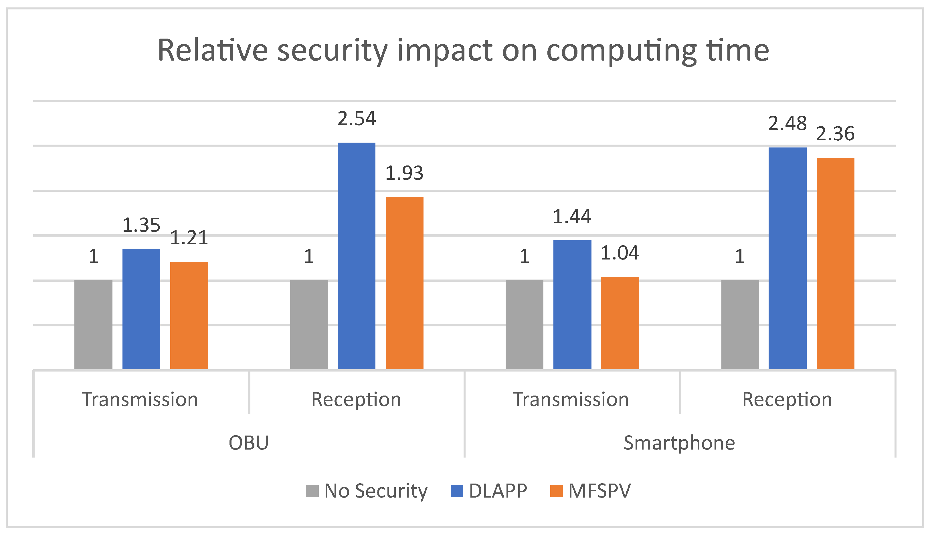
Figure 16 presents the total CT results but expresses each time as a relative ratio of the reference task (baseline), which is the non-use of security, making it easier to assess the security impact in performances.
In transmissions, DLAPP increases the computational time by 35% on the OBU and 44% on the smartphone. In comparison, MFSPV increases it by 21% on the OBU and 4% on the smartphone. DLAPP has a more significant impact on the computing time than MFSPV, as expected according to previous analyses. The same applies to reception times, but greater relative increases can be seen in this case. This difference is understandable since reception times are lower than transmission times (the order of magnitude is smaller). Consequently, even minor increases in reception times result in more pronounced relative changes. Nevertheless, the impact of protocols on reception is still low, increasing it in tenths of a millisecond.
4.2. Network Latency
Latency is an important performance indicator in communication. For this reason, this section assesses the latency of the developed hybrid network. To perform these tests, the round-trip time (RTT) was utilised.
Figure 17 describes the adopted methodology.
This methodology was used to calculate the communications latencies involving the cellular network segment. The timestamps (
and
) are used to calculate the transmission latency, as given by Equation (
8).
where:
The above methodology was used in the calculation of latency of the following communication flows: (i) X → Smartphone Y, (ii) Smartphone X → RSU, (iii) M_RSU → Smartphone X. A slightly different strategy was adopted to calculate the communication latency in G5 (between the P_RSU and OBU).
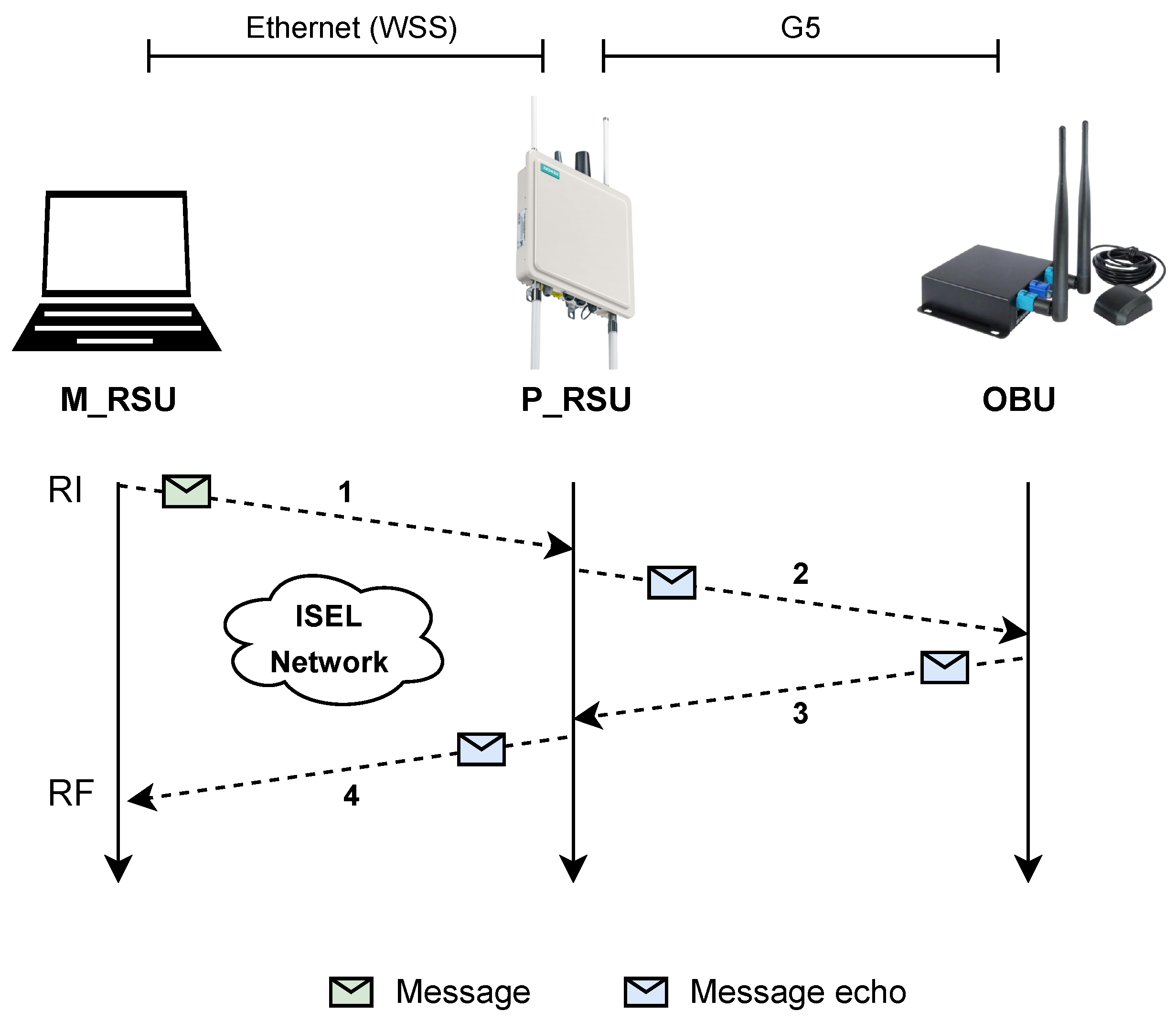
Figure 18 illustrates the methodology used, while Equation (
9) shows the latency calculation.
where:
— latency measurement of G5 network segment;
— initial timestamp;
— final timestamp;
— latency measurement of WSS communication (between the M_RSU and the P_RSU).
Figure 18.
Methodology for calculating latency in G5 communications.
Figure 18.
Methodology for calculating latency in G5 communications.
The M_RSU was used to help extract G5 latency measurements. By eliminating the latency linked to WSS communication, the G5 transmission latency is calculated. In all conducted tests, ∼2000 latency samples were extracted, with a message transmitted once per second. Due to the occurrence of outliers, as illustrated in
Figure 19, the median values are reported.
4.2.1. Latency Measurements Analysis: Cellular Network
The latency values involving the cellular network are shown in
Table 9.
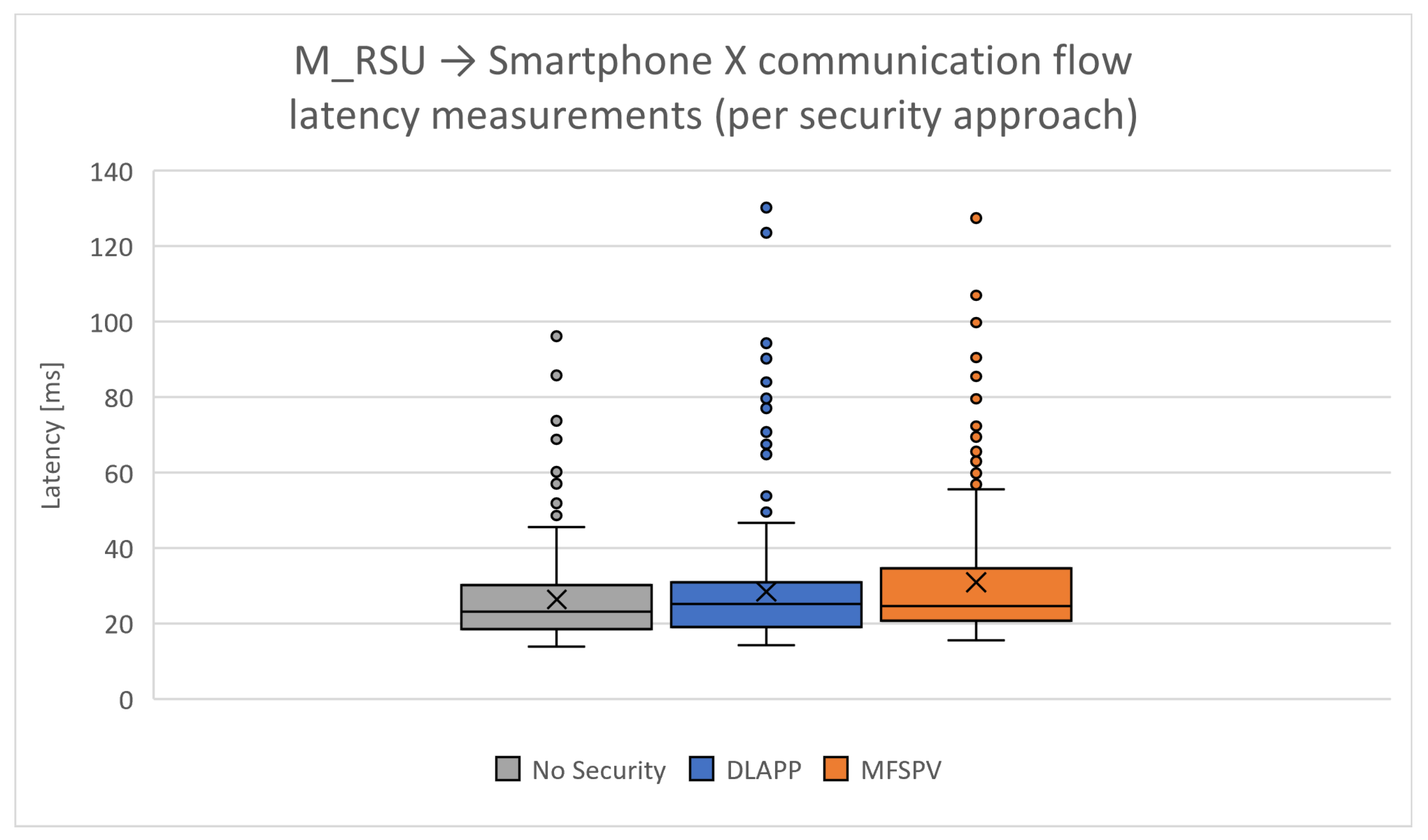
The M_RSU → Smartphone X flow shows better results than the flows in which smartphones are the source. This may happen because, as shown in the testing environment (
Figure 11), the M_RSU is in a privileged position as it is connected via Ethernet to the ISEL network, as is the MQTT broker. It is also observed that there are higher latencies in communications between smartphones, which is justified by the fact that both are on the cellular network, which contributes to higher latencies.
Upon individual analysis of each communication flow, the omission of a security protocol results in the most favourable latency measurements, which is expected due to message payload overhead. Among the results of each protocol, DLAPP, with four less bytes of overhead than MFSPV, exhibits slightly better performance on two occasions when compared to MFSPV. These results indicate that the difference of 4 bytes does not significantly influence the use of one protocol over the other. On average, when compared to scenarios where no security is used, DLAPP increases the cellular network latency by 6.8%, while MFSPV increases it by 7.5%.
4.2.2. Latency Measurements Analysis: G5 Network
The latency measurements of G5 communications (RSU and OBU) are reported in
Table 10. DLAPP increases the latency by 6% and the MFSPV by 10%. The impact of the protocols on the G5 network is not very noticeable.
4.2.3. Latency Measurements Analysis Comparison
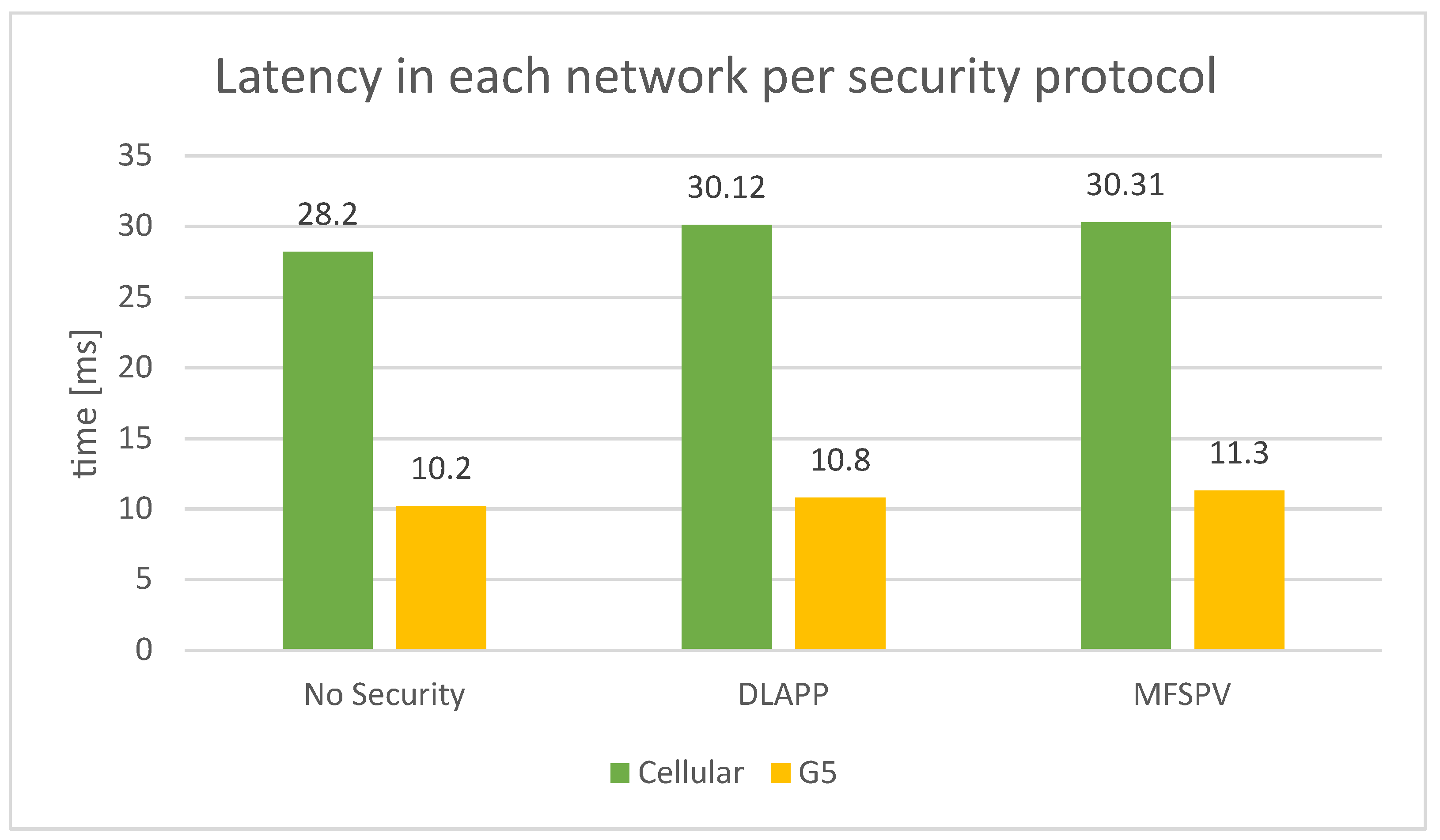
The comparison of the latency measurements of the cellular network and the G5 is illustrated in
Figure 20. The G5 network, on average, has 63.6% lower latency than the cellular network. It achieves a shorter transmission time across all security approaches. This difference is justified by the transmission in G5 being direct (ad hoc), without needing a broker, thus being more efficient. The impact of the security protocols on network latency is, on average, 7.1% on the cellular network and 8% on the G5 network. Comparing both protocols, DLAPP is slightly more efficient. However, this difference is minimal as it represents tenths of milliseconds, which is justified by the fact that there is only a 4-byte difference in the payload.
4.3. End-to-End Assessment
End-to-end (E2E) is an important indicator when developing a system, as it is crucial to know how long the system takes to perform a job, from the start of a workflow to the end. Therefore, the E2E time will be calculated for each communication flow of the developed prototype. All the measurements collected in the computation time and latency sections will be used to obtain approximations of the E2E, i.e., it will be calculated according to the existing processing time and latency in each communication flow. It uses the median values obtained in the computing and networking latency experiments. In total, approximately 4000 measurements were collected across all the conducted assessments. The calculated E2E times for each combination between nodes are reported in
Table 11.
The results are analysed from two perspectives: the network segment and security approach. Following this analysis, the applicability of the developed proof-of-concept is briefly discussed based on the results obtained.
4.3.1. Analysis per Network Segment
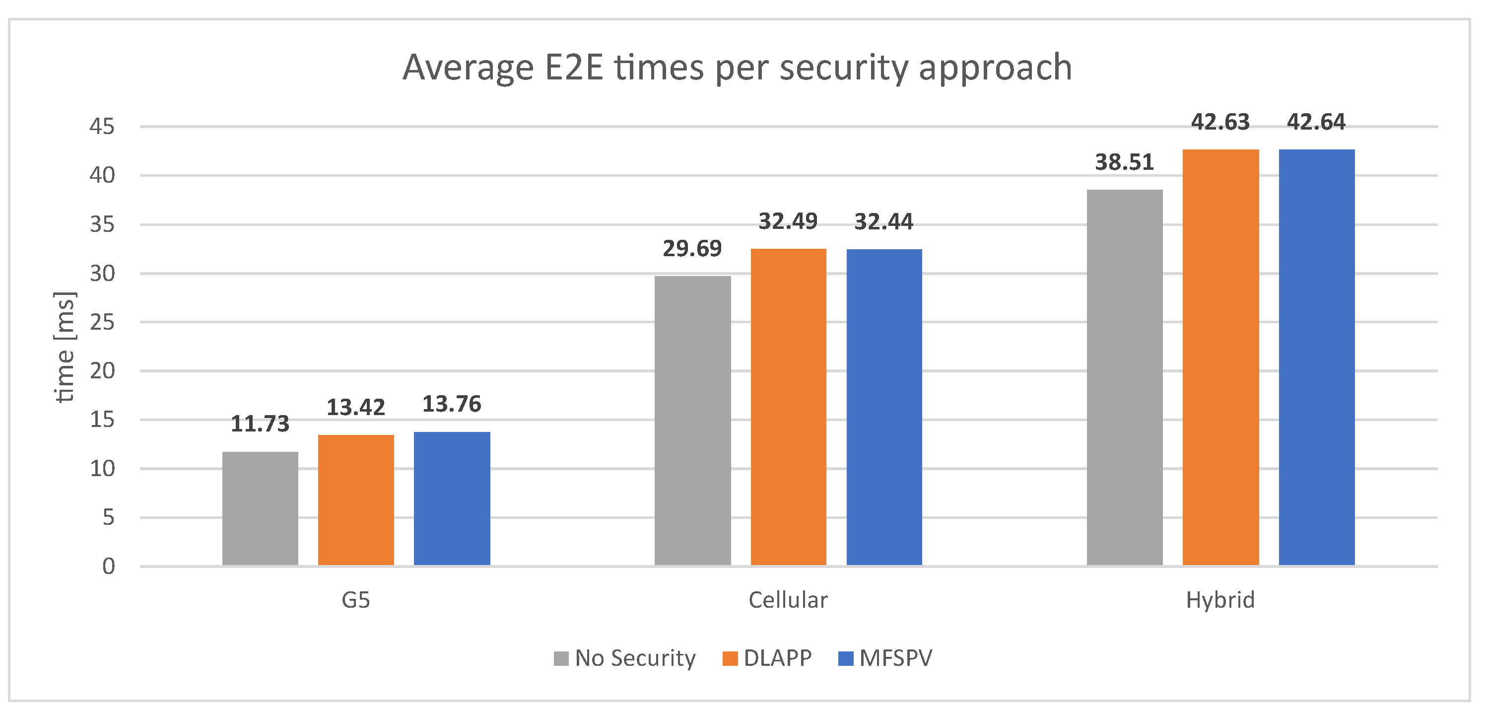
The most time-consuming E2E communication flows are seen in the hybrid network communication flows, where messages are generated in the OBU and propagated until the smartphone and vice versa. In particular, the greatest median E2E time is observed in the flow Smartphone → OBU using the MFSPV protocol, 46.75 ms, which was anticipated. The hybrid network’s communications flow shows an average E2E time of 41.26 ms.
Conversely, the E2E times achieved by G5 exclusive communication flows are the lowest, namely in the OBU → RSU flow, where the E2E time is just 11.63 ms without the use of security. The G5 network shows an average E2E time of 12.97 ms.
From these E2E results (
Table 11), it can be concluded that hybrid communication flows impose (on average) an extra 28.29 ms of E2E time, which translates into an increase of 218% compared to G5-only communication flows.
Table 12 illustrates the average E2E results obtained in each network segment.
4.3.2. Analysis per Security Approach
Figure 21 summarises the E2E results, focusing on the analysis of the protocol impact.
As observed in the experiments conducted so far, the security protocols have a low impact on performance compared, for instance, to the extension to hybrid networks. In the E2E results, the same happens. For example, the additional E2E delay imposed by the protocols in the hybrid segment workflows is approximately 11% in both protocols. MFSPV proves to be more efficient in local processing, and DLAPP attains slightly shorter latency values. Nonetheless, looking at the big picture (
Figure 21), both impose a similar additional E2E time.
4.3.3. Applicability Considerations
On a final note, as referred in [
49,
50], various use cases have defined specific requirements for maximum latencies. The most stringent among them are emergency services, such as pre-crash warnings, which require a 50 ms maximum latency. In comparison, most other use cases require a maximum latency of 100 ms. With this understanding and examining the obtained results, significant conclusions can be drawn.
The median E2E values, as shown in
Table 11, do not surpass ∼47 ms. This indicates that the developed approach aligns well with the requirements of many use cases. However, focusing solely on median values does not provide a complete picture. Therefore, the highest E2E time was also calculated, representing the worst-case scenario regarding latency and computational measurements.
The highest E2E time was encountered in the communication flow smartphone X → OBU using the DLAPP protocol, reaching an E2E time of approximately 190 ms. Nonetheless, it is important to note that these values are considered outliers. Outliers were identified using the interquartile range (IQR) method, specifically, values above
or below
, as illustrated in the box plot in
Figure 19.
Lastly, the same analysis was repeated, i.e., considering maximum values but now excluding outliers. In this case, the maximum E2E time observed was 86 ms in the smartphone X → OBU communication flow using the MFSPV. This means that, when assuming the worst-case scenario while excluding outliers, the results obtained in this study still remain at 14% below the maximum latency requirements for many use cases [
50], such as automated shuttle remote driving [
49].
5. Conclusions
C-ITS/V2X communication is open and vulnerable to attacks, posing privacy and safety risks to road users. Moreover, a high fatality rate is correlated with more vulnerable modes of transportation. Therefore, developing C-ITS solutions requires considering all road users’ needs, not only vehicles. This study proposed a security approach within a C-ITS ecosystem while accommodating soft-mobility users and legacy vehicles. Security protocols were used in a C-ITS setting that enabled integration between connected ITS stations using ITS-G5 and soft-mobility users through smartphones over cellular technologies (hybrid networks). Two security protocols (MFSPV and DLAPP) were implemented using real hardware equipment (OBUs, RSUs and smartphones), and for each computing environment, an application was developed. Experiments were performed to evaluate the developed ecosystem. More specifically, computational, transmission and end-to-end latency were assessed.
For the used experimental setup, MFSPV proved to be 16% to 113% more efficient than DLAPP, depending on the computational node and operation (protection or verification). Despite this, as both protocols were designed to be lightweight, the magnitude of the times involved is minimal, in the order of tenths of milliseconds. Moreover, both presented a low impact on local computing time compared to situations where security was not used. As for network latency, experimental measurements have shown that DLAPP is slightly more efficient as it increases G5 and cellular network latency by 6.4%, whereas MFSPV provides an 8.8% increase. Furthermore, the G5 network, on average, has 63.6% lower latency times when compared to the cellular network. Regarding the end-to-end assessment, the most time-consuming E2E communication flows were seen in the hybrid network communication flows, which is expected since messages travel via both G5 and cellular networks. In particular, the highest E2E time was 46.75 ms. Conversely, the E2E times achieved by G5-exclusive communication flows were the lowest. On average, the extension for hybrid communication imposes an extra 28.29 ms of E2E time. Concerning security, the additional E2E time imposed by using security in hybrid communications was ∼11% in both protocols.
In general, the DLAPP and MFSPV protocols imposed similar additional E2E times. Therefore, choosing one over the other in terms of efficiency is not straightforward. The choice should depend on the specific priorities of the application. As a final remark, the suitability of the presented approach depends on the specific nature of the ITS applications it will incorporate. That is, different ITS use cases have distinct maximum latency demands. The most stringent ones, such as emergency services, require a 50 ms latency, and most others allow up to 100 ms [
49,
50]. This study’s median E2E values do not surpass ∼47 ms, aligning well with the requirements of most use cases. In a worst-case analysis, the E2E time reached around 190 ms. However, it represents an unusual scenario. Therefore, outliers were isolated using the IQR method. In this scenario, the worst-case E2E latency remained at 86 ms, 14% below the maximum latency of 100 ms. Thus, one may conclude that the obtained results align well with the requirements for many use cases. Finally, the architecture proposed for implementation in the Siemens RSU and Unex OBU presents versatile applicability to other commercial equipment. This implementation recommendation serves as a practical approach as it avoids the need for protocol stack and software modifications across diverse equipment from various manufacturers.
For future work, the CA should be developed to allow evaluation of the whole prototype. A security analysis should be performed, including a risk assessment of our implementation using appropriate tools. In addition, experiments should be carried out with more OBUs and RSUs from different manufacturers. This would allow a comparison of the results and thus strengthen the applicability of the solutions. Finally, it is also desirable to carry out evaluations under more stress/overload conditions, including both computational and network aspects, in order to analyse the response of the system to extreme real-world scenarios.


