1. Introduction
The well-known and modern paradigm of the Internet of Things (IoT) represents the way in which devices are interconnected in order to sense and collect data and give relevant real-world reports. IoT systems may connect anyone and anything at a certain time and place to provide the services that make human life easier. The billions of IoT sensors generate large data volumes for use, analysis, and interpretation. The term “IoT” was originally used for interpretable objects that are connected and identifiable with radio-frequency identification (RFID) technology in a unique way. Sensors, actuators, and Global Positioning System (GPS) devices are all considered IoT devices.
IoT systems can evolve human lives through the ability to extract and analyze large volumes of data and apply them to automated processes and applications. These potentials are manifested in the main building blocks of sensing, communication, computation, and services. IoT systems deal with data in two ways: with command processing and with the storage and processing of data. Microcontrollers and microprocessors represent the processing units and enable the computations in IoT operating systems. The processing units are also referred to as the “brain” of IoT systems. The places used to store the massive amounts of data that are processed in the processing units are called cloud units. Smart devices transmit data to the cloud and extract useful knowledge from this huge data collection. Nowadays, IoT services can be hosted by free or commercial cloud platforms [
1]. The quality of device communication among devices, the data collection methods, and the data processing represent the influence of IoT technology on the Internet. While in the traditional object-oriented view, everything is an object, in the IoT paradigm, everything is a smart object, meaning that objects can communicate over the Internet or via radio communication technologies [
2].
IoT smart objects may have one or more embedded sensors to sense or, in other words, capture massive amounts of data. The data types can be divided into 3 groups: status data (the raw and basic data on the state of an end device), automation data (created by automated systems such as smart thermostats), and geographical location data (frequently used in manufacturing and logistics). The data sensing services are located on top of the IoT infrastructure. These smart sensors can be bought or rented through middle-ware service providers who interconnect sensors to back-end software systems. The selection between the existing IoT solutions and the successful deployment of sensors are challenging tasks. The best choices for IoT networks are wireless sensors, but as all are powered using batteries, they are constrained in terms of their energy. Hence, another challenge is power maintenance for tasks such as data sampling and radio communication processes. Specifically, when the sensors are installed in remote and distant areas, inside buildings, or underground, the concern of maintaining sensor power for longer periods gains importance. One way to prolong the network lifetime is to conserve the energy by reducing the costs for data sampling and processing, as well as by finding feasible ways to harvest energy from the environment. The type of radio communication technology used for sensor communication can also have a huge impact on the power consumption of IoT devices.
The development of industrial and business models is lagging behind the technological innovations, so the very recent advancements in information technology or IT have accelerated the growth of inventive business models. IoT technology enables hybrid business models with digital and physical systems, some of which are widely used, such as in e-commerce, crowdsourcing, and crowdfunding. These new business models deeply rely on the enhancement and optimization of the user experiences to support customer responsiveness [
1].
The fast-evolving concept of the Internet of Things represents a definitive future direction and strategic path to adopting the most advanced information communication technology infrastructures with futuristic architectures. IoT systems in this sense do not just comprise millions of computing machines and software programs, but additionally billions of devices such as sensors, actuators, and robots and trillions of digitized and sensitive small objects. Academics, industry, and business professionals are constantly seeking business and technical use cases for IoT to prove the transformational power of IoT to larger audiences [
3].
This paper gives a detailed view of the main radio communication technologies that are used today in IoT applications. Studying the core aspects and the features of these technologies, as well as the market trends, it is possible to give a general comparative conclusion on which of the studied technologies fit the best for most IoT use cases. Usually, the candidates enabling the sensor node communication are mobile communications technologies such as the Global System for Mobile Communications (GSM), the General Packet Radio System (GPRS), Universal Mobile Telecommunication System (UMTS/3G), Long-Term Evolution (LTE/4G), satellite communications, licensed or unlicensed radio networks, and power line communications (PLC). When transmitting or receiving data, the sensor nodes establish radio links, making them IoT nodes [
1]. For now, NB-IoT radio communication technology as an extension of LTE seems to be the leading technology in this field, so one chapter is dedicated to giving a detailed explanation of NB-IoT and its architecture. After this, IoT platform models and architectural designs used today are discussed. Generally, the architecture of an IoT system is layered, comprising the application, common service, and network service layers. The application layer is where the business and operational logic is implemented, while the common services and network services include machine-to-machine connection (M2M) functionalities (such as management, discovery, and policy enforcement) and the connectivity for data transfer. The design of an IoT application can be simplified into 3 layers horizontally starting from the IoT platform, to the connectivity layer, and down to the sensor layer. To deeply understand how the sensors communicate with the IoT platform, a chapter is dedicated to explaining communication protocols used to enable sensor–node communication through the IoT infrastructure.
Various IoT networks are created with numerous sensors and actuators, including homogeneous and heterogeneous ones. Some to mention include the sensors used for machine vision or optical ambient light applications; the sensors used for acceleration, motion, position, presence, humidity, temperature, moisture, leak, and level sensing; as well as the electric and magnetic sensors [
1]. After providing a detailed view of the above concepts, in the context of a smart city, a smart parking solution using NB-IoT radio communication technology is given to showcase a concrete implementation example of IoT concepts. In a smart city, the infrastructure comprises various data collection sources (sensors, microcontrollers, and system provider networks). The upper layers include data orchestration, service enablement, and application layers. The IoT platform aims to manage the devices and the applications and services are in the application layer or on top of the core platform [
4].
2. Radio Communication Technologies
Various communication technologies have been developed depending on the deployment characteristics and requirements of the IoT use cases. While establishing efficient radio technologies for IoT connectivity, it is important to highlight the end-to-end use case factor in IoT-based networks, as every two nodes need to be connected. IoT connections are generally classified into three categories based on the use cases. The current networks used include 2G, 3G, LTE, and WiFi, which cover the first and second classes, while the third classes requires smarter approaches to IoT connections. A “smarter” approach includes catering for low device power consumption, supporting a huge number of connections, and decreasing the costs for the end units or modems.
Short- and medium-range wireless protocols such as Bluetooth, WiFi, and ZigBee are range- and power-restricted, so they are not an ideal fit for IoT applications. Additionally, traditional long-range wireless protocols usually have strict power requirements that are not suitable for battery-powered devices [
5]. The need for low-power and wide-area networks (LPWANs) to connect massive numbers of sensors with battery lives ranging from 5 to 10 years and modules, enabling low-cost, long-range coverage, has led to the third class of connectivity (
Figure 1). The third class or LPWAN has evolved the IoT development process and is available as licensed and unlicensed bands.
LPWAN is rapidly becoming the leader in the field. Strategic analyses and predictions indicate that network operators could make over
$13 billion from LPWAN connectivity and from the additional service profits related to data analytics and security support. The numbers say the most, and the connectivity revenue of LPWAN technologies increased to
$7.5 billion in 2022 [
4].
LPWAN technologies have evolved with the characteristics below [
6]:
Very low power consumption—Having 50 million IoT-connected devices that consume a huge amount of energy will lead to environmental catastrophes and is not economic. For this reason, over 10 years of optimized battery life for smart parking, smart environment, and smart home devices is a must for LPWAN connections;
Brief messaging—LPWAN systems have optimized solutions for messaging within the length of an SMS;
Decreased device costs—The economic approach enables the connection of each module at the cost of a few dollars;
Outdoors and indoors coverage—As IoT nodes are mainly integrated sensors, it is necessary to support their connectivity in rural locations, underground, in walls, and in building basements;
Easy network installation—In some cases, the use of LPWAN has made the reuse of existing cellular components possible;
Scalability—Connecting large numbers of devices over wide geographic areas is another smart characteristic of IoT communication technologies.
As can be seen in
Figure 2, LPWAN technologies are divided into two subgroups:
The 3rd Generation Partnership Project (3GPP)-licensed technologies, including NB-IoT (narrowband IoT) standardized by the 3GPP standards body, LTE-MTC (LTE-machine-type Communication), and EC-GSM-IoT (extended-coverage GSM-IoT), with capabilities to support existing cellular networks in LPWA (low-power, wide-area) IoT applications;
Non-3GPP-based technologies (unlicensed technologies):
- –
LoRaWAN or low-range, wide-area network, an intended networking protocol for wireless battery-operated devices that was promoted by the Alliance of LoRa;
- –
Sigfox, a global propriety-based technology (founded in 2010 by Ludovic Le Moan and Christophe Fourtet, Labège, France) that was one of the first promoters of LPWAN. Its company partners with local service providers to build a global IoT network;
- –
Random Phase Multiple Access (RPMA), a communication system offered by Ingenu;
- –
Weightless, a proposed proprietary wireless technology standard. Its idea is to exchange data using unoccupied channels for TV transmission providing great security levels [
4].
The emerging LPWAN choices such as RPMA and Weightless were not considered in this work due to the interferences from WiFi and Bluetooth that may occur and the limited hardware availability [
7,
8].
2.1. Applications of LPWAN
The coverage of the cell networks in rural areas is usually poor. Additionally, deploying WiFi or similar infrastructure may be expensive. Such terrains are challenging and the sensor nodes are scattered over large areas. LPWANs have evident applications in such situations, especially for industrial farming and agriculture applications. It is worth mentioning that today’s most public gateways of LoRaWAN are installed in urban regions. In metropolitan environments, the LPWAN use cases vary from flood monitoring and tracking weather in weather stations to monitoring infrastructure and buildings, as well as in smart parking, smart metering and lightning, and even the management of waste. The first LPWAN introduced for IoT in 2009 was Sigfox, after which new LPWAN technologies have emerged. Weightless and Ingenu Random Phase Multiple Access (RPMA) are LPWAN technologies that take advantage of unlicensed radio bands for long-range transmission and low-power communication [
9].
2.2. The Main Characteristics of LPWAN Technologies
The next section discusses some of the features of the main LPWAN technologies, Sigfox, LoRaWAN, and NB-IoT, which are important in IoT applications due to the differences in their battery lifetime, scalability, deployment, data range, coverage, security, and cost [
10].
2.2.1. Device Power Consumption
To ensure the low power consumption of the SigFox modules, the differential binary phase-shift keying (D-BPSK) modulation with a fixed bandwidth of 100 Hz is used. With this, the data rate is 100 bps (for Europe) or 600 bps (for the U.S.). D-BPSK is also a part of the ultra-narrowband (UNB) modulation group [
11]. SigFox technology is battery-powered using small packets with an on-air frame of 26 bytes for 12 bytes of payload. As a result, the protocol is lighter and reduced, which causes less consumption of energy, increasing the network capacity, so that the modules can support data transmission for decades [
11,
12].
Additionally, LoRaWAN technology was designed considering that LoRa end devices are powered with batteries, meaning that the power usage must be as low as possible. These devices may be either fixed or mobile, meaning they do not connect with a specific gateway. In the star LoRaWAN topology, several end devices transmit and broadcast to one or more given gateways. The servers of all gateways are connected in the back-end and automatically decide on which gateway to handle the received packets. The focus is on battery-powered end devices, but the long listening times required for package arrival and the huge amounts of transmissions at the nodes quickly increase the power consumption. For this matter, LoRaWAN defines different classes of energy usage, namely A, B, and C, based on the sensor’s power usage constraints:
In general, the end devices in most of the LPWAN technologies used today, such as Sigfox, LoRaWAN, and NB-IoT, are mostly in sleep mode as long as the application needs a considerable reduction of the amount of consumed energy, which increases the end device lifetime. NB-IoT communication is synchronous while handling quality of service tasks, which increases the energy consumption and reduces the end device lifetime. However, this additional usage of energy helps NB-IoT to provide low latency during IoT connectivity [
10].
2.2.2. Deployment Bandwidth, Scalability, and Coverage
SigFox was created to ensure connection over huge areas from a couple of meters to several kilometers, although the speed of the data transfer is as low as 100 bps for 4-, 8-, or 12-byte packets. In Europe, however, SigFox is still under construction. The aim is to provide greater coverage for further areas than those covered nowadays [
11]. Sigfox also uses 100 Hz bandwidth ultra-narrow band (UNB) modulation to achieve ultra-low noise levels [
13]. Therefore, the benefit of Sigfox is its large coverage of a city with one base station at a range of over 40 km, in contrast to LoRaWAN, which has a lower range for rural areas. An example of the great coverage of Sigfox is in Belgium, a country with a total surface area of nearly 45,000 km
2, which is entirely covered by 7 Sigfox base stations [
10]. Sigfox signals can delve underground; however, some tests showed a low level of performance due to a huge number of collisions in a 5000-node scenario [
11].
In the LoRaWAN architecture, several devices communicate with one or more gateways in a star-of-stars topology. In fact, the devices and the gateway are bridged using a centralized intelligence server or a NetServer. The gateway–NetServer connection is either wired or wireless and manages excessive packets, configures the package parameters, and adjusts the security parameters. The NetServer is connected to another application server outside the LoRaWAN, where the IoT applications are deployed [
14].
LoRaWAN has a dynamic data rate that is obtained based on the usage of different spreading factors. In Europe, the default channels are 868.10, 868.30, and 868.50 MHz. Therefore, the data rate can shift up to 9.375 kbps [
15]. Utilizing a bandwidth that is not too narrow to broadcast a signal, which is usually 125 kHz, allows LoRaWAN to be robust against negative channel features such as frequency selectivity and the Doppler effect [
16]. The Sigfox coverage area is better than that of LoRaWAN, but the reason that may make LoRaWAN a better choice is that it is an open protocol [
17].
Random Phase Multiple Access (RPMA) is another technology allowing a higher linking capacity in comparison to LoRa or Sigfox by working on a 2.4 GHz band, while the majority of LPWAN technologies use sub-gigahertz frequencies. This is beneficial since RPMA can be regulated around the globe, but 2.4 GHz is also used in many of the other technologies such as Bluetooth and WiFi, making interference more probable [
9].
The NB-IoT channels follow a reused and extended model based on the LTE design. For instance, an NB-IoT carrier uses twelve 15 kHz sub-carriers for a total of 180 kHz [
15]. NB-IoT can coexist with GSM (Global System for Mobile Communications) and LTE systems in licensed frequencies (e.g., 700 MHz, 800 MHz, and 900 MHz). NB-IoT’s frequency bandwidth of 200 kHz corresponds to one resource block in GSM and LTE. There are three operation modes regarding the bandwidth in NB-IoT. In a stand-alone type of operation, the utilization of the GSM frequencies that are currently used is possible. In guard-band operation, the unused resource blocks within an LTE carrier’s guard-band are supported and the in-band operation utilizes resource blocks within an LTE carrier [
18]. The next chapter gives a more detailed view of the operation modes of NB-IoT and its architecture.
NB-IoT applications are expected to be deployed in areas with poor cellular coverage and penetration, such as in underground parking garages and elevators. The narrow-band (NB-IoT) protocol technology has many of LoRaWAN’s features, such as having a high frequency, but it is not an open protocol [
17]. NB-IoT’s design includes 20 dB coverage and working on a single battery charge for over 15 years. It is also compatible with the LTE cellular network infrastructure that currently exists, providing the same level of security [
5].
Sigfox, LoRaWAN, and NB-IoT technologies enable high-scalability features supporting the connection of thousands of end devices. However, NB-IoT is ahead of both Sigfox and LoRaWAN, allowing over 100 k devices per base station in comparison to 50 k for Sigfox and LoRaWAN. NB-IoT also offers the maximum payload length and up to 1600 bytes of data transmission. This number for LoRaWAN is 243 bytes at maximum, while Sigfox is the lowest at 12 bytes, constraining its usage in various IoT applications where large data transmission is needed [
10].
2.2.3. Data Rate
Speaking of LPWAN technologies, although the data rate (data transmission speed) is an important benchmark, it has to be considered alongside other benchmarks too. There are many modulation possibilities for a single LPWAN technology, so the amount of data that can be transmitted should be taken into account too. If the data transmission amount is limited, then the transmission speed actually remains in the background.
Sigfox’s data rate is fixed to 100 bps, with the limitation of being able to transfer 140 messages per day at maximum [
10]. LoRaWAN’s transmission speed ranges from 0.3 up to 27 kbps, depending on two conditions: the spreading factor and the bandwidth. RPMA has the highest data rate among the LPWAN technologies, but again the transmission speed in practice adapts to the characteristics of its channels [
9]. NB-IoT has peak data rates of 26 kbps in the downlink and 66 kbps in the uplink, although in the extended coverage areas the speed is as low as a few kbps [
19].
Multiple experiments have been performed so far where the performance and data transmission speed of popular LPWAN technologies have been measured. In one study, four popular technologies, Sigfox, NB-IoT, LTE CatM1, and LoRa, were investigated in real environments. The experiment simulated use cases with high-speed end devices that move on roads or fly in the air. One of the final results implied that NB-IoT with the User Datagram Protocol (UDP) protocol for packet transmission could be used to follow the vehicles moving on highways and in heavy-traffic locations due to its broad coverage, as well as the 6% data loss rate and 11 s average delay [
20].
2.2.4. Latency
The latency is another important factor, which indicates the needed time for a request to be sent from the sender to the receiver and for the receiver to process that request. The aim is to keep this time as close to zero as possible; however, in practice, there are limitations that prevent the latency time reaching zero. The latency is an essential parameter for real-time IoT applications to be kept as low as possible. LPWAN generally does not perform well in terms of latency due to its network characteristics [
13]. The measurement results for one laboratory experiment, where the end-to-end latency time was measured for LoRaWAN and NB-IoT, indicated that there is still a need for latency reduction techniques to fulfill many LPWAN use cases. The mentioned results showed an average latency of 5 s in the case of LoRaWAN and 0.072 s for NB-IoT [
7].
2.2.5. Modulation and Handover
The spread spectrum and narrowband techniques are the two main classes of modulation techniques used with LPWAN technologies to increase the range of the radio network [
7]. LoRaWAN uses a bidirectional communication protocol provided by the chirp spread spectrum (CSS) modulation, which at low power works well with the channel noise, multipath fading, and the Doppler effect, enabling high interference resilience. LoRaWAN uses different spreading factors (SF7 to SF12), whereby the lower spreading factor enables a shorter range at the expense of a higher data rate, and vice versa [
14,
21].
NB-IoT uses narrowband modulation techniques to encode the signal at a low bandwidth, providing an elevated linking capacity. Using single-carrier frequency division multiple access (FDMA) in the uplink and orthogonal FDMA (OFDMA) in the downlink as the modulation techniques, the data rates for NB-IoT are limited to 200 kbps in the downlink and 20 kbps in the uplink [
18].
SigFox end devices also use a narrowband modulation technique called the differential binary phase-shift keying or D-BPSK. This technique reduces the signal to 100 Hz frequencies and reduces the channel noise while increasing the number of devices that are supported per unit bandwidth. In this way Sigfox also reduces the power consumption while increasing the receiver sensitivity [
7,
18,
21].
Another feature to consider when choosing the radio communication technology is the capability to pass the messages of mobile end devices from one server to another. This feature, known as handover, is managed by the external radio access network (RAN) in 3GPP technologies, while non-3GPP technologies manage the handover themselves without external support [
22]. In LoRaWAN, the handling of messages over the nearest servers for mobile devices is avoided by the ability for message reception from numerous base stations.
Therefore, no handover is needed between the network’s base stations if the end device is mobile. That is, the end devices in LoRaWAN are not associated with a determined gateway. Handover is also enabled for mobile devices in Sigfox IoT networks [
8,
10,
18]. NB-IoT is designed based on the existing LTE functions; however, many segments have been removed to keep NB-IoT simple, reducing the costs and minimizing its power consumption. This optimization occurs at the cost of removing the handover, so NB-IoT has the disadvantage of not being suitable for mobile IoT end devices [
8,
23].
2.2.6. Security and Privacy Support
As more devices are being connected, the tracking of information is becoming more complex. Some surveys show that up to 90% of connected devices collect sensitive information, and yet 70% of such data do not have any encryption. Many IoT devices also generate data related to personal behavior, providing new business opportunities that help companies in reaching their marketing goals [
24].
Unlike LoRa and Sigfox, NB-IoT operates within a licensed spectrum and is a cellular radio technology (like 2G, 3G, and 4G). All of these LPWAN networks can be used in serious applications such as asset tracking and remote monitoring. Such scenarios require reliability and guaranties of data and communication security. An attack during data transmission can cause financial losses and even put people’s lives in danger [
25].
The data collected and transmitted within IoT networks are categorized as big data and are considered unstructured data. Many research studies are being done on big data security but they are in the initial stage. It is more difficult to secure unstructured data and no specific security provision method has been created for big data to date, so the security support in LPWAN technologies needs to be taken into account [
26].
As in other radio connections, the three dominant LPWAN technologies, LoRaWAN, Sigfox, and NB-IoT, are exposed to possible security attacks and issues. There are some major subgroups of potential attacks on LPWAN depending on the technology purpose:
Data-focused attacks, which focus on accessing the data that circulate in LPWAN networks;
DoS or denial of service attacks, with the intent to block or even inhibit the complete data transfer;
Monetary-focused attacks, where an attacker may look into the financial losses for the operators of the LPWAN or the owners. For instance, some attackers try to send data at no cost (by putting the costs on other users);
Hardware exploitation, where the aim is to gain control over the elements of the network for other operations (such as mining cryptocurrencies, spying, misusing the elements to launch a DoS attack);
Hybrid attacks, which are performed to achieve several aims at a time [
24].
Generally, the main LPWAN technologies define certain levels of security support. The security definition in Sigfox is based on symmetric cryptography, although some security characteristics, such as encryption, are not defined by default and are performed on-demand.
Sigfox defines mechanisms for credential provisioning; identity protection; the authentication of devices, networks, messages, subscribers, data integrity, and confidentiality; and even protection against replays in case of a packet replay attack. It also supports reliable delivery.
The non-IP data delivery (NIDD) in Sigfox is deployed over the air and the Internet Protocol (IP) packets are delivered via a virtual private network (VPN)–Secure Sockets Layer (SSL), providing acceptable security in this part. However, there is no mechanism defined for packet prioritization, forward secrecy, and algorithm negotiation. Sigfox does not specify update procedures so they need to be handled in the application layer [
24].
LoRaWAN’s security, as with Sigfox, is defined by symmetric cryptography and supports credential provisioning. However, the identity protection is partial so more up-to-date identity protection methods, such as the Temporary Mobile Subscriber Identity (TMSI), are currently missing. Additionally, no subscriber authentication and no device or network authentication are supported in LoRaWAN. The quality of service and mechanisms for prioritization are not defined in LoRaWAN. Like Sigfox, LoRaWAN uses NIDD over the radio layer and the communication occurs via VPN/SSL protocols. LoRaWAN protects the data integrity and data confidentiality and provides replay protection, reliable delivery, network monitoring, and filtering services.
The security of NB-IoT is similar to definition in its root network system LTE. NB-IoT authentication and credential provisioning are subject-based, meaning that first a specific identity is asserted to help the other side, such as the network, verify whether the credentials match that identity. The main assumption is based on the uniqueness of the identifier, which is permanently mapped to one subject. In another case, any authentication of that identity may be overthrown [
24].
It should be noted that LPWAN IoT devices mostly comprise certain security parts for low-power embedded systems. Some large-scale analyses of low-power embedded devices in firmware show that most of the firmware is vulnerable. When it comes to security, IoT technology is yet to be explored due to its fast development pace, meaning that low-power systems (embedded systems) are vulnerable to being exploited for security attacks [
24]. One experiment investigated security threats towards any LPWAN standard, considering 3 attack scenarios that tested their security level.
Based on the results of the experiment, currently Sigfox should not be used for applications in critical use cases. For such deployments, better replay protection is needed at a higher layer, which is the downside of Sigfox’s small payload size.
On the other hand, LoRaWAN and NB-IoT provide considerable security guarantees but under proper enforcement conditions. In particular, LoRaWAN packets can be forged in some situations to receive garbage-loaded packets, causing a DoS attack. Therefore, LoRaWAN applications must be “garbage-proof” and disallow the sending of invalid packets.
In the case of NB-IoT, the experiment shows that before deploying serious applications, the user should be sure that the network operator defines the best security practices [
25].
Based on the features [
27,
28] organized in
Table 1, a respective visualization of the advantages of Sigfox, NB-IoT, and LoRaWAN is provided in
Figure 3.
The latest statistical analysis (
Table 2) on commercial mobile IoT networks showed the dominance of the NB-IoT communication technology around the globe, indicating its potential to grow more [
29].
2.3. NB-IoT in One Glance: Why Choose NB-IoT?
So far, some major characteristics of the main LPWAN technologies have been outlined, alongside the narrowband IoT (NB-IoT) technology. NB-IoT was introduced by using 3GPP 5G technology as a new radio interface, whereby connected devices communicate through the cellular infrastructure. In addition, different data rates suitable for NB-IoT were introduced in the range from tens of kbps in a 180 kHz bandwidth (which is the original LTE Cat-NB1 bandwidth) up to a few hundred kbps (which represents the LTE Cat-NB2 bandwidth). Being under LTE standards, NB-IoT operates in a licensed spectrum benefiting from the large LTE ecosystem of mobile operators. The estimations indicate that by 2025, over 5 billion devices will be connected through 5G NB-IoT [
30,
31]. Generally, it is compatible with GSM (Global System for Mobile Communications), GPRS (General Packet Radio Service), and LTE, but not with 3G communication systems. With a software upgrade and enhancement, NB-IoT can be supported by the LTE systems. Additionally, due to having fewer bandwidth requirements, a high data rate, and reduced protocol schemes, NB-IoT provides important advances regarding its cost and use of energy [
32].
NB-IoT has already been massively deployed in various smart applications, and its newest generation, 5G NB-IoT, is expected to advance the IoT domain revolution. A summarized review of the NB-IoT advancement goals gives the reasons why NB-IoT is a favorite choice for scalable, low-power, wide-area, and secure IoT connections:
Supporting a massive number (at least 52,547) of low-throughput connected devices within a cell site sector. This goal was initially based on connecting 40 devices per household to match the household density of a city such as London, which contains 1517 households per km2, and with a cell site distance of 1732 m;
Low power consumption enabling the connected devices and sensors to draw a low current (in the nanoamp range). This enables only a single battery charge for up to 10 years;
Reproductivity with written permissions inside 4G and 5G mobile networking systems;
Longer battery life of up to 10 years with a battery capacity of 5 WH;
Achieving indoor and outdoor coverage of 20 dB compared to legacy GPRS devices;
Supporting at least a 160 kbps data rate for both the uplink and downlink;
Lowering the deployment complexity, which will result in a more affordable solution;
Decreasing the data latency to 10 s or less for 99% of the devices;
Decreasing the device costs to
$5 USD per device [
30,
31].
One of the current applications of NB-IoT is its integration into the Spanish Vodafone mobile network since December 2016. Huawei plans to expand its partnerships to apply NB-IoT in many parts of the world (its first use was reported in a large number of countries in 2018). In May 2017, the Ministry of Industry and Information Technology of China also decided to increase the commercial and public employment of NB-IoT [
33]. The increasing use of narrowband IoT throughout the world is one of the driving factors for the growth of the narrowband IoT market. The NB-IoT market is projected to reach
$959.2 million globally by 2026, rising from
$170 million in 2020 [
25,
34]. Recent statistics also show the significant growth rate of the use of NB-IoT radio technology in comparison to other LPWAN technologies. In 2021, compared to 2020, the growth rate of NB-IoT was 75%, while for LoRa it was around 31% growth, for Sigfox it was 19%, and for Long-Term Evolution Machine-Type (LTE-M) communications it was 65% [
35].
3. NB-IoT Architecture
An IoT connection differs from a cellular Internet connection. A smartphone, for instance, usually gets information off the Internet in a downlink as large real-time streaming data such as music or a video, but the IoT data are usually exiguous, arriving in short bursts. In contrast to cellular networks, the device generates most of the data, which travels in the uplink. The LTE evolution after the 12th and 13th releases has lifted the IoT technology to a new stage, satisfying the data producers in terms of their requirements for extended range, lower costs, and lower power consumption [
36].
Narrowband IoT (NB-IoT, or Cat-NB) is standardized to support ultra-low-power end devices in massive IoT applications as an enhanced extension of LTE-M. It is integrated with LTE to add to the deployment flexibility. NB-IoT is specifically tailored so that its carrier is self-contained with the ability to be deployed with a system bandwidth of only 200 kHz. NB-IoT can rapidly grow in the market thanks to its new network software on an existing LTE network. An evaluation of the capacity of NB-IoT indicates that each 200 kHz NB-IoT carrier is able to cover over 200,000 subscribers. This comes with increased coverage of up to 20 dB and a power-saving mode giving 10 years of battery life (
Figure 4). It is intended to conveniently manage an increased number of linked tools and to apply sleep algorithms to extend the node battery lifetime.
There are 3 deployment modes for NB-IoT, as shown in
Figure 5:
In the LTE guard band as a specific band;
Embedded within a normal LTE carrier;
As a standalone carrier in GSM bands.
These types of operations reduce the device complexity for NB-IoT and make it a potential rival to the module costs of the unlicensed LPWAN radio communication technologies. Additionally, it is ideal for in-market applications that have a mature LTE-installed base [
37].
In order to thoroughly describe the architecture of the NB-IoT technology, one needs to know some of the general terminology about the LPWAN architecture. The system architecture for radio communication technologies is basically formed by the following:
End devices (EDs): These devices are also called nodes, tags, or user equipment (UE), representing the client-side devices that send or receive data. EDs usually refer to the places where the sensing and controlling are happening, such as sensors, detectors, and actuators;
Gateway (GW): The GW or eNodeB (also called a modem, access point, or base station) has the responsibility to receive or push data between the core network and the connected EDs. The number of end devices can be very high within a gateway. Communication with the core network is enabled via Internet Protocol/IP. More information on the communication protocols is given in
Section 5;
Network server (NS): The NS represents the most intelligent component and is also referred to as the cloud server or serving-GW. Its intelligence is reflected in the responsibility to monitor the GWs and EDs, aggregate the data, and take control over forwarding messages to the corresponding application server;
Join server–assign server–home subscriber server: This joins an ED to the network and controls the ED authentication;
Application server–cloud application–packet data node gateway (
AS): This is simply the program code that executes on the user side as an interface for the communication with the connected end devices to send or receive data (i.e., the information that the user needs) [
23].
The NB-IoT architecture in particular consists of the following entities:
The NB-IoT UE establishes the wireless connection to the eNodeB over the radio;
The eNodeB is responsible for the access processing with the air interface. It communicates with the IoT evolved packet core or EPC using the S1-lite interface and transmits non-access stratum or NAS messages to it;
The IoT EPC is a mediatory interface to the NAS. From this point, the collected data are forwarded to the IoT platform;
The IoT platform gathers all of the data from the connected IoT access points and dispatches the data to their respective application servers;
The
application server is the final point where the data are aggregated. The received data are further processed according to the client’s needs [
38].
NB-IoT also includes a control plane that uses the Service Capability Exposure Function (SCEF) to transmit both IP and non-IP data from the NB-IoT node to the LTE network. The security and authentication mechanisms are enabled with the use of the SCEF component. NB-IoT’s specifications are linked to the 3rd Generation Partnership Project (3GPP), so the integration into the 5G ecosystem is considered. Some authentication mechanisms of 5G networks such as 5G-AKA and EAP-AKA need to be implemented by NB-IoT devices that use the 3GPP specifications [
22]. In addition to Long-Term Evolution (LTE) networks, NB-IoT can be deployed on Global System for Mobile Communications (GSM) or Universal Mobile Telecommunications System (UMTS) networks. There are multiple scenarios for the application of NB-IoT nowadays, such as automation processes in intelligent factories, intelligent mining, high-speed railways, and so on. NB-IoT deployments are also possible using open-source LTE architectures such as OAI and Amari. A survey of the current telecom equipment producers shows that the current equipment does not use the C-SGN architecture of 3GPP, which stands for the Cellular Serving Gateway Node, so NB-IoT still uses the existing Evolved Packet Core (EPC) equipment architecture [
38].
Figure 6 shows how 3GPP optimizes the architecture for NB-IoT to adopt a simplified network architecture, whereby the Evolved Packet System (EPS) is standardized by the 3GPP. It comprises Long Term Evolution (LTE) and Evolved Packet Core (EPC) networks, and two optimization procedures for the cellular IoT (CIoT): the user plane CIoT EPS and the control plane CIoT EPS. These specifications optimize the functions of NB-loT in Mobility Management Entity (MME), Serving Gateway (SGW), and Packet Data Network GW (PGW) modules of EPC separately to form a new network element. As mentioned already, the manufacturer’s types of equipment in the existing community NB-IoT platforms do not adopt the CSGN but adopt the EPC equipment architecture [
38]. The Home Subscriber Server (HSS) component of the EPC stores and updates the user equipment subscription information, where different security keys for the identity and encryption of the traffic are generated. HSS has the role of identifying and addressing end devices and contains the mobile phone numbers or the International Mobile Subscriber Identity (IMSI). It also processes the authentication between MME and ED and subscribes to Quality of Service (QoS) information for each end device, such as the bit rate and traffic class allowance [
31].
The communication principles in NB-IoT are defined via the user plane CIoT EPS and the control plane CIoT EPS to send data to an application in the network. With control plane CIoT EPS optimization for uplink communication, device data are sent to MME through eNodeB (CIoT RAN). According to the type of data, there are two ways to transmit from MME. IP data packets are transferred to PGW via SGW. Then, the PGW finally transmits data to CIoT services or application servers. In the case of the non-IP data packets, the transfer is to the SCEF, which represents new nodes that are conceived specifically for machine-type data. From there, data are sent to CIoT services. In the downlink, the data are sent following the same path but in the reverse direction. With the user plane CIoT EPS optimization, the data are transmitted over radio bearers to the application server via PGW and passing by SGW. Both IP data packets and non-IP data packets are supported by this sequence [
21,
29].
A more detailed view of the architecture of NB-IoT based on the used protocol stacks shows 6 layers of protocols (
Figure 7), which are the physical, Medium Access Control (MAC), Radio Link Control (RLC), Packet Data Convergence Protocol (PDCP), Radio Resource Control (RRC), and Non-Access Stratum (NAS) layers, in order from the lower to upper layers.
The upper layers such as NAS provide security based on LTE. Additionally, the PDCP and MAC layers are intended to enable security with different schemes for access control and resource distribution. The RLC also provides security in addition to its responsibility to support the mobility of the devices. The RRC layer in NB-IoT functions similarly to in LTE. There are real-time limitations regarding NB-IoT applications that can be better managed using tailored protocols such as the Constrained Application Protocol (CoAP) and IPv6, which goes over WPAN or 6LoWPAN [
5,
27].
4. The Architecture of IoT
The paradigm of the Internet of Things (IoT) connects “living and non-living things” through the “Internet”, referring to the objects as smart objects, which allows them to communicate with each other through Internet technologies. This means the connection of a huge number of end devices that require a clear and consistent architectural design to form a whole operating unit of smart objects.
Services and smart solutions brought about by IoT can be utilized in pretty much an industry from energy and automation to financial management and health. In the automotive industry, for instance, an IoT use case might be when clients need the digital experiences of their vehicles. In such a case, the vehicle becomes an integral part of the interconnected web of information, which turns data into actionable insights about the driving experience. Power grids also consist of countless sensors sharing data in real-time to help distribute energy efficiently. Thanks to IoT, it is possible to enable energy consumers, businesses, and service providers to obtain timely information on power consumption. With the emergence of the COVID-19 pandemic in 2020, the need for remote patient monitoring in the healthcare industry to decrease the infection risk has been emphasized. This concept is achievable via IoT in order to improve the treatment outcomes, make the personalization of the treatments possible, and reduce costs. Additionally, wearable sensors that work in ultrasound frequencies enable older citizens to live longer and be self-reliant through the real-time monitoring of their activities and vital signs. Manufacturers can harness the large amounts of data gathered using equipment or from suppliers to gain insights into every link of the production chain, helping them to increase the efficiency and reduce costs. IoT can be used for retail management to create personalized experiences that keep shoppers coming back. The core part of this use case is the process of data gathering and organization. However, as the data grow, analyzing, understanding, and extracting value from the data become more challenging [
3].
When it comes to defining the architecture of IoT, it is important to make a distinction between the terms “machine-to-machine” connection or M2M and Internet of Things (IoT), as the two are often used interchangeably. The concept of M2M involves independent devices that directly communicate. There is no need for human intervention in such a connection. Depending on the application, the M2M communication form (the used services and topology) may differ. M2M devices may connect through non-IP communication channels (such as a custom-made protocol or port). However, IoT systems can combine M2M end-points by using a Bluetooth mesh over non-IP channels. In this way, the IoT system collects data through a gateway or a router that represents the Internet entries. In IoT systems, the networking layers in a sensor that work on significant calculations are pushed onto the sensor. The method of tying into the Internet fabric is what defines IoT [
36].
Keeping the distinction between M2M and IoT in mind, we can say that IoT represents a whole ecosystem that embraces numerous fields of computer science and technology, computing and security, communication, and data analytics. This ecosystem mainly consists of the following components:
Embedded operating systems that work in real-time, the sources for energy-harvesting, and micro-electro-mechanical systems (MEMs), which are referred to as sensors;
Sensor communication systems, which are the wireless personal area networks with 0 cm to 100 m outreach, comprising non-IP channels for communication in low-speed and low-power modes;
Local area networks or the IP-based types of communication, such as 802.11 WiFi. These networks enable fast radio communication, often in peer-to-peer or star topologies;
As mentioned above, the main difference between M2M and IoT is the data aggregation with the aggregators, routers, and gateways. These are usually embedded systems providers, chipset and module vendors, radio technology manufacturers (cellular and wireless), the providers of middleware and frameworks for fog computing, and so on.
The wide area network (WAN) is also a constituent part of the IoT ecosystem. The WAN is provided by the manufacturers of cellular and satellite networks, along with LPWANs, which use typical Internet protocols and are aimed at IoT-constrained devices, such as the MQ Telemetry Transport (MQTT), Constrained Application Protocol (CoAP), and even Hypertext Transfer Protocol (HTTP):
The cloud component is an infrastructure providing a platform-as-a-service that enables database management, streaming, and data analytics, as well as a software-as-a-service and the needed services for machine learning.
Additionally, as the information is handed to the cloud, the management of enormous data volumes and value extraction become inseparable parts of the IoT ecosystem. The data in IoT are treated as big data, meaning that an operational IoT platform requires complex practices for dealing with data. As the data volume increases, the need for security grows. Every component of IoT is touched by the need to provide security (the sensors, the CPU and hardware, the systems of radio communication, and the protocols). For each layer of the IoT architecture, there is a need to ensure the security, authenticity, and integrity [
36].
There are some architecture models proposed for IoT that define the whole IoT ecosystem. The most general model consists of three main layers:
The data storage layer that supplies the data collected from the end devices in various fields, such as the ones used in research institutions, industry, healthcare centers, and so on. Only authorized people can access the data, even remotely. This means that the data can be secured by the usage limitations as private or public;
The network layer acts as the mediatory layer to transform and forward the data. The cloud component is used on this layer as the data transformation point. Several network types such as Bluetooth, WiFi, ZigBee, and others are used for the transformation of the data in the Cloud. The security of this layer is provided by firewalls as the middleware of the network;
The
user access layer is the upper layer made up of the list of end-users and devices. Home and industry hubs and personal devices are some examples. The hubs are the receiving points of the signals from the sensors, which also send signals to the sensors about the processing of the data. The data processing is done on both the data storage and user access layers [
2].
As can be seen in the figure, there are various projected architectures. The main three-layered architecture is already explained above. A simplified yet all-inclusive layered design is the most preferred, as IoT applications need to connect billions of heterogeneous devices via the web.
A more detailed representation (
Figure 8) of the most recently proposed 5-layer model is given below:
The first layer is the layer of the objects or devices or the layer of object perception. This is the physical basement of sensors and actuators gathering data. Some of the functions performed here include querying the location, humidity, temperature, motion, vibration, and acceleration. The mechanisms for standard plug-and-play applications should be employed. The data are digitized at this layer to be forwarded securely to the abstraction layer. This is also named the device layer, as it is the initiation point of the knowledge within the IoT system, providing an interface between the system and the physical world. Technologies such as QR codes, smart meters and sensors, RFID, and others fall under this layer [
26];
The object abstraction layer or data-link layer further transfers the information to the service management layer. Information is forwarded through secure channels using technologies such as RFID, 3G, GSM, UMTS, WiFi, Bluetooth Low-Energy, infrared, and ZigBee. Some cloud computations are also processed at this layer and forwarded to the upper layers [
2,
26];
The layer for service management or middleware includes the pairing service that has its requester-supported list of addresses and names. The IoT application programmers can work with diverse objects at this layer without any constraints regarding a particular set of hardware. Additionally, the received data are processed at this point, where the decisions to deliver the required services over the network are made;
The application layer provides the data and services that the clients request, such as temperature and air humidity measurements. The high-quality services that fulfill the customer’s needs through mobile and web applications, relevant reports, and other modes show the importance of this layer [
26];
The business layer is where the business management tasks over the IoT system activities are performed. At this layer, the graphs, flowcharts, and reports for the whole business model or the whole smart solution provided by the IoT platform are generated based on the received data from the previous layer. From here the platform designers are supposed to style, analyze, implement, evaluate, and monitor the connected components in order to support the right decision-making based on massive information analyses. In other words, all of the underlying layers can be observed from this point to enhance the overall services and to provide a user interface [
2].
Considering that there are around 700 IoT service providers that offer storage and IoT security management systems based on the cloud, as well as various forms of data analytics services, it is obvious that the number of IoT design choices is huge. In addition, there are constantly changing PAN, LAN, and WAN protocols that make the decision-making for IoT architecture designers even harder.
The wrong choice for a protocol can result in very low quality for the communication and the signal. Additionally, the interference effects in the LAN and WAN should be considered before any deployment action is taken. Another factor to be considered while designing the architecture is the resiliency of the components and how costly the loss of data may be. Some Internet protocol choice examples include MQTT versus CoAP and AMQP, so possible causes of future migration of one cloud vendor to another should be analyzed. Another important factor to keep in mind is the storage of data, or where the data should reside. Here, the concept of fog computing comes into play as a method of data processing close to the source, which solves the problems with latency. Recently, more attention has been paid to the concept of fog computing as it reduces the bandwidth and costs of moving data over several WANs and clouds. It is crucial to make sure that the IoT design implements relevant analytic engines and data analytics algorithms, considering the effect of the computations on the cloud–sensor communication and the end device battery life. Besides, if an architecture design does not implement security measures on every level, then the whole IoT system in a city could be the largest attack surface in that city [
36].
5. IoT Platform Communication with IoT Sensors and Applications
IoT devices and sensors communicate with IoT platforms through their layers using protocols. At each layer, a set of communication protocols is defined. Each protocol dictates the rules on how data are sent through the layer at which the protocol is implemented. With the help of the IoT protocols, the messages are read and understood among the devices and services. For different IoT scenarios and use cases, different protocols are designed and optimized. It is important to use the right protocol for each IoT use case.
Depending on the architecture of each layer, the types of protocols differ. A map of the various IoT layers that communicate with each other by sending and receiving data is given in the systems interconnection (OSI) model. The model shows how the data flow within the layers of IoT, meaning the communication types are based on the sending and receiving points or layers (for instance device-to-device, device-to-gateway, and so on).
Figure 9 shows the major IoT protocols by layer [
39,
40].
The most used protocols at the application layer are the Constrained Application Protocol (CoAP); Message Queue Telemetry Transport (MQTT) for M2M lightweight communication in remote locations with low bandwidths; the Advanced Message Queuing Protocol (AMQP), which allows interoperability between messaging middleware; and the Data Distribution Service (DDS) as a peer-to-peer protocol, which is run on small devices and connects to high-performance networks.
The dominant protocol for the majority of the Internet is the Transmission Control Protocol (TCP) at the transport layer and the User Datagram Protocol (UDP), which enables peer-to-peer communication and has improved data transfer rates over TCP, making it the best option for lossless data transmission.
At the network layer, IoT applications use IPv4, while recent operations regarding traffic routing have used IPv6 as well as the 6LoWPAN protocol for the best results in low-power devices.
IEEE 802.15.4 at the data link layer is a standard option for radio communication in low-power mode. IEEE 802.15.4 is used with standards such as Zigbee and 6LoWPAN in embedded systems. Additionally, some LPWAN networks enabling long-distance communication (500 m to over 10 km) are implemented at this layer.
The physical layer is the layer of devices where Bluetooth Low-Energy (BLE) dramatically reduces the power consumption, where wired connections over Ethernet are less expensive and provide fast connections and low latency rates, and the use of wireless LTE broadband increases the capacity and speed of the wireless networks. Radio frequency identification (RFID) is also used at the link layer, which utilizes electromagnetic fields to track otherwise unpowered electronic tags. WiFi/802.11 is a widely spread standard at this layer too.
Additionally, the key messaging protocols, MQTT and CoAP, are usually the first choices for IoT purposes, as the needs of constrained devices are considered in them (such as small message sizes and overheads) [
41].
In order to explain the two mentioned protocols, one must understand the IoT communication models. Basically, there are four communication models:
Request–response, in which the client sends a request to the server and the server, after fetching and processing the data, sends the response back to the client;
Publish–subscribe, involving three major roles: data publishers, brokers, and data consumers. The publishers, as the data sources, send the data to the brokers, who manage topics to which the consumers are subscribed. The publishers are not aware of the consumers but are aware of the topics. After receiving data from the publisher, the broker sends the data to the subscribed consumers for the related topic;
Push–pull, involving dedicated data queues to which the data producers push the data and from which the consumers pull the data. In this model, the data producers and the consumers do not need to be aware of each other;
Exclusive pair, which is a bidirectional and persistent connection model between the client and the server, where both can send messages to each other, unless the client requests the connection’s closure. The server knows which connections are open so this model is a stateful model, unlike the request–response model, which is stateless [
40].
The MQTT (Message Queue Telemetry Transport) protocol was introduced by IBM as a very lightweight and suitable communication protocol for mobile-to-mobile (M2M) and wireless sensor networks (WSNs), as well as IoT scenarios in which sensor nodes communicate using an MQTT message broker with various applications. It is asynchronous and provides flexibility and ease of implementation using a publish–subscribe pattern.
MQTT is ideal for IoT and M2M systems and can provide routing for small, cheap, low-power, low-memory devices in attackable networks with low bandwidths.
CoAP stands for the Constrained Application Protocol, which is a synchronous protocol using the request–response communication model at the application layer. It is designed to enable low-power devices with limited computation and communication capabilities to use the Representational State Transfer or RESTful interactions. With CoAP, the resource-constrained devices are provided with web service functionalities, since it is an HTTP-like web protocol that can extend the REST architecture to LoWPANs. It is estimated that millions of end devices will be used in vast applications using CoAP as the standard protocol for device interactions in the future. It is a binary protocol running over UDP to remove the TCP overhead and reduce the bandwidth requirements. CoAP also utilizes both synchronous and asynchronous responses. CoAP is aimed at the IoT and M2M networks and includes no built-in security features [
41].
As the IoT devices are constrained in power usage and the amount of data or information that can be transferred with each message, the protocols used at each level of communication are optimized based on the limitations. Like in the standard web model protocols, the protocols used for IoT applications can be optimized with the implementation of NB-IoT radio communication technology at the data link layer. In both models, the CoAP protocol becomes the new spanning technology in the IoT model with NB-IoT. As CoAP includes features such as congestion control, transfer fragmentation handling, efficient header or payload coding, and so on, it can be reused for IP- and non-IP-based NB-IoT deployments [
42].
Generally, MQTT and CoAP are appealing protocols for resource-constrained devices. There are end devices that due to power restrictions do not support the TCP protocol. Such devices can only use CoAP, MQTT-SN, DDS, and UADP. Among the advantages of CoAP and MQTT are the low overheads, low message delivery delays, and low computing resource consumption rates [
43].
Keeping the architectural design of the NB-IoT and IoT platforms in mind, one optimized model for CIoT (core IoT) with the Evolved Packet System (EPS) is designed, in which, unlike conventional EPS architectures, both the control and user plane are used to give small data delivery permission to the network in both planes. This is possible because of the CIoT Service Gateway Node or C-SGN and the Service Capability Exposure Function or SCEF, as well as the S11-U interface with which the data transmission between the MME and S-GW is enabled. Originally, the SCEF entity was used for service provisioning to third parties. Now, when it is connected to an MME, it is utilized for NIDD.
Figure 10 shows the architectural design of such a model.
The data in the NIDD system are transferred to the servers (applications and services) using an SCEF or SGi interface. Before the data are delivered, the IP is encapsulated by P-GW in the SGi interface. The control plane optimization process includes the delivery of small NB-IoT data on the control plane using a signaling radio bearer without creating a data radio bearer in the radio link. The IP NB-IoT data are delivered to the MME as the NAS PDU and through the SCEF or S/P-GW. The SCEF allows the delivery of the non-IP data only. As already mentioned, the S/P-GW performs the first IP encapsulation stage of the non-IP data. With the optimization of the user plane, similarly to LTE, the NB-IoT data are delivered on the user plane. In both ‘connected’ and ‘idle’ states, the context of the user equipment is stored in the device and the base station to enable lower signaling rates [
44].
5.1. REST API and User Interface
REST (the Representational State Transfer Application Programming Interface) is a system that can be integrated with any type of application, such as a mobile or web application, which is used as a connection point with the end-user or service client. The REST API is an interface that is used to exhibit various services that can generate, consume, and process data, which is required for the implemented definitions. It revolves around resources accessed by a common interface using standard methods and protocols. In the World Wide Web, the protocol used is the HTTP protocol, representing the security feature of REST API used to prevent unauthorized access via an authentication token platform to validate service requests. REST defines four major request or operation types, create, read, update, and delete, referred to as CRUD operations with the POST, GET, PUT, and DELETE request methods.
Figure 11 shows the CRUD request and response flow between the client and the REST server. If a party fails to provide a valid token for the HTTP protocol request, the service will return an HTTP 403 error (forbidden) [
45].
CoAP is HTTP-like, so developers can work with any device on which CoAP is enabled, as they would with a traditional REST-based API. There are over 30 CoAP implementations in C, C++, Java, Python, JavaScript, and so on, all open-source.
Figure 12 shows the client’s interactions through the REST API and requests sent to the Oracle REST Data Service (ORDS).
Simple HTTP interfaces can be refashioned using CoAP, which more importantly offers features for M2M connections. It is a one-to-one protocol that is used to transfer client and server states. GET, PUT, POST, and DELETE requests for the resources or services may be sent to the server from the client to be responded to.
Four types of messages are defined by CoAP:
confirmable,
non-confirmable,
acknowledgement, and
reset. When a message is marked as confirmable (CON), then its reliability is assured. A message is confirmable if a default timeout is used until the recipient sends a message of acknowledgement. Some messages do not require reliable transmission, and as such are transmitted as non-confirmable or NON. Although not acknowledged, these messages have a mechanism for the detection of duplicate IDs. If the recipient cannot process a non-confirmable message, a reset message or RST reply may be sent [
46].
5.2. CoAP Versus HTTP
The term CoAP stands for the Constrained Application Protocol, which is a RESTful web transfer protocol made to ease the translation to HTTP, simplify its web integration, and minimize the HTTP mapping complexity using a low-header overhead, Uniform Resource Identifier (URI), and content-type and CoAP service discovery support.
CoAP was produced by the IETF Constrained RESTful Environments (CoRE) working group and was firstly tailored for M2M communication. Comparisons between the performance levels of HTTP and CoAP show that CoAP provides better support for such applications than HTTP (
Figure 13). There have been various implementations of CoAP developed through software libraries such as CoAP.NET along with C#.NET to develop services that are based on CoAP using Visual Studio on Windows.
CoAP is excellent for developers who are familiar with the addressing protocols in web environments and who are using reduced resources while working with limited end devices. It has been shown that on similar hardware, some of the CoAP implementations perform up to 64 times better than HTTP and its equivalents [
36].
Unlike CoAP, HTTP is widely known and deployed, so the IETF CoRE Working Group defined a set of guidelines and specifications as the basics of the HTTP-CoAP mapping process. The guidelines are available as RFC 807525 for mapping through the use of proxies. The mapping is not straightforward, and when an HTTP client wants to accesses a CoAP server via HTTP-CoAP, proxy issues during interworking are possible. The issues appear due to the different transport protocols, since HTTP uses TCP while CoAP uses UDP. For this reason, there are mapping schemes defined in the guidelines to map the CoAP and HTTP response codes and different media types in the payloads [
36,
47]. For each layer of the whole network application, different protocols are defined.
Figure 14 gives a view of the protocols used in CoAP and HTTP network protocol stacks.
Figure 15 shows how an HTTP client sends an HTTP request to a CoAP server. The gateway device that hosts the HTTP-CoAP cross-proxy and the CoAP server reside on a sensor–actuator network (SAN) based on IEEE 802.15.4 PHY/MAC. The HTTP request needs to reach the proxy as well as the CoAP server in the SAN, so it includes two host addresses. A resource endpoint name is also needed, so by default it is recommended to map the addresses appending the address of the CoAP resource, for example coap://s.ex.com/status (accessed on 7 June 2022), to the HTTP-CoAP proxy address
https://p.ex.com/hc/ (accessed on 7 June 2022), which results in
https://p.ex.com/hc/coap://s.ex.com/status (accessed on 7 June 2022).
The requests contain the GET method traversing the client’s IPv4 stack, reaching the gateway, traversing the IPv4 stack of the gateway, and finally reaching the proxy. Up to this point, the request is in text format, then it is translated to a CoAP request in a binary format, which has a destination CoAP resource such as coap://s.ex.com/status (accessed on 7 June 2022), after which it is dispatched to the gateway’s CoAP stack, which forwards it over the SAN to the end device. The response follows in the reverse towards the gateway [
47].
Generally, a server in the REST model enables access to resources, and the client accesses the resources and is responsible for presenting them. The resources are known by their URIs or global IDs. To represent a resource in REST, representations such as text, JSON, and XML are used [
48].
The dressing style in CoAP is like that in HTTP and extends to the URI structure, so to get the resource the URI address must be known in advance. Similar to an HTTP URI, a typical CoAP URI is shown in the following format:
CoAP does not inherent an authentication or encryption standard, so the user needs to use the Datagram Transport Layer Security (DTLS).
A URI example when using DTLS is:
Since CoAP is lightweight and HTTP-like, the clients can communicate in the cloud, where proxies can also be used. The relationships between the endpoints can be established even at the sensor level. The origin servers in
Figure 16 show the shared resources. As mentioned above, the proxies translate the CoAP to HTTP in order to forward client requests. The port that is used by CoAP must be under the support of a server offering resources. When DTLS has enabled the default CoAP, the port used is 5684, otherwise port 5683 is used.
Figure 16 illustrates the architecture of the CoAP protocol.
The two basic layers of CoAP are the request–response layer, which is responsible for sending and receiving RESTful queries, and the transactional layer, which handles the messages by utilizing one of the four CoAP message types. As mentioned previously, the four message types in CoAP are confirmable (CON), non-confirmable (NON), acknowledgement (ACK), and reset (RST). In the second layer, congestion control and multicasting are also included.
The CoAP responses emulate HTTP also, where 2.01 stands for created, 2.02 for deleted, 2.04 for changed, 2.05 for content, 4.04 for (resource) not found, and 4.05 for method not allowed.
There are seven major components of a CoAP system. First are the endpoints or the sources and destinations of a message. The proxies are the CoAP endpoints used to perform requests such as reducing the load of the network, accessing sleeping nodes, and providing a security layer. The client initiates a request and also receives the response, while the server is the destination of a request, after which a response is created. A mediator actor acts as a server and as a client to an origin server (a proxy is a mediator). The residence place of the given resource is called the origin server. The observers are clients that can register themselves using a modified GET message. An observer is connected to a resource, so if there are any changes to the state, the observer will be notified by the server.
As seen in
Figure 17, the CoAP message header is designed to achieve maximal efficiency and bandwidth preservation.
With a four-byte-long header and request messages with 10- to 20-byte headers, CoAP message headers are typically 10 times shorter than the HTTP ones. The message type identifiers (T) are set in each header alongside the related unique message-ID. Error or success signaling across the channels is performed using the code field. All other fields after the header are optional.
In the CoAP message structure, the version is a 2-bit integer and by default is set to 1, meaning the future versions may differ. The message type is defined by a 2-bit identifier as follows: CON(0), ACK(2), RST(3). The token length is the length of a variable-length token field and the code is an 8-bit indicator of success, failure, and errors. The message-ID is a 16-bit unsigned integer used to detect duplicate messages, while the token takes from 0 up to 8 bytes and is used to associate requests with responses. There are some optional parameters for the requests and responses that may be added, such as the URI information, max-age, content, and Etags. The payload is optional as well, which can be data or a message of zero length [
36].
6. Smart Parking
In this section, a proposal for a solution for smart parking is given, followed by the previous analyses and the results of an experiment on the functionality of NB-IoT parking sensors in real-time, which supports the hypothesis of the effectiveness of this solution.
This intelligent parking system uses NB-IoT wireless radio communication technology. In this scheme, the parking place can be reserved via a smartphone application that helps drivers to find and reserve spots, park their vehicle, and pay, as well as helping the parking managers to manage the whole parking area and the reservations. This would allow the allocation services to enable the detection of free parking spaces for drivers in advance. The parking spot data collected by the embedded sensors at the parking space travels via NB-IoT and is sent to the server. In this way, by using the application the drivers can easily find the nearest parking spaces in real-time, with the information provided by the server.
Some of the current smart parking solutions are based on radio technologies such as RFID, ZigBee, Bluetooth, or a combination of these options. Such solutions based on short-range wireless communication technologies have the drawback of a short battery life for the sensors, high installation costs, and limited coverage. Other approaches use long-range LPWANs such as LoRa and NB-IoT [
49]. Based on the previous analysis, this paper suggests NB-IoT as a long-range mobile technology to be utilized.
6.1. Why Smart Parking?
Drivers in cities with a high population density can encounter challenging problems when it comes to finding empty parking spots. It is common for drivers to look for parking spots in the street through ad hoc measures, luck, or experience. As the population and the number of vehicles grow, such parking search measures will not be efficient during emergencies.
An alternative solution (
Figure 18) to enhance the time efficiency and fuel usage would be a system that enables the drivers to know if there is an empty parking spot near the destination that can be reserve before their arrival.
An automated system to control the parking usage and manage the parking spaces should be provided.
A user display is a display panel in the parking lot that provides insights into the availability of parking. The client’s desktop PC or mobile device communicates with the platform and displays the data to the parking controller.
An automatic number plate recognition (ANPR) camera is a vehicle license plate recognition camera that together with the license plate recognition software should allow the automatic detection of license plates in real time. Ideally, an ANPR camera should be at a maximum distance of 25 m from the license plate. The optimal resolution is UHD/4K (3840 × 2160), 2K (2560 × 1440), or full HD (1920 × 1080) for cameras closer than the maximum limit of 25 m. The current solutions in the market use modern image analysis algorithms and methods to enhance the sharpness, contrast, and illumination of the captured pictures. The newest ANPR cameras provide more than 99% scanning accuracy in any weather condition. The detected number plates are compared to a predefined list of eligible vehicles to provide automatic access to authorized users, which are the vehicles with access permission. The predefined list contains both the vehicles that have been previously added by the parking controller and the ones that have paid for a reservation prior to arrival through the application (i.e., they are automatically added).
This approach can be used as a means of control in parking lots and to combat vandalism. Additionally, a dedicated parking control ramp that is compatible with the other devices in the parking control system and the management system should be added. In this way, the speed of the traffic flow will increase, providing added value to the visitors of the parking loT.
With this smart parking system, the driver will be able to save a lot of time, effort, and cost [
31].
Studies on the impact of parking pain in major countries show that in New York a driver spends 107 h a year in the search for a parking place, while around 65 h is spent in London and Frankfurt on average. While searching for an empty parking spot, New York drivers waste
$4.3 billion per year in time, fuel, and emissions [
31].
On the other hand, the real-time information on parking space usage can be utilized to reduce the parking search traffic, optimize the usage of parking, reduce emissions (CO2 and dust), and improve parking revenue.
6.2. The Architecture of the Proposed Parking Solution: The Integration of NB-IoT Technology into the Core IoT Platform
Smart parking solutions for cars, vehicles, and motorcycles can use NB-IoT devices with various kinds of sensors, including infrared (IR) sensors, active–passive infrared (AIR/PIR) sensors, magneto-resistive (MR) sensors, or ultrasonic sensors, to discover available parking spots. The solution proposed in this paper is tested with dual detection technology sensors (infrared and magnetic). Each sensor has an NB-IoT UE chip. The UE senses the availability of a parking spot and sends the data through the eNodeB to a central server (or gateway).
The server receives all data from the cellular and regional NB-IoT devices and stores them in a cloud-based storage area for further processing and analysis. The server and storage facility can be both co-located in the cloud.
The node can be activated every few seconds. Generally, when it comes to nodes/sensors, the optimized configuration of sensor nodes and core/radio network parameters is very important since, if the configurations are not done properly, the frequent (unnecessary) updates of information or the activation of the sensors, can negatively affect the life of the batteries, and certainly the traffic on the network, including signaling. The responsibility for the battery life is upon the manufacturer and service provider as well as the set parameters of the core and radio network and sensors.
If there is a change in the status, the new status will be sent to the Cloud server. After reporting the status, the node can go to sleep mode. NB-IoT devices can send full information about the status of each parking spot, time, and date. This information is primarily available to parking controllers and drivers who would like to use this service to check if a parking space (and which one) is available. The driver receives information about the exact locations of empty parking spaces on the application and, if possible, on the control panel of his/her car. The driver can book a parking spot up-front or proceed directly to the empty spot. The driver is charged for his/her occupancy or reservation of the parking spot for the calculated amount of time. A holistic representation of the solution is given in
Figure 19 with its main components: NB-IoT sensors, the IoT platform and the applications, the database, and the CoAP server. EPC or the Evolved Packet Core is the interface collection to bridge the physical layer of sensors with the applications in the IoT platform.
The proposed solution consists of the components listed below.
The sensors should provide insight into the availability of parking spaces in open and closed parking lots. They can be installed in all individual parking spaces and should send real-time information if there has been a change in the status of the parking spot. This change happens through the communication solution defined by the equipment manufacturer. The communication in the case of NB-IoT sensors is direct, since each has a communication module and a SIM card (an industrial SIM card (nano-SIM) or chip-SIM), thereby allowing real-time communication via the NB-IoT telecom network. This also allows easy data integration (API) with third-party applications.
Quality sensor solutions require a low level of maintenance, with an expected battery life span of up to 10 years (depending on the type of application). The NB-IoT sensors are built into the base of the parking lot and aligned with the ground level, having small dimensions and usually shaped like a roller (with a height and diameter of approximately 8 cm), and have been proven to be reliable and durable solutions for parking detection.
- 2.
The IoT platform and applications
The IoT platform has an integrative role in communicating with all nodes and components, directly or indirectly, through the standard protocols and interfaces (HTTP, REST, CoAP) described in the previous chapters. The IoT platform stores the data collected from the server and provides a clear insight into the integrated devices, the configured or created parking lots, and all individual parking spots in all configured or created parking spaces.
By changing the status of the parking spot, and in case of reservation, the creation of a ticket for payment via SMS, mobile payment platforms, credit cards, and so on should be initiated. The information about how long a parking spot has been free or occupied for (via the real-time log of all events from the parking spot or sensor) should be available.
The IoT platform feeds the data via all applications necessary for the smooth operation of the system:
The administrator application (for system administrator) is used to manage and maintain the platform via the admin console. This is the user interface for parking managers to provide full control and insight into the status of all parking spaces;
The control application (for the parking controller) is a WEB-based application that communicates with the business layer of the platform via HTTPS access;
The user application (for user–visitors to the parking lot) is a mobile application, providing a form of platform access via the HTTPS protocol. It should provide insight into the availability of parking spaces and allow navigation to the parking space (map, GPS, localization), payment, reservation, and tracking of the parking time. When it comes to payment services, prepaid, postpaid, and credit card payments through integration with a bank account are possible.
The database stores the data for the entire system and is integrated with the IoT platform and other integration services. The database should be able to read the current state of each of the parking sensors, giving a history of all events. These (historical) data are crucial for the purpose of future analyses, data model training, prediction, and business decision making through ML (machine learning) and BI (business intelligence) analytics. At first, it is necessary to define the data model that would be sent from the NB-IoT device (such as the device name, the geolocation, the statuses of free and occupied spaces, and so on).
The CoAP server or client is an application that communicates with NB-IoT devices using the CoAP protocol, exchanging the data via the default protocol for CoAP, UDP (port 5683). On the other hand, using the REST principle, the CoAP server receives requests from the IoT platform. The IoT platform communicates with NB-IoT devices via the CoAP server or client to add new devices and update the states of the devices or sensors (device instances). The communication between the CoAP servers and NB-IoT devices is achieved through standardized methods such as POST/PUT. The clear definition of the methods and the way in which the NB-IoT devices communicate is coordinated by the manufacturer of the devices.
6.3. Realistic Test of Parking Simulation—The Presentation of Experimental Results
The testing of the information exchanged from the CoAP server can be done using the official Copper client [
50] (
Figure 20). Otherwise, REST and the Simple Object Access Protocol (SOAP) can be tested.
A Chrome extension called Copper helps to test the server via a web browser using CoAP URLs [
51]. The CoAP user agent for Chrome is Copper4Cr, which inaugurates a handler for the URI in the CoAP scheme, allowing the users to search IoT devices and communicate with them (in this case with the smart parking sensors) [
48].
Many software libraries have been developed to implement CoAP-enabled services [
52], and CoAP protocol testing can be performed using the CoAP Shell library (
Figure 21) in the following way [
53]. For any CRUD method, the CoAP response consists of the MID (message-ID), token, type (as discussed in
Section 5.1), status, options, RTT (round trip time), and payload (
Figure 22).
Within the context of this work, there are interesting possibilities, such as testing the routes and adding new devices (e.g., add_device with POST method). The device information is contained in the payload, where the JSON format is required (see
Figure 23).
The available information is the token through which the call is made, the duration of the which (round trip time (RTT)) is 13 ms in the example, and the return status code (status 201 stands for created). In the example, the device is created and the answer is given in a text format: new device added. The payload size is also visible and is 17 B.
Below is a real test for a parking simulation. The sensor was stimulated to test the arrival of a car to the parking lot, which should be reflected in the control console or the user applications. A SENSIT IR NB-IoT sensor was used for the installation, an advanced parking sensor with real-time and dual (infrared and magnetic) detection capabilities, which was connected via the NB-IoT telecom network to sense whether a parking space is occupied or not. The changes in the sensor state are shown in
Figure 24.
As can be seen in
Figure 24, a sensor with a certain identifier changes from state-magneticState to irState, so the state of the occupancy of the current parking spot is updated as well. As a result, the free status (“stateChangeId: 11”) at the time of the car arrival simulations (covering the sensor with a metal plate) has turned into the occupied status (“stateChangeId”: 12). For this specific test case, the answers contain other information too, such as the “message-ID”, “timestamp”, “event”, and the “id” of the node.
All states should be stored on the IoT platform where the most recent device states are recorded, so that the presentation layer or the applications contain updated status information from the parking loT.
7. Discussion
The fast-evolving concept of the Internet of Things, comprising millions of computing machines and software programs; billions of devices such as sensors, actuators, and robots; and trillions of digitized sentient objects represents a definitive future direction to adopt the most advanced information communication technology infrastructure with futuristic architectures. Services and smart solutions brought about by IoT can be utilized in pretty much every industry, from energy and automation to financial management and health. However, the selection of the IoT solution and its successful deployment are challenging tasks, since the most appropriate choice for IoT networks involves battery-life-limited wireless sensors. Reliable power maintenance for a prolonged period, specifically in remote and distant areas, inside buildings, or underground, is important. Some solutions involve conserving energy by reducing the energy costs related to data sampling and processing and finding feasible environmental energy harvesting method. The choice of radio communication technology also has a huge impact on a sensor’s power consumption rate. Hence, in this paper we first gave a broad and yet comprehensive overview of the requirements and challenges of developing a smart IoT application, outlining essentials for the proposed smart parking solution.
LPWAN and similar technologies used with wireless sensors are increasing the IoT development pace rapidly and are becoming the leading choices in this field for both licensed and unlicensed bands. LPWANs allow for very low power consumption, brief messaging, decreased device costs, outdoor and indoor coverage, easy network installation, and scalability. With these benefits in rural regions, the coverage of the cell network is usually high, and the installation costs, unlike with technologies such as WiFi or similar systems, are more affordable. The metropolitan use cases of LPWAN vary from smart parking, flood monitoring, and weather tracking in weather stations to monitoring infrastructure and buildings, smart metering and lightning, and even waste management. The three widely used cellular LPWAN networks, Sigfox, LoRaWAN (in the unlicensed spectrum), and NB-IoT (in the licensed spectra for 2G, 3G, and 4G), provide high scalability for thousands of end devices. NB-IoT is currently ahead of the others and allows more than 100k devices per base station, while for Sigfox and LoRaWAN the number is 5k. NB-IoT offers the maximum payload length and data transmission of up to 1600 bytes, while LoRaWAN allows 243 bytes at the maximum and Sigfox only 12 bytes. NB-IoT’s design includes 20 dB coverage, working on a single battery charge for over 15 years. It is also compatible with the LTE cellular network infrastructure that currently exists, providing the same level of security. Regarding the data rate, Sigfox has a fixed data rate of up to 100 bps, with the limitation of 140 messages per day maximally. LoRaWAN’s data rate range is from 0.3 up to 27 kbps, while for NB-IoT the peak data rates are 26 kbps in the downlink and 66 kbps in the uplink.
LPWANs generally do not perform well in terms of latency due to the network characteristics. The experimental measurements indicate a need for latency reduction techniques, showing an average latency of 5 s for LoRaWAN and 0.072 s for NB-IoT. The spread spectrum and the narrowband techniques are the two main classes of modulation techniques used with LPWAN technologies to increase the range of the radio network. NB-IoT uses narrowband modulation techniques to provide a high linking capacity by encoding the signal at a low bandwidth. Using FDMA in the uplink and orthogonal FDMA (OFDMA) in the downlink, the data rate for NB-IoT is limited to 200 kbps in the downlink and 20 kbps in the uplink.
Like other radio connections, LoRaWAN, Sigfox, and NB-IoT are exposed to possible security attacks, so they require certain levels of security support, such as data integrity and confidentiality, replay protection and reliable delivery, network monitoring, and filtering measures. The low-power embedded systems are highly vulnerable to being attacked, and since IoT technology is developing fast, it is still yet to be explored within the context of security.
NB-IoT is increasingly used throughout the world, and estimations and strategic analyses indicate that by 2025 more than 5 billion devices will be connected through 5G NB-IoT, the newest generation of technology expected to advance the IoT revolution. The global market is projected to reach
$959.2 million by 2026, increasing from
$170 million in 2020. In 2021 as compared to 2020, the growth rate of NB-IoT was 75%, while for LoRa it was around 31% growth, Sigfox reached 19%, and LTE-M reached 65%. Another evaluation indicated that each 200 kHz of bandwidth used by the carrier can support more than 200,000 subscribed nodes [
37].
NB-IoT can be supported by LTE systems only if an upgrade in the software is performed, meaning it is ideal for in-market applications that have a mature LTE base. It also provides enhancements in terms of cost decrements and energy consumption savings because of its reduced protocol and bandwidth (180–200 kHz) requirements and higher data rate. NB-IoT has an extended coverage range (up to 20 dB) and a power-saving mode allowing over 10 years of battery life. It conveniently manages an increased number of linked tools and applies sleep algorithms to extend the node battery lifetime while lowering the deployment complexity and decreasing the data latency to 10 s or less for 99% of the devices. NB-IoT applications are broad, including automation processes in intelligent factories, intelligent mining, and applications in high-speed railways. The data transferred through IoT components are treated as big data that require complex techniques for data analytics and machine learning, so the huge volumes of data and value extraction processes are inseparable from IoT. As the data volume increases, the need for security grows, so each layer of the IoT architecture has to ensure its security, authenticity, and integrity. An IoT design must implement relevant analytics engines, data analytics algorithms, and security measures on every level, otherwise the whole IoT system in a city can be its largest attack surface.
Given the diversity of IoT devices, it is crucial to use the right protocol, which depends on each layer’s architecture. MQTT and CoAP are usually the first choices for IoT purposes, supporting small message sizes, message management measures, and lightweight message overheads. The MQTT protocol is ideal for IoT and M2M communications and can provide routing for small, cheap, low-power, and low-memory devices in vulnerable and low-bandwidth networks. Another favorite protocol, CoAP, uses the request–response communication model at the application layer. Its design enables devices with low power and limited computation and communication capabilities that do not support TCP to use RESTful interactions and provides resource-constrained devices with web service functionalities. It utilizes both synchronous and asynchronous responses but does not include any built-in security features. CoAP and MQTT both have low-header overheads, low message delivery delays, and low computing resource consumption rates; however, CoAP is HTTP-like, enabling the interaction of CoAP-enabled devices in the same way as a device using a traditional REST-based API, and can be used to refashion simple HTTP interfaces between the client and server. Millions of devices are estimated to be deployed in various application domains using CoAP.
Drivers in cities with high-density populations encounter challenging problems when it comes to finding empty parking spots. It is common for drivers to look for parking spots in the street through ad hoc measures, luck, or experience. The populations and vehicle numbers are growing, so this kind of parking search approach is not efficient during emergencies. In New York, each driver spends 107 h a year searching for a parking spot, wasting $4.3 billion per year in time, fuel, and emissions. An alternative solution to enhance the time efficiency and fuel usage would be a system that enables the drivers to know if there is an empty parking spot near the destination that can be reserved before their arrival, so the focus of this paper was on providing such an efficient solution.
8. Conclusions
In this work, a solution proposal for smart parking is given, followed by the previous analyses and results of an experiment involving a test of the functionality of NB-IoT parking sensors in real time, which supports the hypothesis of the effectiveness of this solution. NB-IoT devices send the full information about the status of each parking spot (e.g., the time and date) that is available, meaning the parking controllers and drivers can check which parking spaces are available and when, all in real time. A parking space can be reserved via a smartphone application, which will helps drivers to find and reserve spots, park their vehicle, and pay, as well as helping the parking managers to manage the whole parking area and the reservations. This smart parking system will save the drivers time, effort, and cost. The real-time information on parking space usage can be utilized to reduce parking search traffic, optimize the usage of the parking, reduce emissions, and improve parking revenue.
The embedded sensor’s collected data travels via NB-IoT and is sent to the server. After reporting the status, the node can go into sleep mode. The test results show the expected sensor and network functionality regarding the real-time responses. The datasets obtained from the parking locations and the development and improvement of the proposed solution represent implementation challenges for future practical applications. Regarding the IoT solutions, the specific implementation requirements should be considered systematically, which will involve the selection of devices and technologies, individually and also in terms of interoperability, regarding the sensors, the connectivity, the IoT platform, the applications, as well as the future operation and user perceptions.
The authors of this paper focused on certain aspects, consciously providing future researchers with various domains of knowledge (e.g., radio, core, and application information) and a complete overview with development guidelines for end-to-end functional solutions such as in smart parking. Future research may focus on applicative solutions, including artificial intelligence elements.


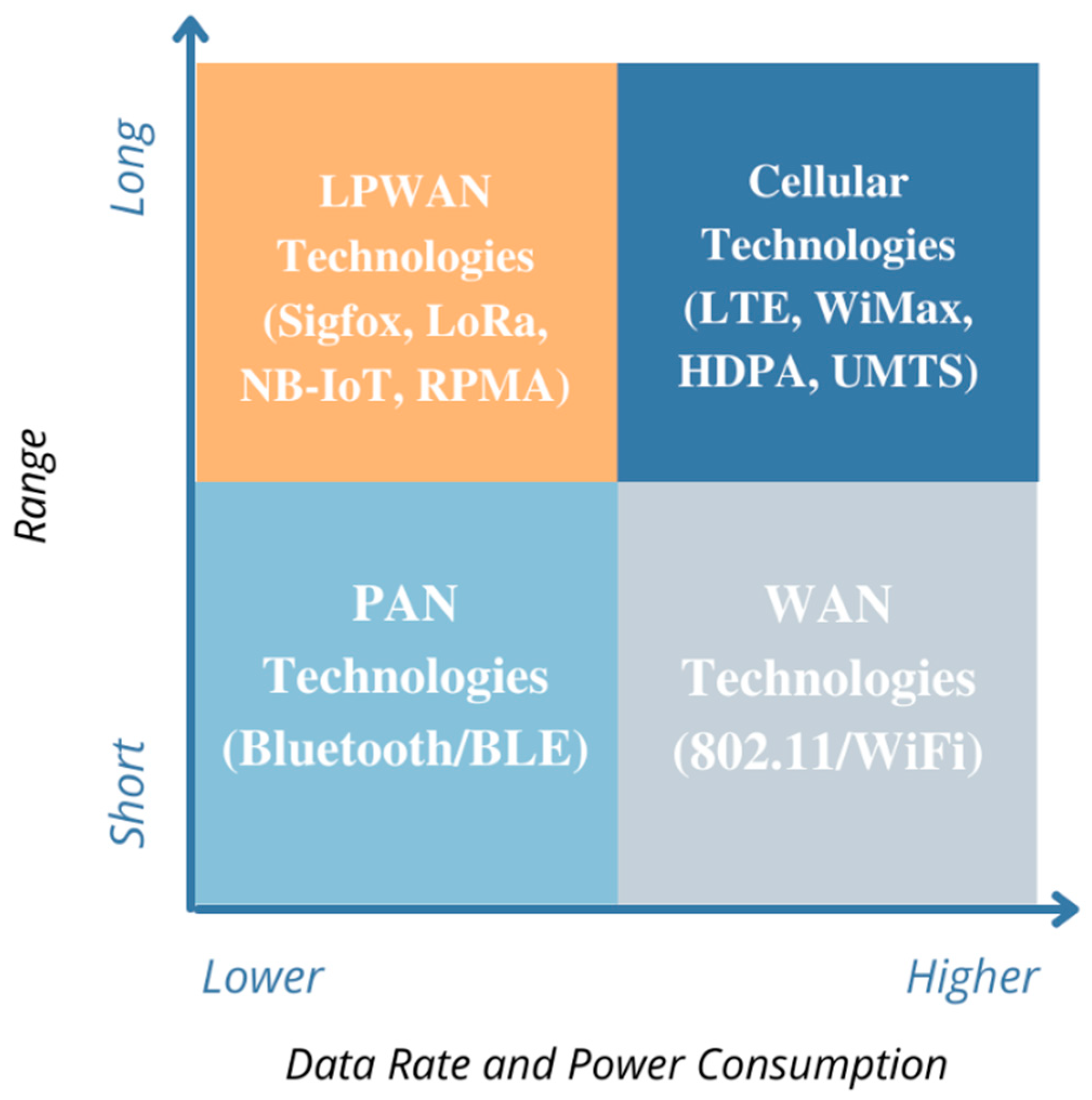

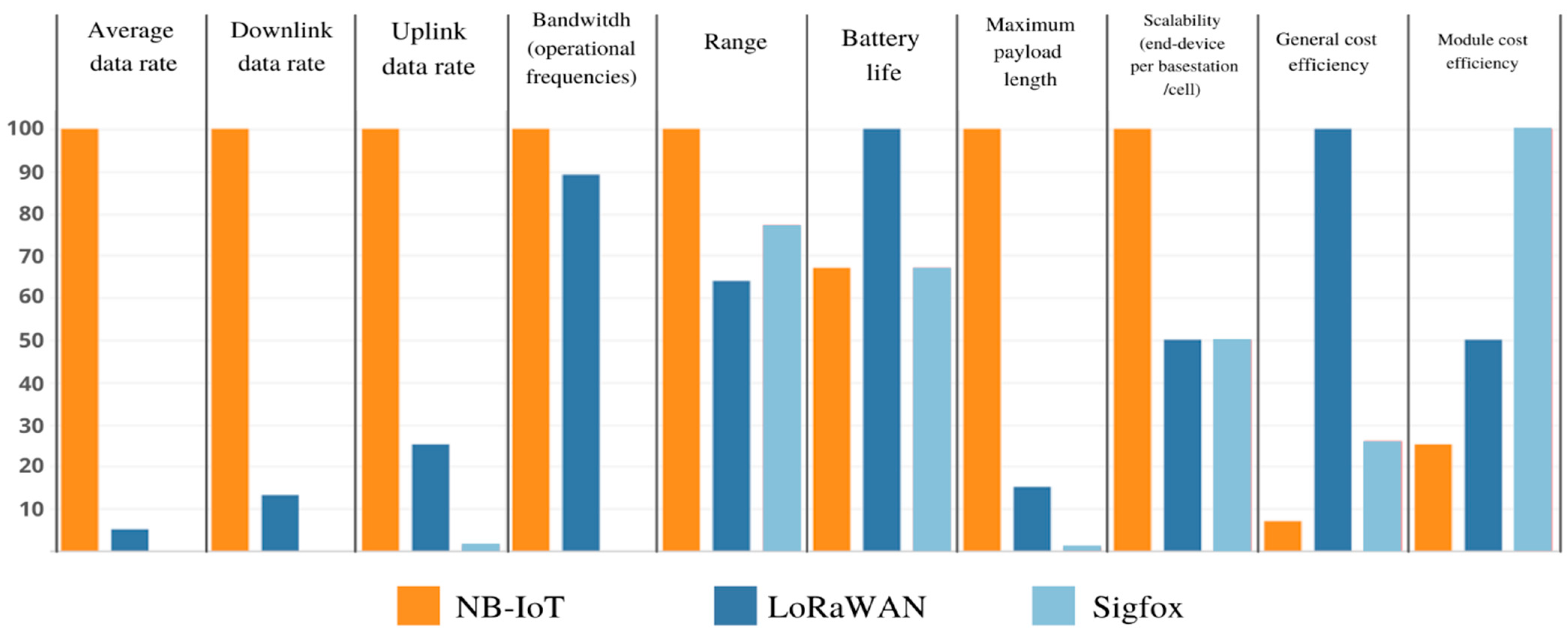

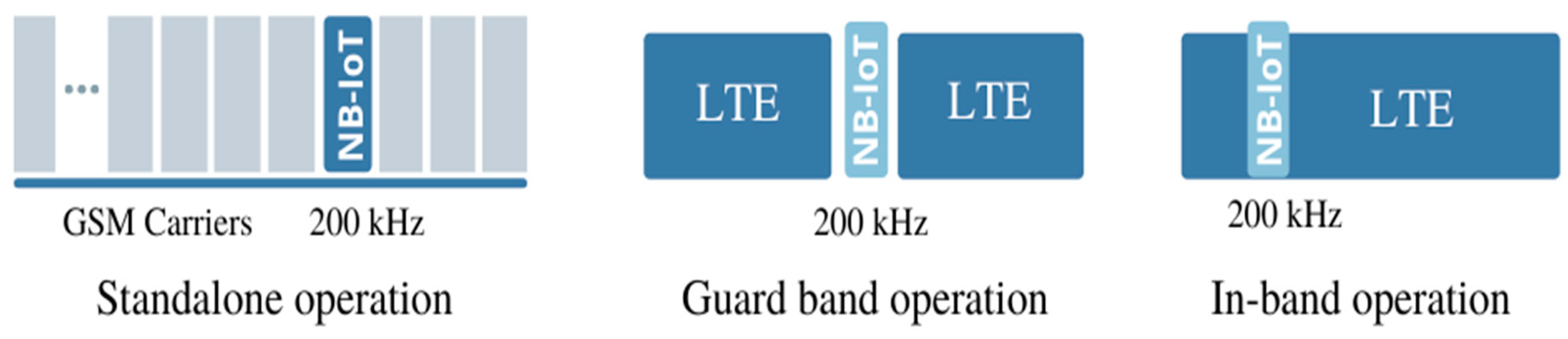
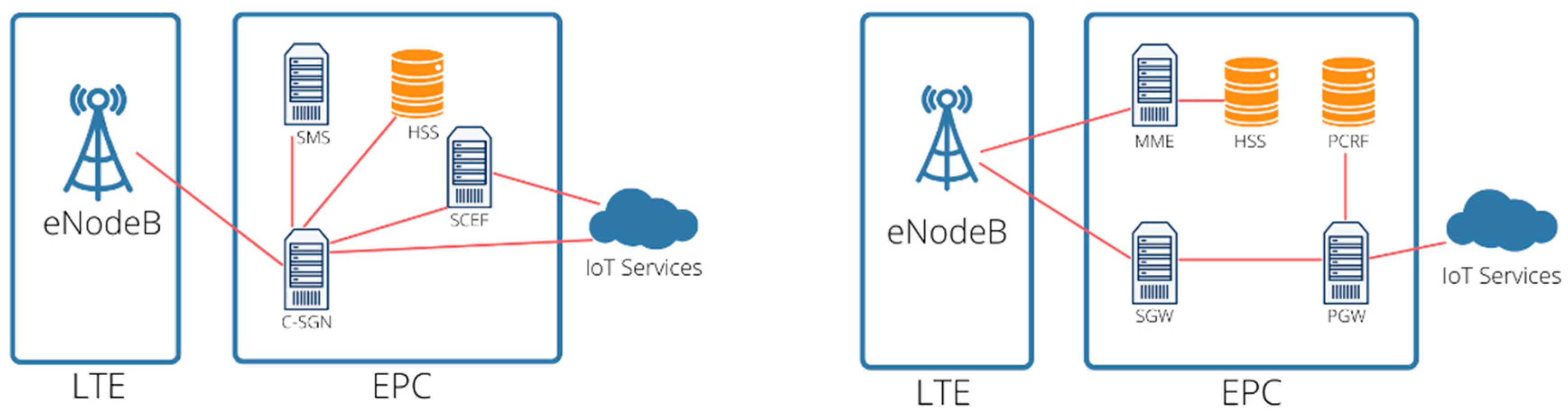
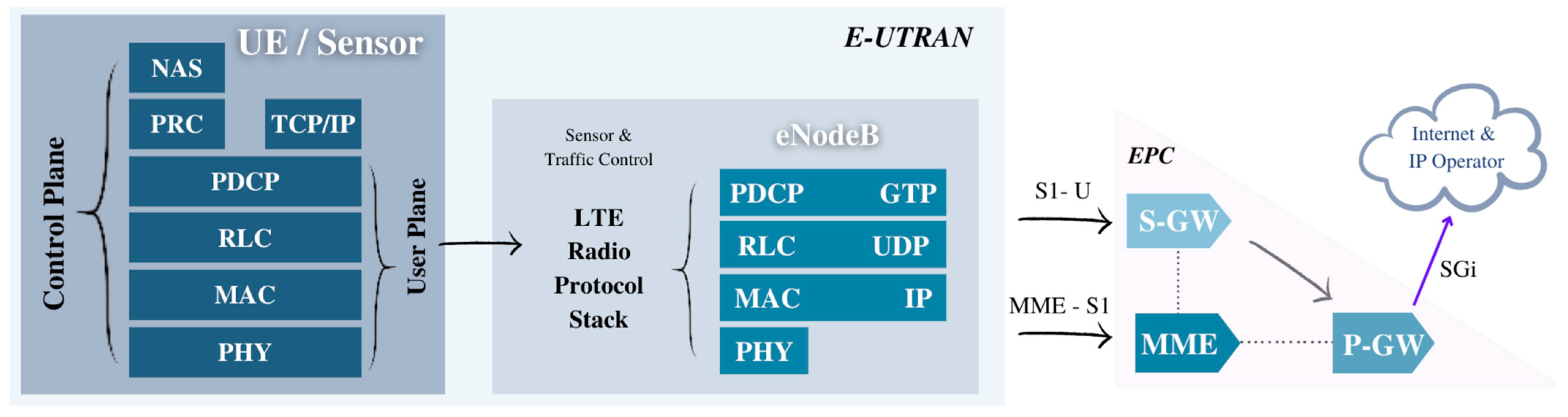
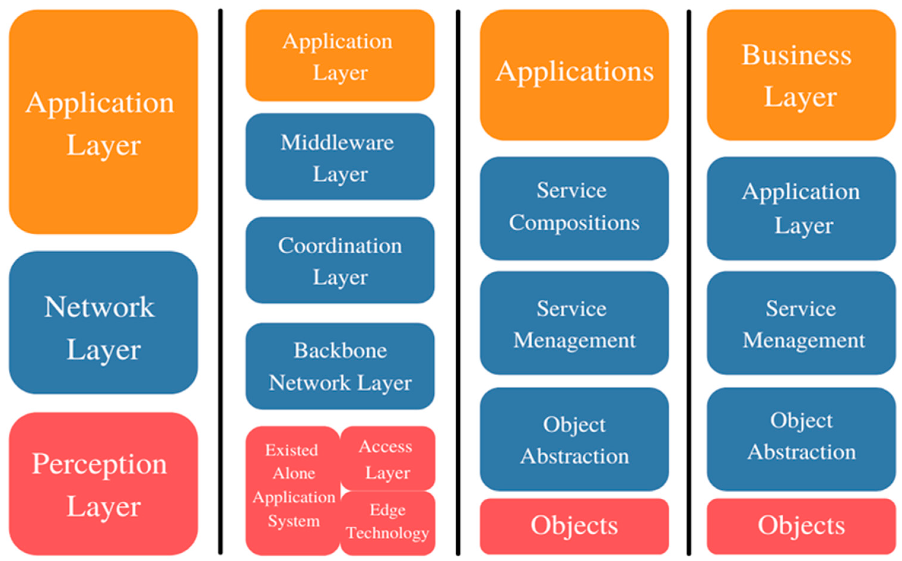
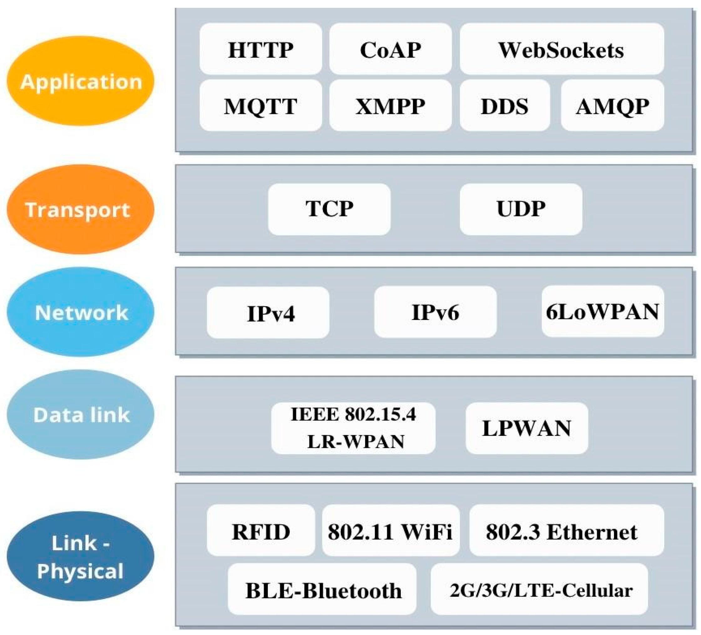
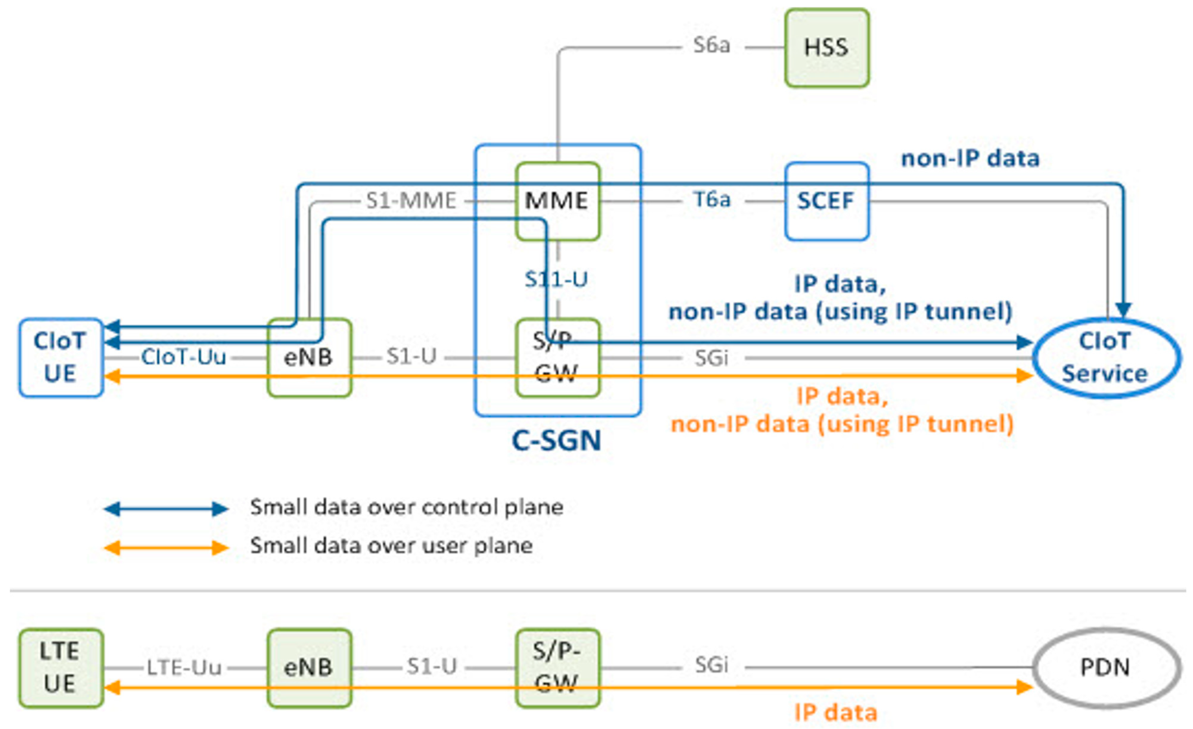

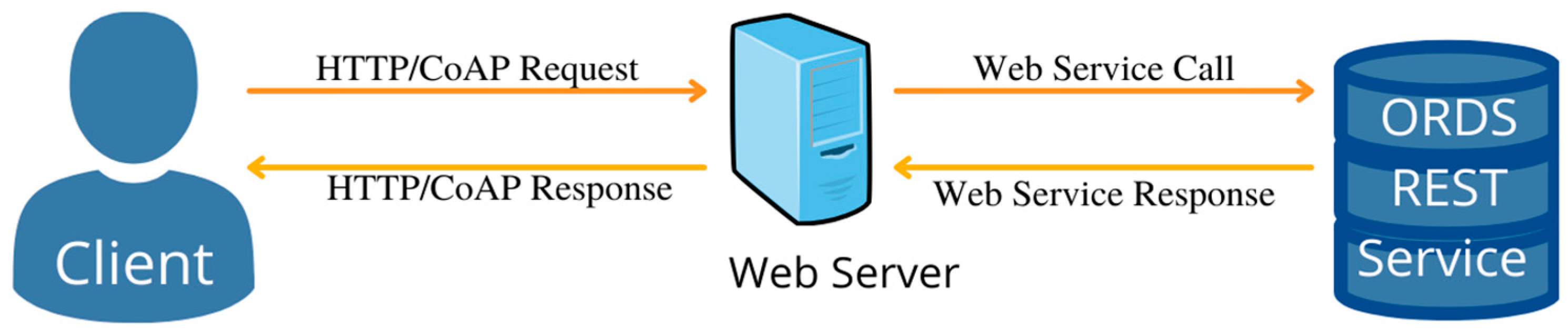
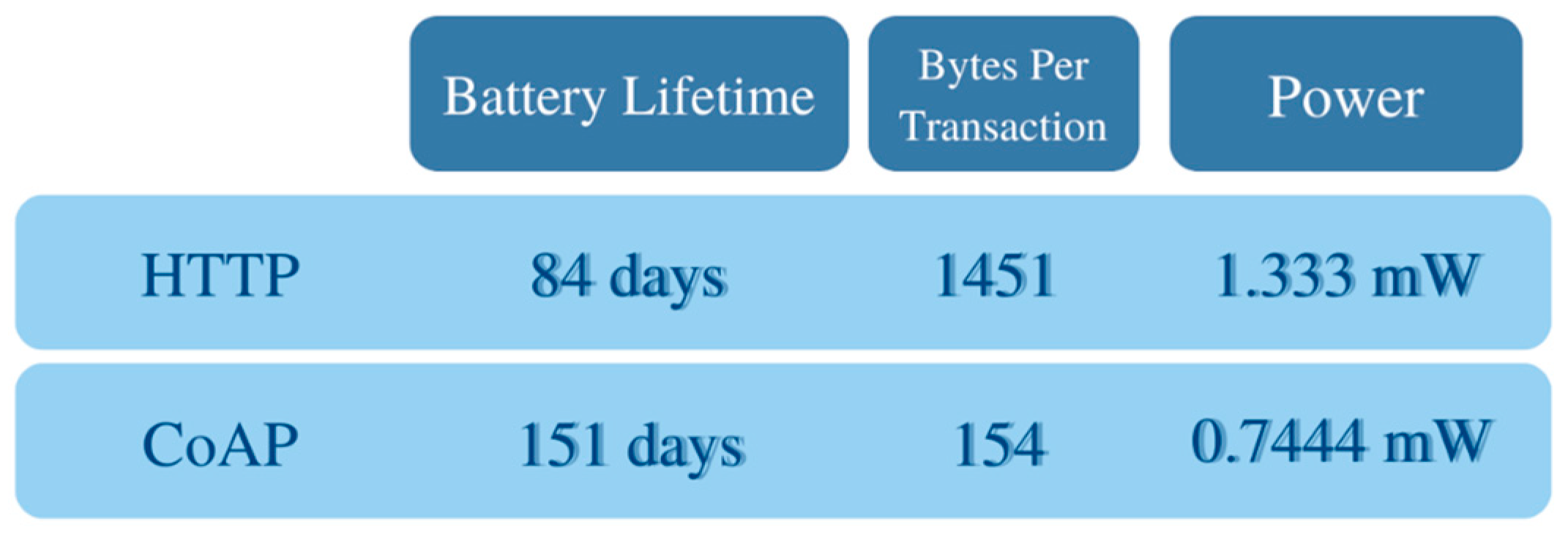
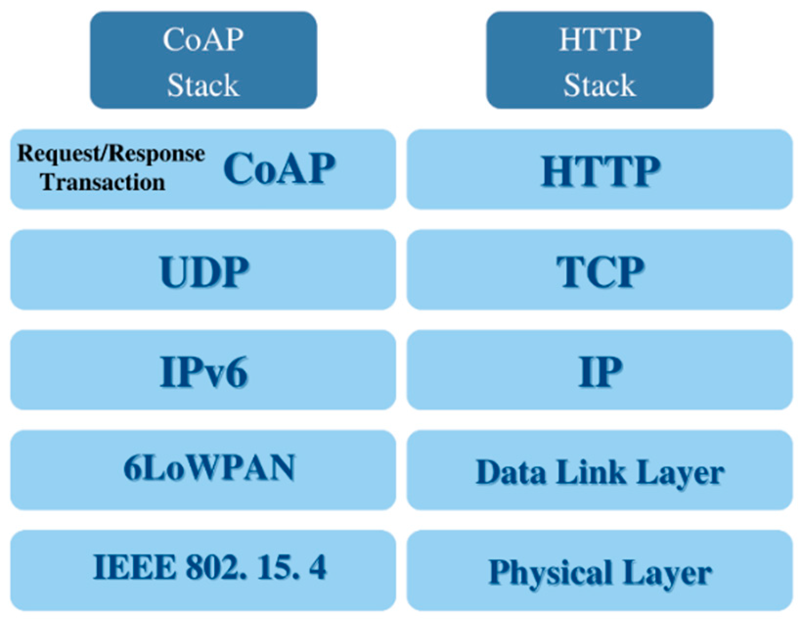
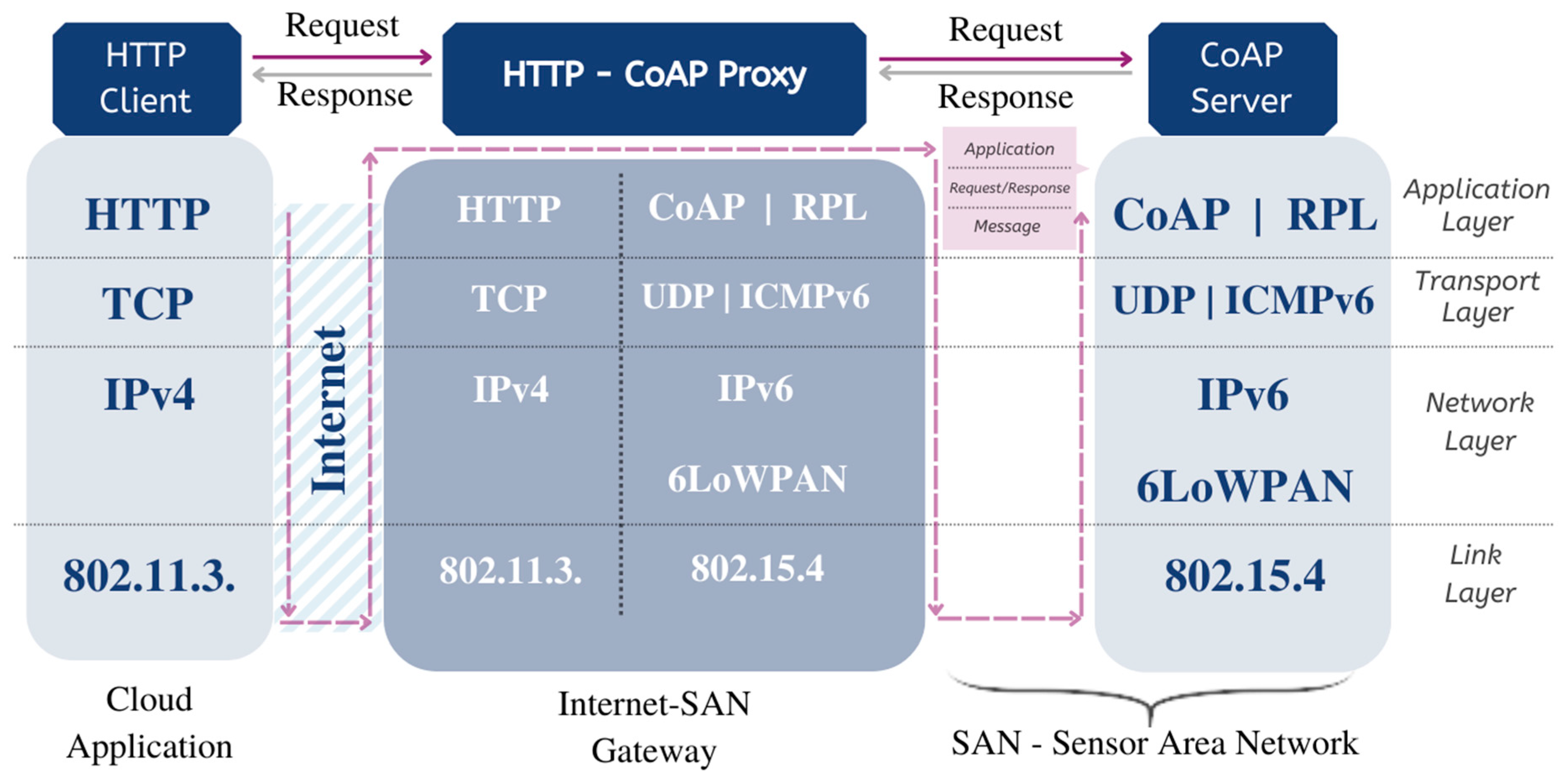
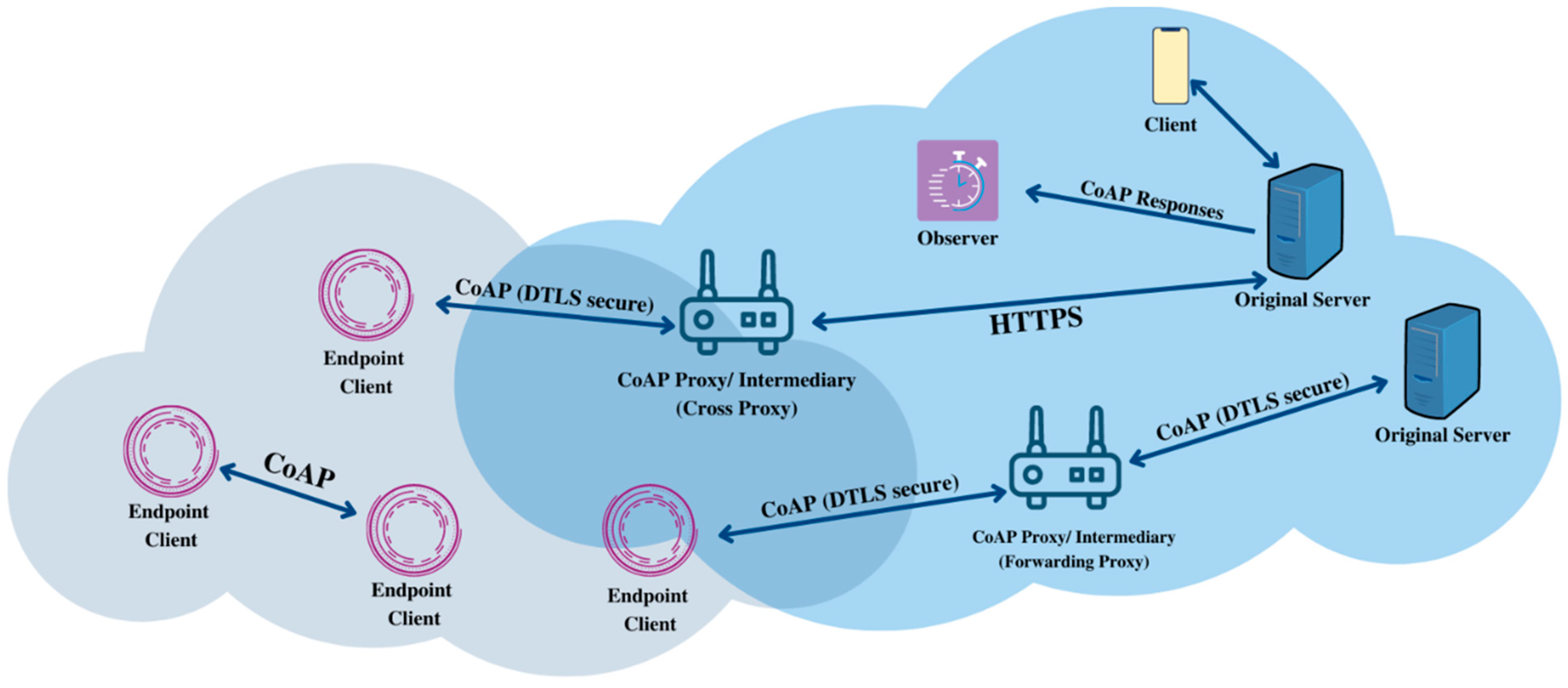
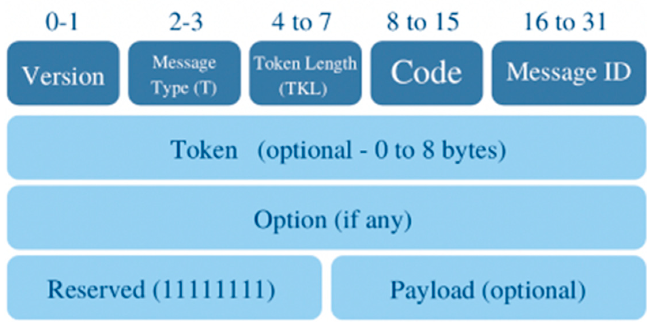
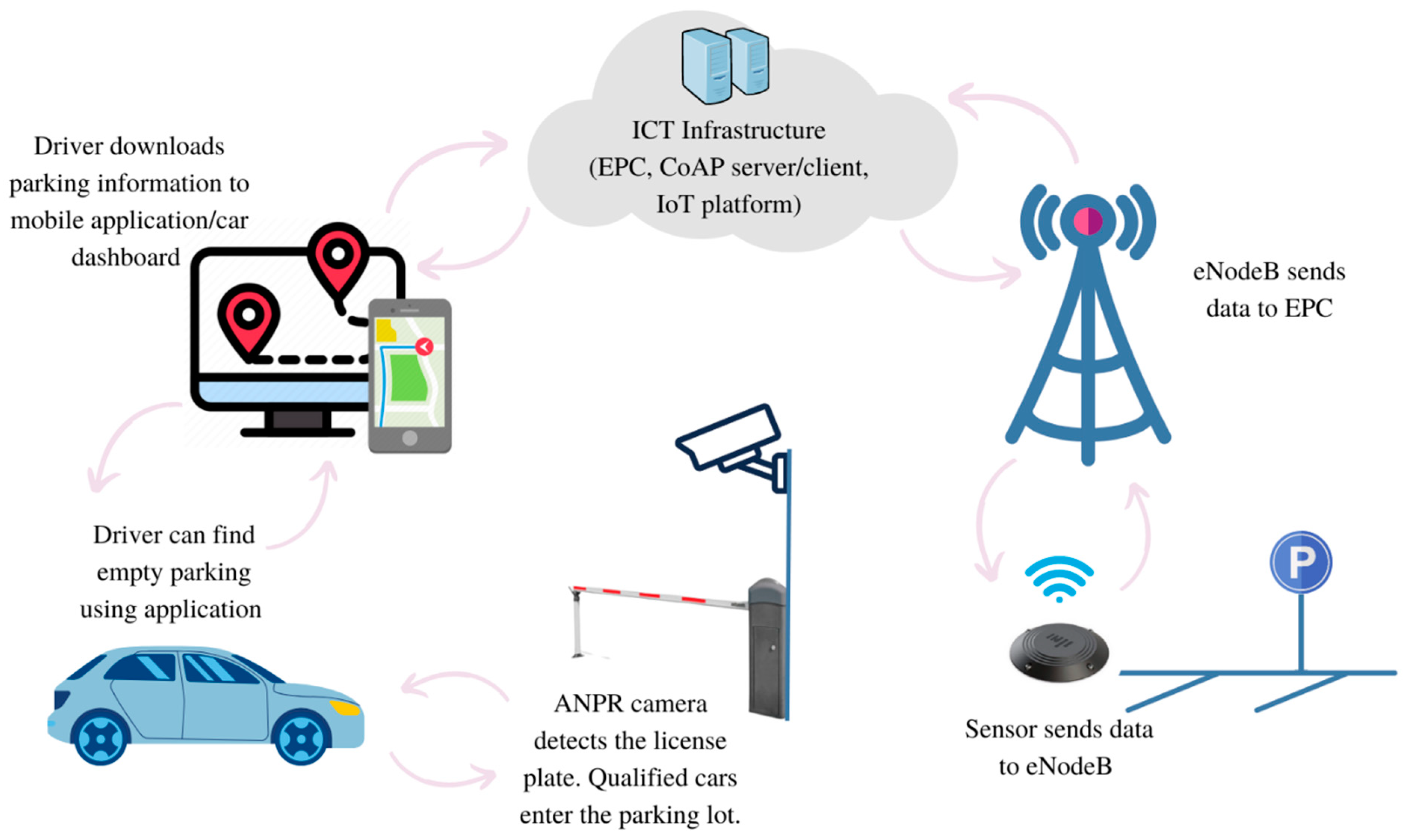
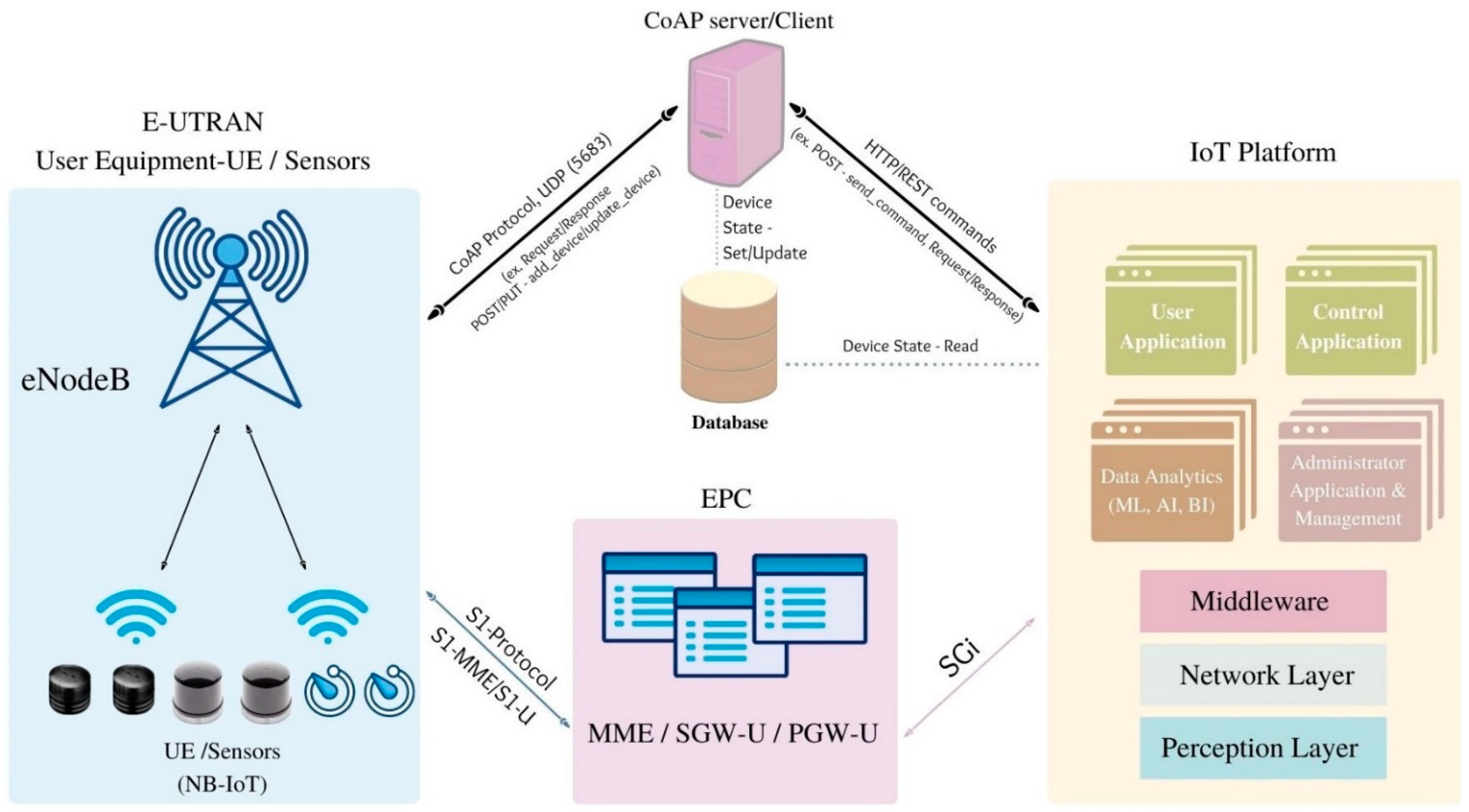
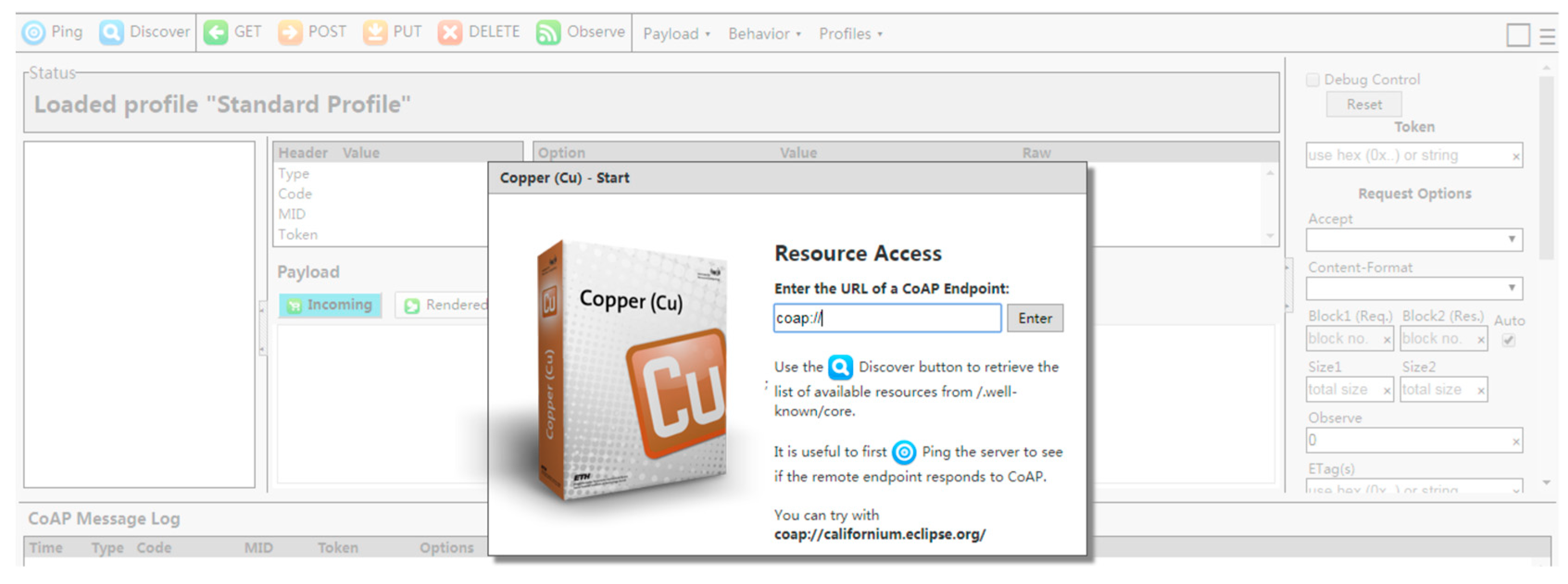
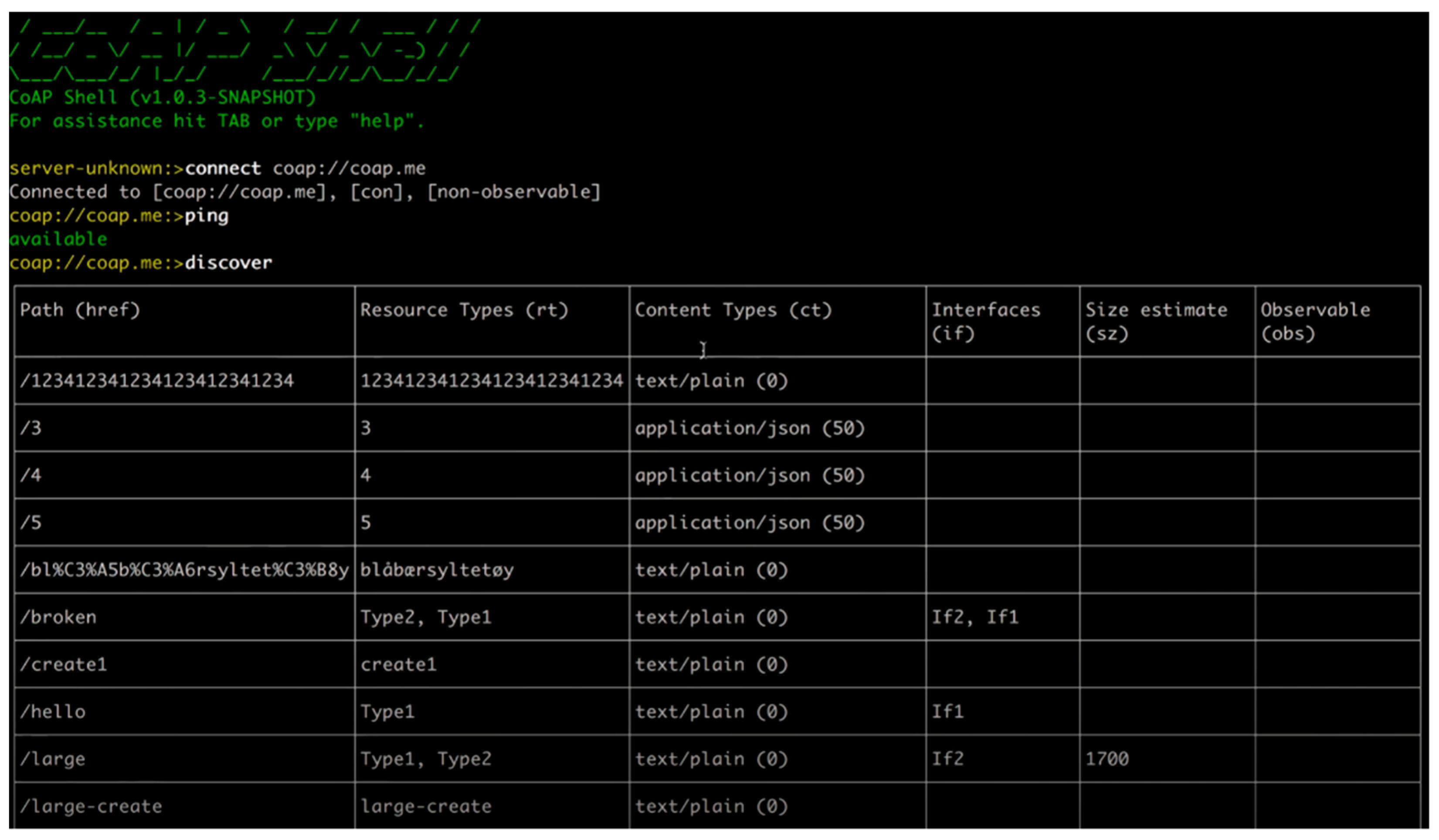
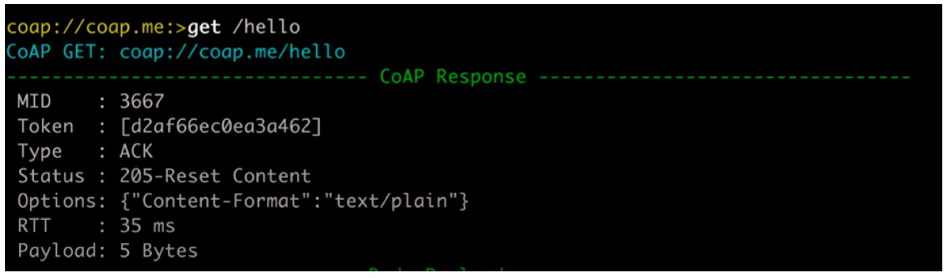
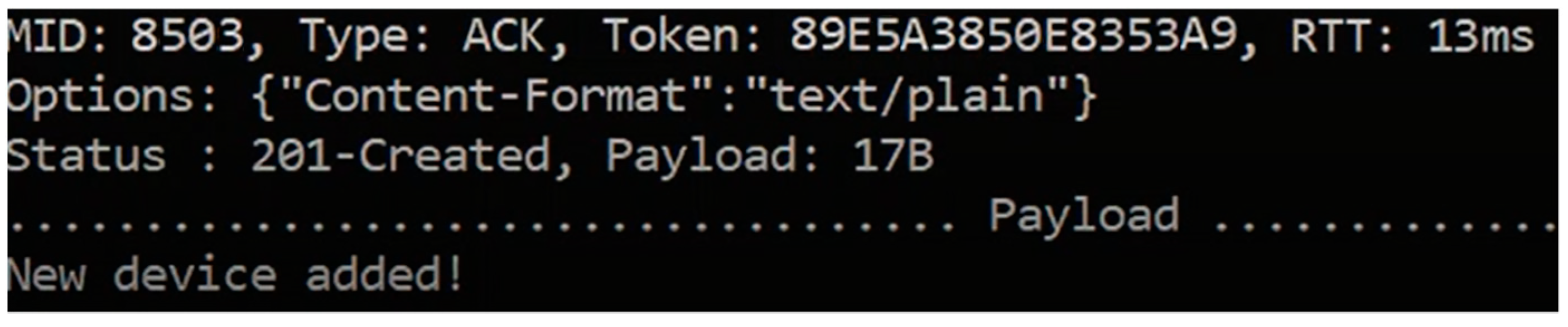
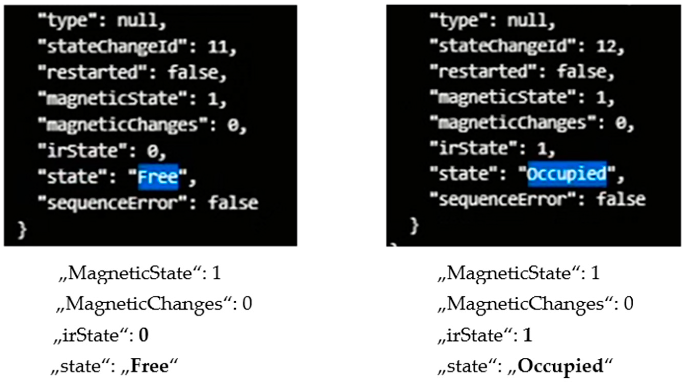

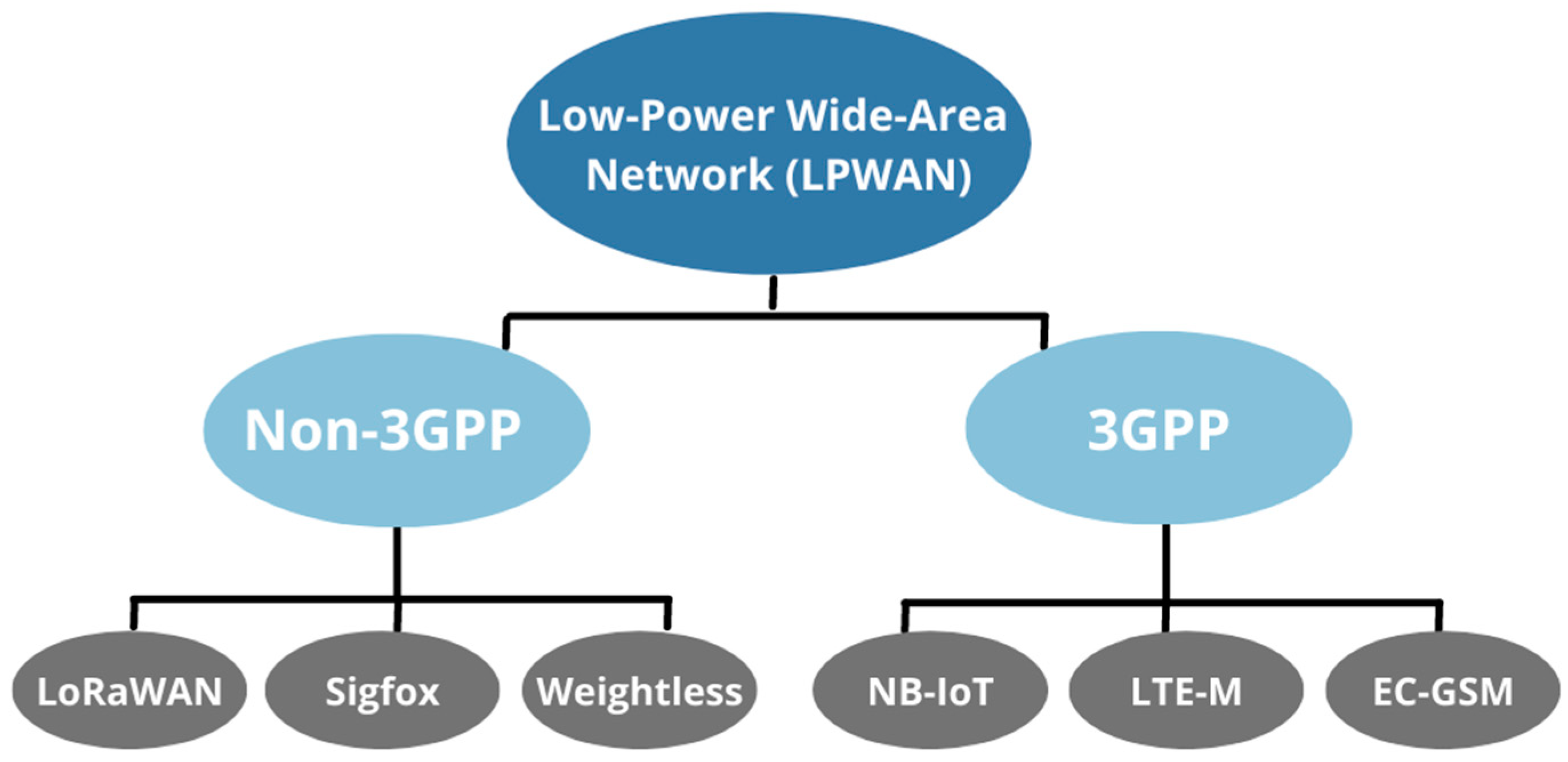
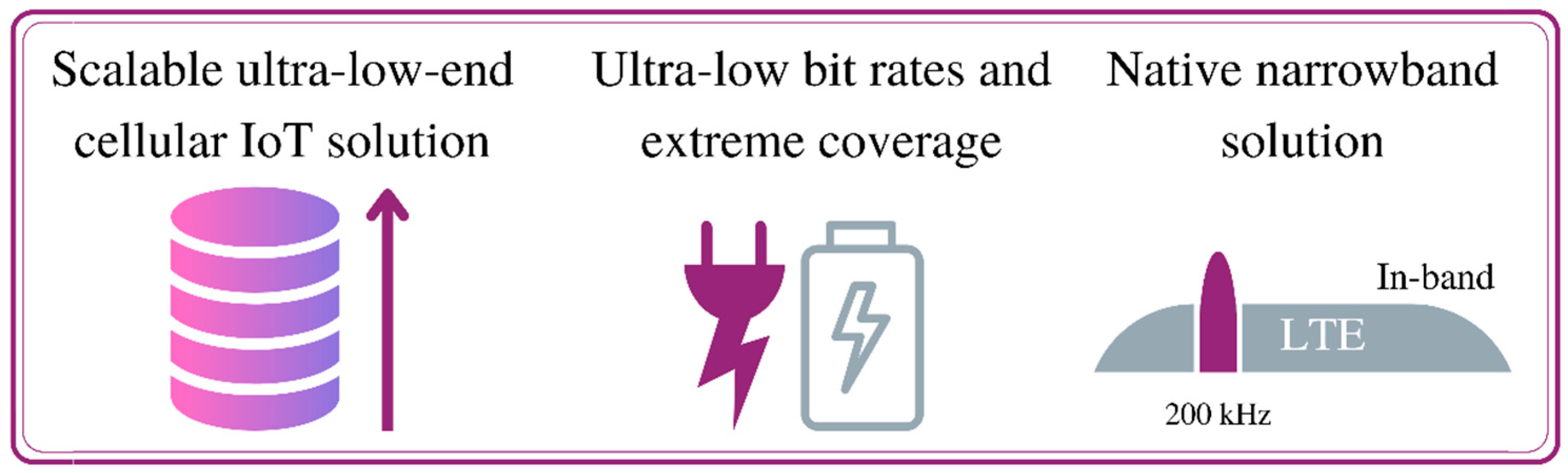
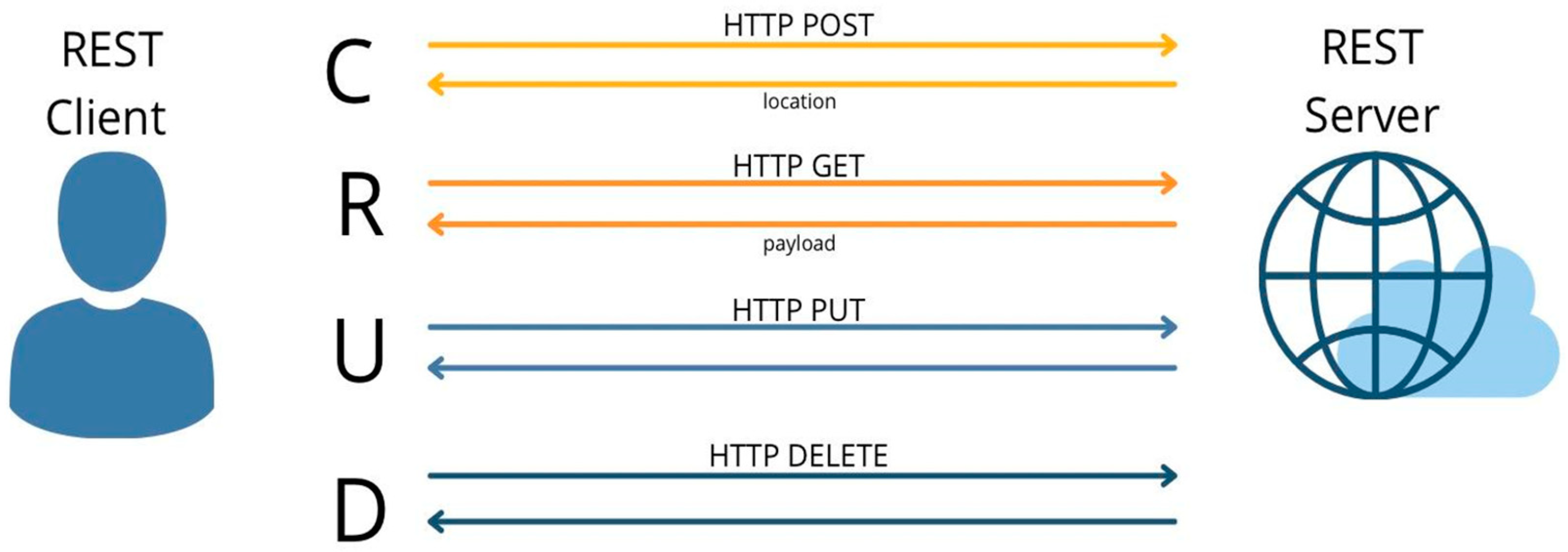