Abstract
Software Defined Networking (SDN) has proved itself to be a backbone in the new network design and is quickly becoming an industry standard. The idea of separation of control plane and data plane is the key concept behind SDN. SDN not only allows us to program and monitor our networks but it also helps in mitigating some key network problems. Distributed denial of service (DDoS) attack is among them. In this paper we propose a collaborative DDoS attack mitigation scheme using SDN. We design a secure controller-to-controller (C-to-C) protocol that allows SDN-controllers lying in different autonomous systems (AS) to securely communicate and transfer attack information with each other. This enables efficient notification along the path of an ongoing attack and effective filtering of traffic near the source of attack, thus saving valuable time and network resources. We also introduced three different deployment approaches i.e., linear, central and mesh in our testbed. Based on the experimental results we demonstrate that our SDN based collaborative scheme is fast and reliable in efficiently mitigating DDoS attacks in real time with very small computational footprints.
1. Introduction
The legacy of distributed denial of service (DDoS) attacks continue to grow in sophistication and volume with attacks breaking the barrier of hundreds of Gbps [1]. DDoS is one of the biggest problem for the reliable operation of the Internet today [2]. One of the major concerns is that performing DDoS attack is extremely simple with websites known as “Booters or Stressers” that offer “DDoS as a Service”. These booters provide cheap services and the costs to perform a series of attacks is typically just a few dollars [3].
Recently, Internet of Thing (IoT) devices (such as printers, cameras, home routers and baby monitors) were used to generate a DDoS attack involving malicious domain name system (DNS) lookup requests from tens of millions of IP addresses [4]. This attack is considered the largest of its kind in history with an unprecedented rate of 1.2 Tbps. The main target of the attack was the servers of Dyn Inc., a company that controls much of the Internet’s DNS infrastructure [5]. Study of recent attacks reveal that with little effort, next generation attack tools would be able to enact DDoS attacks that are thousand times stronger than the ones we see today [6]. A popular defense practice against DDoS is to deploy detection and response mechanisms at the destination hosts due to higher accuracy and cheaper cost. On the downside, destination based mechanisms alone cannot mitigate attack on the paths to the victim and waste resources. This calls for an efficient mitigation strategy to ease out network resources along the transit path of an attack from source to victim.
SDN bring us a new approach to deal with DDoS attacks [7,8,9]. The separation of control and data plane in SDN allows us to write the control logic and instruct the forwarding plane to behave accordingly. This programmability gives us more control of the network traffic which was not possible before the advent of SDN. In [10], Giotis et al. proposed a DDoS mitigation scheme across multiple SDN domains or networks (Domain(s) and Network(s) are used interchangeably throughout this paper). The mitigation process starts from the victim network and propagates along the way towards the source. They extended the border gateway protocol (BGP) to embed the incident report as URIs within BGP signals. This reliance on BGP has some ramifications. First of all, BGP is very complex and hard to master, and any modifications to existing protocol will challenge the deployment. Secondly, the exchange of incident report between adjacent domains is not instantaneous and will only take place after every BGP update interval. Therefore, the report latency will increase with the number of hops between the source and victim of attacks. Further, they do not validate the authenticity of incident reports exchanged among the adjacent SDN domains. This could make the whole infrastructure vulnerable to fake incident reports from malicious domains.
In this paper, we propose a lightweight, efficient and easy to deploy collaborative DDoS mitigation scheme leveraging SDN. We have designed a secure C-to-C communication protocol for SDN-controllers lying in different autonomous systems (AS). This allows SDN controllers to effectively communicate with other controllers in the neighbouring domains and inform them about an ongoing attack. Through this approach, the SDN controllers are able to simultaneously perform the following two tasks.
- Block the malicious flows within the network.
- Inform the neighboring domains/networks about an ongoing attack.
This way we are not only able to successfully mitigate the DDoS attack within the victims’s network but the transmission of attack information along the path of an attack (transit networks) enable us to filter the DDoS attack close to the attack sources. This results in the preservation of valuable network resources along the attack transit path.
Push-back schemes to mitigate DDoS attack along the attack path has been discussed in the research community [11,12]. These schemes add functionality in each router to detect and filter attack traffic and also to notify the upstream routers to drop such traffic [13]. As a result, they require more resources at various levels and the push-back mechanism must be deployed in all the participating network components (routers and switches). The complexity and overhead because of the coordination and communication among distributed components adds serious management challenges. SDN based deployments on the other hand ease the management challenges, where a single controller can manage the coordination among all the network components at the AS level. The proposed C-to-C communication protocol is flexible and it can be easily appended with the best known DDoS detection engines. Further, the protocol itself can use different approaches for deployment. It can be deployed in linear order, peer-to-peer or via centralized scheme to collaboratively disseminate DDoS filtering information.
In order to assess our proposed collaborative DDoS mitigation scheme, we deploy prototype testbeds in our laboratory. We also introduce three different deployment approaches i.e., linear, central and mesh in our testbed. Scalability and efficiency pose the main challenges because of the number of ASes in the routing systems globally. Our evaluation results are quite promising and demonstrate the effectiveness, flexibility and scalability of the proposed approach.
An early version of this work appeared as a workshop paper [14]. In this paper, we have added significant new results with different hop levels. We also demonstrated performance of global dissemination of attack definition with the central deployment approach along with CPU and memory utilization.
2. Related Work
In this section we highlight relevant research work done in the domain of DDoS defense with SDN (other than [10], discussed in Section 1). This work can roughly be divided into DDoS defense mechanisms against the core SDN infrastructure and the approaches that leverage SDN against DDoS attacks [15].
2.1. SDN Mechanisms against DDoS Attacks
In [16], the authors have utilized Self Organizing Maps (SOM), an unsupervised artificial neural network trained with features of the traffic flow, to classify the network traffic flows as either normal or abnormal. They extended NOX controller and monitor registered switches during predetermined time intervals to retrieved information from the flow of interest. This sample information is then passed to the SOM module that classifies the traffic as normal or attack.
Reference [17] proposed a network reconfiguration scheme using SDN against an attack mounted by botnets. They maintain a pool of public IP addresses and in case of a possible DDoS attack, the server redirects the protected service to a new set of IPs by leveraging the central and dynamic network management offered by the SDN paradigm. A similar redirection approach is employed in [18]. However, instead of redirecting services to new IP addresses, they identify the attack traffic and re-route it away from the victim to alternate routes or sinkholes.
In [19], the authors introduced a use case of SDN-based DDoS attack mitigation system to provide an autonomous and prompt configuration for suspicious network traffic. This work in its current form is very basic without any proof of concept and evaluations.
Bohatei [20] proposes a flexible DDoS defense system that leverages NFV capabilities to elastically vary the required scale (attack volume) and type (e.g., SYN proxy vs. DNS reflector defense) of DDoS defense. Bohatei steers the suspicious traffic through the defense strategy graphs which are based on the packet counts and predefined suspicious behaviors.
In [21], the authors used a combination of SDN and machine learning techniques to detect and block amplification reflection attacks (DrDoS). The OpenFlow switch copies the traffic to the detection agent, which applies the support vector machine (SVM) method to classify the packets as malicious or non-malicious. On detection of malicious behavior, the detection agent notifies the controller to block the malicious packets.
In [22], the authors used sFlow with security-centric SDN to effectively detect and mitigate DNS amplification attack. If the incoming traffic contains a matching request Query ID in the flow records, it is classified as a normal DNS response, otherwise, it is marked suspicious, since no query was initiated in the first place. Marked flows are then forwarded to the SDN controller for mitigation purpose.
Floodlight based guard system (FL-GUARD) [23] proposed a three step approach against a DDoS attack. First, they apply dynamic IP address binding to solve the problem of IP spoofing, next they use SVM algorithm to classify attack traffic, and finally they take advantage of the centralized controller to block attacks at the source port.
2.2. DDoS Defense against SDN
Belyaev et al. [24] proposed a two-level load balancing solution in SDN networks to increase survival time of a system during DDoS attack. Their main work is load balancing and in doing so they do not mitigate DDoS attack but they were able to increase the survival time by dividing the load.
Dao et al. [25] proposed a hard timeout mechanism to phase out fake flow table entries created by an attacker to clog switch-controller communication channel and overflow the TCAM memory of a switch. The timeout is explicitly applied to arbitrary infrequent flows for error or DDoS packets whose sole purpose is to overwhelm the capacity an OF-switch.
StateSec [26] employs stateful SDN in the context of DDoS defense and delegate local processing to switches. Switches directly handle traffic monitoring of pertinent features (e.g., IP source and destination, port source and destination) by using stateful programming, thus reducing the computational burden on the controller. The precise results are then fed to an entropy-based algorithm for attack detection at the controller. This work in its current form is very basic without any extensive evaluations.
2.3. Collaborative DDoS Mitigation
FireCol [27] present a collaborative system at the ISP level to detect flooding based DDoS attacks as close as possible to the attack source(s). Multiple IPSs form an overlay networks of protection rings around subscribed customers and collaborate by computing and exchanging belief scores on potential attacks. The attack is measured based on the overall traffic bandwidth directed to the customer compared to the maximum bandwidth it supports.
CoFence [28] proposes a collaborative DDoS defense mechanism among NFV-based peer domain networks. CoFence allows domain networks to share resources with other peers based on a reciprocal-based utility function. This enables domain networks under DDoS attack to efficiently redirect excessive traffic to other collaborating domains for filtering.
CIPA [29] is an artificial neural network based collaborative intrusion detection system, deployed as a virtual network over the substrate of networks. CIPA disperses the computation power to the programmable switches of the substrate. The neural network disperses across the switches to function like an integrated IDS/IPS and give the system a global view to detect distributed attacks.
3. System Design and Architecture
Collaborative DDoS mitigation requires multiple SDN domains networked together as depicted in Figure 1. Each domain is a complete AS with egress and ingress routers. Any single autonomous system may be comprised of multiple SDN controllers which communicate with each other via our proposed C-to-C protocol. At the border of any AS sits SDN controllers that are capable of communicating with the neighboring AS’s controllers to transfer attack definitions (Attack definition basically consists of the malicious IP addresses that are exchanged in the payload of C-to-C protocol). These ASs can roughly be divided into a Source Domain, an Intermediate Network Domains and a Destination Domain.
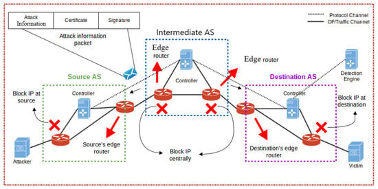
Figure 1.
High-level Architecture of Collaborative DDoS framework.
The source network is what the attack traffic is initiating from. The intermediate network(s) is comprised of multiple SDN domains connected with each other. The destination network(s) is the one that the victim is residing in. Attack traffic initializes from the source domain(s). It passes through intermediate networks to reach the destination network.
In this paper, we have leveraged SDN to effectively mitigate the DDoS attack closest to the source. Our primary assumption in this work is that a detection engine will inform our SDN controller about possible attack information based on which we will mitigate the DDoS attack. This detection engine may consist of very effective and sophisticated detection mechanisms, like the one proposed in [30], which can be both internal as well as external to the AS. In the following subsections we discuss the internal component architecture of the controller. Furthermore, we have elaborated the payload structure of the C-to-C protocol and summarized the overall collaborative DDoS mitigation work flow.
3.1. Controller-to-Controller (C-to-C) Protocol
Figure 2 depicts a typical packet sent from the detection engine to the SDN controller. A typical C-to-C packet sent by the detection engine to the SDN controller is comprised of three sections i.e., data, certificate and signature (see Figure 2). The data section contains a list of IP addresses and the corresponding action that must be taken. The certificate section contains a certificate along with the public key. The signature section contains a message digest signed with the private key of the attached certificate.

Figure 2.
Payload structure of C-to-C protocol.
3.1.1. Data Section
This section contains all the information that needs to be communicated, which in our case are typically a list of IP addresses along with their statuses. Figure 3 shows a raw representation of the data contained in JSON format. The JSON object is self-descriptive. We have a list of IP addresses that are needed to be blocked, or if an IP was previously blocked mistakenly, then the status helps in unblocking it.

Figure 3.
Payload of C-to-C protocol with attack definitions.
3.1.2. Certificate Section
The certificate section is comprised of a certificate attached by the communicating system to authenticate its legitimacy.
The idea of certificate chaining is not new and it is heavily used in day to day communications, e.g., in authenticating the DNS records, in client to server communication and server to server communication. There are two types of certification authorities (CAs): root CAs and intermediate CAs. In order for a certificate to be trusted, that certificate must have been issued by a CA that is included in the trusted store. In our system, a trusted store is a directory containing root or intermediate certificates and other private keys of the user. There is no particular directory specified in Linux for trusted store. We have created our own in the POX controller folder.
If a certificate presented by a neighboring controller is not issued by a trusted CA then the certificate of the issuing CA is checked to see if the certificate of the issuing CA was issued by a trusted CA and so on until either a trusted CA is found (at which point signature is verified and flows are installed) or no trusted CA can be found (at which point the whole payload is dismissed).
3.1.3. Signature Section
This section contains a message digest signed by the private key of the certificate attached. This helps in verifying the authenticity as well as the integrity of the attack definition and its sender.
3.2. Controller Modules
We have written different programs that run on POX [31] as stand-alone modules. These modules allow the controller to perform different functionalities such as installing flows, listening for attack definitions from neighbouring controllers, validating the signature of attack definitions and propagating the attack definitions to other controllers. The modules are further discussed in the following sections (also see Figure 4).
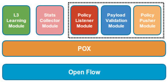
Figure 4.
Component Architecture of controller.
3.2.1. Policy Listener Module
This module runs a simple lightweight server program on the controller that listens on a predefined port for attack definitions received from neighboring controllers. On receiving an attack definition, the module verifies the payload via Payload Validation Module using the embedded certificate. Upon the successful verification, all the attack definitions are written on a CSV file and the L3 Learning Module is made aware of the updated policies. The L3 Learning module then refreshes the policies by installing new flows from the updated CSV file. This module also calls the Policy Pusher Module to forward the flows to the neighboring controller.
3.2.2. Payload Validation Module
This module validates the certificate and verifies the signature of the payload before the payload is further processed and flows are installed into the individual nodes (i.e., switches or routers). The certificate is validated via chain of trust. A root certificate of the CA is present in the trusted store. The certificate is validated against the trusted CA. Upon the successful validation of the certificate, the signature of the payload is validated for checking the integrity of the message. The IP addresses contained in the payload are forwarded to the connected nodes upon successful signature verification.
3.2.3. Policy Pusher Module
This module pushes the policies (containing the new attack definitions) to the neighboring controllers. The Policy Listener module informs the Policy Pusher module to update the policies locally upon the successful verification and forwards the attack definitions.
3.2.4. L3 Learning Module
This module derives most of its functionality from POX’s out of the box forwarding module named L3_learning. It is a simple layer 3 learning module that provides connectivity between the nodes via the nodes they are connected with. L3_learning module handles the ’packet in’ event. The module maintains a list of bindings ports of switch with the MAC address of the connected machines. Upon arrival of a new packet, it first looks into its list for an already existing binding. If a binding is found, the packet is forwarded to that port along with the flow which is installed on the switch for any number of subsequent packets. If no binding is found, the module instantiates an ARP request. Upon receiving ARP reply, the port and MAC address binding is saved into the list and the packet is forwarded to the destination port along with the flow. Along with the connectivity, it installs policies received to block the attack traffic. Whenever new flows are installed, the policy listener module informs the L3_learning module. The L3_learning module then flushes all the flows installed on the nodes and installs negative flows blocking malicious traffic.
3.2.5. Stats Collector Module
This module collects information like number of packets/second passing through a particular domain, active flows installed in a network and traffic passing in Mbps, etc. This module is specifically used to collect evaluations and results when the proposed mechanism is deployed on several test beds.
3.3. Work-Flow of Inter AS Collaborative DDoS Mitigation
The complete work flow of the Collaborative DDoS mitigation is summarized as follows.
- The detection engine communicates with the SDN controller via C-to-C protocol and forwards a list of malicious IP addresses in the form of an attack definition.
- The SDN controller first validates the communicating server by going through the following steps:
- (a)
- A certificate is retrieved from the payload.
- (b)
- The Payload validation module validates the certificate via a root certificate of the issuing certification authority present in the trusted store.
- (c)
- Once the certificate is authenticated via root chaining, the signature of the message is validated.
- (d)
- Upon the successful validation of the signature, the payload is processed further or it is discarded.
- The IP addresses present in the payload are then written to a policy file and L3-Learning module is informed about the updates in the policies.
- The L3-Learning module then reads the updated policies from the policy file.
- The L3-Learning module then installs the new policies on each connected node.
- As a result of the new policies, malicious flows are blocked. Any previously blocked flows can be allowed depending upon the improved detection.
- The SDN controller then forwards the policies to the neighboring controllers via Policy Pusher Module.
- The neighboring SDN controllers performs the same steps starting from step 2 to 7.
3.4. Protecting Controllers against DDoS
C-to-C protocol facilitates selective communication between authorized controllers with valid signatures on the payload. This enables effective filtering of unnecessary traffic from unknown source(s) and limits the effect of DDoS attack directed towards the controller at the first place. Still attackers can try to launch a DDoS attack against a controller in an ISP (or AS), however, a DDoS attack against a controller is synonymous with an attack against any host/server within an ISP. Our proposed scheme will be effectively applicable in this scenario as well.
4. Testbed and Evaluations
We divide our testbed into three different networks i.e., Source, Intermediate and Destination network(s). We use Mininet [32] to emulate the networks with POX [31] as the controller platform. In our testbed, OF-switch are also used to simulate the behavior of an edge router in an SDN network to filter the traffic as per policy. All the Mininet instances emulating different networks are connected via GRE tunneling. The role of each network in our testbed is discussed below.
The Source network is the one that generates both legitimate and attack traffic. We used three nodes in the source network out of which two generate attack traffic while one node is the legitimate one.
The Intermediate or inter-connecting networks are multiple Mininet networks connected via GRE tunneling. They are autonomous networks running their own topologies and also act as the transit networks to route the traffic between source and destination. They can be treated as different autonomous systems within the same ISP or different autonomous systems in different ISPs. Since they are Mininet emulated networks, they contain SDN controllers running on POX framework. The SDN allows us to communicate with these networks during the process of mitigation and to install the blocking flows to restrict the attack traffic passing forward, hence the load of mitigation is not solely on destination network, instead it is distributed on the whole network and it will gradually find its way towards the source of the attack.
The Destination network is also a Mininet network comprising a victim node that is the destination for both legitimate and attack traffic generating from the source network(s). Initially the destination host fulfills all the requests coming from the source network(s) without any distinction between legitimate and malicious traffic. However, once the destination network is made aware of the malicious traffic, it starts blocking the malicious traffic and subsequently informs the neighboring networks.
For the most part of our evaluations (mentioned otherwise), each node in our testbed consists of 2.60 GHz Intel core i5 CPU, 8 GB RAM, 500 GB HDD and 1 Gbps Ethernet card. We use Scapy [33] to generate ICMP packets with varying payloads for both attack and legitimate traffic targeted towards the destination.
Since detection is not within the scope of our work, we have simulated a node as a detection engine that feeds malicious flows to the destination network in order to mitigate the attack. It can reside in any of the above networks or it can be in a different network. Furthermore, there is no restriction that this node should also be running within an SDN network. It can be in a legacy network. All that is required from this node is that it speaks the same C-to-C protocol as defined in the above section to properly authenticate itself and provide the attack definitions.
4.1. Deployment Approaches
We used three different approaches to deploy our testbed. As a test bed, we have taken three approaches shown in Figure 1, Figure 5 and Figure 6. The basic difference between the approaches is how the policies (attack definitions) are distributed. These approaches are briefly discussed as follows.
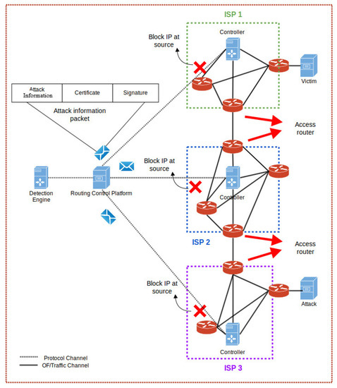
Figure 5.
Centralized Policy Distribution.
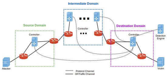
Figure 6.
Mesh Connectivity for Direct Policy Distribution.
4.1.1. Linear Approach
This is the regular implementation discussed in the above section with architectural details (Figure 1). This approach comprised of all the participating networks i.e., Source, Intermediate and Destination networks connected with each other in linear fashion. A third party detection engine (similar to HADEC [30]) feeds the attack definitions into the destination network, which then forwards them to the neighbouring network and this process continues until the definitions reach the source.
4.1.2. Centralized Approach
In this approach (see Figure 5), there is one Central Control Platform that handles attack definitions from all the connected networks. Upon successful verification, the platform then forwards the attack information to the connected SDN controllers. The SDN controllers upon receiving the attack definitions install the flows defined in the policy after verification check. This approach is helpful in preventing hop-by-hop dissemination of attack definition, specially in scenarios where a huge amount of traffic is being handled by SDN controllers. Moreover, in this approach the flows installed can be targeted depending upon the destination address. As a result, not every SDN network has to install all the flows. The central approach only forwards the relevant flows to the intended SDN controller hence saving the TCAM memory of OpenFlow switches.
4.1.3. Mesh Approach
In this approach, any single network deploys a mesh connectivity with existing networks (see Figure 6). This enables any single network to forward the received attack definitions directly to all the connected networks, instead of pushing the attack definitions linearly one by one to its neighboring network. This way the mitigation process is very fast.
4.2. Bootstrapping
In order to effectively bootstrap the proposed scheme, we have to consider the accessibility to neighboring controllers and pre-hand knowledge of the CA. In the case of peer-to-peer deployment, a controller in an AS will follow the peering agreements. Just as any edge routers are configured with the accessibility information of neighboring AS’s edge router, the controller’s in peer ASs will be configured with the accessibility information (IP, port). In the centralized approach, the AS can publish a list of authorized controllers in the Central Control Platform. This approach is very simple, yet very effective and it is successfully being used by Sender Policy Framework (SPF) [34] (an IP based email authentication mechanism with over 7 million registered domains). The knowledge of CAs is part of controller’s configuration; this approach is successfully used in DNSSEC and all the browsers that have pre-installed certificates of more than 600 root CAs and 1200 intermediate CAs.
4.3. Effect of Deployment Approaches on Attack Mitigation
We performed different experiments to analyze the behavior of attack mitigation under different deployment approaches (linear, central and mesh). We would like to emphasize that the core focus of the proposed collaborative scheme is mitigation of DDoS along the attack path and this scheme can be flexibly appended with any effective detection algorithms. We obtained some promising results that give us insight about the potential problems that our proposed architecture is capable of solving.
4.3.1. Linear
For the Linear approach, we set up two testbeds with four networks (one source, one destination and two intermediate networks) and eight networks (one source, one destination and six intermediate networks) connected in a linear fashion. The choice of two intermediate networks helps in representing short routes, whereas, six intermediate networks give us relevant ISP settings that would work in practice. This is because the average length of AS paths over time, as seen by the RIPE NCC Routing Information Service (RIS) route collectors, for IPv4 networks is fairly stable at 4.3 AS-hops [35].
In the experiments, the source network generates approx. 21,960 packets per second out of which only 4392 packets are legitimate and the remaining 17,568 packets are malicious. For the sake of simplicity, we have assumed that none of the intermediate network is generating its own traffic. Hence, the only traffic passing through the intermediate networks is coming from the source network.
For the first experiment, we used LAN settings with no delays between different SDN domains. Furthermore, we used attack definition with 1 K IP addresses to keep the processing delay minimum. The results generated via this setup are shown in Figure 7. The graphs are between the data flowing from source to destination and the time it takes to mitigate the attack.
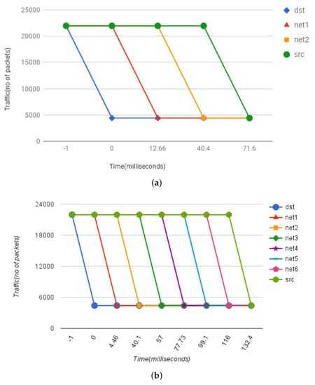
Figure 7.
Mitigation Effect in LAN Setting: Shows the data flowing from source to destination and the time it takes to mitigate the attack. (a) Two Intermediate Networks; (b) Six Intermediate Networks.
Figure 7a show the results for testbed with four networks. At time −1 the attack is being carried out, so the amount of traffic in all four networks is at the maximum volume. At time zero, our destination network receives the attack definitions via detector node. The SDN controller at the destination node verifies the authenticity of the attack definitions from the detector node and upon success installs the flows. Due to this, we observed a traffic drop at the destination network and the number of accepted packets are reduced to only the legitimate ones i.e., 4392. At this moment, the amount of packets flowing through other networks remains the same. After installing the flows in its own network, the SDN controller at the destination network forwards the attack definitions to the neighboring network i.e., network 1. Network 1 validates the source of the message and installs the flows. Due to which at time 12.66 ms there is a decrease in the traffic at network 1. Network 1 follows the same pattern and forwards the attack definitions to its neighbor i.e., network 2. Network 2 follows the same steps too and at time 40.4 ms the traffic flow drops to normal only allowing the legitimate traffic to pass through. This continues until network 2 forwards the attack definition to the source network. At time 71.6 ms, the source network installs the flows and the traffic drops to the legitimate traffic only. In the end, the attack has been mitigated not only from the destination network, but all the way to the source with the help of collaborative propagation of the attack definitions. Here, we also observed that the validation and processing of small size attack definitions has a trivial impact on the latency.
For the test bed with eight networks, we have one source network, one destination network and six intermediate networks. The whole operating procedure remains the same as thoroughly described above. The results shown in Figure 7b resemble the pattern of Figure 7a. The effect of mitigation is instantly transferred from destination to the source. One thing worth noting is the amount to time it takes to mitigate the attack completely all the way from the destination to the source. In the previous setup it took about 71 ms to completely mitigate the attack from destination to source with two intermediate networks. In this setup with six intermediate networks, it took approx. 132 ms.
In our second experiment we focus on the real world deployment aspect of an ISP settings. We added AS-to-AS communication latency and processing delays for large size attack definitions. For AS-to-AS communication latency, we ran traceroute for arbitrary domains and took worst case estimates of 150 ms avg. delays (On average, we observed 3 to 5 router hops in any AS or ISP) using a 500 kb/s Internet connection (to simulate low available bandwidth during an ongoing DDoS). It took on avg. 137 ms to process a payload containing 100,000 IP addresses (see Section 4.4). The results generated via this setup are shown in Figure 8. In this experiment, the whole operating procedure remains the same as thoroughly described above. The results for four and eight network setup resembles the previous pattern except for the values (see Figure 8a,b). The effect of mitigation transferred from destination to the source with two intermediate networks is approx. 660 ms and with six intermediate networks it increases to approx. 2141 ms or 2.14 s.
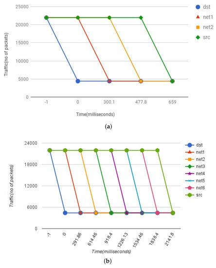
Figure 8.
Mitigation Effect in ISP Setting: Shows the effect of mitigation transferred from destination to the source in real ISP settings with AS-AS Latency and Processing Delays. (a) Two Intermediate Networks; (b) Six Intermediate Networks.
The larger number of Intermediate networks have proportional increase in the mitigation time. Nevertheless, our proposed framework and C-to-C protocol is lightweight with instantaneous effect. It only requires somewhere between 290 to 330 ms to process and forward attack definitions from one network to another in realistic ISP settings.
4.3.2. Mesh and Centralized Approach
In the fully meshed and centralized approach, the controllers are directly connected with each other. This way the attack definitions or flows are pushed from the destination to Intermediate and source networks. We performed a similar experiment as discussed above, but with a mesh of controllers connected with each other or a centralized way of carrying out communication, the effect is very immediate as compared to the linear approach. Figure 9 shows the immediate drop in attack traffic since the controllers are connected directly and the flows are pushed right from the destination or central platform to the individual networks.
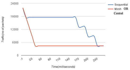
Figure 9.
Linear vs. Mesh or Central: Shows a time based comparison of Policy Propagation delay between linear and mesh approach. Due to direct connection in mesh or central approach the mitigation effect is immediate.
4.4. Performance of Central Control Platform
The main idea of central control platform is to create a trusted authority that verifies the attack definitions received so that intermediate controllers do not have to go through the laborious task of individually verifying and forwarding the attack definitions. The result of this approach is quite similar to the one achieved in the Mesh approach. In this section we evaluate the efficiency and scalability of the central control platform. This includes the effect of payload size, dissemination delays and throughput of the flows and system benchmarks (CPU and memory usage). For the performance evaluations, we used a low end machine with Intel core i3-4010U 1.7 GHZ × 4 CPU with 4.0 GB of RAM as the central controller.
4.4.1. Effect of Payload Size
The performance of our system also depends upon the payload size of an attack definition which mainly consists of malicious IP addresses. We took various payloads and computed the time to verify and process the IP addresses to generate relevant flow table entries. Figure 10 display the effect of the increasing size of payloads . It took on average of 1.8 ms to process (verification of signature and insertion of flow table entry) a payload containing 1000 IP addresses. The processing time increases to 13 ms for payload with 10,000 IP addresses and around 137 ms to process 100,000 IP addresses.
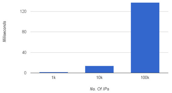
Figure 10.
Effect of payload size on processing delays.
Here we choose 100,000 IP addresses to stress test the computation overhead due to large payload processing on low-end commodity hardware. Unlike routers, the TCAM space in switches are expensive, so it would be more realistic to apply reasonable cap or exchange malicious subnets information instead of IP addresses, in case switches are used as the network component.
4.4.2. Dissemination Delay and Throughput
In order to evaluate the dissemination delays of attack definitions, we generated 100 different payloads with attack definitions and forwarded each payload to 100 connected controllers in three different modes. i.e., Burst mode, with 100 ms delay (the delay added between two different attack definitions), and with 500 ms delay. Figure 11 shows the results. In burst mode i.e., with 0 delay between attack definitions, it took approx. 28 s to dissipate all the flow policy to 100 connected controllers. With a delay of 100 ms, it took approx. 34 s and with a delay of 500 ms it took approximately 50 s.
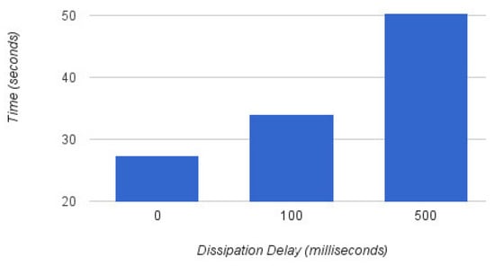
Figure 11.
Central Platform: Load testing at varying delays.
According to the CIDR report [36], the number of ASes in the routing system today are approx. 58,000. Figure 12 shows the growth of ASes count over the years. We measure how the number of ASes effects the time required to process the attack definitions at the central control and the throughput in terms of AS count. For this, we varied the AS count between 5000 to 60,000 (emulating realistic global AS count) and the central control platform forwarded the attack definition with a payload of 100,000 malicious IP addresses, in burst mode, to all the connected ASes. Figure 13 shows the average processing delays for different AS counts. On average it took 21.74 s to process and forward the attack definition to 5000 ASes. An increase in AS count adds a linear increase in the delays and with 60,000 ASes the overall delay was around 252.71 s. These numbers represent delays as per current global AS numbers on average commodity hardware. The performance can significantly improve with high-end computational devices.

Figure 12.
Global AS count in November 2017 [36].
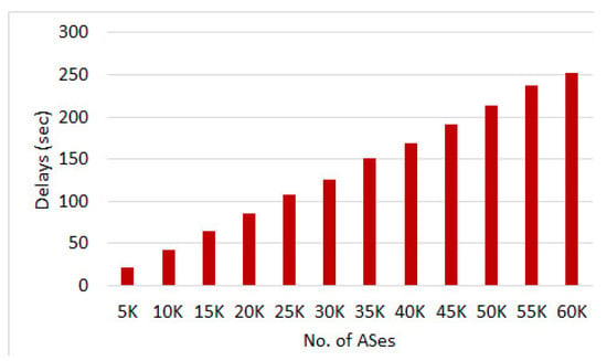
Figure 13.
Payload Dissemination Delays with varying AS Count.
Figure 14 shows the throughput in terms of number of ASes handled per second. The average throughput remained fairly constant throughout the experiment and we were able to forward the attack definitions to 230–237 ASes per second. This is equivalent to disseminating 23 million malicious IP addresses per sec.
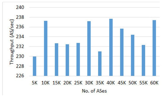
Figure 14.
Average throughput
4.4.3. CPU and Memory Utilization
We also evaluated the CPU and memory utilization while measuring the effect of different AS counts. The average CPU utilization results (see Figure 15) show that the dissemination of attack definition with central control platform is not CPU intensive and it remained between 26% to 35%. Similarly, memory utilization remained constant between 24% to 25% in all the scenarios (see Figure 16).
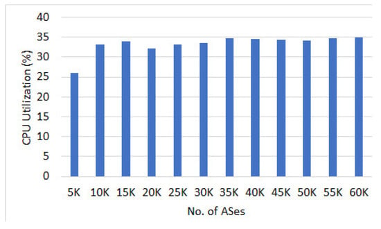
Figure 15.
Avg. CPU usage (%).
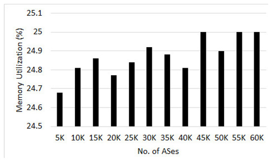
Figure 16.
Avg. memory usage (%).
The evaluation results presented in this section show that the proposed approach is fairly lightweight in mitigating DDoS attacks near the source. The amount of time it takes to completely mitigate the attack all the way from the destination to the source is instantaneous. Our stress tests and micro benchmarks show that the overheads imposed by the additional processing (verification and forwarding of attack definition) are tolerably small on average commodity hardware. The performance can significantly improve with high-end industry scale computational devices.
5. Conclusions
This paper takes an important step by presenting a lightweight, efficient and easy to deploy collaborative DDoS mitigation scheme leveraging SDN. Using the proposed scheme, a SDN controller in any AS can directly communicate with the controllers in the adjacent network via secure C-to-C protocol and inform them about an ongoing attack. This helps in efficient propagation of attack definitions all the way from the victim to the attack sources. We also introduced three different deployment approaches i.e., linear, central and mesh in our testbed and tested the overall efficiency.
Experiments with our prototype implementation show that the effect of mitigation is instantaneously transferred from destination to source. It took around 2.14 s to mitigate the attack in an eight hop linear deployment. Furthermore, it only requires somewhere between 290 to 330 ms to process and forward attack definitions between adjacent networks. The processing of attack definition payload (verification of signature and insertion of flow table entry) is also lightweight even on low end machines with a processing time of around 13 ms for a payload with 10,000 IP addresses. The performance benchmark of central deployment approach show reasonable CPU (35%) and memory (25%) utilization on average commodity hardware. The results also show that it only took 21 s to disseminate attack definition to 5000 AS. Of course, with high-end expensive servers the dissemination time can be significantly reduced.
Author Contributions
Sufian Hameed proposed the research problem and solution architecture for the Collaborative DDoS mitigation using SDN paradigm. He also drafted the manuscript. Hassan Ahmed Khan helped in prototype implementation and evaluations of the proposed solution.
References
- Zargar, S.T.; Joshi, J.; Tipper, D. A survey of defense mechanisms against distributed denial of service (DDoS) flooding attacks. Commun. Surv. Tutor. IEEE 2013, 15, 2046–2069. [Google Scholar] [CrossRef]
- Anagnostopoulos, M.; Kambourakis, G.; Kopanos, P.; Louloudakis, G.; Gritzalis, S. DNS amplification attack revisited. Comput. Secur. 2013, 39, 475–485. [Google Scholar] [CrossRef]
- Santanna, J.J.; van Rijswijk-Deij, R.; Hofstede, R.; Sperotto, A.; Wierbosch, M.; Granville, L.Z.; Pras, A. Booters — An analysis of DDoS-as-a-service attacks. In Proceedings of the 2015 IFIP/IEEE International Symposium on Integrated Network Management (IM), Ottawa, ON, Canada, 11–15 May 2015; pp. 243–251. [Google Scholar]
- DYN Cyberattack. Available online: www.theguardian.com/technology/2016/oct/26/ddos-attack-dyn-mirai-botnet (accessed on 25 November 2017).
- Kolias, C.; Kambourakis, G.; Stavrou, A.; Voas, J. DDoS in the IoT: Mirai and Other Botnets. Computer 2017, 50, 80–84. [Google Scholar] [CrossRef]
- Pras, A.; Santanna, J.J.; Steinberger, J.; Sperotto, A. DDoS 3.0-How terrorists bring down the Internet. In Proceedings of the International GI/ITG Conference on Measurement, Modelling, and Evaluation of Computing Systems and Dependability and Fault Tolerance, Münster, Germany, 4–6 April 2016; Springer: Cham, Switzerland, 2016; pp. 1–4. [Google Scholar]
- Yan, Q.; Yu, F.R. Distributed denial of service attacks in software-defined networking with cloud computing. IEEE Commun. Mag. 2015, 53, 52–59. [Google Scholar] [CrossRef]
- Kalkan, K.; Gur, G.; Alagoz, F. Defense Mechanisms against DDoS Attacks in SDN Environment. IEEE Commun. Mag. 2017, 55, 175–179. [Google Scholar] [CrossRef]
- D’Cruze, H.; Wang, P.; Sbeit, R.O.; Ray, A. A Software-Defined Networking (SDN) Approach to Mitigating DDoS Attacks. In Information Technology-New Generations; Springer: Cham, Switzerland, 2018; pp. 141–145. [Google Scholar]
- Giotis, K.; Apostolaki, M.; Maglaris, V. A reputation-based collaborative schema for the mitigation of distributed attacks in SDN domains. In Proceedings of the IEEE/IFIP Network Operations and Management Symposium, Istanbul, Turkey, 25–29 April 2016. [Google Scholar]
- Yang, X.; Wetherall, D.; Anderson, T. TVA: a DoS-limiting network architecture. IEEE Trans. Netw. 2008, 16, 1267–1280. [Google Scholar] [CrossRef]
- Yang, X.; Wetherall, D.; Anderson, T. A DoS-limiting network architecture. In ACM SIGCOMM Computer Communication Review; ACM: New York, NY, USA, 2005. [Google Scholar]
- Ioannidis, J.; Bellovin, S.M. Implementing Pushback: Router-Based Defense Against DDoS Attacks. In Proceedings of the Network and Distributed System Security Symposium (NDSS), San Diego, CA, USA, 6–8 February 2002. [Google Scholar]
- Hameed, S.; Khan, H.A. Leveraging SDN for collaborative DDoS mitigation. In Proceedings of the IEEE International Conference on Networked Systems (NetSys), Goettingen, Germany, 13–16 March 2017. [Google Scholar]
- François, J.; Dolberg, L.; Festor, O.; Engel, T. Network security through software defined networking: A survey. In Proceedings of the Conference on Principles, Systems and Applications of IP Telecommunications, Chicago, IL, USA, 1–2 October 2014; ACM: New York, NY, USA, 2014; p. 6. [Google Scholar]
- Braga, R.; Mota, E.; Passito, A. Lightweight DDoS flooding attack detection using NOX/OpenFlow. In Proceedings of the 35th IEEE Conference on Local Computer Networks (LCN), Denver, CO, USA, 10–14 October 2010. [Google Scholar]
- Lim, S.; Ha, J.; Kim, H.; Kim, Y.; Yang, S. A SDN-oriented DDoS blocking scheme for botnet-based attacks. In Proceedings of the Sixth International Conference on Ubiquitous and Future Networks (ICUFN), Shanghai, China, 8–11 July 2014. [Google Scholar]
- Giotis, K.; Androulidakis, G.; Maglaris, V. Leveraging SDN for Efficient Anomaly Detection and Mitigation on Legacy Networks. In Proceedings of the Third European Workshop on Software Defined Networks, Budapest, Hungary, 1–3 September 2014. [Google Scholar]
- Jeong, J.; Seo, J.; Cho, G.; Kim, H.; Park, J.S. A Framework for Security Services Based on Software-Defined Networking. In Proceedings of the 2015 IEEE 29th International Conference on Advanced Information Networking and Applications Workshops (WAINA), Guwangiu, Korea, 24–27 March 2015. [Google Scholar]
- Fayaz, S.K.; Tobioka, Y.; Sekar, V.; Bailey, M. Bohatei: Flexible and Elastic DDoS Defense. In Proceedings of the USENIX Security Symposium, Austin, TX, USA, 10–12 August 2015; pp. 817–832. [Google Scholar]
- Chen, C.C.; Chen, Y.R.; Lu, W.C.; Tsai, S.C.; Yang, M.C. Detecting amplification attacks with Software Defined Networking. In Proceedings of the 2017 IEEE Conference on Dependable and Secure Computing, Taipei, Taiwan, 7–10 August 2017; pp. 195–201. [Google Scholar]
- Aizuddin, A.A.; Atan, M.; Norulazmi, M.; Noor, M.M.; Akimi, S.; Abidin, Z. DNS amplification attack detection and mitigation via sFlow with security-centric SDN. In Proceedings of the 11th International Conference on Ubiquitous Information Management and Communication, Beppu, Japan, 5–7 January; ACM: New York, NY, USA, 2017; p. 3. [Google Scholar]
- Liu, J.; Lai, Y.; Zhang, S. FL-GUARD: A Detection and Defense System for DDoS Attack in SDN. In Proceedings of the International Conference on Cryptography, Security and Privacy, Wuhan, China, 17–19 March 2017; ACM: New York, NY, USA, 2017; pp. 107–111. [Google Scholar]
- Belyaev, M.; Gaivoronski, S. Towards load balancing in SDN-networks during DDoS-attacks. In Proceedings of the 2014 International Science and Technology Conference (Modern Networking Technologies) (MoNeTeC), Moscow, Russia, 27–29 October 2014. [Google Scholar]
- Dao, N.N.; Park, J.; Park, M.; Cho, S. A feasible method to combat against DDoS attack in SDN network. In Proceedings of the International Conference on Information Networking (ICOIN), Siem Reap, Cambodia, 12–14 January 2015. [Google Scholar]
- Rebecchi, F.; Boite, J.; Nardin, P.A.; Bouet, M.; Conan, V. Traffic monitoring and DDoS detection using stateful SDN. In Proceedings of the 2017 IEEE Conference on Network Softwarization (NetSoft), Bologna, Italy, 3–7 July 2017; IEEE: Berlin, Germany, 2017; pp. 1–2. [Google Scholar]
- François, J.; Aib, I.; Boutaba, R. FireCol: A collaborative protection network for the detection of flooding DDoS attacks. IEEE/ACM Trans. Netw. (TON) 2012, 20, 1828–1841. [Google Scholar] [CrossRef]
- Rashidi, B.; Fung, C. CoFence: A collaborative DDOS defence using network function virtualization. In Proceedings of the 12th International Conference on Network and Service Management (CNSM), Montreal, QC, Canada, 31 October–4 November 2016; IEEE: Berlin, Germany, 2016; pp. 160–166. [Google Scholar]
- Chen, X.F.; Yu, S.Z. CIPA: A collaborative intrusion prevention architecture for programmable network and SDN. Comput. Secur. 2016, 58, 1–19. [Google Scholar] [CrossRef]
- Hameed, S.; Ali, U. Efficacy of Live DDoS Detection with Hadoop. In Proceedings of the IEEE/IFIP Network Operations and Management Symposium (NOMS), Istanbul, Turkey, 25–29 April 2016. [Google Scholar]
- POX Controller. Available online: www.github.com/noxrepo/pox (accessed on 15 September 2017).
- Mininet. Available online: www.mininet.org/ (accessed on 15 September 2017).
- Scapy. Available online: www.secdev.org/projects/scapy/ (accessed on 11 August 2017).
- Sender Policy Framework. Available online: http://www.openspf.org/ (accessed on 25 November 2017).
- Autonomous System Path Lengths. Available online: https://labs.ripe.net/Members/mirjam/update-on-as-path-lengths-over-time (accessed on 15 December 2017).
- Number of ASes in Routing System. Available online: http://www.cidr-report.org/as2.0/ (accessed on 15 December 2017).
© 2018 by the authors. Licensee MDPI, Basel, Switzerland. This article is an open access article distributed under the terms and conditions of the Creative Commons Attribution (CC BY) license (http://creativecommons.org/licenses/by/4.0/).