1. Introduction
Environmental monitoring plays an important role in geography detection, disaster prediction and agriculture. In recent years, researchers have focused on the monitoring system to improve the quality of our daily life, and there have been some literatures in relation to this.
In Reference [
1], the authors proposed a fiber-optic low-coherent interferometry sensor to measure the ground settlement (GS). The optical interferometry was used to illustrate liquid level changes, reflecting where the GS happened. Thus, the GS information was calculated based on the optical interferometry. To detect pollutants in real-time, the authors of Reference [
2] proposed environmental lab-on-a-chip monitoring and focused on future perspectives to overcome monitoring challenges using printing technologies. Considering flood risks in Thailand, the authors studied the livelihood vulnerability in Northeast Thailand [
3]. Inefficient monitoring of land and house elevations was shown to be the major factor leading to flood risks. For disaster environments such as flooding, both monitoring data redundancy and limited network transmission capacity were considered together to improve disaster resistance [
4]. For agriculture, the groundwater subsidy had significant influence on cropping systems. Therefore, leaching monitoring started in Taiwan 10 years ago, but real-time monitoring was impossible. The authors of Reference [
5] developed a data transmission path, named ICT (Information and Communication Technology), which is used to improve the efficiency of data transmission from the field to the databases located in labs. For fluvial monitoring, the authors proposed a microfluidic phosphate sensor to reduce temperature effects [
6]. The sensor realizes greater power economy, a mean power consumption of 1.8 W. During field testing, the sensor was able to continuously work for 60 days in a chalk stream, illustrating complex relations between phosphate concentration and flow rates.
For the present university laboratory management, it is necessary to deploy an environmental monitoring system. Manual inspection [
7] can ensure laboratory safety, but this wastes power and time. Compared to manual inspection, a traditional wiring experiment alarm device, such as RS-232, can save more resources [
8]. The drawback is that this method is difficult to be generalized due to the restriction of conditions (e.g., wiring environment and transmission distance). Another method, the ZigBee wireless data transmission network [
9], is influenced by some conditions such as transmission distance, and circuit-switched data transmission may lead to short message congestion and loss. In addition to this, there is other related research [
10], in which the idea of a monitoring system with GPRS communication is proposed but without the realization process. The aforementioned studies do not consider the combination of sensor technology, wireless communications and other important technologies [
11,
12]. Moreover, some functions, such as fire prevention and automatic SMS alarm, are not realized at the same time [
13,
14].
Since GPRS communication using packet switching technology is able to realize reliable remote wireless communication, this paper proposes an intelligent monitoring system to realize environmental detection in university laboratories. The main purpose of this system is to monitor the laboratory environment data in time and improve the laboratory inspection efficiency. The system consists of a single chip microcomputer, which is the core of this system, sensor function module and GPRS wireless communication, realizing data monitoring and short message warning. Therefore, three features, including front-end data acquisition, data wireless transmission and security alarm, are achieved by the proposed system. The system uses development tools including Keil-uVision4 [
15], Protel99SE, Proteus and a firing machine. The system is programmed using JAVA [
16], achieving data detection and remote control using a mobile terminal APP. It combines wireless communication protocol, system control instruction and a sensor manual to design the module function of our proposed system. The proposed system, with characteristics including user-friendly control, high performance and reliable operation, is an application in Internet of things. Compared to a traditional environmental monitoring mode, our system is more suitable for environmental monitoring and extensive usage. For instance, it can be used as a subsystem [
17] which is able to connect the public network through the specific interface. The platform then analyzes and processes the collected information. This process can be controlled by different terminals. In addition, our system can also speed up the information construction of colleges and universities. The real experiments show that front-end data acquisition is effective, data transmission is reliable, and the alarm message is received in time.
The main contributions of this paper are summarized below.
The proposed system consists of a single chip microcomputer, GPRS wireless communication and a sensor function module realizing data monitoring and short message warning. Therefore, three features, including front-end data acquisition, wireless communication and security alarm, are achieved by the proposed system.
The system mainly uses Keil-uVision4, Proteus, Protel99SE and a firing machine as the development tools to design the module function of system.
The real experiments show that the function of front-end data acquisition is effective, data transmission is reliable, and the alarm message is received in time.
The rest of the paper is organized as follows. In
Section 2, the system architecture, including the data acquisition module and control and the communication module, is proposed.
Section 3 illustrates the system software design idea. In
Section 4, the proposed system is tested under real conditions and an analysis of some debugging results is described. Finally, conclusions are shown in
Section 5.
2. System Design and Implementation
In this section, we describe the data acquisition module and the control and communication module of our proposed system.
2.1. System Function Introduction
Based on the current situation of university laboratory management and Internet of things technology, we propose a monitoring system that integrates sensor technology, wireless communications and other important technologies. This proposed system achieves many functions, such as monitoring indoor light off, temperature and humidity detection, anti-theft, and fire prevention. The details of the system functions are as follows:
- (1)
Special voice prompts for the current function that the proposed system will achieve and the operation that the proposed system will complete.
- (2)
Testing the concentration of combustible gas in the laboratory and investigating fire risk 24 h a day.
- (3)
Achieving the multiple-point measurement of humidity and temperature, and obtaining feedback from the measured temperature and humidity accurately.
- (4)
Monitoring whether there are illegal persons entering the laboratory during the unused period.
- (5)
Monitoring the light intensity of the laboratory in the unused period and judging the situation of lighting in the laboratory.
- (6)
Displaying the monitoring data in mobile terminals by which administrators can realize remote monitoring.
- (7)
Achieving wireless data transmission in time. When a disaster occurs, the system starts a buzzer alarm and a remote dial-up alarm to inform administrators with the SMS signal in time.
2.2. System Model Design and Function Realization
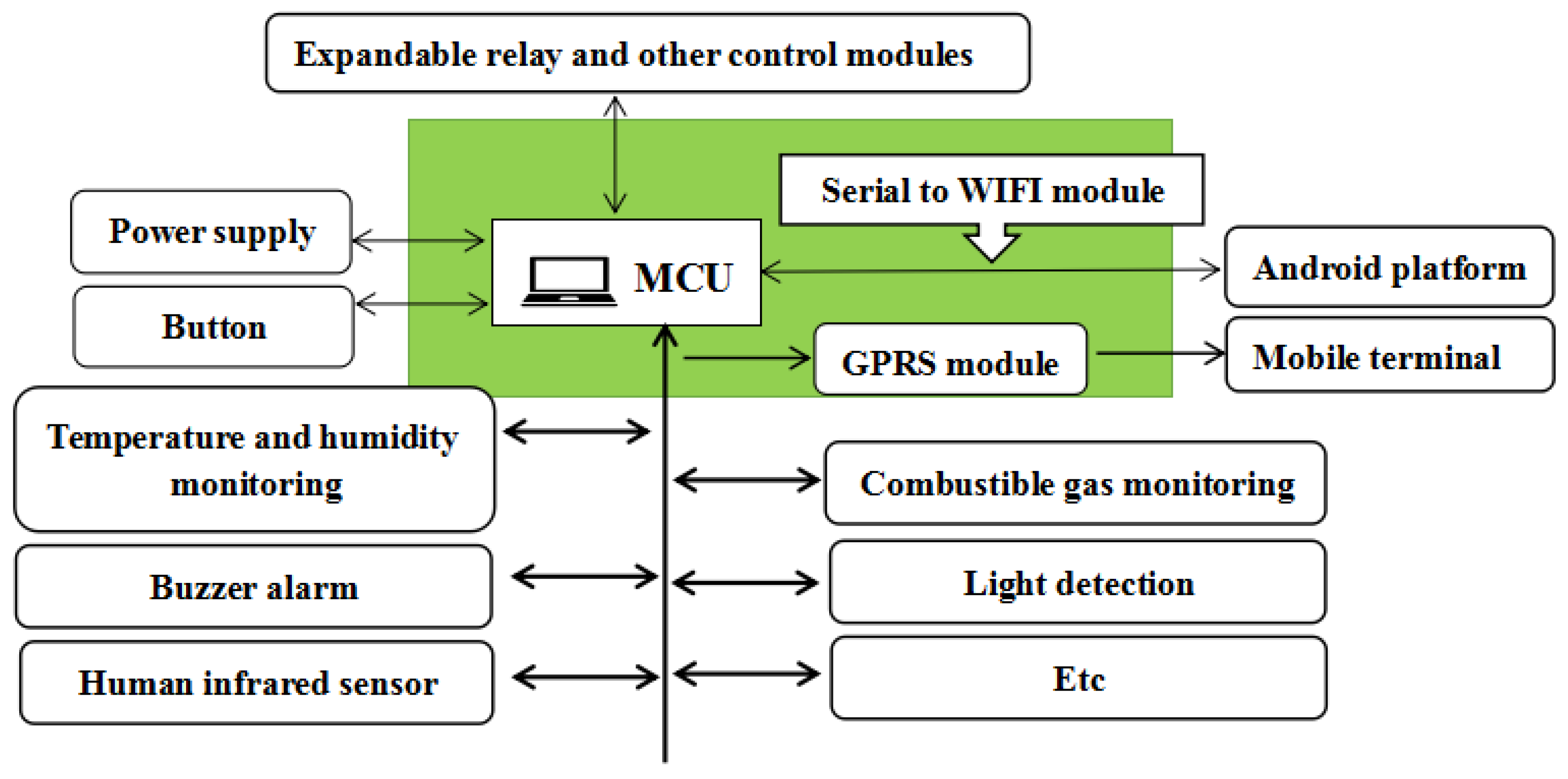
To achieve the aforementioned functions, the proposed system consists of a GPRS module, STC12C5A60S2 (STC, Shenzhen, China) and sensor detection modules. In our system, the software Protel99SE (Altium, Sydney, Austrilia) is used to drive each part of the system’s hardware circuit and generate the system function development board. The overview of our system architecture is illustrated in
Figure 1.
Each sensor module has a responsibility to collect the laboratory data and return the data to the administrator’s mobile terminal by message. Moreover, the system can analyze dangerous situations (e.g., fire protection and security) during the process of collecting data and realize the buzzer alarm and the SMS alarm automatically. Furthermore, the system development board takes SMS command control, automatic data acquisition and data control into account. The serial port is integrated to the WIFI module and the system is programmed by the JAVA program, achieving data detection and remote control using mobile terminal APP.
With the development of large scale laboratories, the proposed system can be used independently. It can also be used as a subsystem which is able to connect the public network through the specific interface. Then, the platform analyzes and processes the collected information. This process can be controlled by different terminals.
2.3. Each Module of Proposed System
2.3.1. Control and Communication Module
The system uses a single chip microcomputer STC12C5A60S2 as the control core. It also contains a GPRS module (SIM900A, SIMCom, Shanghai, China) to complete the communication with the mobile terminal realizing real-time monitoring.
The GPRS module is used to initialize a circuit and create a channel into the listening state when the serial port is connected to MCU. After collected data is written in the buffer, this module sends the data to the designated mobile terminals. This system chooses SIM900A module embedded TCP/IP protocol. For users, expanding TCP/IP AT commands is convenient to transmit data. Thus, we use AT command to control GPRS module. After querying the manual of the corresponding command, we know AT command consists of data format, initialization and waiting command.
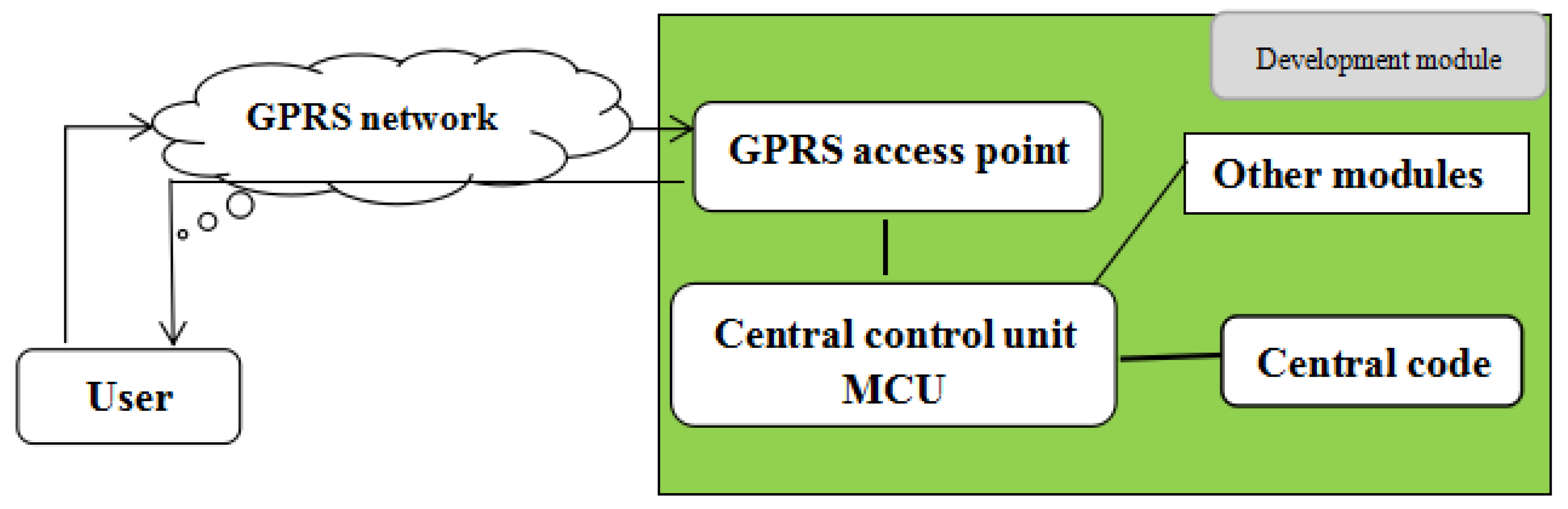
Based on STC12C5A60S2 and GPRS network, the remote communication framework of the system builds a communication mode. As shown in
Figure 2, a user sends query request, in the form of short message using mobile phone, to the center control unit. Then, MCU detects the user’s request from the GRPS network access point.
2.3.2. Data Acquisition Module
The system acquisition module uses digital sensors without external A/D conversion so that it is convenient to design. To guarantee the launch order of the GPRS module, the development board adopts power DC12V/2A. Meanwhile, 3.3 V and 5 V voltage chips are embedded. This can ensure that other data gathering modules work normally. The selection process of data acquisition sensor modules is shown in
Table 1.
DHT11 (temperature and humidity collection module): Application of this composite module can monitor indoor humidity and temperature and provide the test results in the form of a digital signal. This module has better anti-interference ability and single-wire serial interface, which is helpful to system integration. Considering the impact of laboratory space, the appropriate pull-up resistor is selected based on the actual size of the laboratory.
GY-30 (light intensity acquisition module): Through the application of the module, the sensor can measure a wide range of brightness and cut off the indoor light. Its internal 16-bit A/D converter can directly output a digital signal, independent of external A/D conversion unit and ambient light. The light spectrum is similar to that of the human eye. Thus, the impact on the infrared, which is small, does not influence the work of other modules.
MQ-9 (fire monitoring module): Application of this detection device can monitor methane, carbon monoxide and other flammable gas. The module has a signal output, 0–5 V voltage. The larger the concentration is, the higher the voltage.
HC-SR501 (human body infrared sensor module): Using the infrared control technology, the HC-SR501 can achieve automatic sensing. It is set in the induction block time, in which the sensor cannot receive any induction signals. This module can be applied to the interval detection to inhibit the load switching process caused by a variety of interference.
3. System Software Design
The system uses several development tools including Proteus (LCE, London, England), Protel99SE (Altium, Sydney, Austrilia), Keil-uVision4 (ARM, London, England) and a firing machine. It combines wireless communication protocol, system control instruction and a sensor manual to design the module function of our proposed system.
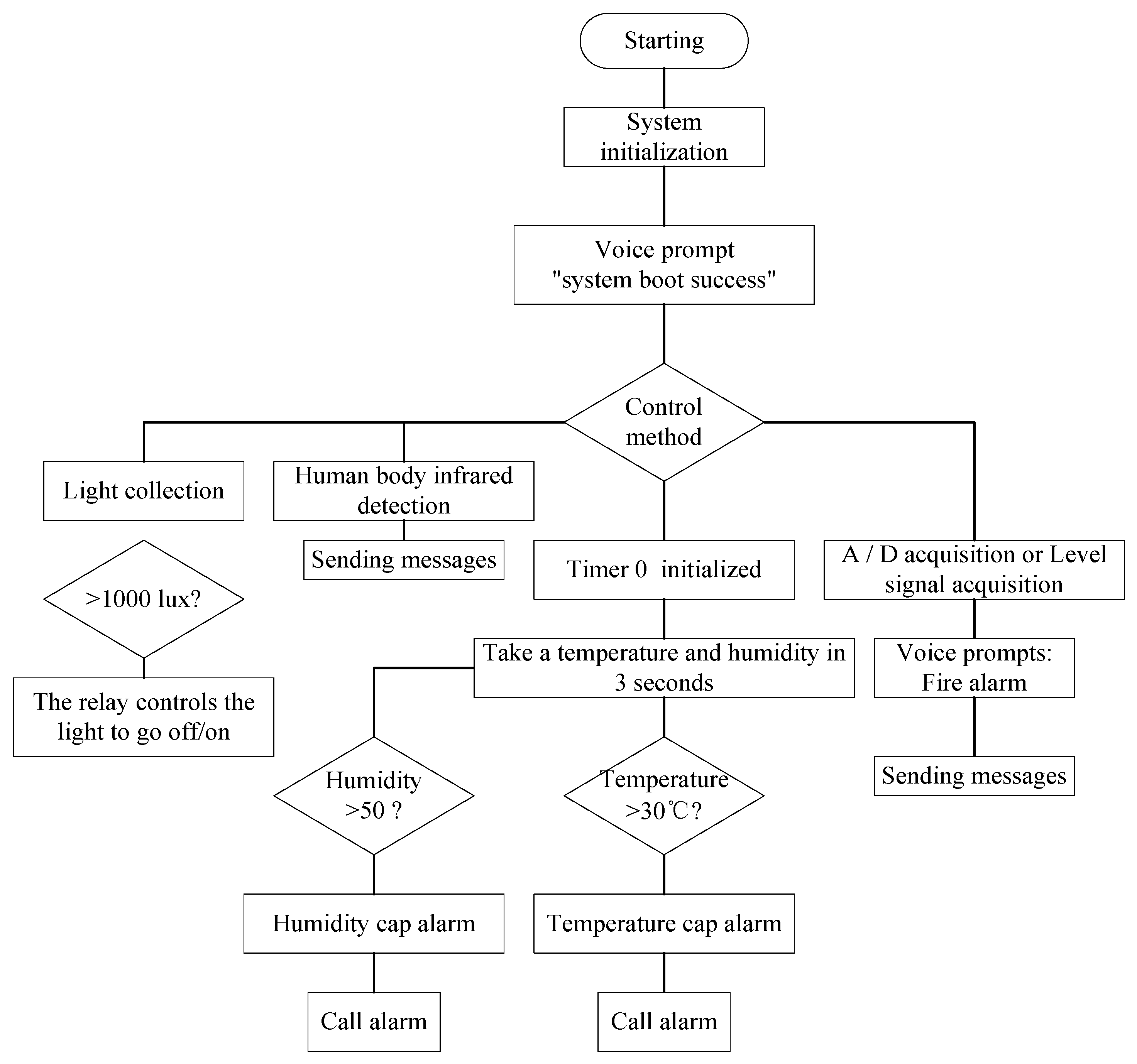
We build the project under Keil-uVision4’s C language development environment and design the source code of the module function. We use Keil-uVision4 and Proteus to realize the module simulation in process of the hardware circuit design. Protel99SE, a design tool, is used to finish hardware circuit schematic and PCB board. At last, we confirm that the whole source code debugging is correct, and run the program under the condition that partial hardware circuit simulation is completed. The flow chart of the system program is shown in
Figure 3.
As shown in
Figure 3, the first step is the system initialization when the program is starting. After that, there will be the voice prompt “system boot success” which means the system initialization is successful. Then, there are four branches for different monitoring objects including light monitoring, body infrared detection, temperature and humidity detection, and the fire alarm. For light monitoring, based on light collection, if the collected data are higher than 1000 lux, the relay causes the light to go off. For the body infrared detection, when a body is detected, a message is sent. For temperature and humidity detection, we set up the threshold of humidity and temperature. When the detected data of humidity and temperature exceeds the predefined threshold, it will call an alarm. For the fire alarm, voice prompts such as “fire alarm” are launched when the acquired signal is higher than the predefined level, and the corresponding messages are sent.
4. Real Experiments
We discuss the real experiment results of our proposed system and how they can be interpreted in perspective of previous studies and working hypotheses.
4.1. Program Debugging Method
Using the Keil-uVision4, the proposed system writes and debugs the designed program. When debugging occurs in this environment, we set program break-points at first. Break-points are activated after starting up debugging. Break-points are set to variable, conditional expression or memory access. Debugging functions and debugger commands are executed after break-points are triggered. Thus, we can easily browse the property box with the break-point settings and locate the source program.
4.2. Hardware Testing Method
Testing the power design was the first step in meeting the hardware testing requirements of our proposed system. Then, with power supply for the development board, we tested whether the power could successfully start the GPRS module. Furthermore, we tested whether the various sensors were able to collect environmental data and return such data to the display terminal. After the normal data collection test, data transmission of laboratory humidity and temperature or indoor light intensity was tested, as well as danger tips which are sent out under abnormal conditions (e.g., high requirements about temperature and humidity). In addition to this, we needed to test whether there was a message responding to a dangerous situation when a person walked around in the induction range of the human body infrared module, whether the buzzer alarm worked normally and whether the SMS alarm function was achieved under the condition of simulated fire. Finally, we integrated the proposed system and selected several laboratories for practical testing. In a word, under the operation of the system, we monitored the stability of all modules, analyzed the logical features of combined modules, and confirmed that the system can execute effective environmental monitoring and alarms.
4.3. Testing
Using a DC12 V (5.5 × 2.1) power line to supply power to the development board, the system realized the voice reminder “system boot success”. Other modules were quickly activated with electricity, while the GPRS module had approximately one minute’s start time.
In a 10 × 8 m
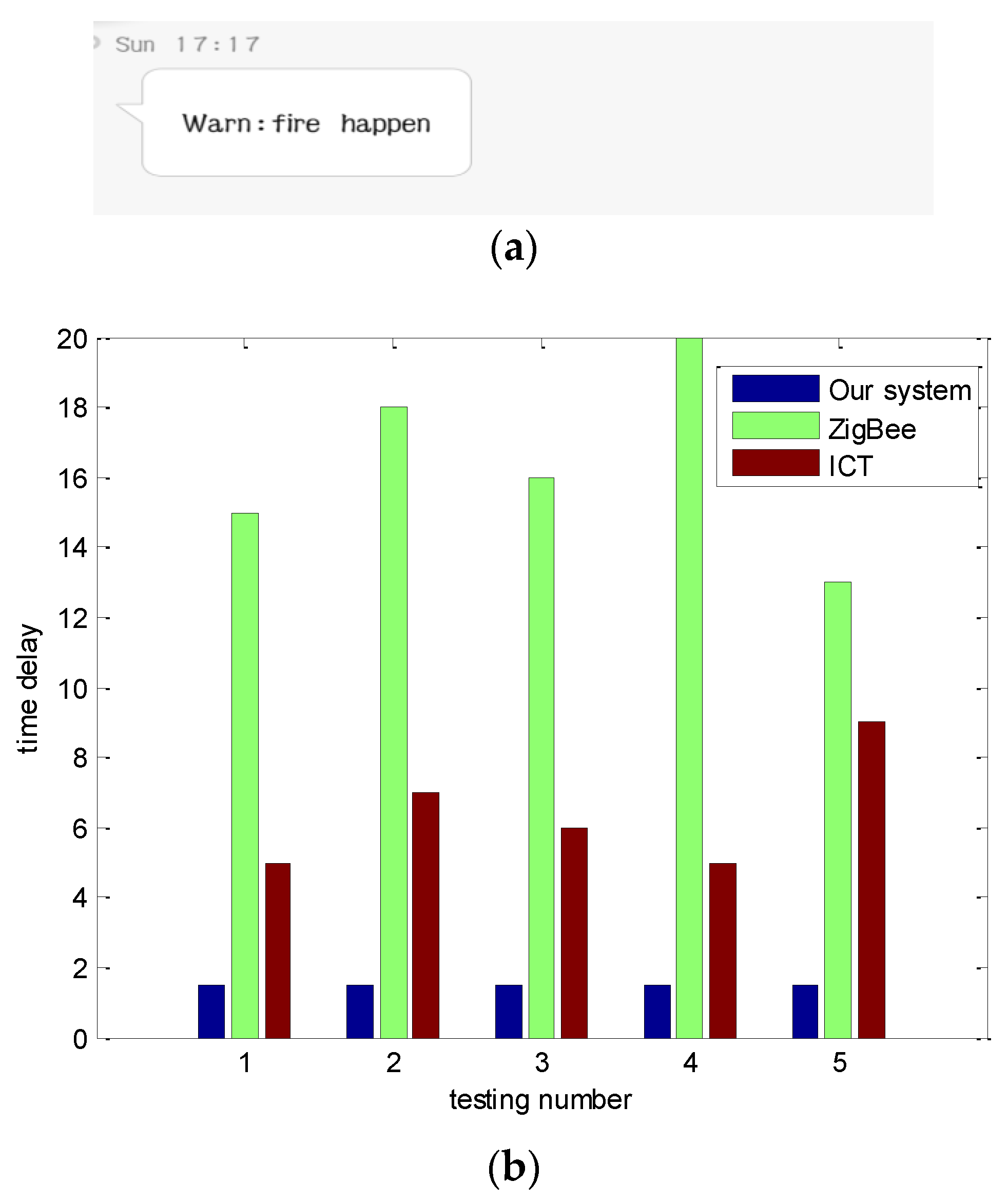
2 indoor experiment, we used the liquefied gas in the lighter to simulate real fire. When the concentration reached a threshold set by the module, the buzzer launched the alarm automatically, and the system showed the voice reminder “fire alarm” and sent an alarm message. Our proposed system can display the message in mobile telephone, while ICT [
5] and ZigBee [
9] systems are not able to do this. A screenshot of the fire alarm message is shown in
Figure 4a.
Figure 4b shows that our system experiences less time delay than the ZigBee and ICT systems because wireless communications, embedded technology and the sensor technology are integrated in our system. As shown in
Figure 4b, we tested the system five times. In each test, our system was able to launch the fire alarm within 2 s, while the ZigBee and ICT systems have a longer time delay before they launch the fire alarm, and unstable time delay in each test.
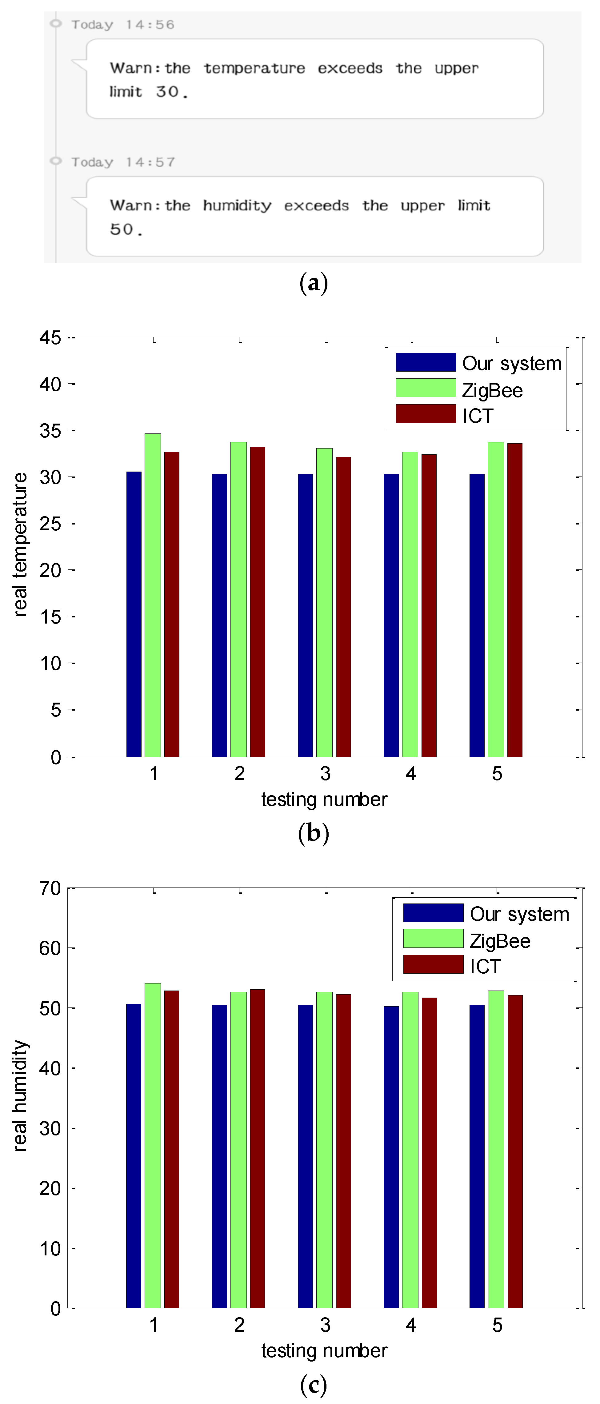
Figure 5 shows the application test of the system, related to the data collection of humidity and temperature modules. The system collects humidity and temperature every 3 s. With humid and hot towels (simulating a special case) near DHT11, after the temperature is higher than 30, our proposed system broadcasts the “temperature limit alarm” and alerts the lab administrator by calling default phone. Similarly, when the humidity is higher than 50, our proposed system broadcasts “humidity alarm”, and alerts the lab administrator by calling default phone. When the humidity and temperature reach the upper limits (Humidity 50, Temperature 30) an alarm screenshot of our system is shown in
Figure 5a, while the ZigBee and ICT systems do not have this ability. Furthermore, our system is more sensitive than the ZigBee and ICT systems. As shown in
Figure 5b, we tested the system five times. In each test, our system was able to launch the temperature alarm when the real temperature exceeded 30, while the ZigBee and ICT systems do not launch the temperature alarm until the real temperature exceeds 32.7. In a similar way,
Figure 5c shows our system is able to launch the humidity alarm when the real humidity exceeds 50, while ZigBee and ICT systems do not launch the humidity alarm until the real humidity exceeds 53.6. The reason is that the data transmission in ZigBee and ICT systems is influenced by conditions such as transmission distance leading to message delay.
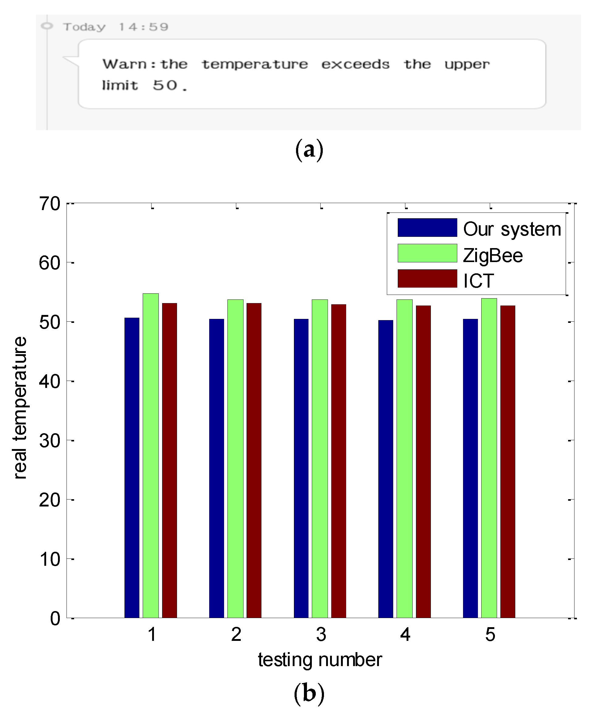
By modifying the corresponding alarm threshold, the upper limit of temperature was changed in the program. To verify the other case, we set the upper limit of the temperature to 50. After environment temperature exceeded the upper limits, the screenshot of the alarm message in our system is shown in
Figure 6a. As shown in
Figure 6b, in each test, our system was able to launch the temperature alarm when the real temperature exceeded 50, while the ZigBee and ICT systems do not launch the temperature alarm until the real temperature exceeds 53.3. The reason is that the data transmission is influenced by transmission distance, leading to transmission delay in the ZigBee and ICT systems.
4.4. Debug Analysis
The control system works based on the information transmission, which mainly depends on the device control information and module acquisition of the physical parameters. This characteristic determines that the transmission rate requirements for various signals are generally low, while the reliability requirements of information transmission are relatively high. Since transmission data denotes the current status of laboratory equipment and control information, even small errors may lead to large malfunctions, causing other equipment to work abnormally or even become damaged. Therefore, the system should guarantee the timeliness and reliability of the transmission.
5. Conclusions
This paper proposes a wireless environment monitoring system for laboratories, consisting of a single chip microcomputer, a sensor function module and GPRS wireless communication. The system integrates wireless communications, embedded technology, sensor technology and other important technologies. Therefore, our system can monitor laboratory environment data in time and improve the efficiency of laboratory inspection. Specifically, the proposed system achieves three features, including front-end data acquisition, data wireless transmission and security alarm. Real tests have proven that the proposed system achieves an effective detection of fire monitoring, temperature and humidity, and other functions. The proposed system, with characteristics that include user-friendly control, high performance and reliable operation, is an application in Internet of things. It can not only work independently, but also can be extended to realize other functions based on actual requirements and treated as a subsystem to access the public network through the specific interface. In addition to this, our system can speed up the information construction of colleges and universities.

