
Experimental and Numerical Modeling of Bending Characteristics of Fir and Black Pine Wood from Different Forest Regions in Türkiye
 , ,
, , 
Abstract
1. Introduction
2. Materials and Methods
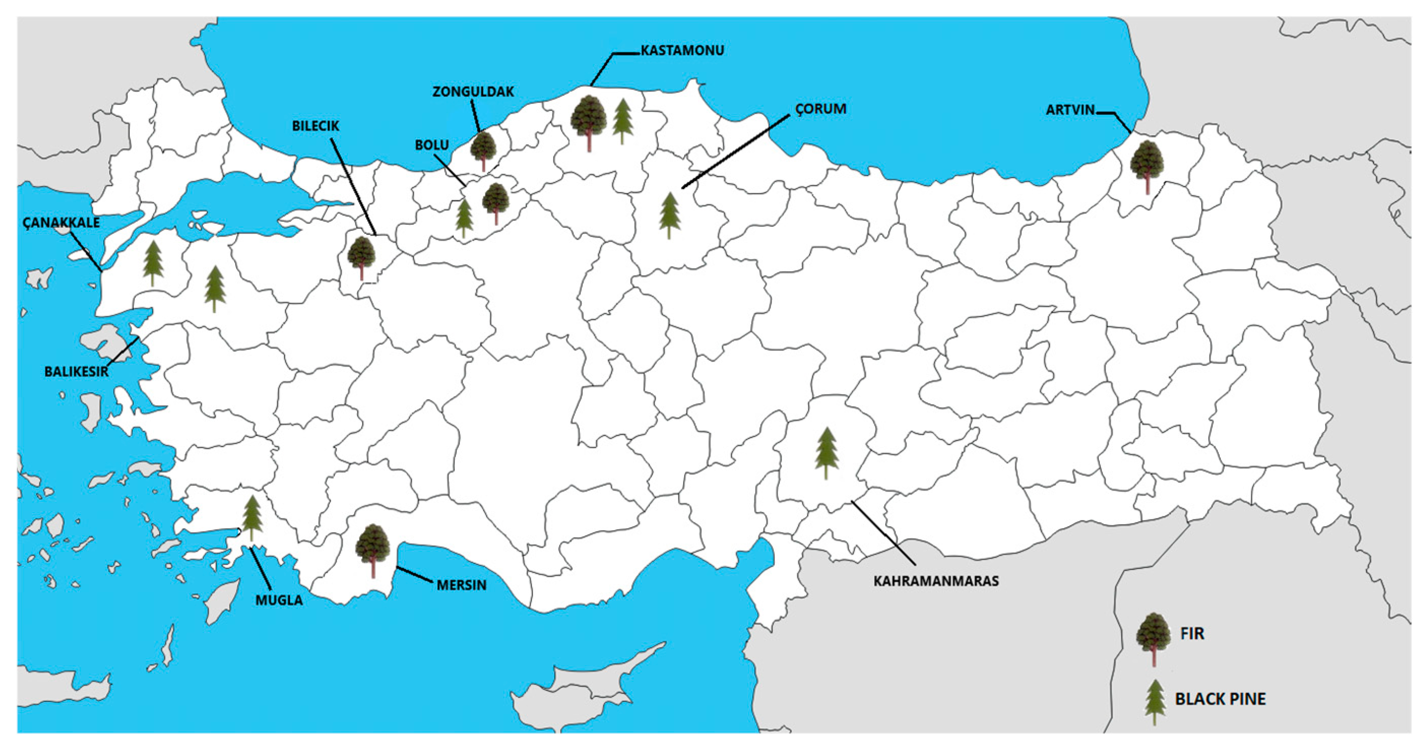
2.1. Materials
2.2. Methods
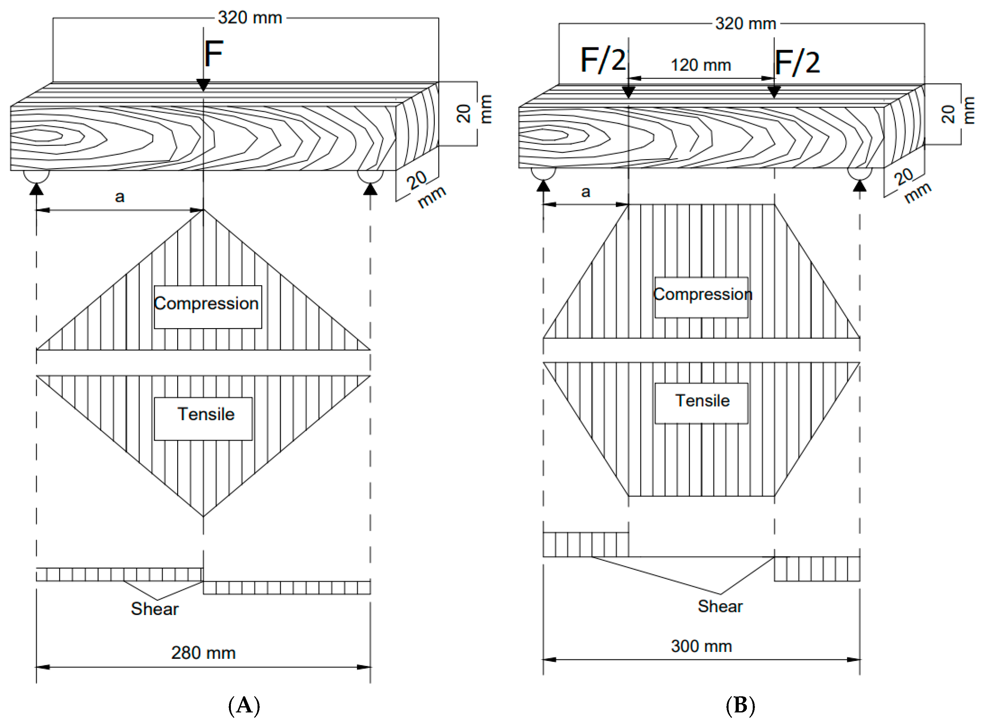
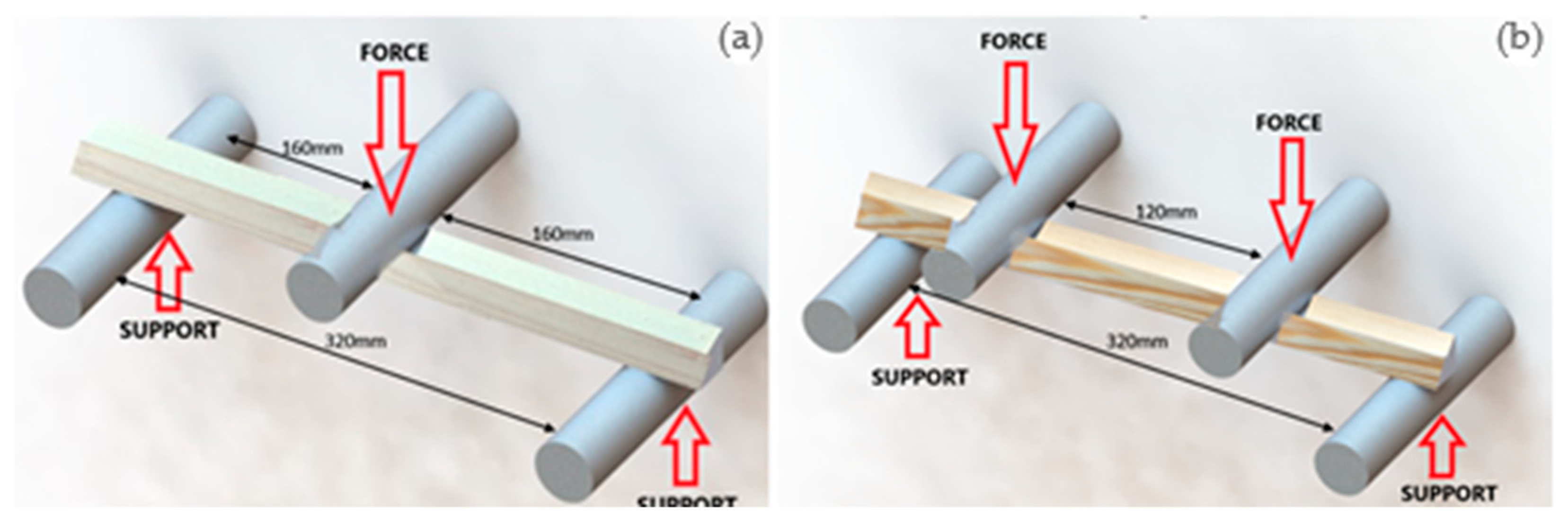
2.2.1. Three-Point Bending
2.2.2. Four-Point Bending
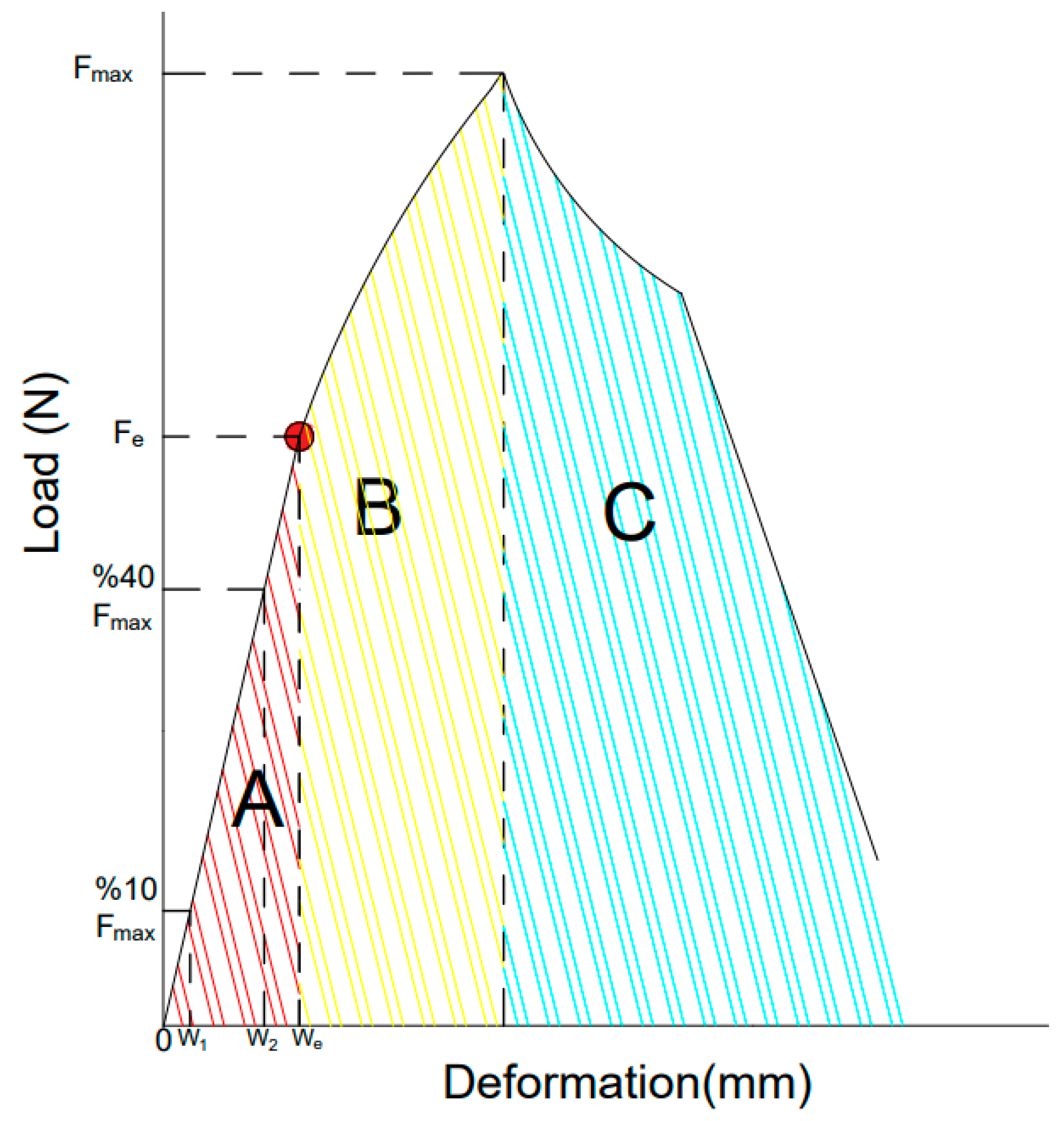
2.2.3. Determination of Other Bending Characteristics
2.2.4. Numerical Modeling
2.2.5. Statistical Analysis
3. Results and Discussion
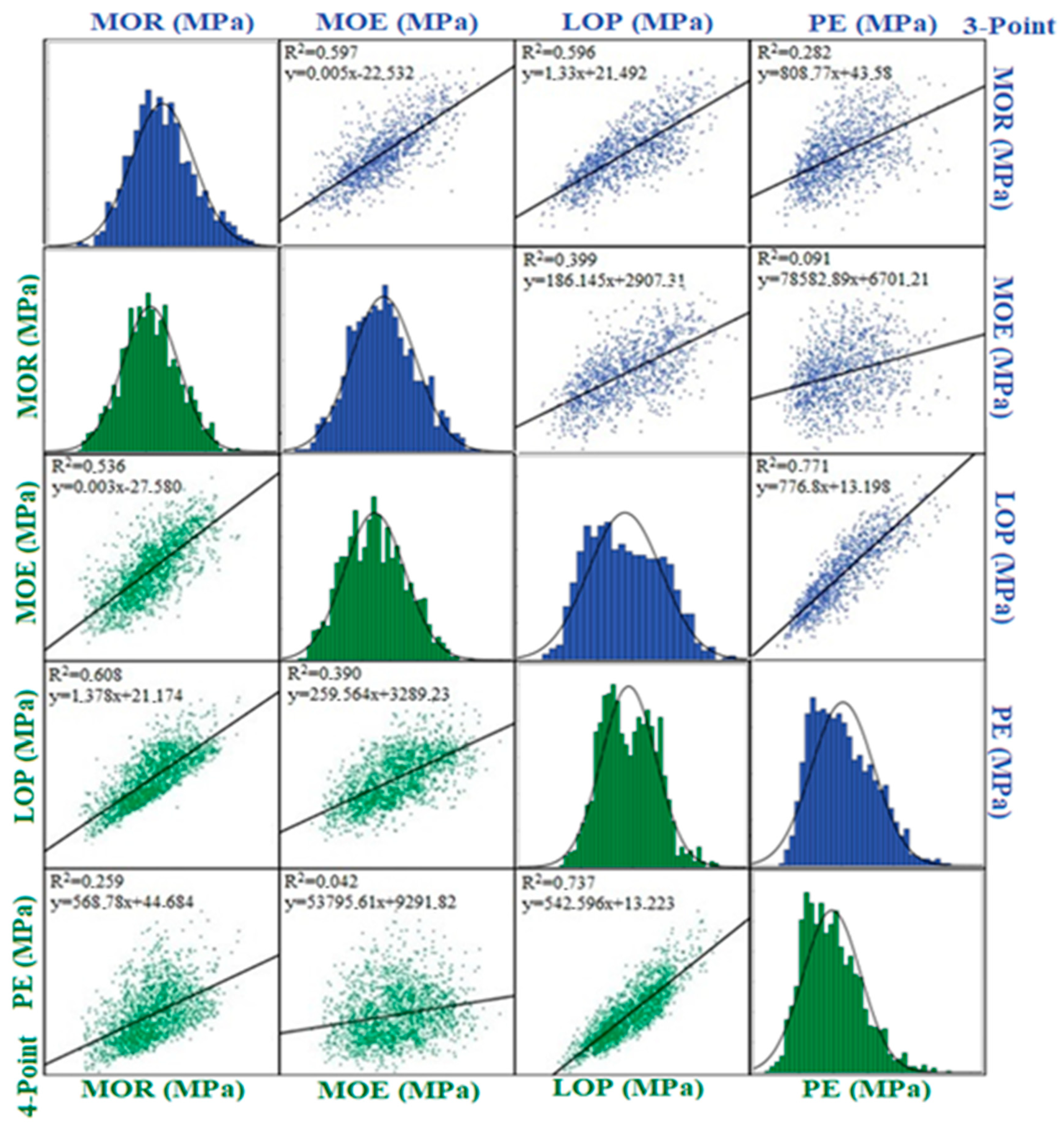
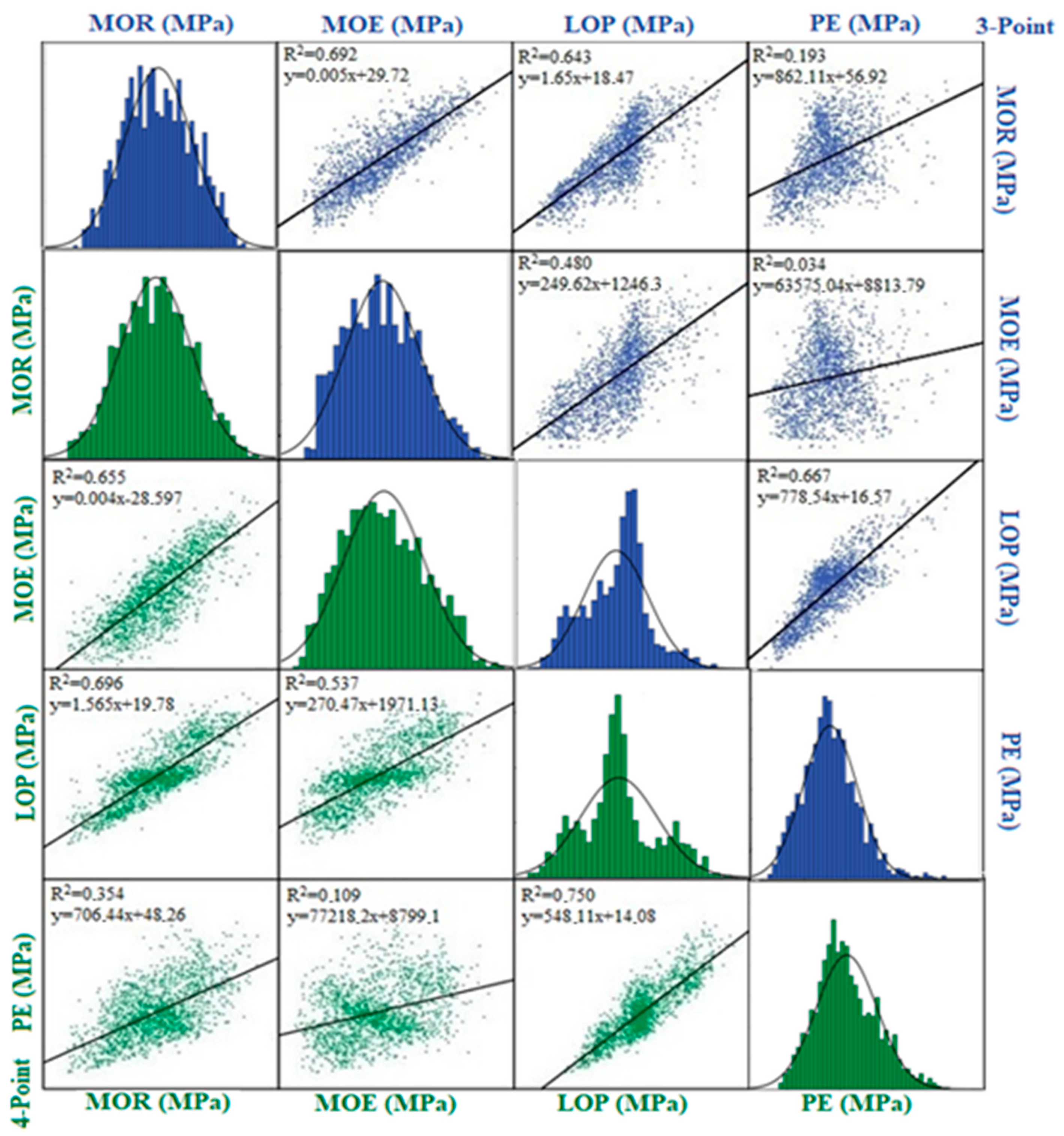
3.1. Regression Matrices for Fir and Black Pine
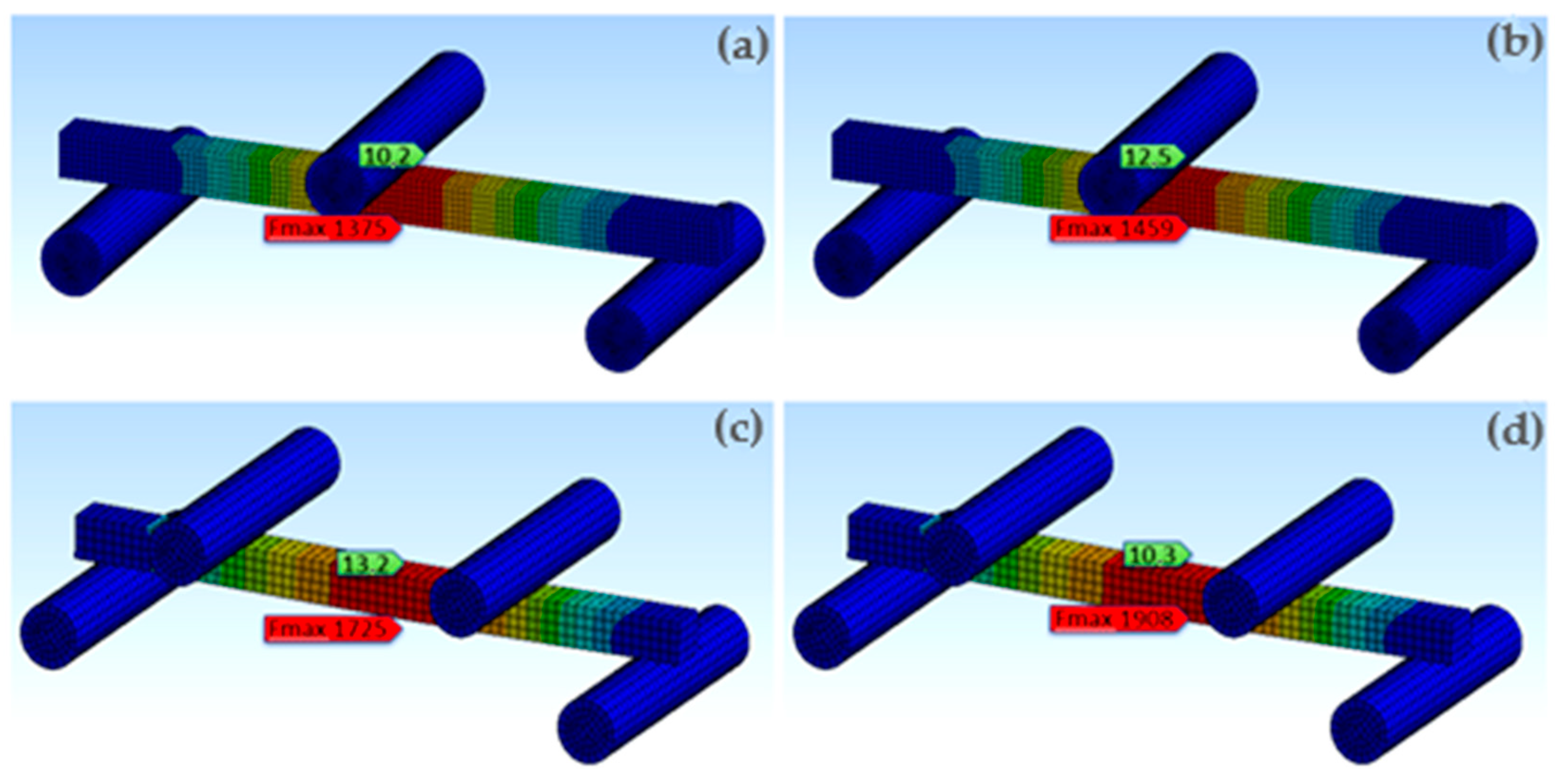
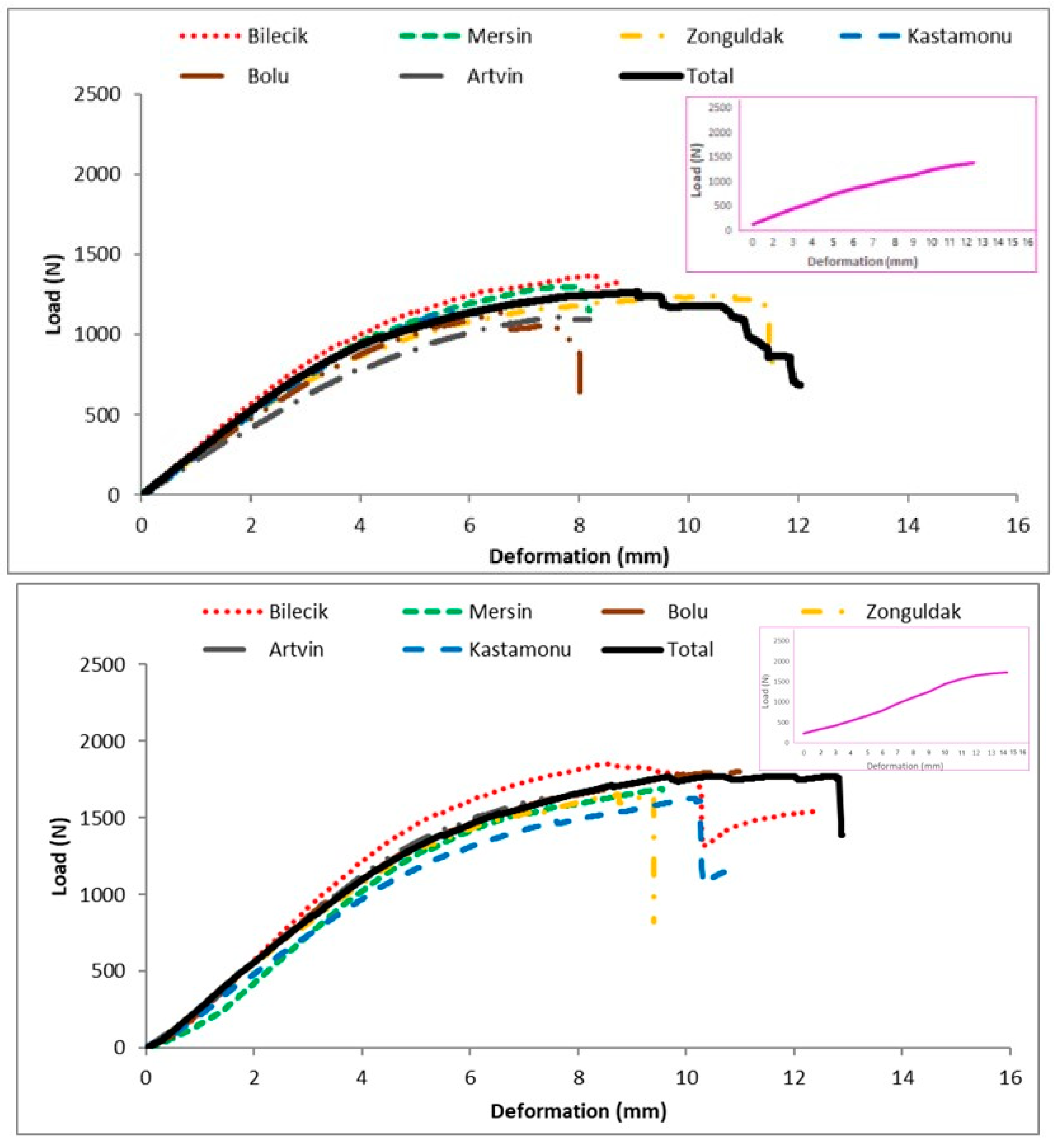
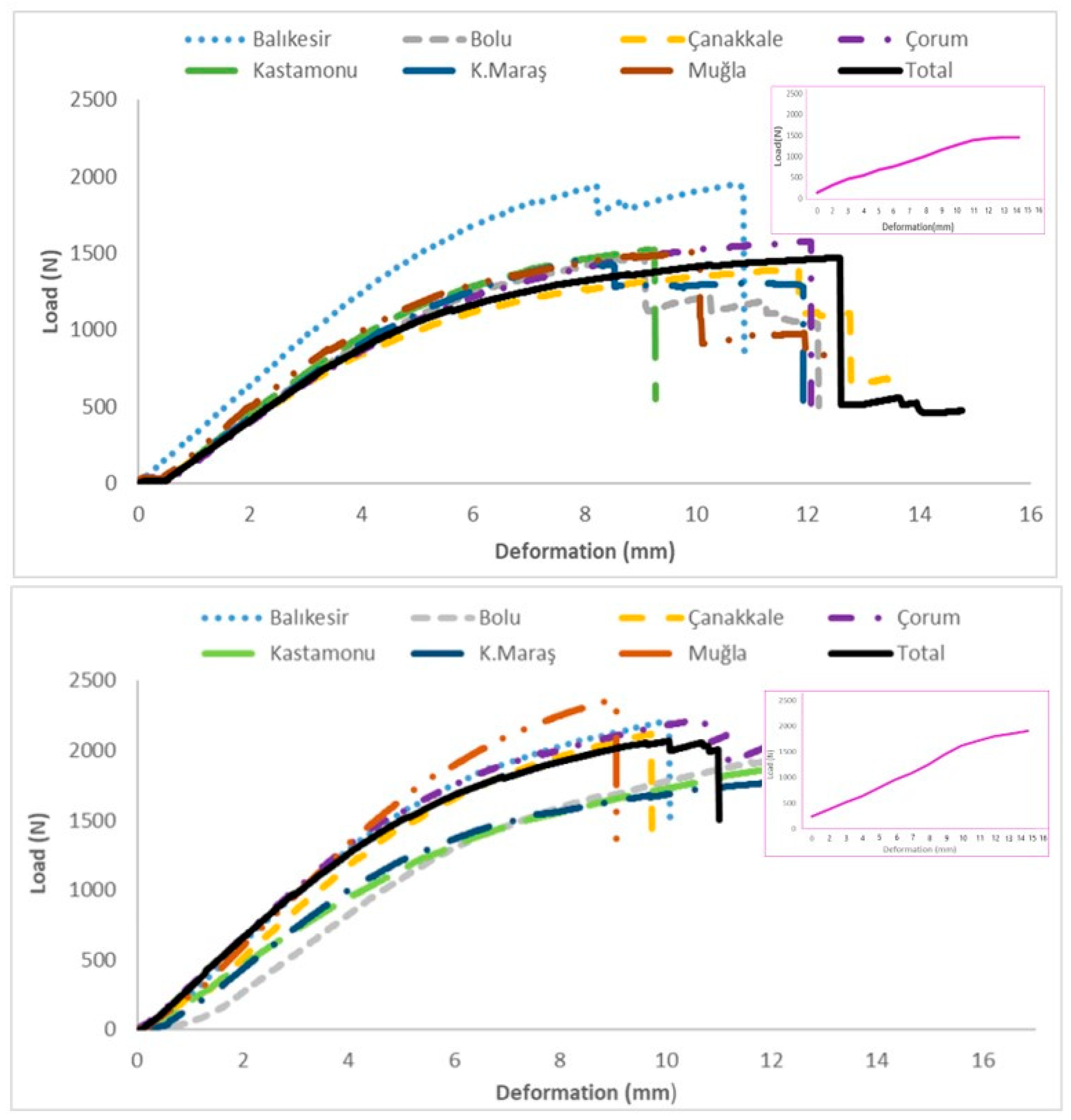
3.2. Numerical Modeling
4. Conclusions
Author Contributions
Funding
Institutional Review Board Statement
Informed Consent Statement
Data Availability Statement
Acknowledgments
Conflicts of Interest
References
- Asif, M. Sustainability of timber, wood and bamboo in construction. In Sustainability of Construction Materials; Elsevier: Amsterdam, The Netherlands, 2009; pp. 31–54. [Google Scholar]
- Gaff, M.; Babiak, M.; Vokatý, V.; Gašparík, M.; Ruman, D. Bending characteristics of hardwood lamellae in the elastic region. Compos. Part B Eng. 2017, 116, 61–75. [Google Scholar] [CrossRef]
- Çetin, F.; Gündüz, G. Türkiye’deki bazı ağaç türü odunlarının mekanik özellikleri üzerine yapılan araştırmaların değerlendirilmesi. Bartın Orman Fakültesi Derg. 2017, 19, 161–181. [Google Scholar]
- Ridley-Ellis, D.; Stapel, P.; Baño, V. Strength grading of sawn timber in Europe: An explanation for engineers and researchers. Eur. J. Wood Wood Prod. 2016, 74, 291–306. [Google Scholar] [CrossRef]
- Goodman, J.R.; Bodig, J. Orthotropic elastic properties of wood. J. Struct. Div. 1970, 96, 2301–2319. [Google Scholar] [CrossRef]
- Burawska-Kupniewska, I.; Krzosek, S.; Mankowski, P.; Grzeskiewicz, M. Quality and Bending Properties of Scots Pine (Pinus sylvestris L.) Sawn Timber. Forests 2020, 11, 1200. [Google Scholar] [CrossRef]
- Kohler, J.; Brandner, R.; Thiel, A.; Schickhofer, G. Probabilistic characterisation of the length effect for parallel to the grain tensile strength of Central European spruce. Eng. Struct. 2013, 56, 691–697. [Google Scholar] [CrossRef]
- Pozgaj, A.; Chovanec, D.; Kurjatko, S.; Babiak, M. Struktura a Vlastnosti Dreva (Structure and Porperties of Wood); Priroda, a.s.: Bratislava, Slovakia, 1997. [Google Scholar]
- Høibø, O.; Vestøl, G.I.; Fischer, C.; Fjeld, L.; Øvrum, A. Bending properties and strength grading of Norway spruce: Variation within and between stands. Can. J. For. Res. 2014, 44, 128–135. [Google Scholar] [CrossRef]
- Niemz, P.; Teischinger, A.; Sandberg, D. Springer Handbook of Wood Science and Technology; Springer: Cham, Switzerland, 2023. [Google Scholar]
- Brancheriau, L.; Bailleres, H.; Guitard, D. Comparison between modulus of elasticity values calculated using 3 and 4 point bending tests on wooden samples. Wood Sci. Technol. 2002, 36, 367–383. [Google Scholar] [CrossRef]
- Lopes, D.A.; da Silva Bertolini, M.; Christoforo, A.L.; Lahr, F.A.R. Influence of testing methods to determine the bending modulus of elasticity of wood. Rev. Vértices 2015, 17, 127–137. [Google Scholar] [CrossRef]
- ISO 13061-3; Physical and Mechanical Properties of Wood—Test Methods for Small Clear Wood Specimens—Part 3: Determination of Ultimate Strength in Static Bending. ISO: Geneva, Switzerland, 2014.
- ISO 13061-4; Physical and Mechanical Properties of Wood—Test Methods for Small Clear Wood Specimens—Part 4: Determination of Modulus of Elasticity in Static Bending. ISO: Geneva, Switzerland, 2014.
- EN 408:2010+A1:2012; Timber Structures—Structural Timber and Glued Laminated Timber—Determination of Some Physical and Mechanical Properties. CEN: Brussels, Belgium, 2012.
- Hein, P.R.G.; Brancheriau, L. Comparison between three-point and four-point flexural tests to determine wood strength of Eucalyptus specimens. Maderas Cienc. Tecnol. 2018, 20, 333–342. [Google Scholar] [CrossRef]
- Sales, C. The rheological study of tropical woods. Modulus of elasticity. Bois For. Trop. 1977, 176, 47–65. [Google Scholar] [CrossRef]
- Babiak, M.; Gaff, M.; Sikora, A.; Hysek, S. Modulus of elasticity in three- and four-point bending of wood. Compos. Struct. 2018, 204, 454–465. [Google Scholar] [CrossRef]
- Gustafsson, S.-I. Mechanical Properties of some Swedish hard wood species. Proc. Inst. Mech. Eng. Part L J. Mater. Des. Appl. 2001, 215, 125–131. [Google Scholar] [CrossRef]
- Yoshihara, H.; Kubojima, Y.; Ishimoto, T. Several examination on the static bending test methods of wood using todomatsu (Japanese fir). For. Prod. J. 2003, 53, 39–44. [Google Scholar]
- EN 310:1993; Wood-Based Panels—Determination of Modulus of Elasticity in Bending and of Bending Strength. British Standards Institution: London, UK, 1993.
- Watanabe, N.; Ogawa, K.; Kobayashi, K. Comparison of the elastic limit and yield load of nailed joints connecting solid wood and wood-based board material. J. Wood Sci. 2022, 68, 42. [Google Scholar] [CrossRef]
- Sikora, A.; Svoboda, T.; Záborský, V.; Gaffová, Z. Effect of selected factors on the bending deflection at the limit of proportionality and at the modulus of rupture in laminated veneer lumber. Forests 2019, 10, 401. [Google Scholar] [CrossRef]
- Wolenski, A.R.V.; Peixoto, R.G.; Aquino, V.B.d.M.; Christoforo, A.L.; Lahr, F.A.R.; Panzera, T.H. Evaluation of mechanical strengths of tropical hardwoods: Proposal of probabilistic models. Eur. J. Wood Wood Prod. 2020, 78, 757–766. [Google Scholar] [CrossRef]
- Haftkhani, A.R.; Abdoli, F.; Sepehr, A.; Mohebby, B. Regression and ANN models for predicting MOR and MOE of heat-treated fir wood. J. Build. Eng. 2021, 42, 102788. [Google Scholar] [CrossRef]
- You, G.; Wang, B.; Li, J.; Chen, A.; Sun, J. The prediction of MOE of bamboo-wood composites by ANN models based on the non-destructive vibration testing. J. Build. Eng. 2022, 59, 105078. [Google Scholar] [CrossRef]
- Rakotovololonalimanana, H.; Chaix, G.; Brancheriau, L.; Ramamonjisoa, L.; Ramananantoandro, T.; Thevenon, M.F. A novel method to correct for wood MOE ultrasonics and NIRS measurements on increment cores in Liquidambar styraciflua L. Ann. For. Sci. 2015, 72, 753–761. [Google Scholar] [CrossRef]
- Baño, V.; Arriaga, F.; Soilán, A.; Guaita, M. Prediction of bending load capacity of timber beams using a finite element method simulation of knots and grain deviation. Biosyst. Eng. 2011, 109, 241–249. [Google Scholar] [CrossRef]
- Berg, S.; Turesson, J.; Ekevad, M.; Huber, J.A. Finite element analysis of bending stiffness for cross-laminated timber with varying board width. Wood Mater. Sci. Eng. 2019, 14, 392–403. [Google Scholar] [CrossRef]
- Olsson, A.; Oscarsson, J.; Serrano, E.; Källsner, B.; Johansson, M.; Enquist, B. Prediction of timber bending strength and in-member cross-sectional stiffness variation on the basis of local wood fibre orientation. Eur. J. Wood Wood Prod. 2013, 71, 319–333. [Google Scholar] [CrossRef]
- Yoshihara, H.; Kubojima, Y. Measurement of the shear modulus of wood by asymmetric four-point bending tests. J. Wood Sci. 2002, 48, 14–19. [Google Scholar] [CrossRef]
- Hasanagić, R.; Fathi, L.; Kapić, Z.; Bahmani, M.; Crnkić, A.; Hrnjica, B.; Humar, M. Experimental and numerical determination of the longitudinal modulus of elasticity in wooden structures. Drew. Pr. Nauk. Doniesienia Komun. 2022, 65, 210. [Google Scholar] [CrossRef]
- Fajdiga, G.; Rajh, D.; Nečemer, B.; Glodež, S.; Šraml, M. Experimental and numerical determination of the mechanical properties of spruce wood. Forests 2019, 10, 1140. [Google Scholar] [CrossRef]
- Kurul, F.; Şişman, Ö.A.; Dündar, T. Mechanical characterization of visually graded boards from turkish fir and black pine by nondestructive and destructive tests. Maderas Cienc. Y Tecnol. 2024, 26, e1724. [Google Scholar] [CrossRef]
- TS 1265; Sawn Timber (Coniferous)—For Building Construction. TSE: Ankara, Turkey, 2012.
- Edgars, L.; Kaspars, Z.; Kaspars, K. Structural performance of wood based sandwich panels in four point bending. Procedia Eng. 2017, 172, 628–633. [Google Scholar] [CrossRef]
- Müller, U.; Jost, T.; Kurzböck, C.; Stadlmann, A.; Wagner, W.; Kirschbichler, S.; Baumann, G.; Pramreiter, M.; Feist, F. Crash simulation of wood and composite wood for future automotive engineering. Wood Mater. Sci. Eng. 2020, 15, 312–324. [Google Scholar] [CrossRef]
- ISO 3129; Wood-Sampling Methods and General Requirements for Physcial and Mechanical Testing of Small Clear Wood Specimens. ISO: Geneva, Switzerland, 2019.
- Mujika, F. On the effect of shear and local deformation in three-point bending tests. Polym. Test. 2007, 26, 869–877. [Google Scholar] [CrossRef]
- Ross, R.J.; Brashaw, B.K.; Pellerin, R.F. Nondestructive evaluation of wood. For. Prod. J. 1998, 48, 14–19. [Google Scholar]
- ISO 13061-2; Physical and Mechanical Properties of Wood—Test Methods for Small Clear Wood Specimens—Part 2: Determination of Density for Physical and Mechanical Tests. ISO: Geneva, Switzerland, 2014.
- ISO 13061-1; Physical and Mechanical Properties of Wood—Test Methods for Small Clear Wood Specimens—Part 1: Determination of Moisture Content for Physical and Mechanical Tests. ISO: Geneva, Switzerland, 2014.
- Kollmann, F.F.; Côté, W.A., Jr. Principles of Wood Science and Technology. Vol. I. Solid Wood; Springer: Berlin/Heidelberg, Germany, 1968. [Google Scholar]
- Guerrin, G.M. Caractérisation en Flexion QUASI Statique et Dynamique d’un Matériau Thermo-Hygroviscoélastique: Le Bois. Ph.D. Thesis, Institut National Polytechnique de Lorraine, Nancy, France, 1990. [Google Scholar]


| Species | Regional Forest Directorates | Number of Specimens | Species | Regional Forest Directorates | Number of Specimens |
|---|---|---|---|---|---|
| Fir | Artvin | 545 | Black pine | Balıkesir | 545 |
| Bilecik | 357 | Bolu | 339 | ||
| Bolu | 704 | Çanakkale | 374 | ||
| Kastamonu | 343 | Çorum | 390 | ||
| Mersin | 323 | Kahramanmaraş | 444 | ||
| Zonguldak | 368 | Kastamonu | 458 | ||
| Muğla | 466 | ||||
| Subtotal | 2640 | Subtotal | 3016 | ||
| Total 5656 | |||||
| Tests | Method | Region | Total | |||||
|---|---|---|---|---|---|---|---|---|
| Artvin | Bilecik | Bolu | Kastamonu | Mersin | Zonguldak | |||
| Sample Number (pcs.) | 3p | 205 | 140 | 225 | 162 | 150 | 179 | 1061 |
| 4p | 340 | 217 | 479 | 181 | 173 | 189 | 1579 | |
| ρ12 (kg/m3) | - | 392 | 426 | 421 | 418 | 443 | 417 | 417.4 |
| MC (%) | - | 11.6 | 11.3 | 11.0 | 11.8 | 12.0 | 11.8 | 11.5 |
| MOR (MPa) | 3p | 55.2 a (14.0) | 63.2 cd (12.9) | 58.6 b (12.7) | 59.4 b (14.0) | 64.0 d (16.5) | 61.8 c (15.4) | 60.0 1 (15.1) |
| 4p | 58.6 a (14.2) | 66.5 d (14.5) | 62.7 c (14.2) | 57.9 a (14.2) | 62.3 c (18.2) | 60.4 b (15.5) | 61.5 2 (15.2) | |
| MOE (MPa) | 3p | 7640 a (20.1) | 9113 d (15.0) | 8066 b (17.0) | 8048 b (17.0) | 8603 c (21.2) | 8646 c (16.7) | 8293 1 (18.7) |
| 4p | 10,475 b (20.0) | 12,303 d (18.0) | 11,549 c (16.0) | 9139 a (16.7) | 10,434 b (21.8) | 10,359 b (20.5) | 10,880 2 (20.2) | |
| MOEa (MPa) | 3p | 7096 a (18.8) | 8350 d (13.9) | 7470 b (15.8) | 7458 b (15.5) | 7867 c (20) | 7964 c (15.3) | 7651 1 (17.4) |
| 4p | 9776 b (18.7) | 11,340 d (16.4) | 10,706 c (14.9) | 8607 a (15.8) | 9740 b (20.3) | 9709 b (19.2) | 10,127 2 (18.8) | |
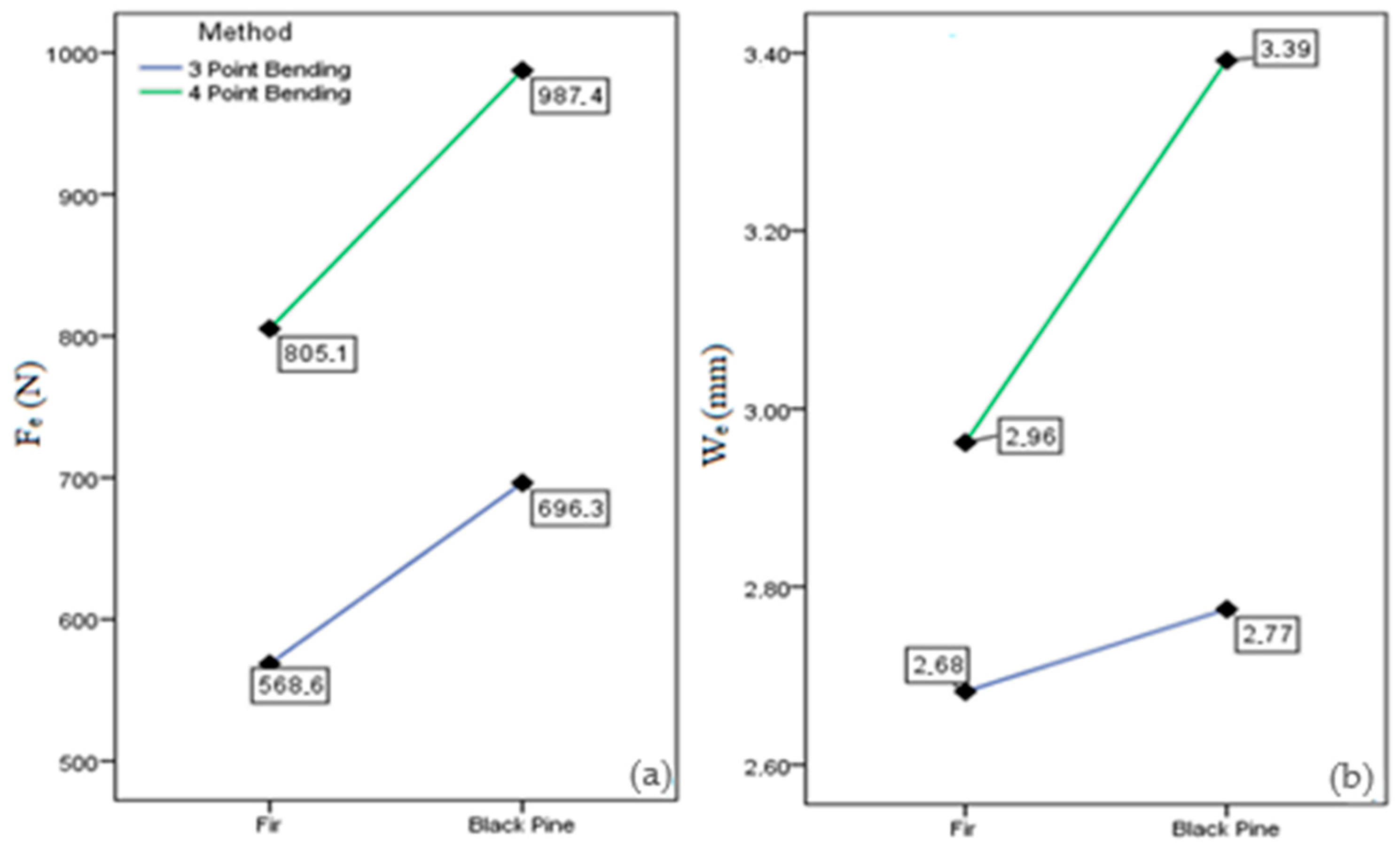
| Fe (N) | 3p | 541.6 a (19.5) | 598.1 c (17.4) | 550.1 a (16.8) | 564.6 ab (18.0) | 596.5 c (19.8) | 579.7 bc (17.5) | 568.6 1 (18.5) |
| 4p | 784.9 b (18.7) | 878.9 d (17.1) | 817.6 c (16.1) | 747.6 a (17.1) | 795.7 bc (19.9) | 788.9 b (18.0) | 805.1 2 (18.1) | |
| We (mm) | 3p | 2.77 cd (17.9) | 2.51 a (13.6) | 2.63 b (15.1) | 2.72 bc (14.0) | 2.83 d (16.8) | 2.63 b (15.8) | 2.68 1 (16.1) |
| 4p | 3.01 b (15.0) | 2.80 a (15.4) | 2.85 a (13.4) | 3.15 c (15.8) | 3.05 b (17.3) | 3.07 b (15.7) | 2.96 2 (15.6) | |
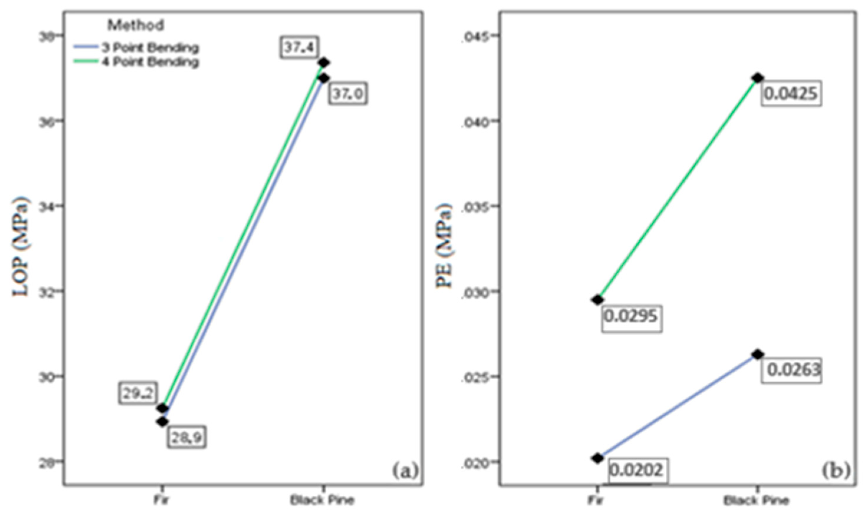
| LOP (MPa) | 3p | 27.8 a (19.4) | 29.9 c (16.2) | 28.2 b (16.4) | 28.6 ab (16.4) | 30.4 c (19.8) | 29.6 bc (17.7) | 28.9 1 (18.2) |
| 4p | 28.7 b (18.7) | 31.6 d (17.1) | 29.8 c (15.9) | 27.0 a (17.1) | 28.9 bc (20.0) | 28.7 b (18.7) | 29.2 1 (18.0) | |
| PE (MPa) | 3p | 0.0202 a (37.8) | 0.0194 a (28.8) | 0.0192 a (35.2) | 0.0202 a (32.8) | 0.0227 b (32.5) | 0.0200 a (34.7) | 0.0202 1 (34.5) |
| 4p | 0.0295 a (30.3) | 0.0305 a (29.2) | 0.0287 a (28.4) | 0.0291 a (31.6) | 0.0301 a (31.8) | 0.0303 a (31.8) | 0.0295 2 (30.2) | |
| Tests | Method | Region | Total | ||||||
|---|---|---|---|---|---|---|---|---|---|
| Balıkesir | Bolu | Çanakkale | Çorum | K.Maraş | Kastamonu | Muğla | |||
| Sample Number (pcs.) | 3p | 275 | 174 | 189 | 195 | 228 | 234 | 230 | 1525 |
| 4p | 270 | 165 | 185 | 195 | 216 | 224 | 236 | 1491 | |
| ρ12 (kg/m3) | - | 532 | 570 | 563 | 580 | 505 | 530 | 586 | 550.4 |
| MC (%) | - | 11.3 | 11.3 | 11.5 | 11.6 | 11.0 | 11.4 | 11.3 | 11.3 |
| MOR (MPa) | 3p | 83.3 c (13.2) | 78.2 b (16.1) | 79.0 b (17.6) | 82.8 c (13.4) | 71.8 a (15.6) | 77.7 b (14.2) | 83.2 c (18.5) | 79.5 1 (16.3) |
| 4p | 83.2 c (12.9) | 74.2 b (17.1) | 76.4 b (12.9) | 83.3 c (12.9) | 70.3 a (15.4) | 74.1 b (14.9) | 84.1 c (20.0) | 78.3 1 (17.5) | |
| MOE (MPa) | 3p | 11,428 d (16.5) | 9919 b (22.1) | 10,449 c (25.8) | 10,362 c (21.2) | 9330 a (19.4) | 10,293 bc (17.6) | 11,238 d (22.6) | 10,481 1 (21.6) |
| 4p | 13,358 d (16.2) | 11,008 b (23.0) | 11,921 c (25.2) | 12,169 c (19.9) | 10,600 a (21.2) | 11,657 c (18.7) | 13,199 d (22.8) | 12,084 2 (22.3) | |
| MOEa (MPa) | 3p | 10,293 d (14.9) | 9044 b (20.3) | 9480 c (23.6) | 9411 c (19.3) | 8551 a (17.7) | 9362 bc (16.0) | 10,129 d (20.5) | 9509 1 (19.7) |
| 4p | 12,272 d (14.9) | 10,255 b (21.5) | 11,034 c (23.5) | 11,257 c (18.4) | 9892 a (19.7) | 10,814 c (17.4) | 12,123 d (21.1) | 11,175 2 (20.7) | |
| Fe (N) | 3p | 729.5 c (12.4) | 676.3 b (18.9) | 677.9 b (19.7) | 715.4 c (13.4) | 649.7 a (17.8) | 690.4 b (16.1) | 723.0 c (20.3) | 696.3 1 (17.4) |
| 4p | 1049.7 cd (16.9) | 900.0 a (20.7) | 923.8 a (21.5) | 1048.6 c (16.6) | 899.8 a (17.1) | 962.1 b (16.5) | 1080.6 d (21.5) | 987.4 2 (19.9) | |
| We (mm) | 3p | 2.67 a (12.1) | 2.79 bc (14.5) | 2.76 bc (16.3) | 2.88 d (15.0) | 2.84 cd (15.5) | 2.79 bc (13.0) | 2.74 ab (15.9) | 2.77 1 (14.8) |
| 4p | 3.24 a (10.1) | 3.46 cd (15.8) | 3.32 ab (15.5) | 3.54 d (14.7) | 3.43 c (15.9) | 3.38 bc (12.8) | 3.45 cd (14.3) | 3.39 2 (14.4) | |
| LOP (MPa) | 3p | 38.6 c (12.3) | 36.0 b (18.3) | 36.4 b (19.4) | 37.9 c (12.7) | 34.6 a (17.7) | 36.7 b (15.8) | 38.3 c (20.2) | 37.0 1 (17.0) |
| 4p | 39.6 de (16.0) | 34.1 ab (20.3) | 35.2 bc (20.8) | 39.7 d (15.9) | 34.1 a (16.9) | 36.3 c (16.0) | 40.8 e (18.1) | 37.4 1 (19.5) | |
| PE (MPa) | 3p | 0.0263 a (22.1) | 0.0260 a (27.4) | 0.0252 a (30.8) | 0.0282 b (23.2) | 0.0253 a (29.7) | 0.0264 a (25.5) | 0.0268 a (32.3) | 0.0263 1 (27.5) |
| 4p | 0.0430 c (22.3) | 0.0397 ab (31.0) | 0.0390 ab (27.9) | 0.0469 d (25.4) | 0.0393 a (27.3) | 0.0411 bc (24.9) | 0.0472 d (30.4) | 0.0425 2 (27.9) | |
| Species | Point | Experimental Results | Analysis Results | % Dif. Fmax | % Dif. Wmax | ||
|---|---|---|---|---|---|---|---|
| Fmax (N) | Wmax (mm) | Fmax (N) | Wmax (mm) | ||||
| Fir | 3 | 1297.2 | 9.5 | 1375 | 10.2 | 6.00 | 7.37 |
| 4 | 1774.2 | 12.7 | 1725 | 13.2 | −2.77 | 3.94 | |
| Black Pine | 3 | 1469.5 | 12.6 | 1459 | 12.5 | −0.71 | −0.79 |
| 4 | 2066.1 | 10.1 | 1908 | 10.3 | −7.65 | 1.98 | |
Disclaimer/Publisher’s Note: The statements, opinions and data contained in all publications are solely those of the individual author(s) and contributor(s) and not of MDPI and/or the editor(s). MDPI and/or the editor(s) disclaim responsibility for any injury to people or property resulting from any ideas, methods, instructions or products referred to in the content. |
© 2025 by the authors. Licensee MDPI, Basel, Switzerland. This article is an open access article distributed under the terms and conditions of the Creative Commons Attribution (CC BY) license (https://creativecommons.org/licenses/by/4.0/).
Share and Cite
Kurul, F.; Görgün, H.V.; Şeker, S.; Yılmaz, T.; Dündar, T.; Ayrilmis, N. Experimental and Numerical Modeling of Bending Characteristics of Fir and Black Pine Wood from Different Forest Regions in Türkiye. Forests 2025, 16, 844. https://doi.org/10.3390/f16050844
Kurul F, Görgün HV, Şeker S, Yılmaz T, Dündar T, Ayrilmis N. Experimental and Numerical Modeling of Bending Characteristics of Fir and Black Pine Wood from Different Forest Regions in Türkiye. Forests. 2025; 16(5):844. https://doi.org/10.3390/f16050844
Chicago/Turabian StyleKurul, Fatih, Hızır Volkan Görgün, Sedanur Şeker, Tülay Yılmaz, Türker Dündar, and Nadir Ayrilmis. 2025. "Experimental and Numerical Modeling of Bending Characteristics of Fir and Black Pine Wood from Different Forest Regions in Türkiye" Forests 16, no. 5: 844. https://doi.org/10.3390/f16050844
APA StyleKurul, F., Görgün, H. V., Şeker, S., Yılmaz, T., Dündar, T., & Ayrilmis, N. (2025). Experimental and Numerical Modeling of Bending Characteristics of Fir and Black Pine Wood from Different Forest Regions in Türkiye. Forests, 16(5), 844. https://doi.org/10.3390/f16050844