Article

Global Navigation Satellite System/Inertial Navigation System-Based Autonomous Driving Control System for Forestry Forwarders

1
Forest Technology and Management Research Center, National Institute of Forest Science, Pocheon 11187, Republic of Korea
2
Department of Biosystems Engineering, Kangwon National University, Chuncheon 24341, Republic of Korea
3
Interdisciplinary Program in Smart Agriculture, Graduate School, Kangwon National University, Chuncheon 24341, Republic of Korea
*
Authors to whom correspondence should be addressed.
Forests 2025, 16(4), 647; https://doi.org/10.3390/f16040647
Submission received: 31 January 2025 / Revised: 25 March 2025 / Accepted: 4 April 2025 / Published: 8 April 2025

Abstract

:
Logging operations comprise a repeated and tedious job in forestry operations because forestry forwarders must keep completing round-trip transportation on forest roads from tree-cutting sites to forest roads where their truck can be accessed. In this study, an autonomous driving system for tracked forwarders was developed using GNSS (Global Navigation Satellite System)/INS (Inertial Navigation System). The mechanical control system of the forwarder was replaced with an electronic control system, and path-planning and -tracking algorithms were implemented. The electronic control system, operated by servo motors to operate the driving levers, exhibited a response that was 150 milliseconds faster in lever control compared to manual operation. To generate an autonomous driving path, a skilled operator drove the forwarder along a forest road, and the recorded path was post-processed using the Novatel Inertial Explorer 8.70 GNSS + INS software to minimize GNSS errors. The autonomous forwarder followed the generated path using the pure pursuit algorithm. Autonomous driving tests conducted along this path achieved a root mean square error (RMSE) within 0.4 m (range: 0.389–0.393). Driving errors were primarily attributed to GNSS positional inaccuracies, especially in environments with dense canopies and landslide prevention structures located higher than the GNSS antenna, obstructing satellite signals. These findings underscore the importance and feasibility of autonomous forwarders in diverse forest environments, providing a critical foundation for advancing autonomous forestry machinery. The proposed technologies are expected to significantly contribute to enhancing the productivity of forestry operations.

1. Introduction

Wood is a renewable and eco-friendly resource that has garnered increasing attention as an alternative energy source. Demand for wood continues to grow due to climate change, resource scarcity, and population growth [1]. The rising interest in carbon neutrality and environmental protection has further accelerated the use of wood as a sustainable energy resource. However, forestry operations are often classified as 3D (dirty, difficult, dangerous), and it is increasingly difficult to attract younger workers. Labor shortage, combined with an aging workforce, has resulted in declining productivity and rising labor costs, adding significant strain to forestry operations [2,3].
Addressing these challenges by finding ways to increase wood production while improving worker health and safety has become a critical priority in the forestry sector [4,5,6]. Autonomous driving systems for transportation devices such as forwarders have proven to be highly effective in boosting wood production efficiency while enhancing worker safety [7]. Over the years, autonomous driving systems have made significant advancements and have been successfully applied in fields such as automobiles and agricultural machinery [8,9,10,11,12]. In the forestry machinery sector, extensive research is underway to promote their application, making this a highly promising area with considerable potential [13].
A forwarder is a vehicle designed to transport timber from harvesting sites to loading areas, where further processing and loading occur, or directly to forest roads [14,15]. The transport of timber from loading areas to roadsides via forest roads is typically carried out using forwarders, trucks, and skidders. In mountainous regions, forest roads are often characterized by landslide prevention structures located higher than the GNSS antenna, posing considerable safety risks to operators [16]. Additionally, forwarders frequently operate in unpredictable environments, including flat roads, rugged terrain, and dense forests, presenting considerable challenges for manual operation by human operators [17]. The integration of autonomous driving systems into forestry machinery helps reduce reliance on human operators, mitigate risks associated with hazardous working conditions, and optimize the operational efficiency of tasks such as tree felling and timber transportation [15,18].
Autonomous driving systems leverage advanced sensors, machine learning algorithms, and real-time data processing to navigate complex environments and make decisions comparable to, or even exceeding, human capabilities. Despite these evident advantages, their deployment in forestry machinery presents significant challenges. These include the need for robust sensor technologies capable of withstanding harsh environmental conditions, the development of advanced algorithms for real-time decision making, and the seamless integration of these systems into existing forestry operations [19,20]. Ongoing research strives to improve productivity and efficiency while simultaneously addressing the persistent labor shortage, despite these challenges.
Visser et al. [18] reported that self-driving forestry trucks are being extensively developed and are likely to be introduced here, earlier than in other industries, given that forestry trucks typically operate between fixed destinations, such as forests and sawmills, without the complexities of navigating urban environments. Hera et al. [20] noted that autonomous driving in forest environments involves harsher conditions than on regular roads or farmland. Autonomous systems heavily rely on precise positional information from sensors, but in forest environments, Global Navigation Satellite System (GNSS) signals may be obstructed by trees, slopes, and steep gradients. To address these challenges, sensor fusion and simultaneous localization and mapping (SLAM) techniques have been suggested for path planning and autonomous driving [21]. However, during the construction of most forest roads, trees are felled along the planned route, removing tree canopies and potentially allowing for improved GNSS signal reception compared to dense forest conditions. This study aimed to validate the applicability of autonomous forwarders in environments where trees and canopies have been removed due to timber harvesting and road construction. To achieve this, the following three objectives were established: (1) development of a system (for existing forwarders) to convert the mechanical control into electronic control for autonomous driving; (2) development of path-generation and path-tracking algorithms for GNSS-based autonomous driving; and (3) development of performance evaluation approaches on forest roads using the developed system and algorithms.
This study is expected to significantly contribute to improving productivity by enabling autonomous operation of forestry forwarders in the harsh forest road where sloped terrain exists and satellite signals may be poor due to tree canopy.

2. Materials and Methods

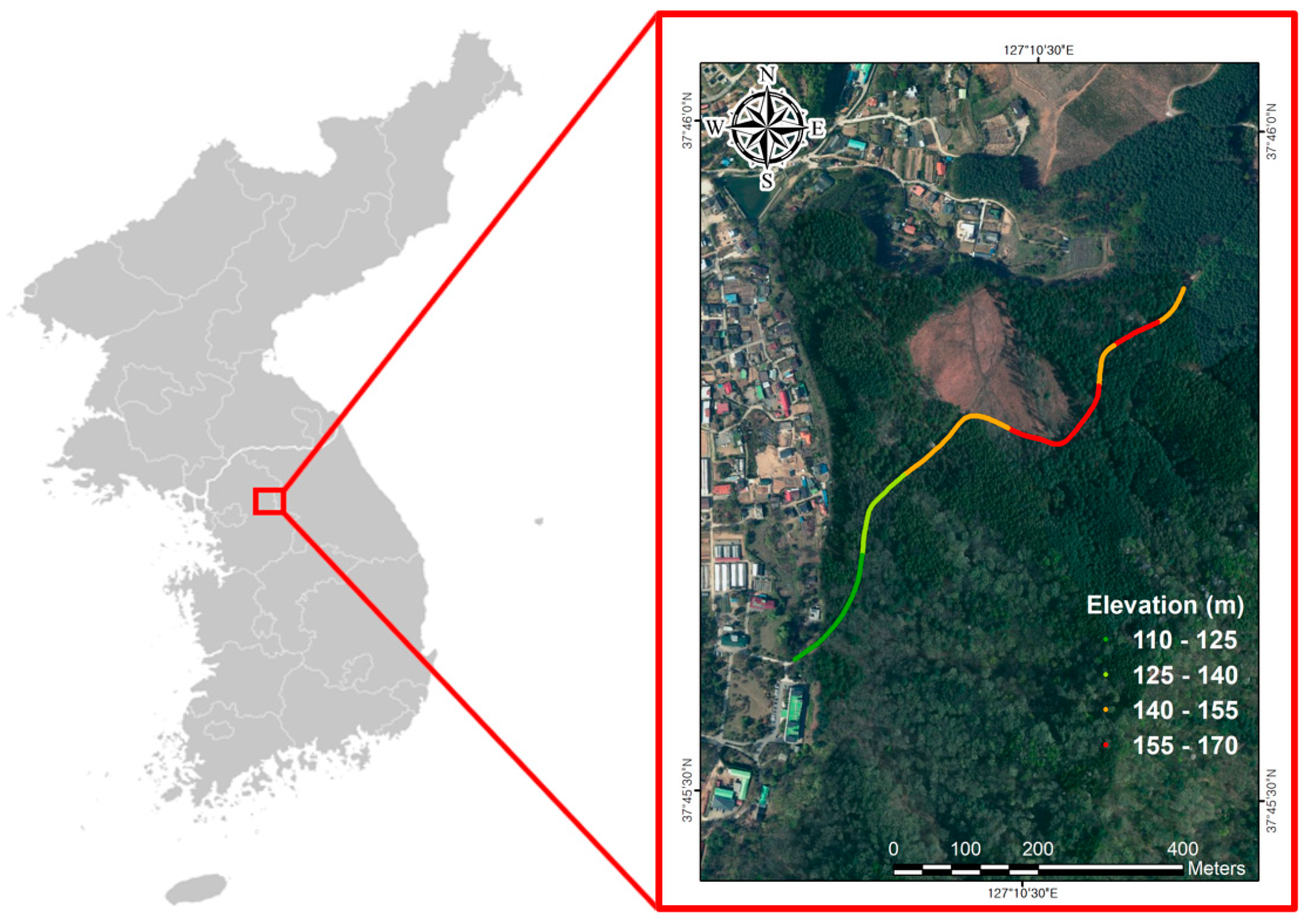
2.1. Experimental Site

The target area for autonomous driving in this study is a 1.5 km section (127°10′31.687″ E, 37°45′45.975″ N) of a forest road near Jikdong-ri, Soheul-eup, Pocheon, Gyeonggi-do, South Korea. In order to verify various environments that may affect GNSS/INS-based autonomous driving, the target area was set to have various terrains, tree species, and canopy changes. Figure 1 shows the altitude of the driving route in the target area, and the terrain and forest conditions are as shown in Table 1.

2.2. Development of the Autonomous Driving Control System

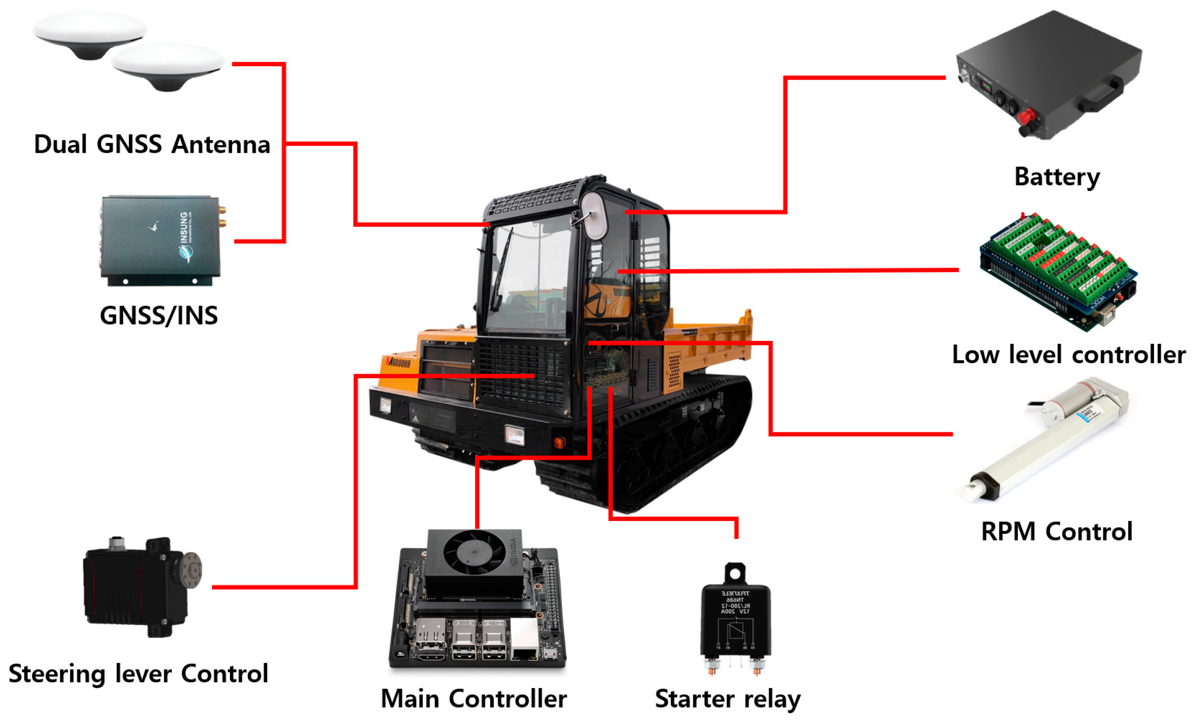
2.2.1. Overview of the Driving Control System

An autonomous driving control system was developed to enable forwarders, traditionally operated using mechanical controls, to function autonomously. The system comprises three main components: a controller, GNSS (Global Navigation Satellite System)/INS (Inertial Navigation System), and actuators, as depicted in Figure 2. The forwarder utilized in this study, a 2009 model, originally relied on a mechanically controlled driving system. To transition to electronic control, actuators with electronic motors were installed to manage the driving and acceleration levers. The control system is structured with a main controller and a lower-level controller. The main controller receives data from GNSS/INS and processes them to determine the vehicle path and speed. It then transmits commands to the lower-level controller. The lower-level controller executes these commands by operating actuators such as servo motors and linear actuators, which manage steering, acceleration, and braking. The flow of control and power between the control modules and interface modules is illustrated in Figure 3.

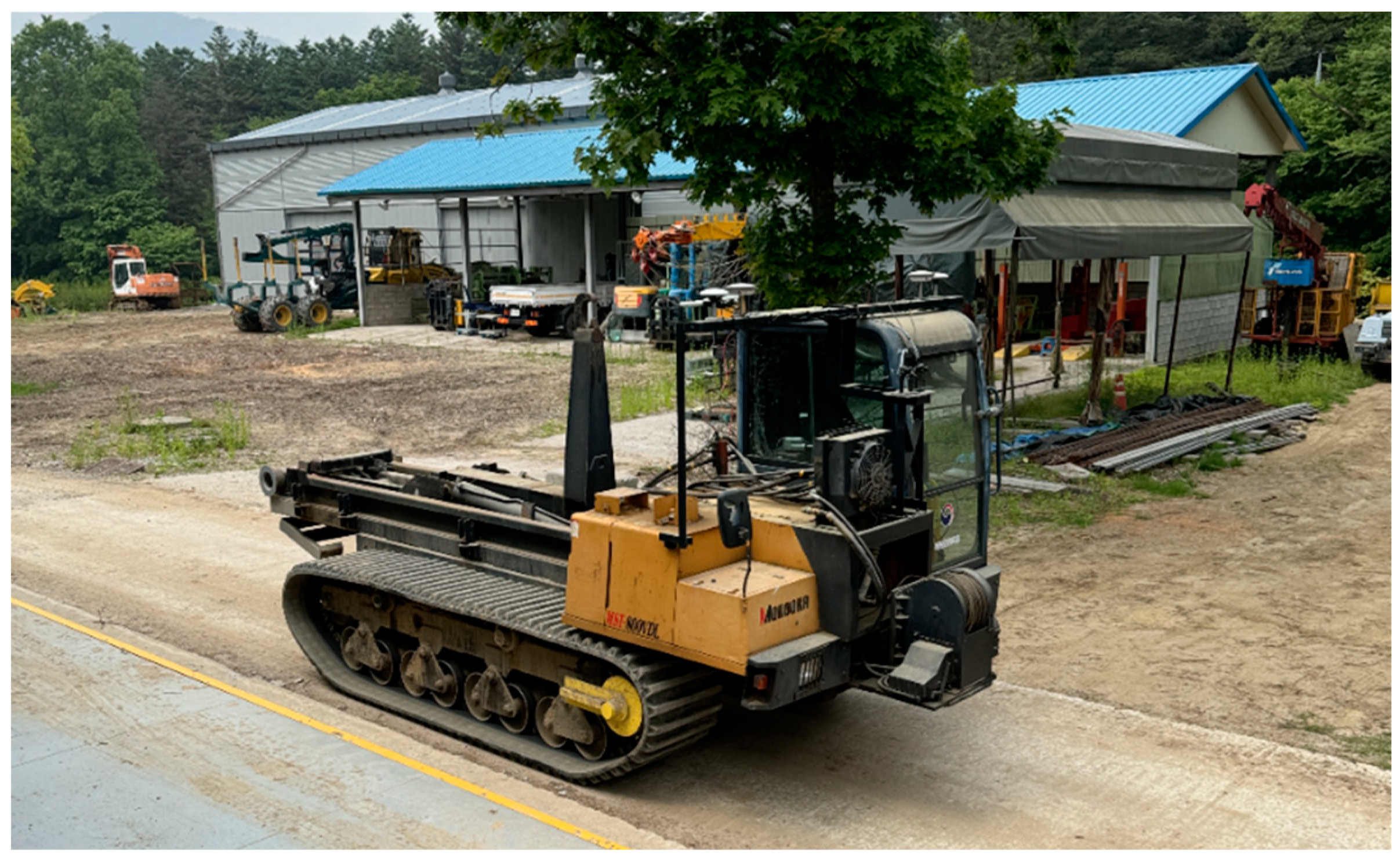
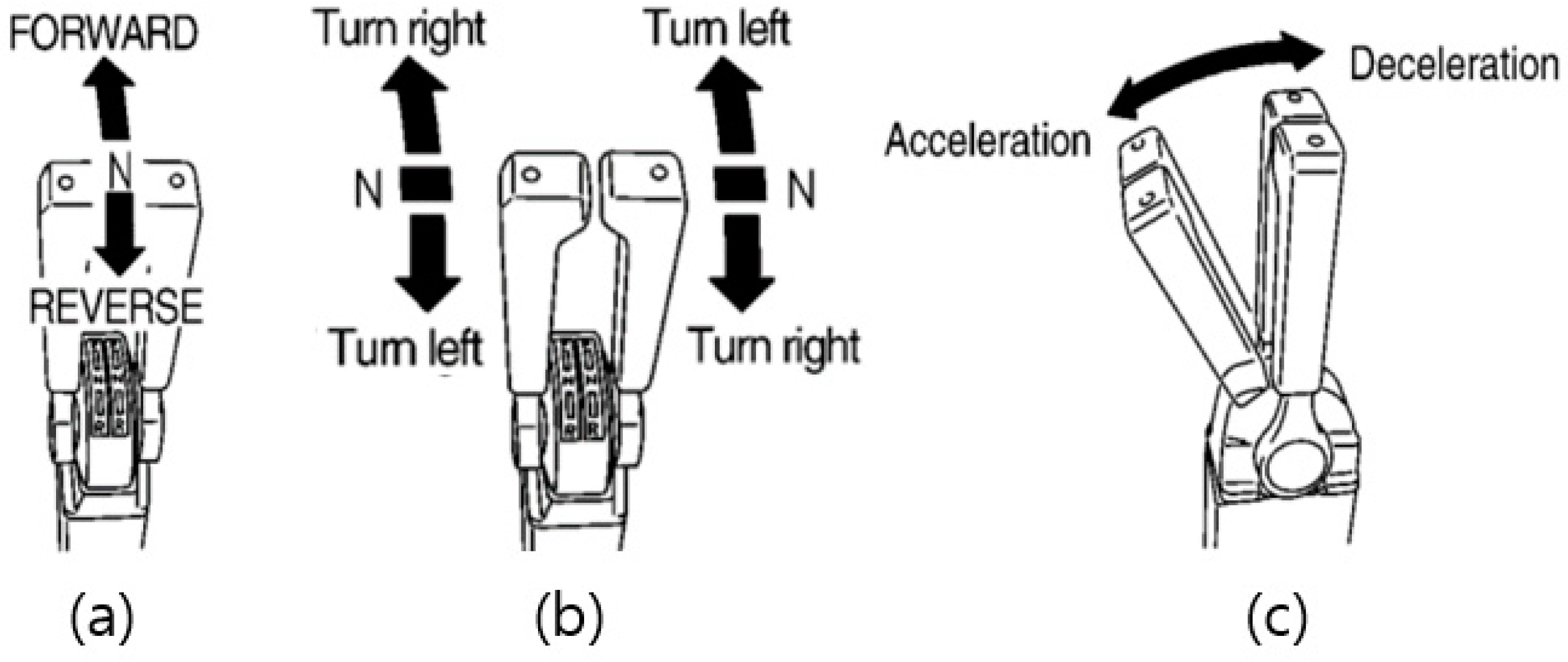
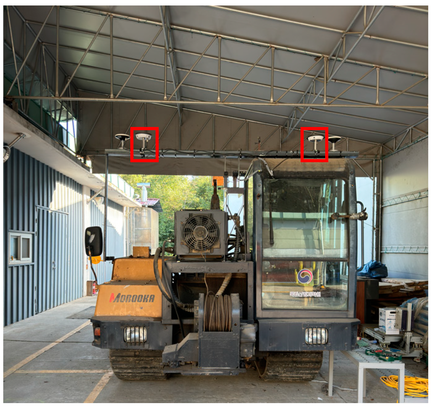
2.2.2. Tracked Forwarder (Reference Vehicle)

The MST 800VDL (MOROOKA, Ryugasaki, Japan) tracked forwarder was used as the standard reference model in this study. This model is equipped with hydrostatic transmission (HST) and relies entirely on mechanical controls. To facilitate electronic control, the forwarder was retrofitted with electronic actuators and additional components, as described in the previous section. The design and specifications of the tracked forwarder are illustrated in Figure 4 and detailed in Table 2.

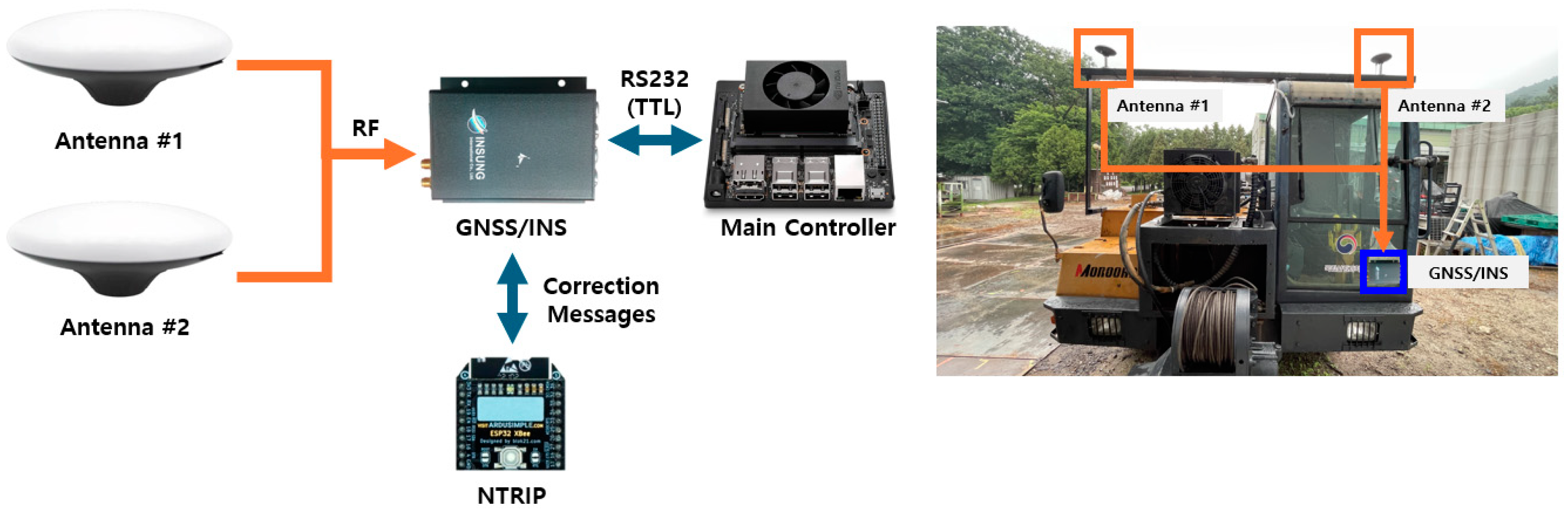
2.2.3. RTK GNSS/INS System for Autonomous Forwarder

A real-time kinematics (RTK) GNSS-based INS was implemented to ensure precise positioning of the forwarder. The standard GNSS determines location through triangulation from signals received from four or more satellites and is prone to meter-level errors caused by external factors, whereas the RTK-GNSS delivers centimeter-level accuracy. This precision is achieved by using a base station with known coordinates to compute GNSS phase errors and transmit correction signals to a moving station. Owing to the challenges of installing a base station for each forest operation, a virtual reference station–GNSS system was used; it received correction signals via a mobile network from a virtual base station server provided by the South Korean National Geographic Information Institute. The RTK-based INS utilizes the PIM222A receiver (Novatel, Calgary, AB, Canada), capable of receiving signals from L1, L2, Galileo, and Beidou satellites. It supports dual-antenna reception for enhanced accuracy and achieves a yaw error of only ±0.5°. In addition, SPAN GNSS + INS technology combines GNSS absolute positioning with orientation and attitude data (roll, pitch, yaw), ensuring reliable positioning even in environments with unstable GNSS signals, such as forests. The system configuration and antenna installation are as shown in Figure 5. RTK-GNSS can be configured with the correction signal generated from NTRIP to receive high-level position values. The position information is transmitted to the main controller through TTL-level RS232 communication. Table 3, Table 4 and Table 5 provide the specifications for the antenna (GPS-713-GGG-N, Novatel, Calgary, AB, Canada), networked transport of Radio Technical Commission for Maritime Services (RTCM) via Internet Protocol (NTRIP) (WiFi NTRIP Master, ArduSimple, Andorra la Vella, Andorra), and GNSS/INS.

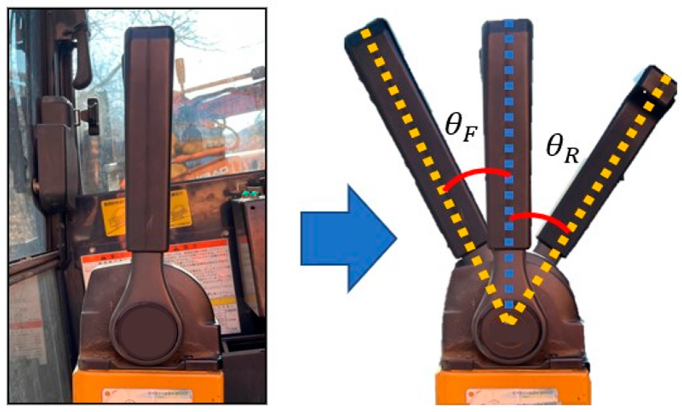
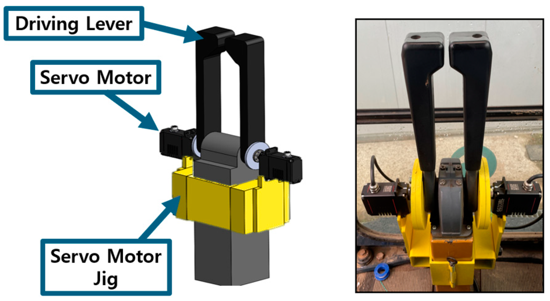
2.2.4. Control System for Driving Lever

To implement autonomous driving, a system was developed to automatically operate the forwarder’s driving levers based on steering and speed commands from the main controller. Tracked forwarders typically use separate left- and right-driving levers, which control the swashplate angle of the HST using wires (Figure 6). This mechanism determines the rotational speed and direction of the hydraulic motors, thereby controlling the forwarder driving direction and speed. Figure 6a illustrates the lever operation in the neutral position (forwarder at a standstill). To move straight, both levers are pushed forward simultaneously, while for reverse, both levers are pulled back simultaneously. For a left turn, as shown in Figure 6b, only the left driving lever is pushed forward. In cases where a smaller turning radius is required, the left driving lever is pushed forward while the right driving lever is pulled back simultaneously. As depicted in Figure 6c, the driving levers also function like an accelerator pedal, controlling the forwarder’s driving speed.
The mechanical driving levers installed on the forwarder have different operating ranges for forward and reverse directions, owing to their mechanical characteristics, and these require significant torque for operation. Therefore, the operating range and maximum torque of the current steering lever were measured to select an appropriate servo motor, as shown in Figure 7. The operating range of the steering lever was found to be 32.95° in the forward direction and 37.35° in the reverse direction, with a maximum operating torque of 9.41 N·m. The SG33BLT-CAN servo motor (Hitec, Seoul, Republic of Korea) was selected based on these parameters (Table 6).
As shown in Figure 8, the jig for the servo motor was designed and installed, and the rotation axis of the servo motor was aligned with the central axis of the left and right drive levers to ensure the smooth control of the driving lever. The servo motor was firmly fixed to the left and right sides with jigs. To ensure precise position control, a magnetic encoder embedded in the servo motor was employed, and each servo motor was assigned a unique ID to prevent malfunctions. Additionally, the operating range was restricted to 0.5° less than the actual forward and reverse ranges—to prevent motor overload and overrun.

2.3. Autonomous Driving Algorithm

2.3.1. Path Planning

For an unmanned forwarder to navigate a predefined forest road, a path must be established from the starting point to the destination. In typical autonomous tractors used for agricultural operations, with predefined work areas, path-planning algorithms such as A*, Dijkstra, and D* are employed to generate an optimal path based on the type of equipment and working radius [22]. However, in forestry operations using forwarders, the primary objective is timber transport along existing forest roads, which necessitates the creation of transport paths. Owing to tree canopies and complex terrain, driving paths using aerial images is challenging. In this study, the driving path for the autonomous vehicle was established by having a skilled operator drive the forwarder along a forest road. The uneven terrain and dense tree canopies caused GNSS signal instability, compromising the accuracy of GNSS-based positioning. To address this limitation, the Novatel Inertial Explorer GNSS + INS post-processing software was used to process GNSS and INS data, thereby maximizing positional accuracy and reliability.

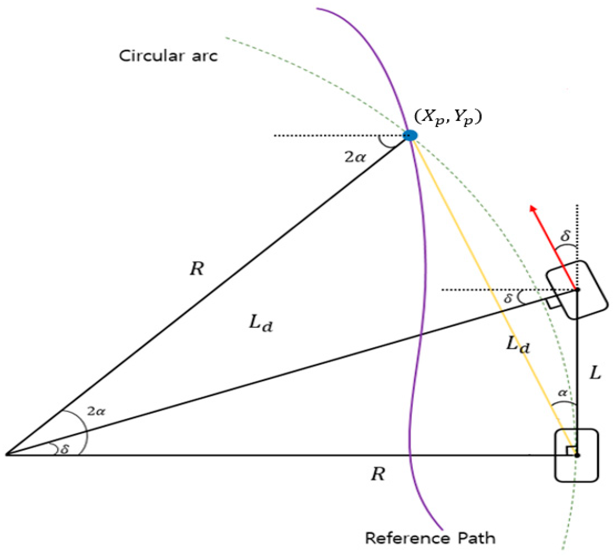
2.3.2. Path Tracking

Path tracking involves controlling an autonomous vehicle along a predefined reference path by minimizing positional and heading errors. The path-tracking algorithm for the autonomous forwarder computes the steering angle based on the current vehicle speed, position, and heading, and enables it to autonomously follow the reference path. In this study, the geometric pure pursuit algorithm was applied for path tracking. Pure pursuit, alongside the follow-the-carrot method, is one of the most popular path-tracking algorithms. It calculates the steering angle by fitting an arc between the current vehicle center and target points, using the curvature of arc to determine the required steering angle [23,24]. The reference path is defined as a series of waypoints, with the algorithm continuously adjusting the vehicle steering direction and speed based on the positional and heading coordinates of both the vehicle and target point. The conventional pure pursuit algorithm, designed for wheeled vehicles, calculates the steering angle using the curvature of the arc between the rear-wheel center and the target point (Figure 9). However, tracked vehicles differ from wheeled vehicles in that they lack steering-angle limits and wheelbase constraints. To adapt the pure pursuit algorithm for tracked vehicles, a modified geometric model was developed, as shown in Figure 10. Using the vehicle center coordinates ( X p , Y p ) and the target point ( X L , Y L ), and determined by the look-ahead distance (LAD), Equations (1)–(3) were derived to calculate the platform steering angle while accounting for the unique characteristics of tracked vehicles.
tan α = X Y
α = tan 1 X Y
θ = δ α
where X = x-axis distance between forwarder center coordinates and target points. Y = y-axis distance between forwarder center coordinates and target points.
δ = Forwarder   steering   angle
θ = Forwarder   direction   angle

2.3.3. Driving Error Correction and Emergency Stop

The autonomous forwarder uses safety algorithms to ensure reliable operation even in challenging GNSS environments. If the GNSS/INS system detects weak satellite signals or unreliable RTK correction signals, it autonomously initiates an emergency stop to avoid unsafe driving. In addition, the system uses a filtering process to improve position accuracy. If the position data suddenly change significantly due to GNSS signal instability, these values are excluded from the input of the path tracking algorithm. This method minimizes the risk of trajectory deviation due to inaccurate position information. Finally, if the forwarder steering angle and forwarder heading angle calculated from the path tracking deviate significantly by more than 5 degrees, assuming that the GNSS and INS corrections are lost, then an emergency stop is engaged.

2.4. Performance Test of the Autonomous Forwarder

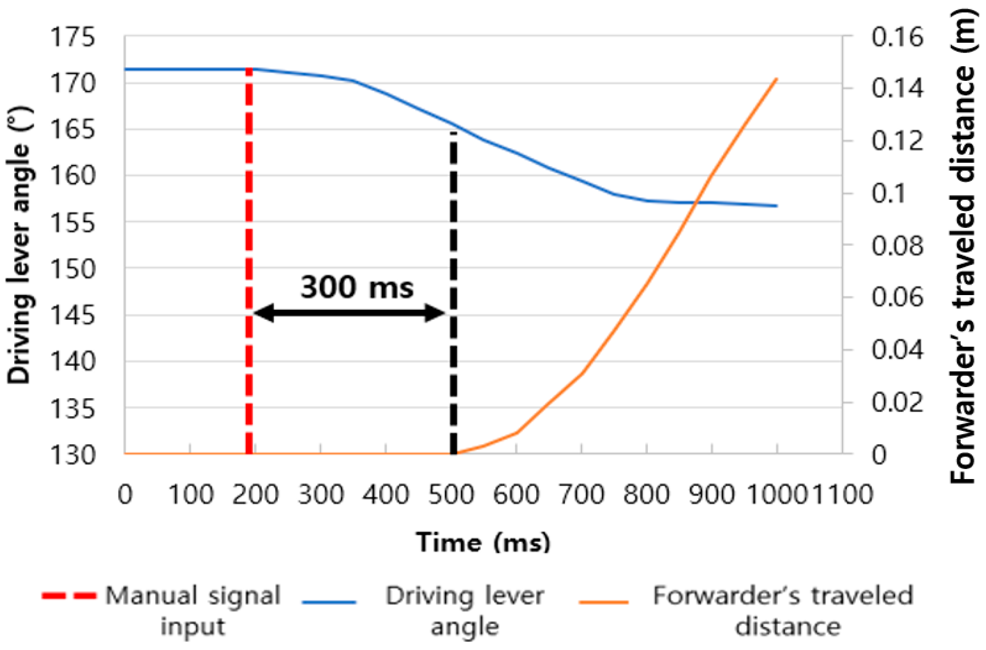
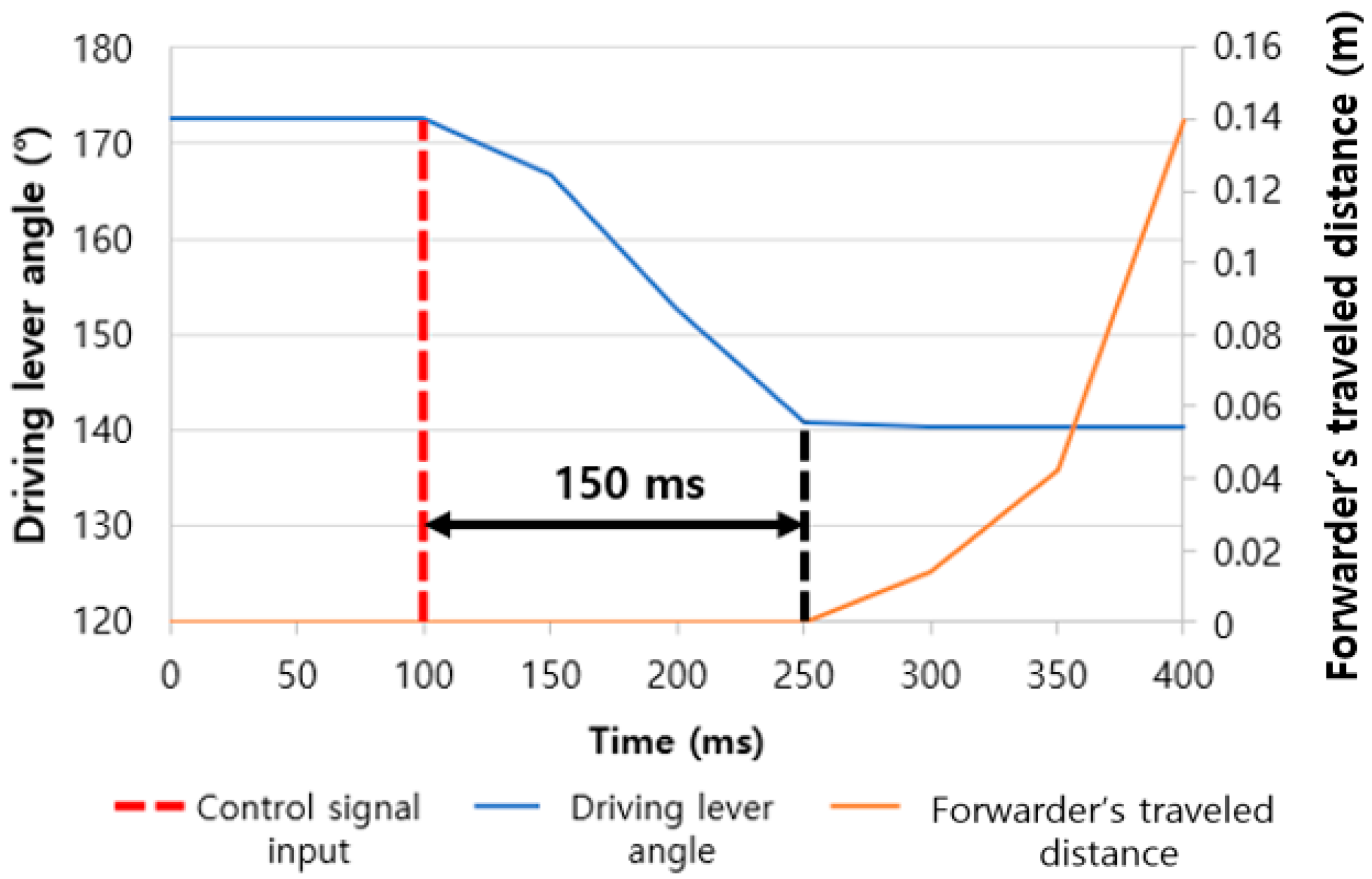
2.4.1. Steering Control Performance Test

Accurate and rapid steering control is crucial for the autonomous operation of a forwarder, requiring precise and swift positional adjustments of the driving levers. The autonomous driving system developed in this study regulates the forwarder steering and speed by controlling the driving lever angles with servo motors. To assess the performance of the driving lever control system, a comparison was conducted between manual operation by a human operator and the automated control system. Encoders attached to the drive motors and embedded in the servo motors were used to simultaneously measure the forwarder’s traveled distance and driving lever angles. Owing to the mechanical operation system and hydraulic motor characteristics, a delay occurs between the application of control signals and the rotation of the drive motor, leading to an increase in forwarder’s traveled distance (Figure 11). The shorter the delay between shifting the driving lever from neutral to the forward and the moment the distance driven starts to increase, the better the steering control performance.

2.4.2. Driving Test

In total, three autonomous driving tests were run on different days over the forest road at the experimental site. Travelling at the speed of 7–8 km/h, the actual position data of forwarder were acquired using instrumentation GNSS/INS.

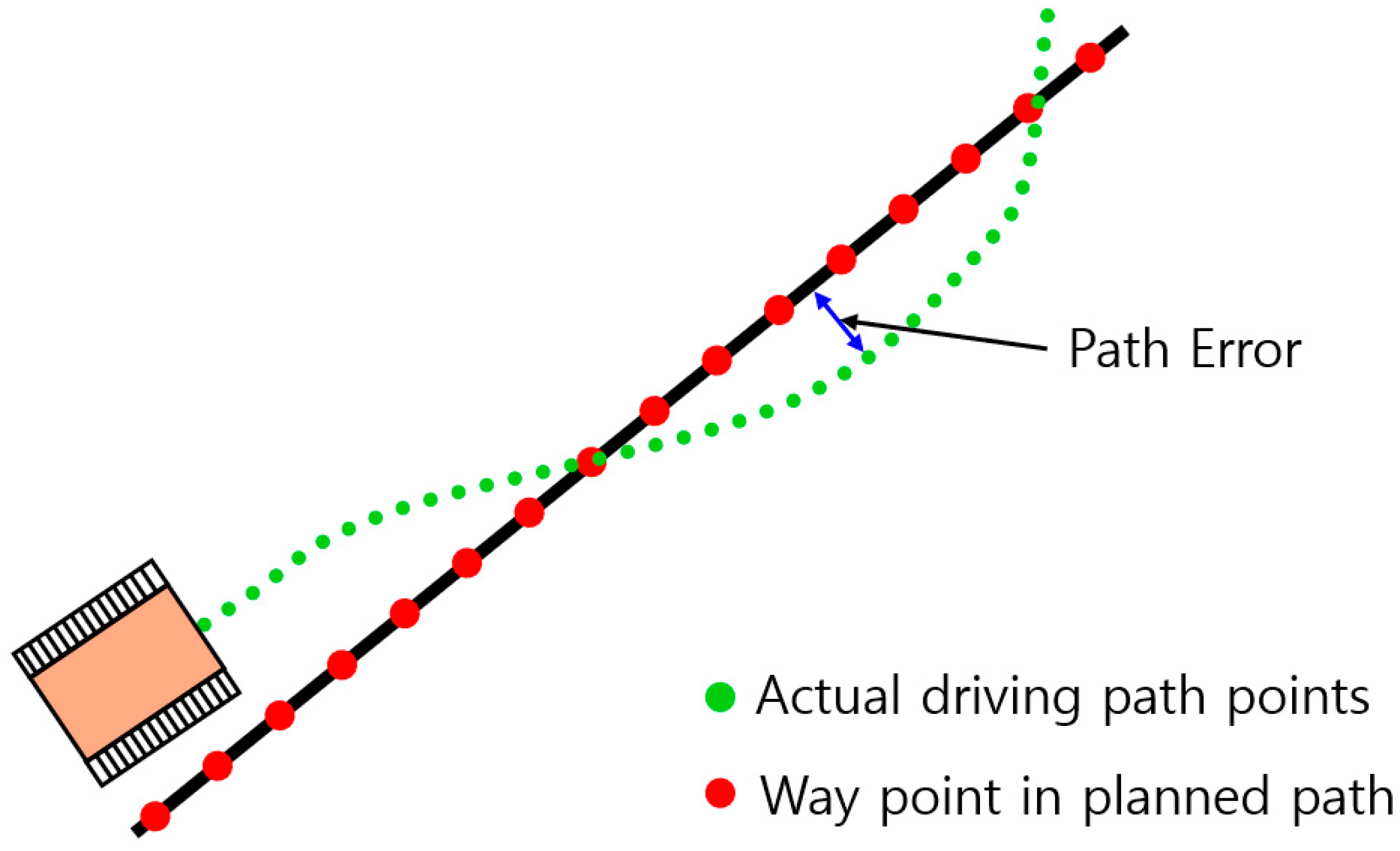
2.4.3. Autonomous Driving Error Calculation

The positional errors between the actual driving path and the input reference path were calculated to determine the path-tracking performance. For error measurement, the input driving path points used for autonomous driving were converted into a series of straight-line segments. The minimum distances were then obtained by comparing the actual driving path points with the corresponding straight-line equations, as illustrated in Figure 12. The root mean square error (RMSE) of the path error was calculated using Equation (4). As shown in Figure 13, the actual driving path was measured using a high-performance GNSS/INS system (PwrPak7D, Novatel, Calgary, Canada) for driving path measurement, with the specifications detailed in Table 7, which was different from the GNSS/INS system used for autonomous driving. A lateral offset was applied to align the measurements with the same positional coordinates used for autonomous driving, with the system configured to automatically save data during autonomous operation.
R M S E = ( P a t h   E r r o r ) 2 N u m b e r   o f   d a t a

3. Results

3.1. Steering Control Performance Evaluation

Accurate and rapid steering control, essential for the autonomous driving of a forwarder, relies on precise and swift positional control of the driving levers. The autonomous system developed in this study controlled the forwarder steering and speed by adjusting the driving lever angles through servo motors. To evaluate its performance, a comparison was made between manual operation by a human operator and the servo-motor-based automated control system. Owing to the inherent characteristics of mechanical control and hydraulic motors, a delay occurs between the application of control signals and the instant at which the drive motor rotates, causing the vehicle to begin moving. As shown in Figure 14, a shorter delay between moving the driving lever from the neutral position (172°) to the forward position and the onset of vehicle movement indicates faster steering control responses. The servo motor control system demonstrated a response speed over 150 ms faster than manual operation (Figure 15). This improvement is attributed to the servo motor ability to adjust the driving levers more rapidly than human operation. Therefore, it can be inferred that the driving lever control system developed in this study provides the necessary steering accuracy and rapidity along with the speed control required for autonomous driving.

3.2. Autonomous Path-Generation Results

The autonomous driving path used in this study was obtained from a 1.5 km section of forest road near Jikdong-ri, Soheul-eup, Pocheon, Gyeonggi-do, South Korea (127°10′31.687″ E, 37°45′45.975″ N). A skilled operator drove the forwarder along a forest road to record the path with high positional accuracy. As shown in Figure 16, a 1.5 km driving path was generated and post-processed using the Novatel Inertial Explorer GNSS + INS software. As shown in Figure 16, the post-processed path (planned path) was compared with three repeated driving paths along the forest road, which yielded a maximum error of 10 cm. Despite GNSS positional errors caused by the surrounding terrain and canopy, the planned path consistently converged within the boundaries of the three repeated paths, demonstrating its sufficient accuracy for autonomous driving applications.

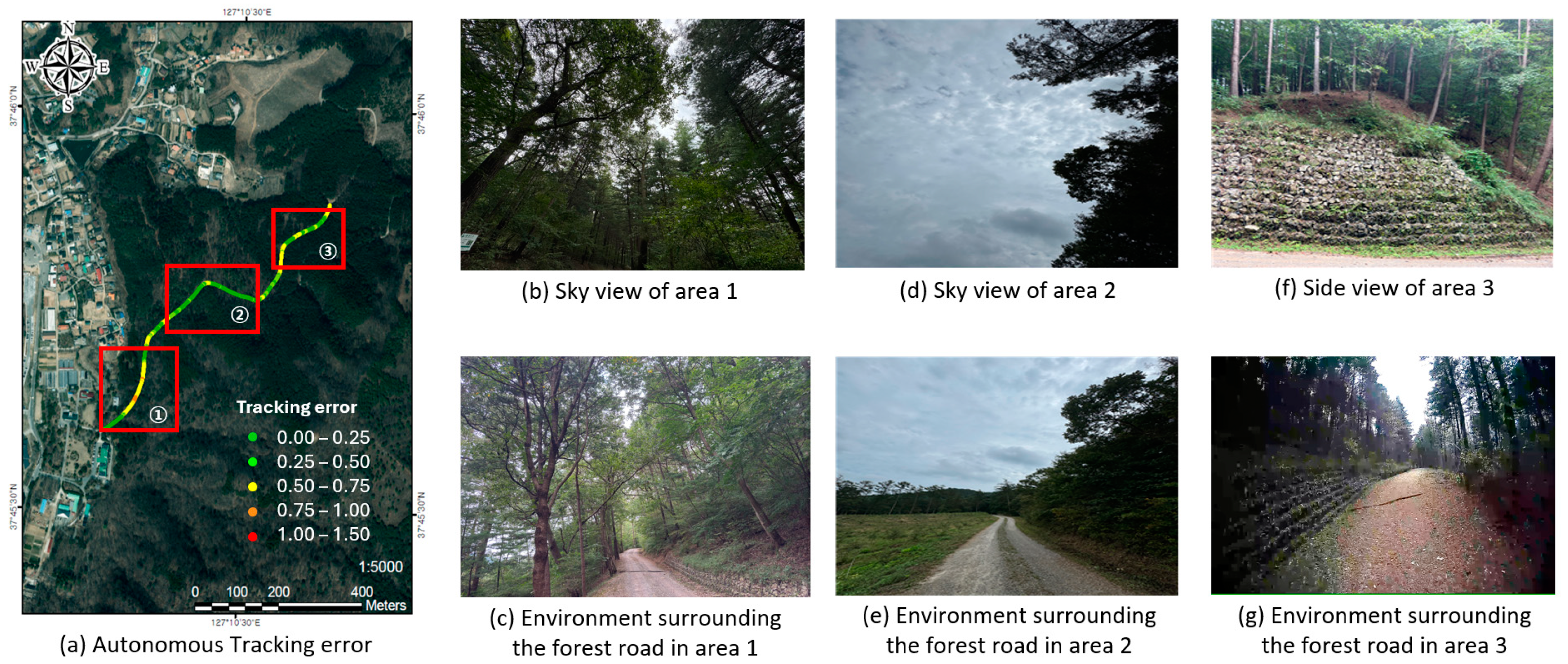
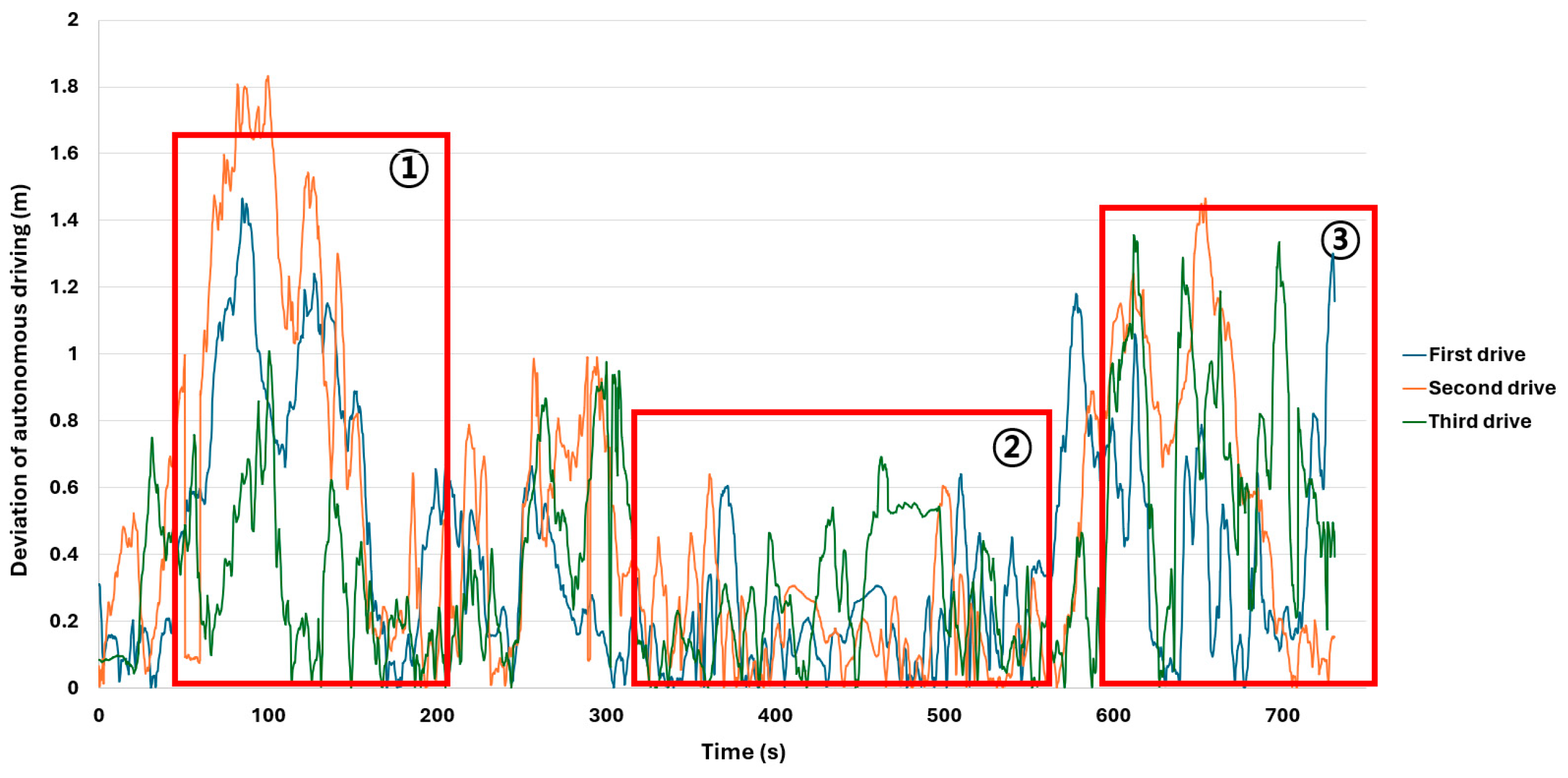
3.3. Autonomous Driving Path Error Results

In this study, the autonomous forwarder followed a pre-generated autonomous driving path. As presented in Table 8, path tracking errors were evaluated over three repeated autonomous driving trials. The RMSE ranged from a minimum of 0.389 m to a maximum of 0.395 m, with all RMSEs remaining under the threshold of 0.4 m. The maximum deviations are also presented because they indicate the extent to which the forwarder may deviate from its planned path and enter a dangerous situation. This was observed to be the largest in Figure 17a(①), where a dense canopy exists. The tree canopy is believed to have had a considerable shielding effect, preventing the GNSS receiver from properly receiving satellite signals. Near the artificial structures beside the forest road in Figure 17a(③), the maximum deviation was not small. Such obstacles may have caused multipath effects in receiving the GNSS signal, leading to positioning errors and consequently resulting in path-tracking error. Contrary to previous two trial tests, in the third test, the maximum deviation in Figure 17a(①) was measured to be relatively small. This is likely due to the fact that the three tests were conducted on different days, leading to variations in satellite orbit errors and ionospheric and tropospheric delays, which may have contributed to reduced positioning errors in that particular test. As shown in the red-highlighted boxes in Figure 17, most errors were concentrated in specific regions where GNSS signal reception was hindered by external factors such as dense tree canopies and uneven terrain, leading to inaccuracies in the forwarder positional estimation. The majority of path errors occurred in areas with high canopy density (Figure 17a(①)–c), where dense tree coverage obstructed GNSS signals. Conversely, in open areas where the GNSS receiver can observe the sky without any obstacles blocking it, the error was smaller than in other sections (Figure 17a(②),d,e). Significant positional errors were also observed in areas with landslide prevention structure located higher than the GNSS antenna and high embankments near the autonomous driving path (Figure 17a(③),f,g). Figure 18 is a graph showing the path errors that occurred in various sections of the autonomous driving path. In sections with dense trees (Figure 18(①)) and locations where landslide prevention structures were installed (Figure 18(③)), the path errors tended to increase. However, in sections like that shown in Figure 18(②), where GNSS reception was smooth, the path errors were low. The trajectories of forwarder movement in the three repeats of the test showed similar patterns in the aspect of path errors. This was analyzed to be due to environmental factors that limited GNSS signal reception. These findings underscore that the autonomous driving path errors were strongly influenced by environmental factors, such as tree density, canopy cover, and the topographical features of the surrounding terrain.

4. Discussion and Conclusions

This study developed an autonomous driving system for tracked forwarders using a GNSS/INS-based approach system consisting of three major components: a driving lever control system, an RTK-GNSS-based inertial navigation device, and path-planning and -tracking algorithms. The mechanical control system of the existing forwarder was replaced with an electronic one, and path-planning and -tracking algorithms were implemented. The electronic control system, utilizing servo motors to operate the steering levers, exhibited faster and more accurate steering control than the manual system operated by human drivers. The electronic control system developed in this study is designed for a tracked forwarder with lever-based steering, but its applicability to other machine chassis, such as a wheeled forwarder with articulated steering, requires further investigation. To apply the system to wheeled machines, the control algorithm must be modified to account for various kinematic constraints and steering mechanisms.
The autonomous driving path was generated by recording the trajectory of a skilled operator driving along a forest road. The collected data were post-processed using the Novatel Inertial Explorer GNSS + INS software to minimize GNSS errors. This post-processing approach, which fused GNSS and inertial data, significantly reduced GNSS errors and maximized satellite signal availability, even under weak signal conditions.
The tracked autonomous driving system encountered errors due to various environmental conditions, with GNSS positional errors exerting the most significant impact. Abdi et al. [25] identified tree height, ground elevation, direction, canopy cover, and tree density as the primary factors influencing GNSS position accuracy in forest environments. Matsuzaki [26] attempted to enhance GNSS accuracy by modifying the antenna type and height but observed no significant improvement in positional precision. Conversely, integrating inertial measurement unit data with multi-GNSS systems helped in obtaining more precise satellite signals and improving location accuracy [27,28]. Drawing on these findings, this study used a GNSS/INS system capable of receiving multi-GNSS signals, which effectively minimized autonomous driving errors. However, significant positional errors persisted in areas with dense canopy cover and complex terrain features.
The autonomous driving test conducted on the forest road path generated from the post-processed data was tracked using a pure tracking algorithm, and the RMSE was achieved between 0.389 m and 0.395 m. However, sometimes, a maximum deviation of more than 1 m occurred due to the forest road environment, while the maximum error was 0.05 m in areas with good GNSS reception. Nevertheless, autonomous driving was completed without driver intervention through driving error correction. The primary source of path errors was GNSS positional inaccuracies, which were most significant in areas with dense canopies and landslide prevention structure located higher than the GNSS antenna obstructing GNSS signals. These findings underscore the importance and feasibility of deploying autonomous forwarders in diverse forest environments and lay a critical foundation for advancing autonomous forestry machinery. In addition, it is necessary to quantitatively identify the effect of tree canopies on GNSS reception performance and establish criteria for assessing the feasibility of GNSS application in autonomous driving within the given area.
Future research should focus on addressing the limitations of GNSS/INS systems by exploring sensor fusion techniques that integrate image sensors and LiDAR to mitigate positional inaccuracies in challenging environmental conditions. This study provides a robust technological basis for the development of autonomous forestry machinery, contributing to sustainable forest management and improving the efficiency of forestry operations.

Author Contributions

Conceptualization, J.-H.O. and H.-S.L.; methodology, H.-S.L.; software, H.-S.L.; validation, B.-S.S. and J.-H.O.; investigation, G.-H.K. and H.-S.J.; resources, H.-S.L. and H.-S.M.; data curation, H.-S.L.; writing original draft preparation, H.-S.L.; writing—review and editing, J.-H.O. and B.-S.S.; visualization, H.-S.L. All authors have read and agreed to the published version of the manuscript.

Funding

This study was conducted with the support of the R&D Program for Forest Science Technology [grant number 2023475A00-2325-BB01] provided by the Korea Forest Service (Korea Forestry Promotion Institute).

Data Availability Statement

Please contact the corresponding author for data requests.

Conflicts of Interest

The authors declare no conflicts of interest.

Abbreviations

The following abbreviations are used in this manuscript:
GNSS Global Navigation Satellite System
HSThydrostatic transmission
INSInertial Navigation System
IPinternet protocol
LAD look-ahead distance
LiDARlight detection and ranging
NTRIPnetworked transport of RTCM via IP
RTKreal-time kinematics
RMSEroot mean square error
RTCMRadio Technical Commission for Maritime Services
SLAMsimultaneous localization and mapping

References

  1. Marchi, E.; Chung, W.; Visser, R.; Abbas, D.; Nordfjell, T.; Mederski, P.S.; McEwan, A.; Brink, M.; Laschi, A. Sustainable Forest Operations (SFO): A New Paradigm in a Changing World and Climate. Sci. Total Environ. 2018, 634, 1385–1397. [Google Scholar] [CrossRef] [PubMed]
  2. Eom, C.-D.; Kim, M.-J.; Lee, C.-G. Analysis of Domestic Wood Resources Applicable for Wood Urbanism. In Proceedings of the 2021 Proceedings of Vitrtual Annual Korean Wood Science and Technology Conference, Online, 23–24 April 2021; p. 99. [Google Scholar]
  3. Kim, H.-Y.; Park, S.-H.; Lee, S.-H.; Park, C.-M. Analysis on Safety Accident Characteristics of Forestry Workers in Korea. J. Korean For. Soc. 2013, 102, 550–559. [Google Scholar] [CrossRef]
  4. Treanor, J.; Hartley, A.; Harvey, G.; May, B.; Bell, T. Design of a Prototype Autonomous Forestry Extraction Machine. Available online: https://ir.canterbury.ac.nz/items/5bf86030-c184-4067-a9d3-26262754e4f5.html (accessed on 23 January 2025).
  5. Bentley, T.A.; Parker, R.J.; Ashby, L. Understanding Felling Safety in the New Zealand Forest Industry. Appl. Ergon. 2005, 36, 165–175. [Google Scholar] [CrossRef] [PubMed]
  6. Cho, M.J.; Choi, Y.S.; Lee, E. Identifying Risk Factors and Evaluating Occupational Safety in South Korean Forestry Sector. Forests 2023, 14, 851. [Google Scholar] [CrossRef]
  7. Lundbäck, M. Roadmap for Teleoperation and Automation of Forwarding. Ph.D. Thesis, Umeå University, Umeå, Sweden, 2022. [Google Scholar]
  8. Müller, F.; Jaeger, D.; Hanewinkel, M. Digitization in Wood Supply—A Review on How Industry 4.0 Will Change the Forest Value Chain. Comput. Electron. Agric. 2019, 162, 206–218. [Google Scholar] [CrossRef]
  9. Han, J.H.; Park, C.H.; Kwon, J.H.; Lee, J.; Kim, T.S.; Jang, Y.Y. Performance Evaluation of Autonomous Driving Control Algorithm for a Crawler-Type Agricultural Vehicle Based on Low-Cost Multi-Sensor Fusion Positioning. Appl. Sci. 2020, 10, 4667. [Google Scholar] [CrossRef]
  10. Li, M.; Imou, K.; Wakabayashi, K.; Yokoyama, S. Review of Research on Agricultural Vehicle Autonomous Guidance. Int. J. Agric. Biol. Eng. 2009, 2, 1–16. [Google Scholar] [CrossRef]
  11. Kim, H.; Gong, S.; Rhee, J.; Lim, J.-G.; Kim, W.-S. Technological Trends of Intelligent Agricultural Machinery. J. Drive Control 2023, 20, 80–91. [Google Scholar] [CrossRef]
  12. Katupitiya, J.; Eaton, R. Precision Autonomous Guidance of Agricultural Vehicles for Future Autonomous Farming. In Proceedings of the American Society of Agricultural and Biological Engineers Annual International Meeting 2008, Providence, RI, USA, 29 June–2 July 2008; ASABE 2008. Volume 10, pp. 1–6. [Google Scholar] [CrossRef]
  13. Leidenfrost, H.T.; Tate, T.T.; Canning, J.R.; Anderson, M.J.; Soule, T.; Edwards, D.B.; Frenzel, J.F. Autonomous Navigation of Forest Trails by an Industrial-Size Robot. Trans. ASABE 2013, 56, 1273–1290. [Google Scholar] [CrossRef]
  14. Krulikowski Rodrigues, C.; da Silva Lopes, E.; Figueiredo Filho, A.; Kaminski Cândido da Silva, M. Modeling Of Forwarder Productivity and Costs in Thinned Pine Stands. Floresta 2017, 48, 285–292. [Google Scholar] [CrossRef]
  15. Ringdahl, O. Automation in Forestry Development of Unmanned Forwarders. Ph.D. Thesis, Umeå University, Umeå, Sweden, 2011. [Google Scholar]
  16. Choi, Y.-S.; Cho, M.-J.; Mun, H.-S.; Kim, D.-H.; Cha, D.-S.; Han, S.-K.; Oh, J.-H. Analysis on Yarding Productivity and Cost of Tower-Yarder Based on Excavator Using Radio-Controlled Double Clamp Carriage. J. Korean For. Soc. 2018, 107, 266–277. [Google Scholar] [CrossRef]
  17. Hibiya, R. LiDAR-Based Accessibility Mapping of Forest Operation Machines in Steep Terrain. Master’s Thesis, University of Eastern Finland, Kuopio, Finland, 2021. [Google Scholar]
  18. Visser, R.; Obi, O.F. Automation and Robotics in Forest Harvesting Operations. Croat. J. For. Eng. 2021, 42, 13–24. [Google Scholar] [CrossRef]
  19. Pereira, T.; Gameiro, T.; Viegas, C.; Santos, V.; Ferreira, N. Sensor Integration in a Forestry Machine. Sensors 2023, 23, 9853. [Google Scholar] [CrossRef] [PubMed]
  20. La Hera, P.; Mendoza-Trejo, O.; Lindroos, O.; Lideskog, H.; Lindbäck, T.; Latif, S.; Li, S.; Karlberg, M. Exploring the Feasibility of Autonomous Forestry Operations: Results from the First Experimental Unmanned Machine. J. Field Robot. 2024, 41, 942–965. [Google Scholar] [CrossRef]
  21. Nakagomi, H.; Fuse, Y.; Nagata, Y.; Hosaka, H.; Miyamoto, H.; Yokozuka, M.; Kamimura, A.; Watanabe, H.; Tanzawa, T.; Kotani, S. Forest Road Surface Detection Using LiDAR-SLAM and U-Net. In Proceedings of the 2021 IEEE/SICE International Symposium on System Integration, Iwaki, Japan, 11–14 January 2021; pp. 727–732. [Google Scholar]
  22. Seo, I.; Seo, D.; Kim, K. Development of Working Path Formation Program for Autonomous Tractor System. J. Agric. Sci. 2010, 37, 113–121. [Google Scholar]
  23. Hellström, T.; Ringdahl, O. Follow the Past: A Path-Tracking Algorithm for Autonomous Vehicles. Int. J. Veh. Auton. Syst. 2006, 4, 216–224. [Google Scholar] [CrossRef]
  24. Coulter, R.C. Implementation of the Pure Pursuit Path Tracking; Technical Report; Robotics Institute, Carnegie Mellon University: Pittsburgh, PA, USA, 1992. [Google Scholar]
  25. Abdi, O.; Uusitalo, J.; Pietarinen, J.; Lajunen, A. Evaluation of Forest Features Determining GNSS Positioning Accuracy of a Novel Low-Cost, Mobile RTK System Using LiDAR and TreeNet. Remote Sens. 2022, 14, 2856. [Google Scholar] [CrossRef]
  26. Matsuzaki, Y.; Kondo, Y.; Kishi, Y.; Esumi, J.; Yoshimura, T. Accuracy Assessment of Real-Time Kinematic Using a Low-Cost Dual-Frequency GNSS Receiver in a Sugi (Cryptomeria Japonica) Plantation Forest. J. Jpn. For. Eng. Soc. 2022, 37, 183–192. [Google Scholar] [CrossRef]
  27. Andreas, H.; Zainal Abidin, H.; Anggreni Sarsito, D.; Pradipta, D. Study the Capabilities of RTK Multi GNSS under Forest Canopy in Regions of Indonesia. In Proceedings of the E3S Web of Conferences, St. Petersburg, Russia, 19–20 November 2019; EDP Sciences: Les Ulis, France, 2019; Volume 94. [Google Scholar] [CrossRef]
  28. Kaartinen, H.; Hyyppä, J.; Vastaranta, M.; Kukko, A.; Jaakkola, A.; Yu, X.; Pyörälä, J.; Liang, X.; Liu, J.; Wang, Y.; et al. Accuracy of Kinematic Positioning Using Global Satellite Navigation Systems under Forest Canopies. Forests 2015, 6, 3218–3236. [Google Scholar] [CrossRef]
Figure 1. Location of study site.
Forests 16 00647 g001
Figure 2. Sensors and control system adapted to the autonomous forwarder.
Forests 16 00647 g002
Figure 3. Power and signal lines for control of the autonomous forwarder.
Forests 16 00647 g003
Figure 4. MST 800VDL forwarder used in the study.
Forests 16 00647 g004
Figure 5. Configuration of main controller and RTK-GNSS/INS system with dual antennas.
Forests 16 00647 g005
Figure 6. Driving and steering control lever.
Forests 16 00647 g006
Figure 7. Range of motion and torque measurement of the steering control lever.
Forests 16 00647 g007
Figure 8. Components and assembly of servo-motor-actuated driving lever.
Forests 16 00647 g008
Figure 9. Pure pursuit geometric model of the forwarder.
Forests 16 00647 g009
Figure 10. Adapted pure pursuit model for a tracked forwarder, incorporating the look-ahead distance (LAD).
Forests 16 00647 g010
Figure 11. Correlation between driving lever angle and forwarder’s traveled distance.
Forests 16 00647 g011
Figure 12. Definition of autonomous driving error.
Forests 16 00647 g012
Figure 13. Installed view of additional GNSS/INS with higher accuracy to measure the travelled path of the forwarder.
Forests 16 00647 g013
Figure 14. Manual driving lever input and forwarder’s traveled distance.
Forests 16 00647 g014
Figure 15. Servo motor driving lever input and forwarder’s traveled distance.
Forests 16 00647 g015
Figure 16. Comparison of repeated paths and planned paths.
Forests 16 00647 g016
Figure 17. Autonomous driving error according to the surrounding environment of the forest road.
Forests 16 00647 g017
Figure 18. Changes in deviation by autonomous driving section.
Forests 16 00647 g018
Table 1. Characteristics of the study site.
ClassificationSpecification
Slope (°)15–20
Elevation (m)110–170
Tree speciesPinus koraiensis, Pinus rigida, Larix kaempferi
Stand typeArtificial forest
Site   volume   ( m 3 / h a ) 381
Height (m)20–25
Table 2. Specifications of the tracked forwarder used in the study.
ItemsSpecification
EngineTypeWater-cooled
4-cycle direct injection
with turbocharger
Rated Power/RPM114HP/2800
Displacement3910 cc
TransmissionTypeHST
Max Hydraulic Pressure335 kg/cm2
BrakeTypeHydraulic actuated mechanical brake
Operating WeightWeight of machine6400 kg
Max payload4300 kg
DimensionsFull length5416 mm
Full width2300 mm
Wheelbase3130 mm
Climbing angleMaximum climbing angle30°
Table 3. Antenna specifications.
ItemsSpecification
FrequencyL1, L2, G1, G2, B1, B2, E1, E5b, QZSS, SBAS
Peak gain5 dBi
Azimuth coverage360°
IP ratingIP66
Table 4. NTRIP specifications.
ItemsSpecification
Power supply3.0–3.6 V
WiFi protocols802.11 b/g/n
Peripheral busUART/SPI/I2C
Network protocolsIPv4, TCP/UDP/HTTP/FTP
Central processing unit clock speed160 MHz
ProcessorXtensa Dual-core 32-bit LX6 microprocessor
Table 5. Specifications of GNSS/INS used in the autonomous driving control.
ItemsSpecification
Primary RFL1, L2, E1, E5b, B1, B2
Secondary RFL1, L2, E1, E5b, B1, B2
Position accuracySingle1.5 m
RTK1 cm + 1 ppm
Yaw accuracy0.5°
Velocity accuracy0.04 m/s
INS positioning error0.3 m
Output interfaces3 UART
1 USB 2.0
2 SPI
1 CAN bus
Table 6. Specifications of the servo motor used in the study.
ItemsSpecification
Motor typeBLDC
Gear typeMetal
PotentiometerMagnetic encoder
Operating voltage18–32 V
Stall current10 A
Max Speed0.19 s/60°
Stall torque14.42 N·m at 12 V
ProtocolCAN, DroneCAN, UAVCAN
IP ratingIP68
Table 7. Specifications of GNSS/INS for instrumentation.
ItemsSpecification
Primary RFL1 C/A, L1C, L2C, L2P, L5, L2 C/A, L2P, L3, L5, B1l, B1C, B2a, B2b, B2l, E1, E5, AltBOC, E5a, E5b
Secondary RFL1 C/A, L1C, L2C, L2P, L5, L2 C/A, L2P, L3, L5, B1l, B1C, B2a, B2b, B2l, E1, E5, AltBOC, E5a, E5b
Position accuracySingle L1/L21.3 m
RTK1 cm + 1 ppm
Heading accuracy (base line 2 m)0.08°
Velocity accuracy0.03 m/s
Output interfaces3 UART
1 Wi-Fi
2 USB
1 CAN bus
1 Ethernet
Table 8. Autonomous driving error.
Test RunMax. Deviation (m)Std. Deviation(m)RMSE (m)
Area ①Area ②Area ③Area ①Area ②Area ③
First1.4650.7241.3000.4240.1510.3310.389
Second1.8320.7541.4650.5810.1550.4120.395
Third1.0080.9761.3550.2210.2070.3540.393
Disclaimer/Publisher’s Note: The statements, opinions and data contained in all publications are solely those of the individual author(s) and contributor(s) and not of MDPI and/or the editor(s). MDPI and/or the editor(s) disclaim responsibility for any injury to people or property resulting from any ideas, methods, instructions or products referred to in the content.

