
Withdrawal Behavior of the Self-Tapping Screws in Bamboo/Wood-Oriented Strand Board

Abstract
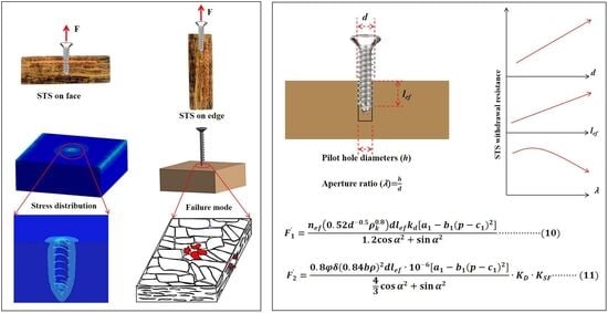
1. Introduction
2. Materials and Methods
2.1. Materials
2.2. Tests for Materials Properties
2.3. Tests for Screw Withdrawal
3. Results and Discussion
3.1. Properties of Materials
3.2. Withdrawal Resistance
3.2.1. Effects of Penetration Length on Withdrawal Resistance
3.2.2. Effect of Aperture Ratio on Withdrawal Resistance
3.2.3. Effects of STS Diameter on Withdrawal Resistance
3.3. Theoretical Calculation of Withdrawal Resistance
3.3.1. Existing Calculation Formulas
3.3.2. Calculation of the Withdrawal Resistance of STS in OSB
4. Conclusions
Author Contributions
Funding
Data Availability Statement
Acknowledgments
Conflicts of Interest
Abbreviations
| OSB | Oriented strand board |
| WOSB | Wood-oriented strand board |
| BOSB | Bamboo-oriented strand board |
| STS | Self-tapping screw |
References
- Kask, R.; Lille, H.; Kiviste, M.; Tamm, R.; Reigo, V.; Lne, J.O. Evaluation of some mechanical and physical properties of ‘Oriented Strand Board (OSB/3)’ following cyclic accelerated aging tests. Wood Mater. Sci. Eng. 2021, 10, 358–365. [Google Scholar] [CrossRef]
- Zhang, K.; Zhang, J.; Guo, Y.; Chen, Y. Study on Joint Model Simplification for Finite Element Analysis of Bamboo/Wood-Oriented Strand Board Furniture. Materials 2024, 17, 4395. [Google Scholar] [CrossRef]
- Sun, Y.H.; Jiang, Z.H.; Zhang, X.B.; Sun, Z.J.; Liu, H.R. Behavior of glued laminated bamboo and bamboo-oriented strand board sheathing-to-framing connections. Eur. J. Wood Wood Prod. 2019, 77, 1189–1199. [Google Scholar] [CrossRef]
- Sun, Y.H.; Gong, J.Y.; Liu, H.R.; Fang, C.H. Axial Compression Behaviors of Columns Fabricated from Bamboo Oriented Strand Boards. Forests 2022, 13, 1817. [Google Scholar] [CrossRef]
- Sharma, B.A.G.R.; Michael, H. Effect of processing methods on the mechanical properties of engineered bamboo. Constr. Build. Mater. 2015, 83, 95–101. [Google Scholar] [CrossRef]
- Zhang, K.; Wang, F.; Xu, R.; Fan, X.; Yan, B.; Li, C.; Liu, S.; Guo, Y.; Chen, Y. Experimental and numerical study on the screw connection strength of bamboo-oriented strand board compared with wood-oriented strand board. J. Wood Sci. 2021, 67, 69. [Google Scholar] [CrossRef]
- Pour, M.F.; Hatefnia, H.; Dorieh, A.; Kiamahalleh, M.V.; Afrouzi, Y.M. Research on Medium density fiberboard (MDF) behavior against screw axial withdrawal: Impact of density and operational variables. Structures 2022, 39, 194–206. [Google Scholar] [CrossRef]
- Guo, Y.; Zhu, S.; Chen, Y. Contrastive analysis of screw withdrawal resistance between bamboo oriented strand board and conventional particleboard. Wood Res. 2018, 63, 1071–1080. [Google Scholar]
- Li, H.; Qiu, H.; Wang, Z.; Lu, Y. Withdrawal resistance of the self-tapping screws in engineered bamboo scrimber. Constr. Build. Mater. 2021, 311, 125315. [Google Scholar] [CrossRef]
- Li, H.; Lam, F.; Qiu, H. Flexural performance of spliced beam connected and reinforced with self-tapping wood screws. Eng. Struct. 2017, 152, 523–534. [Google Scholar] [CrossRef]
- Li, H.; Wang, P.; Zhao, Q.; Ou, J.; Liu, J.; Wang, Z.; Qiu, H.; Zuo, T. Experimental and numerical study on timber-to-bamboo scrimber connection with self-tapping screws. Constr. Build. Mater. 2024, 411, 134225. [Google Scholar] [CrossRef]
- Wang, M.; Zhao, Y.; Xu, Q.; Harries, K.A.; Li, X.; Leng, Y. Experimental research on wood beams strengthened with engineered bamboo laminates attached with self-tapping screws. J. Build. Eng. 2022, 53, 104560. [Google Scholar] [CrossRef]
- Miljković, J.; Popović, M.; Điporović-Momčilović, M.; Gavrilović-Grmuša, I. Edge screw withdrawal resistance in conventional particleboard and OSB: Influence of the particles type. Glas. Sumar. Fak. 2007, 95, 109–117. [Google Scholar] [CrossRef]
- Erdil, Y.Z.; Zhang, J.; Eckelman, C.A. Holding strength of screws in plywood and oriented strandboard (Wood Engineering). For. Prod. J. 2002, 56, 55–62. [Google Scholar]
- Wang, X.A.; Salenikovich, A.; Mohammad, M. Localized density effects on fastener holding capacities in wood-based panels. For. Prod. J. 2007, 57, 103–109. [Google Scholar]
- Yorur, H. Utilization of waste polyethylene and its effects on physical and mechanicalproperties of oriented strand board. BioResources 2016, 11, 2483–2491. [Google Scholar] [CrossRef]
- Chui, Y.H.; Craft, S. Fastener head pull-through resistance of plywood and oriented strand board. Can. J. Civ. Eng. 2011, 29, 384–388. [Google Scholar] [CrossRef]
- Maulana, S.; Hidayat, W.; Sumardi, I.; Wistara, N.J.; Maulana, M.I.; Kim, J.H.; Lee, S.H.; Kim, N.H.; Febrianto, F. Properties of Dual-species Bamboo-Oriented Strand Boards Bonded with Phenol Formaldehyde Adhesive under Various Compression Ratios. Bioresources 2021, 16, 5422–5435. [Google Scholar] [CrossRef]
- Li, G.H.; Zhang, J.; Zhang, W.F.; Wang, H.Y.; Lu, T.H.; Yuan, S.F.; Wang, X.Z. The effects of orientation angle of bamboo strands on the properties of bamboo oriented strand board. J. Build. Eng. 2024, 98, 111476. [Google Scholar] [CrossRef]
- Sun, Y.H.; Jiang, Z.H.; Liu, H.R.; Sun, Z.J.; Fang, C.H. The bending properties of bamboo strand board I-beams. J. Wood Sci. 2019, 65, 50. [Google Scholar] [CrossRef]
- Xu, R.; Zhang, K.; Ren, L.; Wang, F.; Zhu, Z.; Zhang, T.; Liu, S.; Fang, Y.; Guo, Y.; Chen, Y. Connection Performance Examination of a New Bamboo-Oriented Strand Board Connector. Bioresources 2021, 16, 2906–2920. [Google Scholar] [CrossRef]
- Zhang, E.; Chen, G.; Zhu, W.; Wang, C.; Yang, W. Experimental investigation on withdrawal resistance performance of nails in southern pine. Eng. Struct. 2024, 306, 117755. [Google Scholar] [CrossRef]
- Honda, W.; Ochiai, Y.; Aoki, K.; Inayama, M. Mechanism of Withdrawal Resistance of Screws Embedded Perpendicular to Grain and Evaluation Method of Withdrawal Strength. Mokuzai Gakkaishi 2021, 67, 178–187. [Google Scholar] [CrossRef]
- Li, X.; Ashraf, M.; Subhani, M.; Ghabraie, K.; Li, H.; Kremer, P. Withdrawal resistance of self-tapping screws inserted on the narrow face of cross laminated timber made from Radiata Pine. Structures 2021, 31, 1130–1140. [Google Scholar] [CrossRef]
- Pang, S.J.; Ahn, K.S.; Kang, S.G.; Oh, J.K. Prediction of withdrawal resistance for a screw in hybrid cross-laminated timber. J. Wood Sci. 2020, 66, 79. [Google Scholar] [CrossRef]
- Kim, K. Predicting Nail Withdrawal Resistance and Bearing Strength of Cross-laminated Timbers from Mixed Species. Bioresources 2021, 16, 4027–4038. [Google Scholar] [CrossRef]
- ASTM D4442-92; Standard Test Methods for Density and Specific Gravity (Relative Density) of Wood and Wood-Based Materials. ASTM, International: West Conshohocken, PA, USA, 2011.
- ASTM D4442-20; Standard Test Methods for Direct Moisture Content Measurement of Wood and Wood-Base Materials. ASTM Internationa: West Conshohocken, PA, USA, 2020.
- GB 17657-2022; Test Methods of Evaluating the Properties of Wood-Based Panels and Surface Decorated Wood-Based Panels. China Standard Press: Beijing, China, 2022.
- Koç, K.H.; Kizilkaya, K.; Erdinler, E.S.; Korkut, D.S. The use of finite element method in the furniture industry. Afr. J. Bus. Manag. 2011, 5, 855. [Google Scholar]
- Krzyaniak, U.; Smardzewski, J. Strength and stiffness of new designed externally invisible and demountable joints for furniture cases. Eng. Struct. 2019, 199, 109674. [Google Scholar] [CrossRef]
- ASTM D1037-06; Standard Test Methods for Evaluating Properties of Wood-Base Fiber and Particle Panel Materials. ASTM, International: West Conshohocken, PA, USA, 2012.
- EN1382; Timber Structures-Test Methods-Withdrawal Capacity of Timber Fasteners. European Committee for Standardization (CEN): Brussels, Belgium, 2016.
- EN 320; Particleboards and Fibreboards—Determination of Resistance to Axial Withdrawal of Screws. European Committee for Standardization(CEN): Brussels, Belgium, 2011.
- Maleki, S.; Najafi, S.K.; Ebrahimi, G.; Ghofrani, M. Withdrawal resistance of screws in structural composite lumber made of poplar (Populus deltoides). Constr. Build. Mater. 2017, 142, 499–505. [Google Scholar] [CrossRef]
- Najafi, S.K.; Sharifnia, H.; Najafabadi, M.A.; Landis, E. Acoustic emission characterization of failure mechanisms in oriented strand board using wavelet-based and unsupervised clustering methods. Wood Sci. Technol. 2017, 51, 1433–1446. [Google Scholar] [CrossRef]
- Zhang, Z.; Qiu, Z. Experimental study on bending properties of bamboo-wood composite beams with different tectonic patterns. Polym. Test. 2023, 118, 107907. [Google Scholar] [CrossRef]
- Cabral, M.R.; Nakanishi, E.Y.; Santos, S.F.; Christoforo, A.L.; Fiorelli, J. Orientation effect on the physical and mechanical properties of strand cement boards. Constr. Build. Mater. 2021, 275, 122121. [Google Scholar] [CrossRef]
- Malek, S.; Zobeiry, N.; Dai, C.; Vaziri, R. Strain-Softening Response and Failure Prediction in Notched Oriented Strand Board. J. Mater. Civ. Eng. 2019, 31, 04019094. [Google Scholar] [CrossRef]
- Stürzenbecher, R.; Hofstetter, K.; Bogensperger, T.; Schickhofer, G.; Eberhardsteiner, J. Development of high-performance strand boards: Engineering design and experimental investigations. Wood Sci. Technol. 2010, 44, 13–29. [Google Scholar] [CrossRef]
- Fu, X.F.; Yong, C.; Guan, M.J. The Aging Properties of Bamboo-Poplar Composite Oriented Strand Board with Different Hybrid Ratios. Appl. Mech. Mater. 2014, 599, 140–143. [Google Scholar] [CrossRef]
- Silva, M.F.F.; Silva, J.V.F.; Favarim, H.R.; de Campos, C.I. Physical-mechanical properties and heat transfer analysis of OSB produced with phenol-formaldehyde and ZnO nanoparticles addition. Maderas-Cienc. Tecnol. 2023, 25, e0323. [Google Scholar]
- Korai, H.; Ling, N.; Saito, Y.; Ebihara, T. Properties of Oriented Strand Board Manufactured from Wood Pallet Waste. Mokuzai Gakkaishi 2010, 56, 412–419. [Google Scholar] [CrossRef]
- Semple, K.E.; Smith, G.D. Prediction of internal bond strength in particleboard from screw withdrawal resistance models. Wood Fiber Sci. 2006, 38, 256–267. [Google Scholar]
- Sydor, M.; Wołpiuk, M. Analysis of resistance to axial withdrawal of screws embedded in locally reinforced MDF. Drewno. Pr. Naukowe. Doniesienia. Komun. 2016, 95, 173–182. [Google Scholar] [CrossRef]
- Wu, R.; Song, Y.; Wang, Z.; Li, H.; Gong, M. Experimental study on withdrawal resistance for a screw in cross-laminated timber-bamboo composite. Eur. J. Wood Wood Prod. 2024, 82, 1201–1211. [Google Scholar] [CrossRef]
- Khai, T.D.; Young, J.G. Withdrawal capacity and strength of self-tapping screws on cross-laminated timber. Structures 2022, 37, 772–786. [Google Scholar] [CrossRef]
- Chen, Y.; Zhu, S.; Guo, Y.; Liu, S.; Fan, H. Investigation on withdrawal resistance of screws in reconstituted bamboo lumber. Wood Res. 2016, 61, 799–810. [Google Scholar]
- Pour, M.F.; Khanjanzadeh, H.; Dorieh, A.; Kiamahalleh, M.V.; Hoseini, K.D. Utilization of phenol formaldehyde/Fe3O4 nanocomposite as microwave preheating amplifier in laminated veneer lumber (LVL) structure. Build. Eng. 2022, 46, 103809. [Google Scholar] [CrossRef]
- Tor, O. Effects of pilot hole diameter on screw-driving torques in medium density fiberboard. Cerne 2019, 25, 54–59. [Google Scholar] [CrossRef]
- Leng, Y.; Xu, Q.; Wang, M.; Guo, H.; Harries, K.A.; Chen, L. Experimental study of withdrawal behavior of self-tapping screws in laminated bamboo. Constr. Build. Mater. 2023, 363, 129890. [Google Scholar] [CrossRef]
- Haftkhani, A.R.; Ebrahimi, G.; Tajvidi, M.; Layeghi, M. Investigation on withdrawal resistance of various screws in face and edge of wood-plastic composite panel. Mater Des. 2011, 32, 4100–4106. [Google Scholar] [CrossRef]
- Yorur, H.; Tor, O.; Gunay, M.N.; Birinci, E. The effects of different variables on the screw withdrawal strength of plywood. Kastamonu Univ. J. For. Fac. 2017, 17, 325–333. [Google Scholar] [CrossRef][Green Version]
- Carradine, D.M.; Newcombe, M.P.; Buchanan, A.H. Using screws for structural applications in laminated veneer lumber. In Proceedings of the Fourty-Two of the Working Commission W18-Timber Structures, CIB, International Council for Research and Innovation, Dübendorf, Switzerland, 24–27 August 2009; pp. 202–211. [Google Scholar]
- Hübner, U. Withdrawal strength of self-tapping screws in hardwoods. In Proceedings of the 8th World Conference on Timber Engineering, Lahti, Finland, 14–17 June 2004; pp. 129–139. [Google Scholar]
- Hu, W.G.; Luo, M.; Yu, R.; Zhao, Y. Effects of the selected factors on cyclic load performance of T-shaped mortise-and-tenon furniture joints. Wood Mater. Sci. Eng. 2024, 20, 1092–1101. [Google Scholar] [CrossRef]
- BS EN 1995-1-1; Eurocode 5: Design of Timber Structures-Part 1-1: General Common Rules and Rules for Buildings. British Standards Institution: London, UK, 2004.
- CCMC 13677-R; Evaluation Report CCMC 13677-R SWG ASSY and VG Plus and SWG ASSY 3.0 Self-Tapping Wood Screws. Canadian Construction Material Center: Ottawa, Canada, 2013.
- Trujillo, D.J.A.; Malkowska, D. Empirically derived connection design properties for Guadua bamboo. Constr. Build. Mater. 2018, 163, 9–20. [Google Scholar] [CrossRef]
- Dong, L.; Zheng, W.; Zhou, A.P.; Wang, Z.Q.; Zhang, L.Y.; Ling, Z.B.; Wang, J. Experimental investigation of the lumber-plybamboo-lumber screwed connections used in midply shear walls. Constr. Build. Mater. 2023, 370, 130656. [Google Scholar] [CrossRef]
- Lee, I.H.; Kim, K. Prediction of Withdrawal Resistance of Self-Tapping Screws in Softwood Structural Lumber. BioResources 2024, 19, 1274–1282. [Google Scholar] [CrossRef]


| Outside Diameter (D) mm | Root Diameter (d) mm | Total Length (L) mm | Tail Thread Length (l) mm | Head Diameter (dk) mm | Head Length (k) mm |
|---|---|---|---|---|---|
| 3 | 2.6 | 40 | 1.8 | 5.3 | 2 |
| 4 | 2.9 | 2.5 | 7.2 | 2.6 | |
| 5 | 3.4 | 3 | 8.7 | 3 | |
| 6 | 4.4 | 5.6 | 11.8 | 4.7 | |
| 8 | 6.2 | 6 | 14.1 | 5.2 |
| Board | Direction | d (mm) | p | lef (mm) BOSB/WOSB | n |
|---|---|---|---|---|---|
| BOSB/ WOSB | Face/Edge | 3 | 0.85 | 10/7 | 15 |
| 4 | |||||
| 5 | |||||
| 6 | |||||
| 8 | |||||
| BOSB/ WOSB | Face/Edge | 4 | 0.62 | 10/7 | |
| 0.70 | |||||
| 0.76 | |||||
| 0.80 | |||||
| 0.84 | |||||
| 0.90 | |||||
| 0.94 | |||||
| BOSB | Face/Edge | 4 | 0.85 | 6.5/10.5 | |
| 8.5/12.5 | |||||
| 10.5/13.5 | |||||
| 12.5/14.5 | |||||
| 13.5/15.5 | |||||
| WOSB | Face/Edge | 4 | 0.85 | 3.5/7.5 | |
| 5.5/9.5 | |||||
| 7.5/11.5 | |||||
| 9.5/13.5 | |||||
| 11.5/15.5 |
| Material | BOSB | WOSB |
|---|---|---|
| Density (kg m−3) | 806.61 ± 1.49 | 569.18 ± 7.11 |
| Moisture content (%) | 7.84 ± 0.09 | 6.05 ± 0.65 |
| Modulus of rupture (MPa) | 39.43 ± 3.16 | 16.07 ± 6.21 |
| Modulus of elasticity (MPa) | 3525.50 ± 143.3 | 2444.77 ± 1290.5 |
| Tensile strength (MPa) | 42.33 ± 2.65 | 5.97 ± 0.53 |
| Young’s Modulus (MPa) | 6743.34 ± 407 | 2333 ± 273.65 |
| Yield strength (MPa) | 36.54 ± 4.77 | 5.04 ± 0.42 |
| Tangent modulus (MPa) | 1871.85 | 1029.67 |
| Internal bond (MPa) | 1.34 ± 0.07 | 0.22 ± 0.1 |
| Beta (Penetration length) | Beta (STS diameter) | Beta (Aperture ratio) | DW | F | p | VIF | |
|---|---|---|---|---|---|---|---|
| BOSB-Face | 0.715 | 0.396 | −0.238 | 1.565 | 200.7 | 0.000 | <10 |
| BOSB-Edge | 0.543 | 0.537 | −0.333 | 1.738 | 183.9 | 0.000 | <10 |
| WOSB-Face | 0.565 | 0.349 | −0.308 | 1.336 | 81.1 | 0.000 | <10 |
| WOSB-Edge | 0.547 | 0.37 | −0.485 | 1.919 | 222.7 | 0.000 | <10 |
| Specimens | Test Result | Eurocode 8 | Eurocode 9 | |||||||
|---|---|---|---|---|---|---|---|---|---|---|
| 5th Percentile/N | Mean/N | 5th Percentile/N | Relative Error/% | Estimated Average/N | Relative Error/% | 5th Percentile/N | Relative Error/% | Estimated Average/N | Relative Error/% | |
| F-P-D3 | 672.6 | 922.5 | 1097.7 | 63.2 | 1638.4 | 77.6 | 790.5 | 17.5 | 1179.9 | 27.9 |
| F-P-D4 | 829.9 | 1041.9 | 1267.5 | 52.7 | 1891.8 | 81.6 | 1054.0 | 27.0 | 1573.2 | 51.0 |
| F-P-D5 | 910.0 | 1196.8 | 1417.1 | 55.7 | 2115.1 | 76.7 | 1317.6 | 44.8 | 1966.5 | 64.3 |
| F-P-D6 | 1585.2 | 2088.7 | 1552.4 | 2.1 | 2317.0 | 10.9 | 1581.1 | 0.3 | 2359.8 | 13.0 |
| F-P-D8 | 1466.3 | 1831.2 | 1792.5 | 22.3 | 2675.4 | 46.1 | 2108.1 | 43.8 | 3146.4 | 71.8 |
| F-P-D-H6 | 263.1 | 421.9 | 679.2 | 158.2 | 1013.8 | 140.3 | 527.0 | 100.3 | 786.6 | 86.4 |
| F-P-D-H8 | 864.9 | 1001.0 | 1020.2 | 18.0 | 1522.7 | 52.1 | 828.2 | 4.2 | 1236.1 | 23.5 |
| F-P-D-H10 | 1267.3 | 1514.7 | 1348.7 | 6.4 | 2013.0 | 32.9 | 1129.3 | 10.9 | 1685.6 | 11.3 |
| F-P-D-H12 | 1538.8 | 1977.0 | 1668.5 | 8.4 | 2490.2 | 26.0 | 1430.5 | 7.0 | 2135.1 | 8.0 |
| F-P-D-H14 | 1992.2 | 2696.2 | 1981.5 | 0.5 | 2957.5 | 9.7 | 1731.6 | 13.1 | 2584.5 | 4.1 |
| S-P-D3 | 676.4 | 865.2 | 914.7 | 35.2 | 1365.3 | 36.63 | 592.9 | 12.3 | 884.9 | 2.3 |
| S-P-D4 | 902.8 | 1391.3 | 1056.3 | 17.0 | 1576.5 | 11.75 | 790.5 | 12.4 | 1179.9 | 15.2 |
| S-P-D5 | 1070.1 | 1306.9 | 1180.9 | 10.4 | 1762.6 | 25.85 | 988.2 | 7.7 | 1474.9 | 12.9 |
| S-P-D6 | 1869.3 | 2152.1 | 1293.7 | 30.8 | 1930.8 | 11.46 | 1185.8 | 36.6 | 1769.8 | 17.8 |
| S-P-D8 | 2163.2 | 2529.0 | 1493.8 | 30.9 | 2229.5 | 13.43 | 1581.1 | 26.9 | 2359.8 | 6.7 |
| S-P-D-H8 | 758.3 | 1047.7 | 850.2 | 12.1 | 1268.9 | 17.43 | 621.1 | 18.1 | 927.1 | 11.5 |
| S-P-D-H10 | 1305.1 | 1825.6 | 1123.9 | 13.9 | 1677.5 | 8.83 | 847.0 | 35.1 | 1264.2 | 30.8 |
| S-P-D-H12 | 1700.0 | 2126.7 | 1390.4 | 18.2 | 2075.2 | 2.48 | 1072.9 | 36.9 | 1601.3 | 24.7 |
| S-P-D-H14 | 1700.0 | 2399.1 | 1651.2 | 2.9 | 2464.5 | 2.66 | 1298.7 | 23.6 | 1938.4 | 19.2 |
| S-P-D-H16 | 2138.3 | 2727.3 | 1907.6 | 10.8 | 2847.1 | 4.21 | 1524.6 | 28.7 | 2275.5 | 16.6 |
| Specimens | Test Result | Eurocode 8 | Eurocode 9 | |||||||
|---|---|---|---|---|---|---|---|---|---|---|
| 5th Percentile/N | Mean/N | 5th Percentile/N | Relative Error/% | Estimated Average/N | Relative Error/% | 5th Percentile/N | Relative Error/% | Estimated Average/N | Relative Error/% | |
| F-P-D3 | 330.0 | 477.3 | 572.3 | 73.4 | 854.2 | 78.9 | 316.1 | 4.2 | 471.8 | 1.2 |
| F-P-D4 | 391.9 | 493.9 | 660.8 | 68.6 | 986.3 | 99.7 | 421.5 | 7.5 | 629.1 | 27.4 |
| F-P-D5 | 465.0 | 613.2 | 738.8 | 58.9 | 1102.7 | 79.8 | 526.9 | 13.3 | 786.3 | 28.2 |
| F-P-D6 | 412.5 | 663.6 | 809.4 | 96.2 | 1208.0 | 82.0 | 632.2 | 53.3 | 943.6 | 42.2 |
| F-P-D8 | 600.0 | 744.4 | 934.6 | 55.8 | 1394.9 | 87.4 | 843.0 | 40.5 | 1258.2 | 69.0 |
| F-P-D-H9 | 268.0 | 352.2 | 385.9 | 44.0 | 575.9 | 63.5 | 231.8 | 13.5 | 346.0 | 1.8 |
| F-P-D-H11 | 302.7 | 516.3 | 510.1 | 68.5 | 761.3 | 47.4 | 316.1 | 4.4 | 471.8 | 8.6 |
| F-P-D-H13 | 426.3 | 647.6 | 631.0 | 48.0 | 941.8 | 45.4 | 400.4 | 6.1 | 597.6 | 7.7 |
| F-P-D-H15 | 545.2 | 722.0 | 749.4 | 37.5 | 1118.5 | 54.9 | 484.7 | 11.1 | 723.4 | 0.2 |
| F-P-D-H17 | 551.6 | 851.4 | 865.8 | 56.9 | 1292.2 | 51.8 | 569.0 | 3.2 | 849.3 | 0.3 |
| F-P-D-H18 | 634.0 | 910.1 | 924.6 | 45.8 | 1379.9 | 51.6 | 611.1 | 3.6 | 912.2 | 0.2 |
| S-P-D3 | 120.0 | 206.9 | 476.9 | 297.4 | 711.8 | 244.0 | 237.1 | 97.6 | 353.9 | 71.0 |
| S-P-D4 | 203.7 | 284.2 | 550.7 | 170.4 | 821.9 | 189.2 | 316.1 | 55.2 | 471.8 | 66.0 |
| S-P-D5 | 163.9 | 293.5 | 615.7 | 275.7 | 919.0 | 213.1 | 395.1 | 141.1 | 589.8 | 100.9 |
| S-P-D6 | 283.4 | 392.1 | 674.5 | 138.0 | 1006.7 | 156.7 | 474.2 | 67.3 | 707.7 | 80.5 |
| S-P-D8 | 351.7 | 589.9 | 778.8 | 121.4 | 1162.4 | 97.0 | 632.2 | 79.8 | 943.6 | 60.0 |
| S-P-D-H11 | 245.6 | 348.6 | 425.1 | 73.1 | 634.4 | 82.0 | 237.1 | 3.5 | 353.9 | 1.5 |
| S-P-D-H13 | 251.8 | 404.1 | 525.9 | 108.9 | 784.9 | 94.2 | 300.3 | 19.3 | 448.2 | 10.9 |
| S-P-D-H15 | 323.9 | 500.2 | 624.5 | 92.8 | 932.1 | 86.3 | 363.5 | 12.2 | 542.6 | 8.5 |
| S-P-D-H17 | 418.7 | 594.7 | 721.5 | 72.3 | 1076.8 | 81.1 | 426.8 | 1.9 | 636.9 | 7.1 |
| S-P-D-H19 | 457.8 | 628.3 | 817.0 | 78.5 | 1219.4 | 94.1 | 490.0 | 7.0 | 731.3 | 16.4 |
| S-P-D-H21 | 526.1 | 840.0 | 911.3 | 73.2 | 1360.1 | 61.9 | 553.2 | 5.2 | 825.7 | 1.7 |
Disclaimer/Publisher’s Note: The statements, opinions and data contained in all publications are solely those of the individual author(s) and contributor(s) and not of MDPI and/or the editor(s). MDPI and/or the editor(s) disclaim responsibility for any injury to people or property resulting from any ideas, methods, instructions or products referred to in the content. |
© 2025 by the authors. Licensee MDPI, Basel, Switzerland. This article is an open access article distributed under the terms and conditions of the Creative Commons Attribution (CC BY) license (https://creativecommons.org/licenses/by/4.0/).
Share and Cite
Zhang, K.; Zhang, J.; Guo, Y.; Chen, Y. Withdrawal Behavior of the Self-Tapping Screws in Bamboo/Wood-Oriented Strand Board. Forests 2025, 16, 1623. https://doi.org/10.3390/f16111623
Zhang K, Zhang J, Guo Y, Chen Y. Withdrawal Behavior of the Self-Tapping Screws in Bamboo/Wood-Oriented Strand Board. Forests. 2025; 16(11):1623. https://doi.org/10.3390/f16111623
Chicago/Turabian StyleZhang, Kaiting, Jun Zhang, Yong Guo, and Yuxia Chen. 2025. "Withdrawal Behavior of the Self-Tapping Screws in Bamboo/Wood-Oriented Strand Board" Forests 16, no. 11: 1623. https://doi.org/10.3390/f16111623
APA StyleZhang, K., Zhang, J., Guo, Y., & Chen, Y. (2025). Withdrawal Behavior of the Self-Tapping Screws in Bamboo/Wood-Oriented Strand Board. Forests, 16(11), 1623. https://doi.org/10.3390/f16111623