Abstract
In ancient buildings, timber members may require specific on-site interventions, including reinforcement or repair and sometimes the insertion of reinforcing material into grooves routed in the original sound wood. The required number, positions, and dimensions of grooves and the strengthening materials may differ according to the desired increases in bending stiffness and strength. The modulus of elasticity (MOE) of each beam is of key importance: the MOE is typically a point of weakness for wood and is considered a constant characteristic of each beam. However, taking into account the wood lost for the groove, whether the needed incisions affect the stiffness is unknown. As such, in this study, 12 old beams were accurately measured, and their static and dynamic MOEs were calculated before and after groove formation to simulate the typical processes of reinforcing interventions. One groove was routed along the length of each beam and progressively deepened in three steps. The results of tests showed how the MOE is affected by the groove depth, decreasing by up to one-third (34.1%), and that beam stiffness cannot be regarded as constant. Beam stiffness depends on the features of the beam, mainly the pith, fissures, and slope of the grain, as well as its structural integrity. Beam stiffness is strongly influenced by the cuts upon it. This study proves how the weakening effect of grooves created on-site can be assessed using the dynamic MOE and roughly predicted with a visual survey. The grooves required for strengthening beams must be thoroughly evaluated, considering the potential reduction in the mechanical properties of the beam, which goes well beyond the wood lost during cutting.
1. Introduction
Historical timber structures are an important part of world cultural heritage; timber buildings materials and construction techniques are part of our history, and their conservation provides an essential contribution to cultural diversity and global cultural wealth. The principles applied to the conservation of historical timber structures are universally accepted and described in different documents and papers [1,2,3,4,5]. According to such principles, the primary aim of the conservation is to maintain the historical authenticity and integrity of the structure, to conserve the load-bearing function, to minimize any intervention, and to preserve the original materials as much as possible. To meet these aims, the residual mechanical properties of timber must be considered; strengthening interventions that are implemented without considering this aspect are not in agreement with these principles and are the consequence of an obsolete approach.
Interventions aimed to strengthen old timber elements are a complex field of research because the proposed solutions must consider not only engineering but also some other critical aspects: the intervention should be reversible as much as possible, minimally invasive, and of proven efficiency and conserve the original material [6,7].
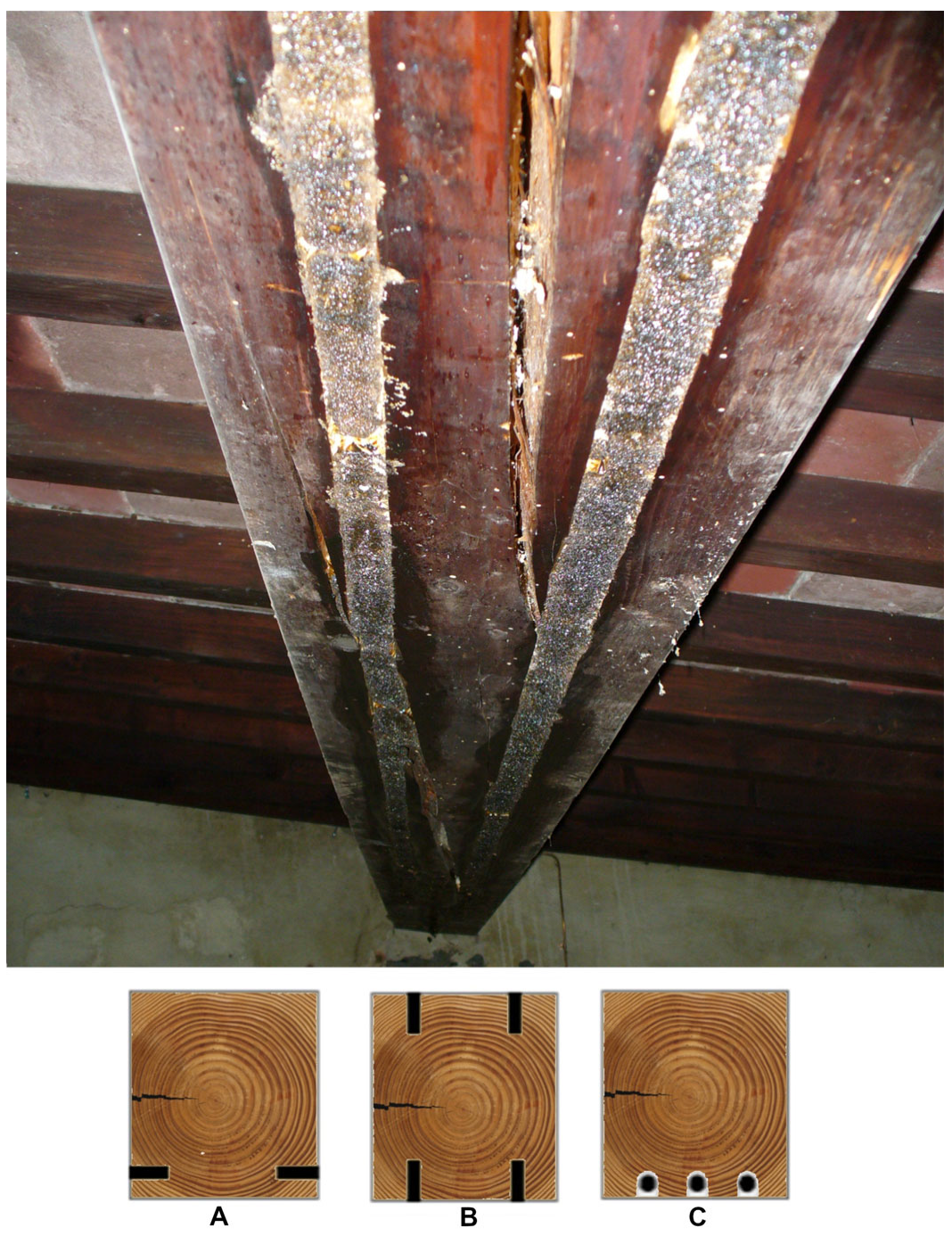
The timber members of existing buildings may require specific on-site interventions, including reinforcement or repair [8]. Upgrading wooden structures to withstand higher working loads or restoring their originally designed strength and stiffness are engineering tasks. Currently, a technique commonly used for strengthening and repairing timber consists of embedding reinforcing materials (e.g., steel plates, pultruded fiberglass rod, carbon-fiber-reinforced plastic (CFRP), etc., typically bonded with epoxy resins) in grooves routed into the original sound wood [9,10,11,12,13,14] (Figure 1).
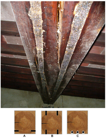
Figure 1.
(Top): Ancient structures with an old timber beam strengthened at the intrados face via inserting steel plates into grooves routed along the longitudinal axis. (Below): Examples of some types of grooving that involve insertion for internal glued reinforcement arrangement: A, placing fiber-reinforced polymer (FRP) strips close to the intrados; B, incorporation of steel plates; and C, inclusion of pultruded fiberglass rods on intrados.
Many papers present the results of tests performed on specimens of various sizes and different species to determine the best strengthening strategy to improve mechanical performance both for new timber and ancient elements [10,15,16,17,18]. The results of such studies are not always in agreement. For instance, Duarte et al. [16] observed that the modulus of rupture (MOR) of strengthened timber elements did not increase for some techniques. Alam et al. [17] recorded the MOR and modulus of elasticity (MOE) as increasing for only some of the investigated techniques. Schober and Rautenstrauch [15], among diverse other intervention proposals, tested four old timber beams reinforced with CFRP that were bonded centrally to the tension zone in a vertical slot; they observed a minimal MOE increase (+2.8%), considered negligible, for this intervention. Similarly, Alhayek and Svecova [12] strengthened 20 salvaged timber stringers with glass-fiber-reinforced polymer (GFRP) laminates and obtained a very small increase in stiffness (EJ) of 3.3%, with a minimum of −0.36%. However, in general, reinforced timber elements show increases in the load bearing capacity, ultimate strength, and ductility after intervention, although the increase in stiffness is lower.
The limit states’ criteria design (both ultimate and serviceability) must be carefully evaluated when planning strengthening interventions for old timber structures are planned. Design data on bending strength must be considered to avoid failures, and the stiffness of timber elements is fundamental to preserving the historical structures from excessive deformation, which could become irreversible over time. A common problem facing such structures is meeting the serviceability limit states criteria because the MOE is often the factor limiting the design of wooden structures. Additionally, as the principle of minimizing interventions is universally recognized as fundamental for the conservation of the integrity of historical timber structures [1], the MOE of the residual beam is vital, especially when a strengthening intervention is planned for wooden cultural heritage.
All the above-described studies considered the MOE as a material property, unchangeable and unaffected by any operation, even after forming grooves. This concept cannot always be applied to wood as a material because wood is affected by the presence of natural defects and anomalies, the effects of which depend on their dimension and position. Interruptions of grain continuity along the span and around knots, as well as the interactions between grooves and other wood anomalies, as a consequence of forming grooves, could affect the mechanical properties of wood; these effects may be stronger than the reduction in the amount material caused by the removal of a portion of beam [13,19]. Particularly, Cavalli and Togni [19] found a strict direct relationship between the reduction in MOE and shrinkage fissures, and an unexpected relationship between grain straightness and decreases in the MOE.
If the current requirements for strengthening interventions are to respect the original construction and to preserve as much of the original material as possible, reinforcing projects must consider any effects of grooves on the original mechanical properties of the wood. For instance, when a strengthening intervention is targeted to increase beam stiffness, the project should be planned to add the necessary strengthening material; however, if the grooves needed to insert the additional material reduce the original stiffness, the strengthening ratio must be increased. To maintain the integrity of the original material and minimize the extent of the intervention, the proposed strengthening techniques need to consider all potential factors that may cause variations in the original mechanical properties. This is crucial, as adopting a different approach might result in ineffective outcomes (e.g., in an experimental strengthening intervention [15]).
The aim of this study was to investigate how much grooves routed along the length of old timber members affected the bending MOE and how to predict it. Such information is useful for the evaluations and strengthening intervention plans based on a modern approach that includes the concepts of minimizing repair and respecting the original structural members. To facilitate the work of structural engineers, their evaluations, and designs, the results of this study were used to develop two simplified methods to assess the weakening effect caused by grooves on the MOE of timber.
2. Materials and Methods
2.1. Timber Beams
Twelve old beams of silver fir (Abies alba Mill.) were disassembled and reclaimed from various ancient buildings in the Tuscany region, close to Florence (Italy), where they had been incorporated as wooden flooring or structural roof elements, and had underwent restoration work. According to historical information, all the beams were older than 70 years. Their cross-sections were different, in the range of 16 × 14 to 28 × 22 cm. All the defects could have affected the structural behavior of each timber member were recorded and measured: slope of the grain, knots, wanes, position of the pith (11 beams with boxed hearts and piths inside), and extension of fissures (the ratio between the fissure depth and the cross-section width). Such defects, which varied in size and influence on the mechanical properties, were considered in terms of their position, size, and characteristics. The positions of the piths and the measurements of the fissures are reported in Table 1. More detailed information about the tested beams was previously reported [19].

Table 1.
Data of sampled timber beams and effect of routed groove on J and E.
2.2. Grooves
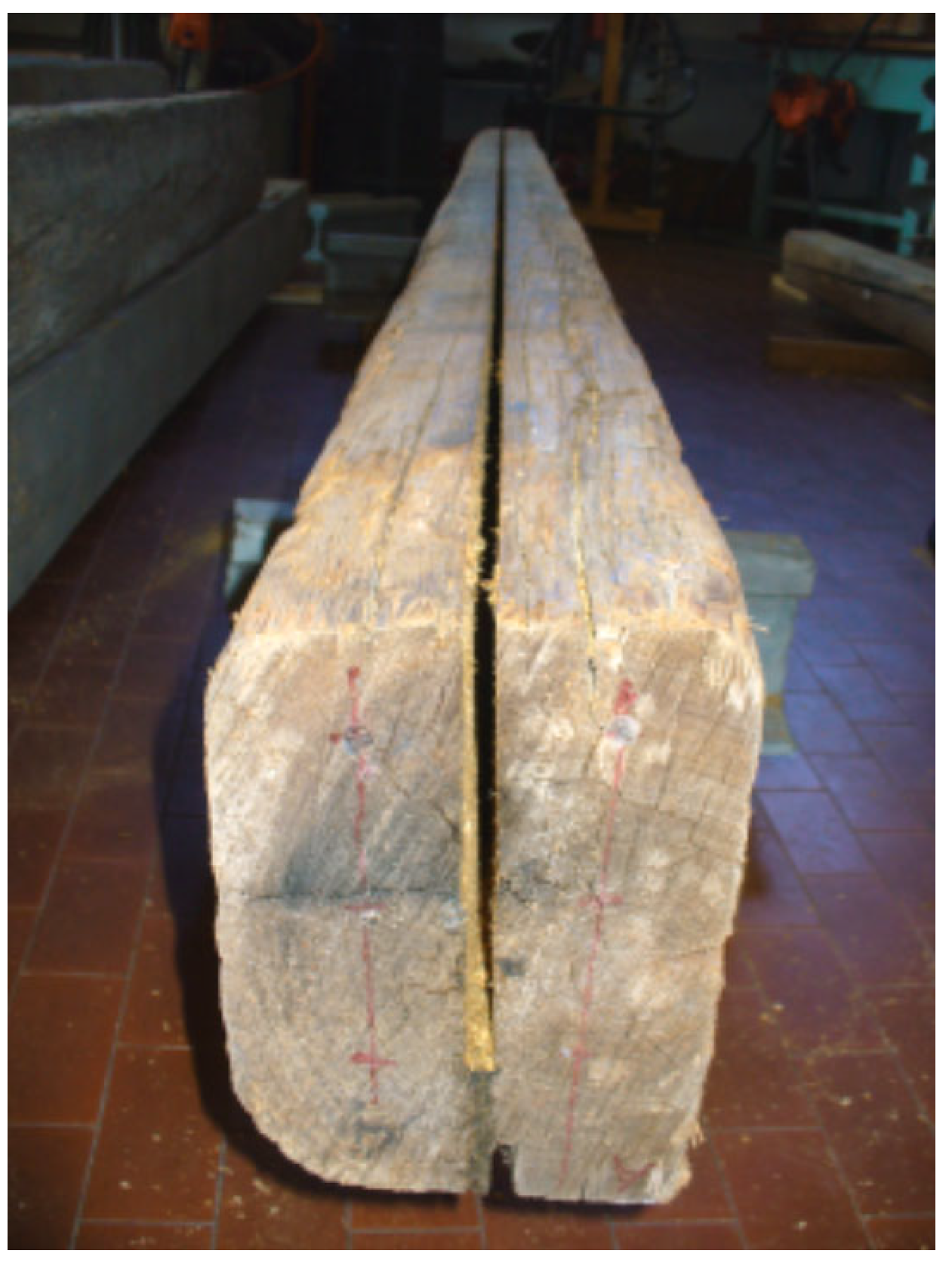
To simulate strengthening interventions, a single groove was routed on the intrados face along the entire length of each beam using an electrical chainsaw while controlling depth and position. The groove depth was progressively deepened in three steps to mimic practice, e.g., 25% of the beam depth in the first step, 50% of the beam depth in the second step, and then 75% in the third step.
The executed grooves were narrow (approximately 9 mm) (Figure 2), and the moment of inertia (J), also called second moment of area, on the centroid position was recalculated on the actual cross-section as its value changed after the creation of each groove. After each woodworking process, a small quantity of wood was removed, and J decreased; in the worst case, this decrease was 3.7% in beam no. 1 after the third step.

Figure 2.
Beam no. 3 after the third groove to 75% of the depth.
2.3. Mechanical Tests
To calculate the global MOE (Em,g), the test geometry was planned as four-point bending tests, dividing the length of the beam in three parts of equal lengths (1/3 of the full length), based on the European standard [20]. Em,g was chosen because it is easy to measure (potentially on-site using a proof-loading test), and monitoring the behavior of the full beam was easy. The static-bending MOE (Em,g) was calculated using Equation (1) [20].
where Em,g is the global MOE (MPa); ΔP is the load increase in the elastic range (N); a is the distance between the support and the load application point (mm); l is the testing span (mm); J is the moment of inertia (mm4) recalculated after each groove, with index i for the 4 different testing conditions; and Δη (mm) is the intrados displacement measured at a given ΔP.
The timber elements were tested at the same intrados/extrados position, whereas the cut was deepened on the intrados. As the sample comprised 12 beams, a total of 48 tests were conducted, i.e., 4 tests per beam to determine 4 MOEs. The test was performed within the elastic range of the beams before and after cutting the first groove as well as after each deepening of the groove. Identical stress was applied while maintaining the testing geometry, utilizing the loading speed specified in EN 408 [20], through the use of a Metro-COM testing machine. In the laboratory, we maintained testing conditions of a temperature of 20 ± 2 °C and a relative humidity of 65 ± 5%.
2.4. Dynamic Tests
Various dynamic tests were conducted to predict the MOE and develop specific techniques for the on-site assessment of the MOE reduction caused by the creation of grooves. We did not use an automatic timber-grading system (e.g., a strength-grading machine (SGM)) to assess the MOE and its variation because many SGMs are not usable on site because of their dimensions, and none are calibrated for testing old beams with a groove on the intrados/extrados. To reduce the influence of the boundary conditions during all the dynamic tests, the beams were suspended at their theoretical nodal points for fundamental vibration mode in flexural vibration (0.224 of the length). All the dynamic tests were conducted using coaxial piezoelectric accelerometers connected to a notebook PC and a digital storage oscilloscope. Piezoelectric accelerometers are affordable and easy to use on-site, owing to their compact dimensions and their self-powering system; they offer accurate measurements for low vibrations with a very low noise level.
The dynamic MOEs were calculated for the following conditions: no grooves, and grooves at 25%, 50%, and 75% of the cross-section depth.
In the flexural vibration tests, vibration was induced using a hammer impact, and data were collected using an accelerometer connected to a notebook PC. The resonance frequency was determined via FFT analysis using GS Spectrum Analyser software, version 4.0. The dynamic flexural MOE (Ef) was calculated using Equation (2) [21].
where Ef is the dynamic flexural MOE (MPa), f1 is the fundamental vibration frequency (kHz), l is the beam length (m), J is the moment of inertia (m4) calculated for each testing condition, m is the beam weight (kg), and k is a constant corresponding to the fundamental mode of free–free flexural vibration.
In the longitudinal vibration tests, an accelerometer was fixed at one end, and the opposite end was hit with a hammer. The vibration frequency was recorded, and the dynamic MOE was determined according to Equation (3) [22].
where El is the dynamic longitudinal MOE (MPa), ρ is the density (kg/m3), f1 is the fundamental vibration frequency (kHz), and l is the beam length (m).
For the stress wave transmission time test, each beam was excited with a hammer impact after two accelerometers were fixed on the beams ends. The accelerometers were connected to a digital storage oscilloscope: the one nearer to the hit end started a microsecond counter, and the second one stopped it, thus providing the time for the impact stress wave to travel between the two ends. The velocity of the stress waves was calculated by dividing the beam length by the flight time of the stress waves [23], and the dynamic MOE was calculated using Equation (4):
where Esw is the dynamic stress-wave MOE (MPa), ρ is the wood density (kg/m³), and v is the stress-wave velocity (km/s).
3. Results
3.1. MOE Reduction
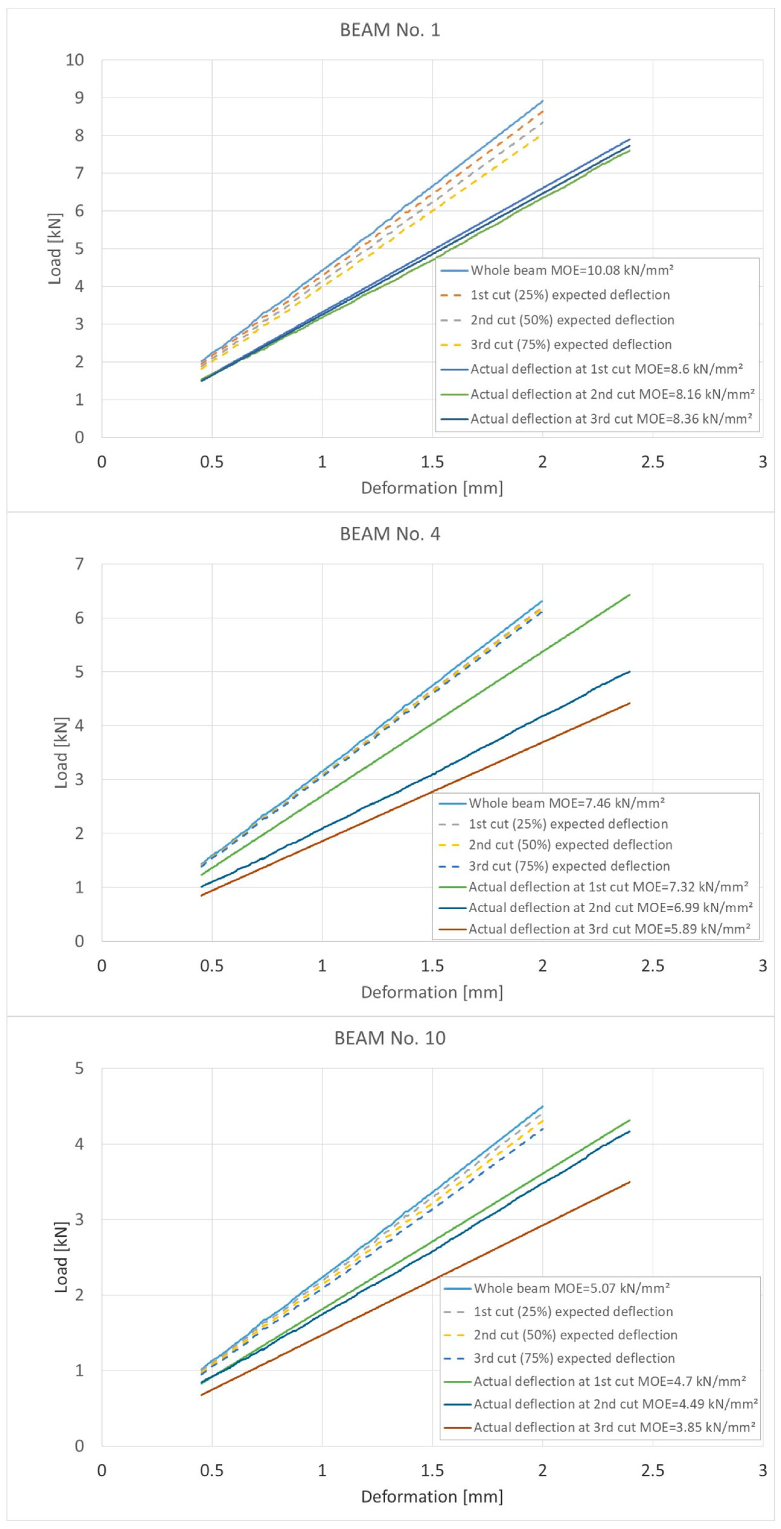
The average MOE was low compared with that of new, sound wood, as expected for beams with several defects such as knots, grain slope, and unknown load history. In general, all the beams showed a reduction in MOE that was larger than the reduction in J (Figure 3), which was a consequence of the interactions between the groove and beam characteristics. Such interactions reduce the original timber quality, causing a general degradation of their mechanical behavior:
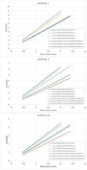
Figure 3.
Load–deformation graphs of beam Nos. 1, 4, and 10. Comparison between natural beam and beam with grooves. Differences between expected and actual stiffness reductions are shown.
- -
- Interrupting the grain continuity [24,25];
- -
- Cutting the fiber around the knots and increasing the stress in their proximity [26];
- -
- Interactions between shrinkage fissures and groove depth [19].
Cavalli and Togni [19] observed that the distance between this kind of fissure and groove particularly influences reductions in the MOE.
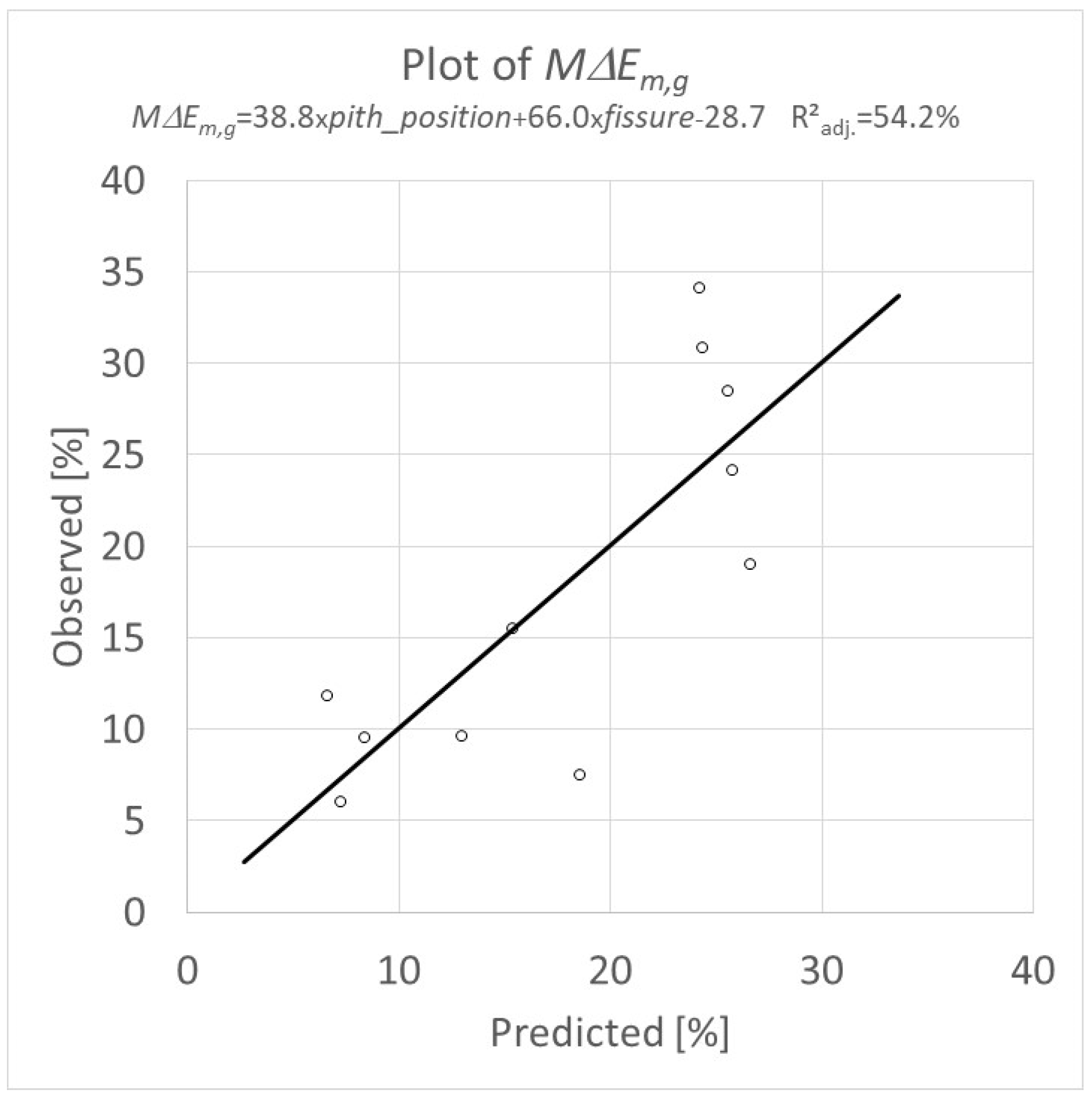
As the pith provides the reference point for the positions of shrinkage fissures, which deepen in its direction in the beam, the shorter the distance between the groove and pith, the larger the MOE reduction. This outcome can be explained by the relationship between the decrease in the maximum MOE (M∆Em,g), the combinations of fissure extensions (with the section width ratio), and the fissure distance from the pith (Equation (5)):
where M∆Em,g is the maximum decrease in the MOE, and pith_position is the ratio between h (pith to intrados distance) and d (cross-section depth), as reported in Table 1. The regression chart is shown in Figure 4.

Figure 4.
Multiple regression: MΔEm,g = −28.7 + 38.8·pith_position + 66.0·fissure; R2adj = 54.2%, p-value = 0.018; mean absolute error (MAE) = 4.90, and mean absolute percentage error (MAPE) = 0.33.
Practical Consequences
The results showed that the described strengthening intervention, designed without considering the potential reduction in MOE, may lead to ineffective results, even if designed respecting the principle of minimum intervention. The design of such an intervention must consider the characteristics of each beam because each beam has a specific reduction MOE for each groove depth. Moreover, the above data were obtained from one small groove, but strengthening interventions based on grooves with comparable depth but with different for numbers and dimensions may produce a stronger weakening effect. Therefore, the on-site assessment of the potential reduction in MOE is of key importance for the design of strengthening interventions to enhance stiffness.
4. Assessment of Reduction in MOE
Two different methods are here proposed for the on-site assessment of reductions in MOE as a result of the creation of grooves. The first one is based on dynamic tests and can be used on timber members after forming grooves making and before the insertion of strengthening materials. The second method can be used prior to groove creation to first estimate the possible reduction in MOE, based on the recording of the visual features of the beams.
4.1. Dynamic Tests
The relationship between the dynamic and static MOEs for the different tests are reported in Table 2. The capacity of the tested techniques to predict the MOE on ancient timber beams has been investigated [19,27]. Although all the techniques are capable of assessing the Em,g with a high or medium correlation (where the correlation level is defined according to [28]), the capacity to predict the maximum reduction in Em,g differs for each dynamic test. For the stress-wave and longitudinal vibration tests, the average maximum reduction in the MOE is small (4% and 7%, respectively, after the third deepening of the groove) compared with that of the static tests (average maximum static MOE reduction of 17%). This difference is a result of the characteristics of the dynamic tests [29,30], which results in an unsatisfactory ability to predict stronger weakening effects. Therefore, for practical purposes, these two techniques are unreliable for the assessment of reductions in the MOE.
Table 2.
Correlation between dynamic and static MOEs.
The flexural vibration test showed a stronger capacity to predict the Em,g and its variation (Figure 5); however, this test requires specific boundary conditions to be arranged on-site, and it underestimates the reduction in Em,g (average maximum Em,g reduction of 17%; average maximum Ef reduction of 11%). As the flexural vibration test can be used on-site only after the creation of grooves (with respect to the boundary conditions), the assessment of the reduction in the MOE under those conditions may help structural engineers to design the intervention to correct the strengthening ratio.
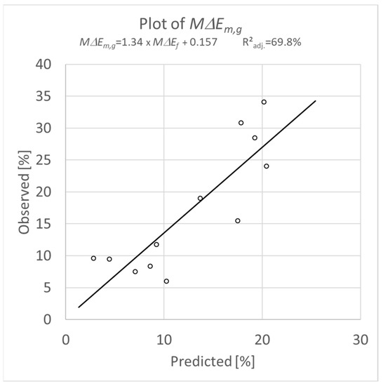
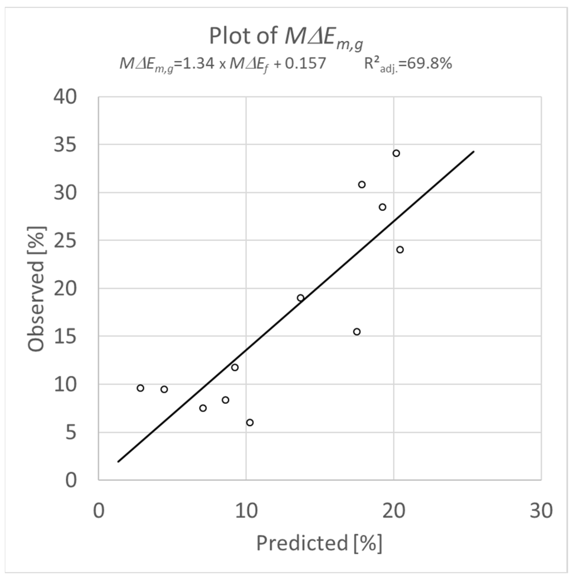
Figure 5.
Relationship between maximum decrease in Ef (MΔEf) and corresponding maximum decrease in Em,g. Simple regression: MΔEm,g = 0.157 + 1.34 × MΔEf; R2adj = 69.8%, p-value = 0.0004; and MAE = 4.29, MAPE = 0.35.
4.2. Visual Survey
In many cases, knowing the potential effect of the grooves on the MOE in advance would be more important in planning strengthening interventions. In this case, the reduction in MOE can be roughly and indirectly assessed by surveying the features of the timber beams that are related to reductions in the MOE.
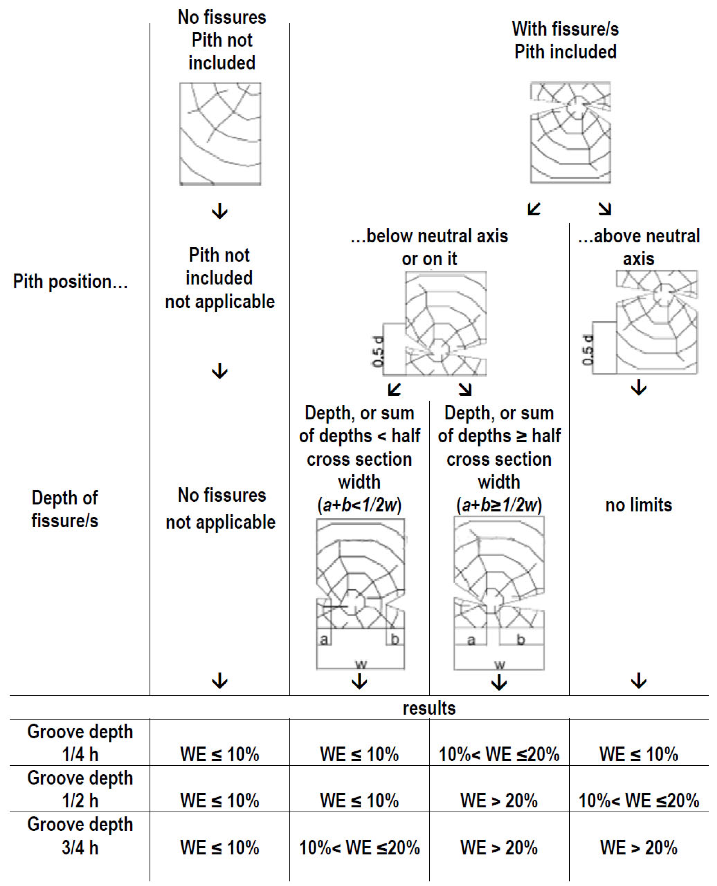
The diagram in Figure 6, based on the outcomes of this study, displays the decreases in Em,g calculated after each groove deepening at the intrados face. For each case, the figure reports the expected potential reduction in Em,g for each groove depth (25%, 50%, and 75% of the cross-section depth). The starting point in Figure 6 is the identification of the presence of shrinkage fissures. If the pith is not included, no fissures exist in the beam or in the bottom part of the figure; the estimated decrease in the MOE is reported for each groove depth. If the pith is included, and fissures are present, the position of the pith must be identified: if the pith is above the neutral axis, proceed to the potential decrease in the MOE; otherwise, if the pith is below the neutral axis, the fissure depth must be considered in relation to the beam width. Due to the large variability in the response of each beam and to the limited number of beams tested, the ranges of values must be considered as an approximation to provide an order of magnitude of the reduction in the MOE for various groove depths. The same diagram can be applied to grooves on the extrados, considering the sections upside-down.
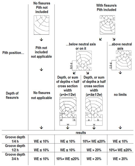
Figure 6.
Assessment of reduction MOE via a visual survey. For each groove depth (25%, 50%, or 75% of the cross-section depth), the weakening effect (WE) expected on the MOE is expressed as the percentage decrease in the MOE. Symbols: a, b = depth of shrinkage fissures, d = cross-section depth, and w = cross-section width.
The diagram considers the presence and extension of the shrinkage fissures and the position of the pith, which are the most important factors affecting reductions in the MOE. In practice, this method must be adopted by experts because other timber features that were not considered in the studied sample could have an additional influence on the MOE and its decrease (e.g., dimensions and position of ring-shakes, presence of localized decay, etc.). The potential effects of grooves on strengthening interventions, which can be variable in number, dimensions, and positions, must be carefully considered.
5. Conclusions
The reduction in the MOE of old timber beams after creating grooves is mainly due to the interactions between grooves and the grain course and between fissures (depth and position) and grooves, indicating the MOE is particularly important in beams with boxed hearts and piths inside.
The higher reduction in MOE that was observed (up to 30%), despite a minimal reduction in J (less than 3.8%), highlighted the need to consider alternative strengthening techniques, without grooves, for specific timber elements. This was because diminishing the stiffness of an element that requires reinforcement could be considered a senseless intervention.
The large variability observed in the MOE reductions after creating grooves suggests a general caution is required when planning strengthening interventions using the described techniques; additionally, the reinforcement design must carefully consider the relevant characteristics of each beam.
Two methodologies for the on-site assessment of potential reductions in MOE were discussed. The first was based on the dynamic test and can be used after the formation of the grooves. The second was based on the specific features of a beam (presence of shrinkage fissures, their positions and extensions, and pith positions) and is useful for assessing reductions in the MOE before the creation of grooves. Both methods, to be used with caution because they are based on the outcomes of a small sample, can aid in the correct design of strengthening operations to be conducted on ancient timber beams.
Author Contributions
Methodology, A.C. and M.T.; Validation, L.R.; Investigation, A.C.; Writing—original draft preparation, A.C.; Writing—review & editing, P.M. and M.T.; Supervision, M.T. and L.R. All authors have read and agreed to the published version of the manuscript.
Funding
This study received no external funding.
Data Availability Statement
Data are available upon request from the corresponding author.
Conflicts of Interest
The authors declare no conflict of interest.
References
- IWC—ICOMOS Principles for the Preservation of Historic Timber Structures. 2017. Available online: https://www.icomos.org/images/DOCUMENTS/General_Assemblies/19th_Delhi_2017/Working_Documents-First_Batch-August_2017/GA2017_6-3-4_WoodPrinciples_EN_final20170730.pdf (accessed on 17 July 2023).
- Kasal, B.; Anthony, R.W. Advances in situ evaluation of timber structures. Prog. Struct. Eng. Mater. 2004, 6, 94–103. [Google Scholar] [CrossRef]
- Tampone, G. Mechanical Failures of the Timber Structural Systems. In From Material to Structure—Mechanical Behaviour and Failures of the Timber Structures; IIWC: Florence, Italy; Venice, Italy; Vicenza, Italy, 2007; p. 21. Available online: http://iiwc.icomos.org/assets/tampone.pdf (accessed on 16 April 2022).
- Palaia, L.; López, V.; Tormo, S.; Pérez, C.; Navarro, P. Assessment of Timber Structures in Service, by Using Combined Methods of Non-Destructive Testing Together with Traditional Ones. In Proceedings of the 9th International Conference on NDT of Art, Jerusalem, Israel, 25–30 May 2008; pp. 25–30. Available online: http://www.ndt.net/article/art2008/papers/060Palaia.pdf (accessed on 17 July 2023).
- Pinto, L. Inventory of Repair and Strengthening Methods Timber. Master‘s Thesis, University of Minho, Braga, Portugal, 2009. Available online: http://upcommons.upc.edu/pfc/bitstream/2099.1/7903/1/01.pdf (accessed on 17 July 2023).
- Stumes, P. Testing the Efficiency of Wood Epoxy Reinforcement Systems. Bull. Assoc. Preserv. Technol. 1975, 7, 2–35. [Google Scholar] [CrossRef]
- Piazza, M.; Riggio, M. Typological and Structural Authenticity in Reconstruction: The Timber Roofs of Church of the Pieve in Cavalese, Italy. Int. J. Archit. Herit. 2007, 1, 60–81. [Google Scholar] [CrossRef]
- Cavalli, A.; Cibecchini, D.; Togni, M.; Sousa, H.S. A review on the mechanical properties of aged wood and salvaged timber. Constr. Build. Mater. 2016, 114, 681–687. [Google Scholar] [CrossRef]
- Tampone, G. Il Restauro Delle Strutture di Legno; Hoepli: Milano, Italy, 1996; pp. 305–325. [Google Scholar]
- Gentile, C.; Svecova, D.; Rizkalla, S.H. Timber beams strengthened with GFRP bars: Development and applications. J. Compos. Constr. 2002, 6, 11–20. [Google Scholar] [CrossRef]
- Rotafix, Timber Resin Splice. 2018. Available online: http://rotafix.co.uk/wp-content/uploads/2016/09/TRS-Brochure.pdf (accessed on 17 July 2023).
- Alhayek, H.; Svecova, D. Flexural Stiffness and Strength of GFRP-Reinforced Timber Beams. J. Compos. Constr. 2012, 16, 245–252. [Google Scholar] [CrossRef]
- Arriaga, F.; Iñiguez-Gonzalez, G.; Esteban, M.; Fernandez-Cabo, J.L. Simplified model for strength assessment of timber beams joined by bonded plates. J. Mater. Civ. Eng. 2013, 25, 980–990. [Google Scholar] [CrossRef]
- Salčin, M.; Džubur, Ž.; Ćatović, F.; Džiho, E. Strengthening Timber Structure with Fiber Reinforced Polymer—An Overview. In New Technologies, Development and Application V. NT 2022; Lecture Notes in Networks and Systems; Karabegović, I., Kovačević, A., Mandžuka, S., Eds.; Springer: Cham, Switzerland, 2022; Volume 472. [Google Scholar] [CrossRef]
- Schober, K.U.; Rautenstrauch, K. Post-strengthening of timber structures with CFRP’s. Mater. Struct. 2007, 40, 27–35. [Google Scholar] [CrossRef]
- Duarte, A.; de Oliveira Negrão, J.; Cruz, H.; Balseiro, A. Bending strength of timber beams rehabilitated with reinforced epoxy mortar plates. J. Struct. Eng. 2008, 34, 792–800. [Google Scholar] [CrossRef]
- Alam, P.; Ansell, M.; Smedley, D. Mechanical repair of timber beams fractured in flexure using bonded-in reinforcements. Compositesb 2009, 40, 95–106. [Google Scholar] [CrossRef]
- Jankowski, L.J.; Jasieńko, J.; Nowak, T.P. Experimental assessment of CFRP reinforced wooden beams by 4-point bending tests and photoelastic coating technique. Mater. Struct. 2010, 43, 141–150. [Google Scholar] [CrossRef]
- Cavalli, A.; Togni, M. The influence of routed grooves on the bending behaviour of old timber beams. Adv. Mater. Res. 2013, 778, 393–401. [Google Scholar] [CrossRef]
- EN 408 Timber structures. Structural Timber and Glued Laminated Timber; Determination of Some Physical and Mechanical Properties; European Committee for Standardization: Brussels, Belgium, 2012. [Google Scholar]
- Giordano, G. Tecnologia del Legno, 2nd ed.; UTET: Torino, Italy, 1981; pp. 314–315. [Google Scholar]
- Kollman, F.; Krech, H. Dynamische Messung der elastischen Holzeigenschaften und der Dampfung. Holz Roh-Werkst. 1960, 18, 41–54. [Google Scholar] [CrossRef]
- Kolsky, H. Stress Waves in Solids; Dover Publication: New York, NY, USA, 1963; pp. 74–141. [Google Scholar]
- Arriaga, F.; Herrero, M.; Álvarez, R.; Maldonado, I. Efecto de las gemas en la resistencia a flexión de piezas enterizas de madera. The effect of wanes on the bending strength of solid timber beams. Mater. Construcc. 2007, 57, 61–76. [Google Scholar] [CrossRef]
- Togni, M.; Cavalli, A.; Mannozzi, D. Chestnut: From coppice to structural timber. The case study of “Uso Fiume” beams sampled in Liguria. J. Agric. Eng. 2013, 44, 1–9. [Google Scholar] [CrossRef]
- Ranta-Maunus, A. Round Small-Diameter Timber for Construction. Final Report of Project. 1999. Available online: https://www.vttresearch.com/sites/default/files/pdf/publications/1999/P383.pdf (accessed on 17 July 2023).
- Cavalli, A.; Togni, M. How to improve the on-site MOE assessment of old timber beams combining NDT and visual strength grading. J. Nondestruct. Test. Eval. 2013, 28, 252–262. [Google Scholar] [CrossRef]
- JCSS. Probabilistic Model Code Part 3: Resistance Models. 3.5.3.3. 2006, p. 7. Available online: https://www.jcss-lc.org/publications/jcsspmc/timber.pdf (accessed on 17 July 2023).
- Bodig, J.; Jayne, B.A. Mechanics of Wood and Wood Composites; Van Nostrand Reinhold: New York, NY, USA, 1982; pp. 103–104. [Google Scholar]
- Andrews, M. Which acoustic speed? In 13th International Symposium on Non-Destructive Testing of Wood; University of California: Berkeley, CA, USA, 2002; pp. 159–165. [Google Scholar]
Disclaimer/Publisher’s Note: The statements, opinions and data contained in all publications are solely those of the individual author(s) and contributor(s) and not of MDPI and/or the editor(s). MDPI and/or the editor(s) disclaim responsibility for any injury to people or property resulting from any ideas, methods, instructions or products referred to in the content. |
© 2023 by the authors. Licensee MDPI, Basel, Switzerland. This article is an open access article distributed under the terms and conditions of the Creative Commons Attribution (CC BY) license (https://creativecommons.org/licenses/by/4.0/).