Article

Experimental Study of Beam Stability Factor of Sawn Lumber Subjected to Concentrated Bending Loads at Several Points

1
Forest Products Department, Faculty of Forestry and Environment, IPB University (Bogor Agricultural University), Kampus IPB Dramaga, Bogor 16153, Indonesia
2
Civil Engineering Study Program, Faculty of Engineering, Pakuan University, Bogor 16129, Indonesia
3
Civil and Environment Engineering Department, Faculty of Agricultural Technology, IPB University (Bogor Agricultural University), Kampus IPB Dramaga, Bogor 16153, Indonesia
*
Author to whom correspondence should be addressed.
Forests 2022, 13(9), 1480; https://doi.org/10.3390/f13091480
Submission received: 18 August 2022 / Revised: 7 September 2022 / Accepted: 11 September 2022 / Published: 14 September 2022
(This article belongs to the Section Wood Science and Forest Products)

Abstract

:
The beam stability factor (CL) is applied in construction practices to adjust the reference bending design value (Fb) of sawn lumber to consider the lateral-torsional buckling. Bending tests were carried out on 272 specimens of four wood species, namely, red meranti (Shorea sp.), mahogany (Swietenia sp.), pine (Pinus sp.), and agathis (Agathis sp.), to analyze a simply supported beam subjected to concentrated loads at several points. The empirical CL value is a ratio of the modulus of rupture (SR) of a specimen to the average SR of the standard-size specimens. The non-linear regression estimated the Euler buckling coefficient for sawn lumber beam (KbE) in this study as 0.413, with 5% lower and 5% upper values of 0.338 and 0.488. Applying the 2.74 factor, which represents an approximately 5% lower exclusion value on the pure bending modulus of elasticity (Emin) and a factor of safety, the adjusted Euler buckling coefficient (KbE) value for a timber beam was 1.13 (0.92–1.34), which is within the range approved by the NDS (KbE = 1.20). This study harmonizes the NDS design practices of CL computation with the empirical results. Because agathis has the lowest ductility (μ), most natural defects (smallest strength ratio, S), and highest E/SR ratio, the agathis beam did not twist during the bending test; instead, it failed before twisting could occur, indicating inelastic material failure. Meanwhile the other specimens (pinus, mahogany, and red meranti), which have smaller E/SR ratio, higher ductility, and less natural defects, tended to fail because of lesser beam stability. This phenomenon resulted in the CL curve of agathis being the highest among the others. The CL value is mathematically related to the beam slenderness ratio (RB) and the E/SR ratio. Because the strength ratio (S) and ductility ratio (μ) have significant inverse correlations with the E/SR ratio, they are correlated with the CL value. Applying the CL value to adjust the characteristic bending strength is safe and reliable, as less than 5% of the specimens’ SR data points lie below the curve of the adjusted characteristics values.

1. Introduction

Timbers are often used as structural components such as beams, columns, and trusses in residential housing [1], multi-story buildings [2], cooling towers [3,4,5], and bridges [6]. Beam design involves analyzing member strength, stability, and stiffness for four essential criteria (e.g., bending (including stability), deflection, horizontal shear, and bearing). In addition to mechanical resistance and serviceability, a designer must verify other requirements (e.g., environmental condition, durability aspects, fire resistance, and fatigue) to build a timber construction. Timber beam strength is commonly determined through edgewise bending tests with the loads applied to the narrow face [7,8]. Edgewise bending stiffness and strength are the essential grade-determining properties (GDP) in wood strength grading, and can be predicted by the flatwise modulus of elasticity [9]. Timber grading machines based on edgewise bending excitation are available in the European market; however, their applications are limited [10] because a greater applied load is needed to bend timber edgewise than flatwise.
Columns and beams can be categorized as short, intermediate, and long according to the slenderness ratio (λ) and beam slenderness ratio (RB), respectively. A rectangular cross-sectional wooden column is long if the ratio of the length to the least cross-sectional dimension (L/h) range is 27–50, following the Rankine–Gordon formula [11], while a round bamboo culm beam is long if the slenderness ratio (λ) is more than 30.5 for Guadua [12] and 32 for G. apus [13], following the Ylinen formula. While buckling does not occur in a short beam or column [14,15] it usually does for intermediate or long ones. A beam slenderness ratio (RB) less than 11 indicates a short beam, while an RB range of 11–50 indicates intermediate and long beams [16].
A slender beam tends to buckle and torsion, which is known as lateral–torsional buckling. Lateral–torsional buckling occurs on fixed [17], cantilevered [18], and a single-span beams [19]. Beams with square cross-sections are not susceptible to lateral–torsional buckling. ASTM D143 [20] designates the square cross-section bending test specimen (5 × 5 × 76 cm3 primary method and 2.5 × 2.5 × 41 cm3 secondary method); thus, many researchers [4,5,12,21,22,23] have chosen it as a standard specimen in bending tests. Following the British Standard [24], static bending tests are carried out on 2 × 2 × 30 cm3 dimension specimens as well [22,25]. Lateral–torsional buckling does not occur for circular cross-section beams [26], hollow circular cross-sectional beams (e.g., plumbing [27], bamboo [28,29,30]), or box beams [31]. Lateral–torsional buckling occurs when a slender beam is subjected to bending loads; deformation occurs until it reaches its critical load [32], then the beam deflects out-of-plane accompanied by twisting. Beam deformation includes in-plane deformation, out-of-plane deformation, and twisting [33], all of which are involved when lateral–torsional buckling occurs. Lateral supports need to be applied to limit these deformations and ensure beam stability. Beams with sufficient lateral support are not susceptible to lateral–torsional buckling. Suryoatmono and Tjondro studied the lateral–torsional buckling of a rectangular beam loaded by a concentrated load [34]. The beam was laterally supported at both ends, and the results showed that the beam reached its critical load without rotating.
Lateral buckling may occur on slender beams, and can govern beam failure; thus, lateral support must be provided to prevent rotation when the depth of the long bending member exceeds its width (d > b) [35]. The beam stability factor (CL) is applied to adjust the reference bending design value of timber structure components subjected to bending [33,35,36] in order to consider the effect of lateral–torsional buckling.
The distance between lateral support points along the beam length, termed the unsupported length (lu), affects the beam stability factor (CL). The unsupported length lu is converted into the effective span length (le) following the beam loading configuration. The beam slenderness ratio (RB), which is calculated following Equation (1), is the basis for stability design in beams. The allowable bending stress (Fb) in beams is specified based on the beam slenderness ratio for the three ranges: short beams (RB ≤ 10), intermediate beams (11 < RBCk), and long beams (Ck < RB ≤ 50). The beam stability factor (CL) formulas were derived by Zahn [37] for three separate ranges (Equations (2–4)) and adopted by the National Design Specification (NDS) 1986 [38]. In the equation, F b is the allowable bending stress, E is the modulus of elasticity, and RB is the beam slenderness ratio. The transition point of the beam slenderness ratio between intermediate and long beams (Ck) is calculated following Equation (5). Zhan [39] reevaluated the NDS 1986 [38] CL formula by deriving an elastic buckling criterion for simply supported beams under any combination of strong-axis bending loads, weak-axis bending loads, axial compression, equal end couples, and water ponding to account for the interaction between bending moment and axial compression.
NDS has adopted a single continuous CL formula (Equation (6)) since 1991, which applies to all range of beam slenderness ratio (RB) and replaces Equations (2)–(4) for determining the effects of beam slenderness ratio on allowable bending design values (Fb). The Euler buckling coefficient for a beam (KbE) in the NDS 1991 [40] was 0.438, replacing the value of 1.44/3.3 in Equation (4). The design formula (Equation (6)) was proposed by Zahn [41], which simplified the Ylinen column buckling formula by setting its non-linear parameter for beam (c) equal to 0.95. This CL formula (Equation (6)) is more accurate and general for beam slenderness ratios less than 50 (RB < 50) and is designated in the current NDS. The Indonesian National Standard (SNI) 7973:2013 [33], which recently adopted the NDS 2012 [35], proposes this CL formula as well. The FbE factor in Equation (6) is the critical buckling design value, which is calculated following Equation (7).
R B = l e d b 2
F b = F b ,   for   short   beam   ( R B   10 )
F b = F b 1 1 3 R B C k 4 ,   for   intermediate   beam   ( 11   <   R B   C k )
F b = 1 . 44 E 3 . 3 R B 2 ,   for   long   beam   ( C k   <   R B   50 )
C k = 0 . 811 E F b
C L = 1 + F bE F b * 1 . 9 1 + F bE F b * 1 . 9 2 F bE F b * 0 . 95 ,   for   ( R B   50 )
F bE = K bE   E R B 2 = 0 . 438 E R B 2
After 1997, the NDS has chosen to report Emin rather than E; thus, the KbE value of 0.438 is replaced with 1.20 of the adjusted Euler buckling coefficient (KbE) (Equation (8)) to correspond to the factor of 2.74. The factor of 2.74 represents a 5% lower exclusion value of the modulus of elasticity (Emin) (1.03 times tabulated E values) and a safety factor of 1.66 [16]. The FbE calculation by KbE and Emin follows Equation (8). The SNI 7973:2013 [33] and the current NDS currently designate this value.
F bE = K bE   E min R B 2 = 1 . 20 E min R B 2
Several reports on timber beam stability subjected to bending are available in the literature. Hindman et al. [18] studied lateral–torsional buckling on rectangular cantilever beams to validate the CL formula and reported that the CL formula was non-conservative for Laminated Veneer Lumber (LVL), although it was suitable for solid sawn lumber. Kimble and Bender [42] studied the stability of built-up timber beams with various E values in which the beam has a slenderness ratio value of 26.20 (unbraced long beams); their results showed that the obtained CL value was low. Du et al. [43,44] reported that the deck-board stiffness significantly affected the lateral–torsional buckling capacity of twin-beam deck systems. Hu et al. [45,46] developed an energy-based solution to analyze the lateral–torsional buckling of a wooden beam with a midspan lateral brace and indicated that such beams were prone to symmetric and antisymmetric mode buckling patterns. St-Amour and Doudak [47] conducted a sensitivity analysis on a wood I-joist and determined that the critical buckling load is affected by the longitudinal modulus of elasticity, the transverse shear modulus of the flanges, and the elastic modulus of the web. They determined that the equivalent moment factor theory is more adaptable than the Euler elastic buckling theory to predict the I-joist’s critical buckling moment [48]. Sahraei et al. [49] proposed a simplified expression to account for moment gradient, load height, and pre-buckling deformation effects for elastic lateral–torsional buckling of wooden beams.
The available standards designate various methods for designing a beam able to resist lateral–torsional buckling, however, these approaches are significantly different and lack consistency [50]. Balaz [51] proposed formulas to harmonize the different rules in the Eurocode concerning critical moments and suggested replacing the warping constant of a solid rectangular cross-section beam. AFPA [52] described the basis of the current effective length approach used in the NDS and summarized the equivalent uniform moment factor approach, providing a comparison between the two approaches and proposing modifications to the NDS design provisions. The present study aims to analyze the response of beams made from several locally available commercial lumber varieties subjected to concentrated loads at several points in order to validate the beam stability factor (CL) formula designated by NDS 2012 [35], which has been adopted by SNI 7973:2013 [33]. Because red meranti, mahogany, pinus, and agathis sawn lumber are abundantly available in the building material market and are commonly used for structural construction members, they were chosen as the specimens in this study. Center point loading bending tests of small clear specimens and several point loading bending tests of full-sized specimens were conducted to measure the empirical beam stability factor (CL,e), then the non-linear regression was employed to estimate the KbE value. The empirical CL values, estimated best-fit curve, and 5% upper and 5% lower curves were plotted in Cartesian Diagrams together with the building code’s designated graph to justify the harmony of the empirical and designated CL values.

2. Materials and Methods

2.1. Specimen Preparation

The materials were 272 pieces of specimens consisting of 200 small pieces (2.5 × 2.5 × 41) cm3 and 72 full-size pieces (4 × 10 × 130) cm3. The specimens were sawn lumber of red meranti (Shorea sp.), mahogany (Swietenia sp.), pine (Pinus sp.), and agathis (Agathis sp.) purchased from commercial timber markets in Bogor, West Java–Indonesia. All specimens were air-dried in indoor environmental conditions (27 °C and 80% RH) for a month to reach equilibrium moisture content. All experimental work was undertaken in the Wood Engineering Laboratory, Faculty of Forestry and Environment, IPB University (Bogor, Indonesia).

2.2. Small Specimen Bending Test

The small specimens of red meranti, mahogany, pine, and agathis, 50 pieces each, were prepared for the bending test. The length (L), width (b), and depth (d) of each specimen were measured employing a digital caliper with an accuracy of 0.01 mm. The masses were measured three times: before the bending test (m0), after the bending test (m1), and after oven-drying (mot). The oven-drying was carried out at (103 ± 2) °C for two days to evaporate water content in the specimens. Moisture content measurements were conducted soon after the bending test. The moisture content (Mc) was calculated following Equation (9).
M c = m 1 m ot m ot   100 %
The static bending test was carried out following the ASTM D143 secondary method [20] (Figure 1). The span of the specimen was 360 mm in order to maintain a span-to-depth ratio of 14. The specimens were then bending tested with center-point loading using a five-ton capacity Instron type 3369 Universal Testing Machine (UTM). Both supports were rollers with 2 cm diameter. The load was applied continuously throughout the test at the movable crosshead motion rate of 1.3 mm/min. The modulus of elasticity (E) and modulus of rupture (SR) values were calculated following Equations (10) and (11). The E values were calculated within the proportional region of the load–deflection curve.
E = PL 3 4 Δ bd 3
S R = 3 P max L 2 bd 2
The small specimens’ E and SR statistics data, including the mean, standard deviation (s), minimum value, maximum value, and coefficient of variance (CV), were summarized. The 5% exclusion limit (R0.05) values of E and SR were calculated to determine the bending strength characteristic value (Rk) following ASTM D2915 [53] and D5457 [54]. Normal, lognormal, and Weibull standard distributions were applied to fit the experimental data, and the best choice was determined through the Anderson-Darling test [8,12,13].
Material ductility may affect the beam stability. Ductility is a structure’s ability to undergo significant deformation in the plastic ranges before its collapse [55], which is often expressed as the ratio between ultimate displacement (∆u) and yield displacement (∆y) (Equation (12)) [55]. Muñoz et al. [56] stated the ultimate and yield displacement ratio in Equation (12) as the ductility ratio (μ), while Jorissen and Fragiacomo [57] termed it the ductility factor. Ultimate displacement (∆u) is the displacement at the ultimate load (Fu), while yield displacement (∆y) can be calculated following several methods suggested by researchers [58,59,60] and standard specifications [61,62,63]. The yield displacement (∆y) in this study is equal to deformation at 0.5Fu following Karacabeyli and Ceccotti [58].
μ = Δ u Δ y

2.3. Full-Size Specimen Bending Test

Full-size specimens of red meranti, mahogany, pine, and agathis, 18 pieces each, were prepared. Every sawn lumber piece was visually graded following ASTM D245 [64] (Figure 2). Defects and imperfections in the wood were identified and measured. Three indicating defects were observed, namely, the slope of the grain, knot diameter, and the presence of shakes, checks, and splits, then converted into strength ratio (S) values.
The length (L) of each specimen was measured employing a tape measure, while width (b) and depth (d) were measured using a digital caliper with an accuracy of 0.01 mm. The mass was measured three times: before the bending test (m0), after the bending test (m1), and after oven-drying (mot). The specimens used for measuring m1 and mot were 4 × 4 × 4 cm3 and were cut near the bending test specimen’s failure position. The Mc value was calculated according to Equation (9). The density (ρ) was calculated in air-dry conditions before the bending test of a full-size specimen (Equation (13)), while the relative density or specific gravity (Gb) was calculated according to Equation (14).
ρ = m 0 L × b × h
G b = ρ ( 1 + M c ) ρ water
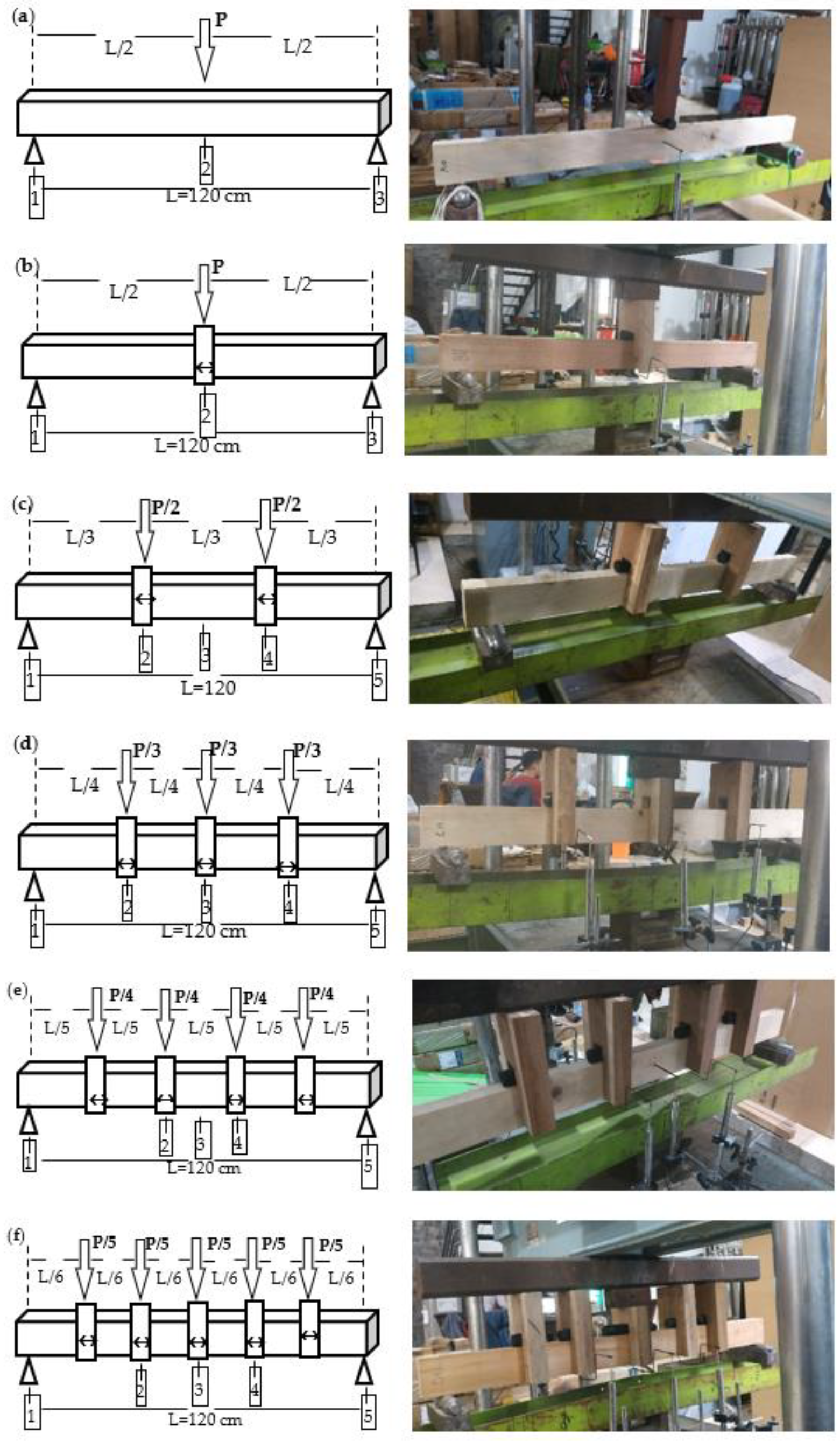
The values of E and SR in the edgewise configuration bending tests were determined employing UTM SATEC/Baldwin. The span of the bending test was 120 cm. The specimens were tested in simply-supported bending with various concentrated loading configurations, namely, center point loading, third point loading, fourth point loading, fifth point loading, and sixth point loading (Figure 3). Lateral supports were applied at every point of loading. Figure 3 shows the position of the five linear variable displacement transducers (LVDTs) which were employed to measure the deflection. As a control, bending tests with a center-point loading configuration and without lateral support were carried out. The formulae of E and SR with various loading configurations are summarized in Table 1.

2.4. Beam Stability Factor (CL) Value Calculation

The effective span length (le) of the beams was determined following Table 2. The beam slenderness ratio (RB) of each specimen was calculated (Equation (1)), while the critical buckling design value of a beam (FbE) was calculated per Equation (7). The empirical CL (CL,e) values from the experimental study were calculated per Equation (15). SRi is the modulus of rupture (MOR) value of each specimen. S R ¯ is the average MOR value of the small-size specimen (b = d = 2.5 cm), tested in bending at a standardized condition following ASTM D143 secondary methods [20].
C L , e = S Ri   /   S R ¯
The non-linear regression model was derived from Equation (6), with FbE substituted by Equation (7), and is presented in Equation (16). Then the non-linear parameter for beam (c) was set to 0.95, E was the small specimens’ average modulus of elasticity, Fb was the experimental value of S R ¯ , and the KbE value was estimated by the regression coefficient (a) (Equation (17)). The non-linear regression analysis with Levenberg–Marquardt algorithm iteration [65] was applied to estimate the empirical value of KbE from experimental results. The starting value of the iteration was 0.438, following Zahn [41].
C L = 1 + K bE E F b R B 2   2 c 1 + K bE E F b R B 2   2 c 2 K bE E F b R B 2   c
y ^ = ( 1 + ax ) 2 c 1 + ax 2 c 2 ax c
where y ^ is the estimated empirical CL obtained through experimental study (CL,e), x is E/( S R ¯ × RB2), c is set to 0.95, and a is the regression coefficient. The regression coefficient (a) estimates the Euler buckling coefficient (KbE).

3. Results and Discussion

3.1. Moisture Content (Mc), Density (ρ), and Specific Gravity (Gb)

Many physical and mechanical properties of wood depend upon its moisture content. The specimens’ average moisture content ranged from 13.45% to 16.98% (Figure 4a), the common air-dry moisture content in Bogor, West Java Indonesia [13,14,66,67,68]. The specimens’ moisture content is within the permissible range in the Indonesian Wooden Building Code (PKKI) regulation [69], which states that the average air-dry moisture content is 15% and its range is 12–18%. The wood density (ρ) depends on its moisture content because both the mass and volume of wood depend upon it. The density of air-dry wood varies significantly between species. The wood relative density or specific gravity (Gb) in this study was referenced based on air-dry volume and oven-dry mass. The average results of ρ and Gb measured in this experimental study are presented in Figure 4, and conform to the ρ value stated in PKKI [69].

3.2. Flexural Properties of the Small Specimens

The average modulus of elasticity (E) and modulus of rupture (MOR, SR) values of the small specimens of red meranti, mahogany, pine, and agathis are summarized in Table 3; they were similar to previous reports [70,71,72,73]. Based on their respective E values, red meranti is graded in the E16–E27 strength class, mahogany is E10–E20 strength class, pine is E6–E21 strength class, and agathis is E12–E17 strength class, per SNI 7973:2013 [33]. Similar to Firmanti et al. report on tropical timber [8], the Weibull distribution was the best fit among others for most of the experimental data. The ASTM D5457 [54] standard distribution for wood strength is assumed to be the Weibull distribution, while European countries commonly designate a log-normal distribution. In this study, the Anderson–Darling tests evaluated the goodness of fit of experimental data (modulus of elasticity (E) and modulus of rupture (SR)), and the best-fit distribution was chosen among three standard distribution (Weibull, lognormal, and normal) (Table 4). The characteristic bending values (Emin and Fb) were determined by estimating their 5% exclusion limits. The 5% exclusion limits (R0.05) of E and SR are presented in Table 4, with the best-fit values were shown in bold font.
Ductility is a material’s ability to attain high displacement without losing too much strength. For clear wood, the stress distribution in a bending member is related to the compression zone’s plasticization. For structural timber-containing defects, this only occurs when the defects are located mainly in the compression zone [57]. The bending test’s load-displacement curves (Figure 5) proved that each wood species has a different proportional limit and maximum load. The ductility ratio (μ) of timbers from the experimental results are presented in Table 5. Because the ductility ratio ranges were 2.12–5.32, timber subjected to a bending load may be classified from low to medium ductility according to Eurocode 8 [74]. Agathis had the lowest μ value, which indicates that agathis subjected to bending is the most brittle among other timbers in this study. The agathis specimens were classified as low ductility because their ductility ratio was equal to or less than 4 (μ ≤ 4). At the same time, red meranti, mahogany, and pines varied from low to medium ductility. The μ value is thought to affect the beam stability factor (CL), as the μ is inversely related to E/SR. In this study, agathis had the highest E/SR value (Table 3). Ishiguri et al. [73] previously reported that agathis had a high modulus of elasticity (E) and a low modulus of rupture (SR) value.

3.3. Strength Ratio of the Full-Size Specimens

Wood, as a natural material, has imperfections and defects, which may reduce its strength. The presence of knots [75], the slope of the grain [76], and shakes, checks, and splits can all reduce the E and SR of timber. Imperfections and defects in wood are often used to determine the wood quality class using visual grading. Visual grading is conducted by converting wood imperfections and defects into a strength ratio (S) to be applied to adjust the strength of a wooden member [77]. S is the ratio of wood strength with defects on its surface to the clear specimen wood strength, and is expressed as a percentage (%) [78]. The S value of the full-size specimens in this study is presented in Table 6. Red meranti had the highest S value, followed by mahogany and pine, while the lowest S value belonged to agathis. A higher S value indicates that the wood has fewer defects.
Red meranti and mahogany, which are hardwoods, have a few small knots and their grain direction is relatively straight, however, they have many shakes, checks, and splits. Pine and agathis, which are softwoods, have many knots with large diameter, and the slope of the grain direction means that the S value is low. Each timber species has a different defect variation. The difference in S values is influenced by the wood-working process as well [77]. The process by which logs are converted to sawn lumber affects the slope of the grain. In addition, cutting wood affects the variations in the grain direction. In this study, each specimen‘s grain direction varied. Distortions of grain direction occur around knots as well, causing large variations in the wood’s mechanical properties. The knots and the slope of the grain are factors that significantly affect the S value, especially the slope of grain through the knots. The knots and the slope of the grain have an inverse relationship to wood strength. Timber boards with a 1 in 10 slope of the grain have a 24% lower strength than straight-grained wood [76]. The E value of wood with knots is lower than the E value of wood without knots [79]. Knot size has a negative correlation with the modulus of elasticity (E) and the modulus of rupture (SR) [80].

3.4. Flexural Properties of the Full-Size Specimens in Various Loading Configurations

Six loading configurations were programmed in the full-size bending test. Both supports were 38 mm diameter rollers. The modulus of elasticity (E) and modulus of rupture (SR) value of full-size specimens resulting from the experimental study are shown in Figure 6. Red meranti had the highest E and SR values, followed by mahogany, pine, and agathis. Red meranti and mahogany, which are hardwoods, have higher E and SR values than pine and agathis (softwood).
When more loading points are applied, the measured values of E and SR are higher because when the load is spread more evenly, the load received by the beam is more widely distributed, meaning that the beam can withstand a higher load. In the center-point loading configuration, the beam receives all loads from one source; thus, it reaches its critical load and failure more quickly. These results strengthen the findings of Brancheriau et al. [81], who reported that the timber beam in the third point loading configuration produced an E value 19% higher than center-point loading. This shows that more points of loading applied to the bending test lead to higher the E and SR values.

3.5. Beam Stability Factor (CL)

The small specimens’ beam slenderness ratio (RB) ranged from 4.4 to 5.6, while for the full-size specimens it ranged from 4.5 to 11.1. The full-size specimens with applied center-point loading without lateral support were categorized as intermediate beams (RB = 10.6–11.1) in this study, while the other specimens with a slenderness ratio less than 10 (RB ≤ 10) were categorized as short beams. The RB value was affected by the specimen size, irrespective of the loading configuration and lateral support. When more points of loading and lateral supports are applied, the unsupported length (lu) is shorter, and thus the RB value is lower.
The ratio between the modulus of elasticity and the modulus of rupture (E/SR) is necessary to calculate the CL value. The E/SR value is an inherent property of wood species; it is assumed to be constant, as the modulus of elasticity (E) is significantly correlated with the modulus of rupture (SR) (e.g., eucalyptus wood [82], teak and ebony timber [83], tropical timber [8], Guadua bamboo [12], Gigantochloa apus bamboo [29,30]). Because E is strongly correlated with the modulus of rupture (SR), E is a common indicating predictor for strength grading [8,84]. The average E/SR values of small clear specimens of red meranti, mahogany, pine, and agathis in this study were 152, 114, 131, and 336, respectively (Table 3). This E/SR was applied for calculating the CL value of both small and full-size specimens. The higher the E/SR, the higher the CL value, meaning that the beam can more stably resist lateral–torsional buckling. The CL,e values of the small specimens of red meranti, mahogany, pine, and agathis obtained in this study ranged from 0.61–1.25, 0.55–1.35, 0.60–1.39, and 0.85–1.31, respectively, while those of the full-size specimens ranged from 0.41–1.32, 0.22–1.36, 0.32–1.22, and 0.77–1.22, respectively. The variation of the CL,e value is affected by the beam slenderness ratio (RB) and the ratio of the modulus of elasticity to the modulus of rupture (E/SR).
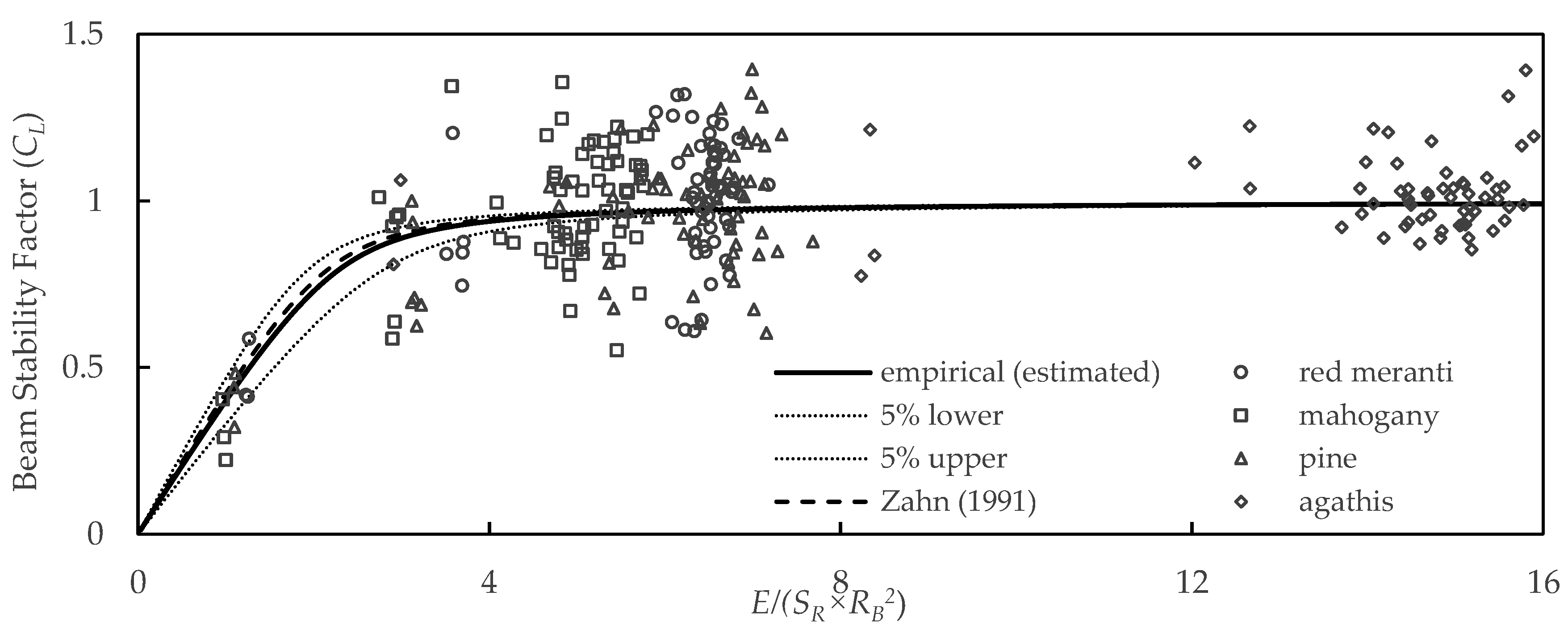
The parameter estimations of non-linear regression analysis under Equation (17) are presented in Table 7, and the best-fit formula is Equation (18). The estimated Euler buckling coefficient (KbE) value obtained in this study was 0.413, with 5% lower and 5% upper values of 0.338 and 0.488. These values were not significantly different from the KbE value proposed by Zahn (KbE = 0.438) [41]. The CL,e value of this experimental study was curve fitted using non-linear estimation (Figure 7). Zahn’s CL curve [41] almost coincides with the estimated empirical CL curve obtained in this study, and is between the 5% lower and 5% upper estimation value of KbE.
C L = 1 + 0 . 413 E S R R B 2   1 . 9 1 + 0 . 413 E S R R B 2   1 . 9 2 0 . 413 E S R R B 2   0 . 95 ,   R 2   = 32.90 %
Multiplying KbE by the factor of 2.74 results in the adjusted Euler buckling coefficient (KbE), for which the value found in this study was 1.13. The obtained KbE in this study was similar to that of the NDS (KbE = 1.20) [35]. The 5% lower and 5% upper values of KbE were 0.92 and 1.33, respectively, which includes the KbE value proposed by the NDS. Because the empirical KbE is similar to that of the NDS, this experimental study approves the NDS CL equation, and we therefore propose to continue using it. The NDS CL equation adopted by SNI 7973:2013 [33] proves reliable for adjusting the reference bending strength of red meranti, mahogany, pines, and agathis sawn lumber.
The obtained KbE values differ among wood species because of the variation of E/SR; thus, the estimated CL formula on all RB ranges from this experiment can be inferred (Figure 8) for each timber species, then compared to the NDS formula. The CL curve positions of red meranti, mahogany, and pine were below that of the NDS, while the CL curve of agathis was above it. Agathis has the highest CL value among the other timbers. The parameter that mostly affects CL value is E/SR. The E/SR value of agathis is the highest due to its low modulus of rupture (SR) value (Table 3). The order of the CL curve positions (Figure 8) proportionally corresponds to the E/SR values. A higher E/SR value means that the CL curve will be in the upper position. The CL value curve of agathis was the highest among the others because the agathis beam did not twist during the bending test; it failed before twisting could occur, indicating inelastic material failure. While red meranti, mahogany, and pine twisted when applying the edgewise mid-point loading bending test, failure occurred when twisting caused the specimen to turn flatwise or slip from the supports, indicating elastic lateral buckling failure. Inelastic failure of the beam happened with small deformation, while elastic member failure was indicated by the long deformation. The deformation value at the yield load is related to the ductility.
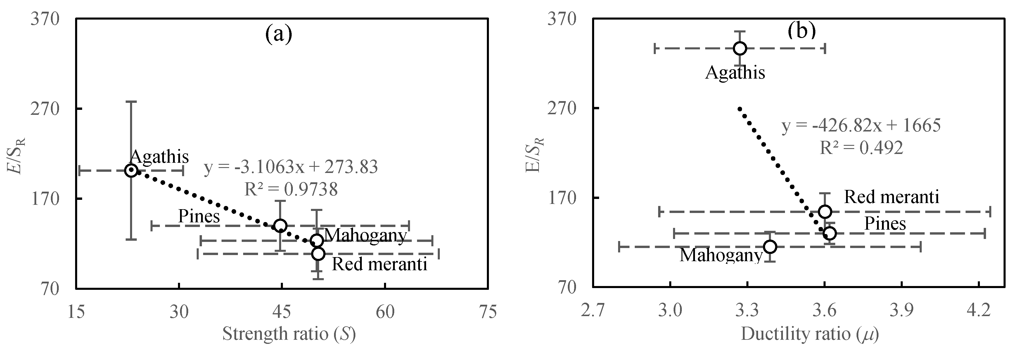
The strength ratio (S) is thought to affect the beam stability factor. The variability of wood mechanical properties is increased in structural timber members due to defects and imperfections (e.g., knots, the slope of the grain, and shakes, checks, and splits) [85]. Agathis contains the most defects among the others, and as such its S value is the lowest. If ascendingly sorted according to their S value, agathis was the lowest, followed by pine, mahogany, and red meranti (Table 5). The order of the S value was inversely proportional to the CL curve position because it is negatively correlated with E/SR (Figure 9a). A lower S value indicates that wood has many defects, in which case the CL curve lies at the upper position. Pelletier and Doudak [86] investigated the lateral–torsional buckling of wood I-joists to account for the effect of the actual end condition and initial imperfection of a beam, and reported that the initial imperfection influences the nonlinear behavior.
Jorrissen and Fragiacomo [57] reported that wooden tension members, most bending members, and most connections are brittle; columns (buckling) and certain connections are semi-ductile, while compression (both parallel and perpendicular to the grain), connection controlled by embedment, and/or steel failure can be categorized as ductile. In this study, the specimens subjected to a mid-point loading test without lateral support (the intermediate beams) mostly experienced twisting before reaching their failure points. Several agathis intermediate beams did not twist until failure. Agathis subjected to bending moment is the most brittle among others, as its ductility ratio (μ) value is the smallest. The failures of the full-size specimens of agathis occurred before twisting, and only a small deformation occurred before failure; thus, agathis subjected to bending can be categorized as brittle. The maximum load of red meranti, mahogany, and pine occurred when they began to twist. The applied load of red meranti, mahogany, and pine decreased as twisting occurred, and the failure load was much lower than the ultimate load. The beams of red meranti, mahogany, and pine can be categorized as low to medium ductile according to Eurocode 8 [74]. The correlation value between μ and E/SR is statistically significant (r = −0.701). Because the ductility value (μ) (Table 5) has a significant inverse correlation to the E/SR value (Figure 9b), it is inversely correlated to the CL value as well. A brittle beam has a higher CL value than a ductile beam. A brittle beam produces only a small deformation, and inelastic failure happens before beam twisting. In contrast, a ductile beam produces significantly larger deformation, and elastic failure commonly occurs.

3.6. Beam Stability Factor (CL) Application in Beam Design

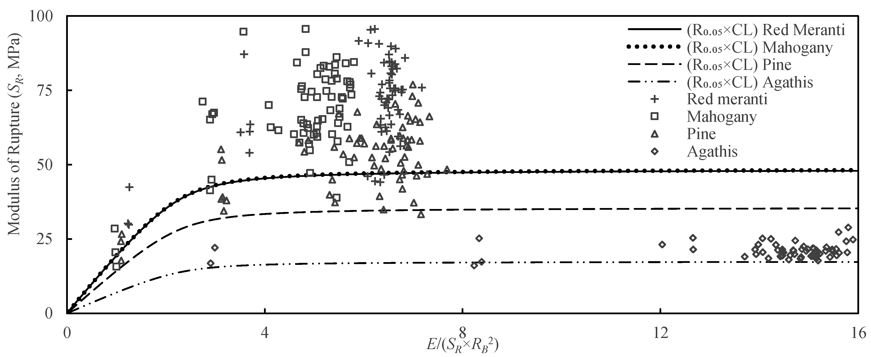
Hayatunnufus reported bending tests of timber short beams with a slenderness ratio of 7.40–7.66, resulted in no twisting [87]. The beam stability factor (CL) is the adjustment factor used to consider the effect of lateral–torsional buckling in intermediate and long beams. CL is applied as a reducing factor for the allowable bending stress (Fb) in combination with the safety factor, load duration factor (CD), wet service factor (CM), temperature (Ct), size factor (CF), flat use factor (Cfu), incising factor (Ci), and repetitive member factor (Cr). The characteristic strength is the 5% exclusion limit (R0.05) value from the experimental result. The result of the R0.05 value of MOR multiplied by CL is presented in Figure 10. As shown in Figure 10, less than 5% of specimens lie below the characteristic strength curve multiplied by CL (R0.05 × CL) (e.g., three red meranti specimens, two mahogany specimens, a pine specimen, and an agathis specimen. Because very few data points lie below the curve, the designer can confidently use the CL value as an adjustment factor for the reference bending design value. The beam stability factor (CL) formula obtained in this study is similar to that of NDS. We suggest that designers continue to use the NDS procedures to adjust the reference bending design value in order to safely and reliably design a beam.

4. Conclusions

The range of sawn lumber beam slenderness ratio in this study was 4.37–11.1, and resulted in an empirical beam stability factor (CL) ranging widely from 0.32 to 1.39. Curve fitting through nonlinear regression resulted in an estimated Euler buckling coefficient (KbE) value of 0.413. By multiplying the factor of 2.74 by KbE, the adjusted KbE value obtained in this study was 1.13, with the 5% lower and 5% upper values of 0.92 and 1.33, respectively, which agrees with that of the NDS (KbE = 1.20). Because agathis has the lowest ductility (μ), most natural defects (smallest strength ratio, S), and highest E/SR ratio among others, the agathis beam did not undergo twisting during the bending test; rather, it failed before twisting could occur, indicating inelastic material failure. Meanwhile the other specimens (pinus, mahogany, and red meranti), which have a smaller E/SR ratio, higher ductility, and fewer natural defects, tended to fail because of their lesser beam stability. This phenomenon resulted in the CL curve of agathis being the highest among others. The CL value mathematically relates to the beam slenderness ratio (RB) and the E/SR ratio. Because the strength ratio (S) and ductility ratio (μ) have significant inverse correlation with the E/SR ratio, they are inversely correlated with the CL value. Applying the CL value to adjust the characteristic bending strength is safe and reliable, as less than 5% of the specimens lay below the characteristic strength curve multiplied by the CL (R0.05 × CL). This study shows that designers can safely apply the CL formula to adjust the red meranti, mahogany, pines, and agathis sawn lumber reference bending design values.

Author Contributions

Conceptualization, E.T.B.; Data curation, E.T.B. and R.H.; Formal analysis, E.T.B. and R.H.; Funding acquisition, E.T.B., D.H. and N.N.; Investigation, E.T.B., E.E. and R.H.; Methodology, E.T.B. and R.H.; Project administration, E.T.B., D.H. and N.N.; Resources, E.T.B.; Supervision, E.T.B. and E.E.; Validation, E.T.B. and R.H.; Visualization, E.T.B. and R.H.; Writing—original draft, E.T.B. and R.H.; Writing—review & editing, E.T.B. All authors have read and agreed to the published version of the manuscript.

Funding

This research was funded by Direktorat Jenderal Pendidikan Tinggi, Riset, dan Teknologi-Kementerian Pendidikan, Kebudayaan, Riset, dan Teknologi-Republik Indonesia grant number 2093/IT.3.L1/PT.01.03/P/B/2022.

Institutional Review Board Statement

This study is not involving humans or animals and the ethical approval is not required.

Informed Consent Statement

Not applicable.

Data Availability Statement

The raw and processed data required to reproduce these findings are available for download from http://dx.doi.org/10.17632/t9k5rh4zy4.3 [88] since 8 January 2021.

Acknowledgments

The authors would like to express many thanks to IPB University (Bogor Agricultural University) (ID), the Ministry of Education and Culture (ID), and the Ministry of Research and Technology (ID) for the finance, permit, facilities, and opportunity to conduct this research.

Conflicts of Interest

The authors declare no conflict of interest.

Abbreviations

aregression coefficient to estimate the KbE
bspecimen width (mm)
cnon-linear parameter for beam = 0.95
CDload duration factor
CFsize factor
Cfuflat use factor
Ciincising factor
Ckbeam stability factor limit
CLbeam stability factor
CLeempirical beam stability factor
CMwet service factor
Crrepetitive member factor
Cttemperature factor
dspecimen depth (mm)
Emodulus of elasticity (MPa)
Emin5% lower exclusion value of modulus elasticity (MPa)
Fbreference bending design value (MPa)
Fbadjusted reference bending design value
FbEcritical buckling design (MPa)
Fuultimate load (N)
Gb specific gravity
KbEEuler buckling coefficient
KbEadjusted Euler buckling coefficient
Lspecimen length (mm)
leeffective span length (mm)
luunsupported length (mm)
m0mass before the bending test (g)
m1mass after the bending test (g)
Mc moisture content (%)
mot mass after oven-drying (g)
R0.055% exclusion limit value
RBbeam slenderness ratio
Rkcharacteristic value (MPa)
Sstrength ratio (%)
SRmodulus of rupture (MPa)
Greek symbol
μductility ratio
Δuultimate displacement (mm)
Δyyield displacement (mm)
ρ density (g/cm3)

References

  1. Lattke, F.; Lehmann, S. Multi-Storey Residential Timber Construction: Current Developments in Europe. J. Green Build. 2007, 2, 119–129. [Google Scholar] [CrossRef]
  2. Buchanan, A.; Deam, B.; Pampanin, S.; Fragiacomo, M.; Palermo, A. Multi-Storey Prestressed Timber Buildings in New Zealand. Struct. Eng. Int. J. Int. Assoc. Bridg. Struct. Eng. 2008, 18, 166–173. [Google Scholar] [CrossRef]
  3. Bahtiar, E.T.; Nugroho, N.; Hermawan, D.; Wirawan, W. Triangle bracing system to reduce the vibration level of cooling tower—Case study in PT Star Energy Geothermal (Wayang Windu) Ltd—Indonesia. Case Stud. Constr. Mater. 2018, 8, 248–257. [Google Scholar] [CrossRef]
  4. Bahtiar, E.T.; Nugroho, N.; Rahman, M.M.; Arinana; Sari, R.K.; Wirawan, W.; Hermawan, D. Estimation the remaining service-lifetime of wooden structure of geothermal cooling tower. Case Stud. Constr. Mater. 2017, 6, 91–102. [Google Scholar] [CrossRef]
  5. Bahtiar, E.T.; Nugroho, N.; Arinana, D.A. Pendugaan Sisa Umur Pakai Kayu Komponen Cooling Tower di Pembangkit Listrik Tenaga Panas Bumi (PLTP) Unit II Kamojang (Estimating the Remaining Life of Wood Cooling Tower Component in Geothermal Power Plant Unit II Kamojang). J. Tek. Sipil. 2012, 19, 103–113. [Google Scholar] [CrossRef]
  6. Lamar, D.M.; Schafer, B.W. Structural Analyses of Two Historic Covered Wooden Bridges. J. Bridg. Eng. 2004, 9, 623–633. [Google Scholar] [CrossRef]
  7. Firmanti, A.; Komatsu, K.; Kawai, S. Effective Utilization of Fast-Growing Acacia mangium Willd. Timber As a Structural Material. J. Trop. Wood Sci. Technol. 2007, 5, 29–37. [Google Scholar]
  8. Firmanti, A.; Bachtiar, E.T.; Surjokusumo, S.; Komatsu, K.; Kawai, S. Mechanical stress grading of tropical timbers without regard to species. J. Wood Sci. 2005, 51, 339–347. [Google Scholar] [CrossRef]
  9. Steffen, A.; Johansson, C.-J.; Wormuth, E.-W. Study of the relationship between flatwise and edgewise modull of elasticity of sawn timber as a means to improve mechanical strength grading technology. Holz als Roh-Werkst. 1997, 55, 245–253. [Google Scholar] [CrossRef]
  10. Oscarsson, J.; Olsson, A.; Enquist, B. Optimization of machine strength grading of structural timber by means of bending MOE profiles with high resolution. In Proceedings of the 18th International Nondestructive Testing and Evaluation of Wood Symposium, Madison, WI, USA, 24−27 September 2013. [Google Scholar]
  11. Bodig, J.; Jayne, B. Mechanics of Wood and Wood Composites; Van Nostrand Reinhold Company: New York, NY, USA, 1982. [Google Scholar]
  12. Bahtiar, E.T.; Malkowska, D.; Trujillo, D.; Nugroho, N. Experimental study on buckling resistance of Guadua angustifolia bamboo column. Eng. Struct. 2020, 228, 111548. [Google Scholar] [CrossRef]
  13. Nugroho, N.; Bahtiar, E.T. Buckling formulas for designing a column with Gigantochloa apus. Case Stud. Constr. Mater. 2021, 14, e00516. [Google Scholar] [CrossRef]
  14. Bahtiar, E.T.; Imanullah, A.P.; Hermawan, D.; Nugroho, N. Structural grading of three sympodial bamboo culms (Hitam, Andong, and Tali) subjected to axial compressive load. Eng. Struct. 2018, 181, 233–245. [Google Scholar] [CrossRef]
  15. Bahtiar, E.T.; Trujillo, D.; Nugroho, N. Compression resistance of short members as the basis for structural grading of Guadua angustifolia. Constr. Build. Mater. 2020, 249, 118759. [Google Scholar] [CrossRef]
  16. American Wood Council. 1997 NDS Commentary; American Wood Council: Leesburg, VA, USA, 1997. [Google Scholar]
  17. Pi, Y.-L.; Bradford, M.A. Thermoelastic lateral-torsional buckling of fixed slender beams under linear temperature gradient. Int. J. Mech. Sci. 2008, 50, 1183–1193. [Google Scholar] [CrossRef]
  18. Hindman, D.P.; Manbeck, H.B.; Janowiak, J.J. Measurement and prediction of lateral torsional buckling loads of composite wood materials: Rectangular sections. For. Prod. J. 2005, 55, 42. [Google Scholar]
  19. Hassan, O.A.; Johansson, C. Glued laminated timber and steel beams. J. Eng. Des. Technol. 2018, 16, 398–417. [Google Scholar] [CrossRef]
  20. ASTM D143; Standard Test Methods for Small Clear Specimens of Timber. ASTM: West Conshohocken, PA, USA, 2002.
  21. Jamil, A.M.; Zamin, J.M.; Omar, M.M. Relationship between mechanical properties of structural size and small clear specimens of timber. J. Trop. For. Sci. 2013, 25, 12–21. [Google Scholar]
  22. Bahtiar, E.T.; Nugroho, N.; Nandika, D. Daily Cycle of Air Temperature and Relative Humidity Effect to Creep Deflection of Wood Component of Low-cost House in Cibeureum-Bogor, West Java, Indonesia. Asian J. Sci. Res. 2014, 7, 501–512. [Google Scholar] [CrossRef]
  23. Bahtiar, E.T.; Nugroho, N.; Surjokusumo, S. Estimating Young’s Modulus and Modulus of Rupture of Coconut Logs using Reconstruction Method. Civ. Eng. Dimens. 2010, 12, 65–72. [Google Scholar] [CrossRef]
  24. BS 373:1957; Methods of Testing Small Clear Specimens of Timber. British Standards: London, UK, 1957.
  25. Bahtiar, E.T.; Nugroho, N.; Karlinasari, L.; Darwis, A.; Surjokusumo, S. Rasio Ikatan Pembuluh sebagai Substitusi Rasio Modulus Elastisitas pada Analisa Layer System pada Bilah Bambu dan Bambu Laminasi. J. Tek. Sipil 2014, 21, 147. [Google Scholar] [CrossRef]
  26. Veldman, S.; Bergsma, O.; Beukers, A. Bending of anisotropic inflated cylindrical beams. Thin-Walled Struct. 2005, 43, 461–475. [Google Scholar] [CrossRef]
  27. Manikandan, P.; Rao, G.S.; Srinath, J.; Sharma, V.; Narayanan, P.R.; Sharma, S.; George, K.M. Axial and Bending Fatigue Testing of AISI 304 L Plumbing Tubes Used for Launch Vehicles Control System. Mater. Sci. Forum 2015, 830–831, 187–190. [Google Scholar] [CrossRef]
  28. Trujillo, D.; Jangra, S.; Gibson, J.M. Flexural properties as a basis for bamboo strength grading. Proc. Inst. Civ. Eng.—Struct. Build 2017, 170, 284–294. [Google Scholar] [CrossRef] [Green Version]
  29. Nurmadina; Nugroho, N.; Bahtiar, E.T. Structural grading of Gigantochloa apus bamboo based on its flexural properties. Constr. Build. Mater. 2017, 157, 1173–1189. [Google Scholar] [CrossRef]
  30. Nugroho, N.; Bahtiar, E.T. Grading Development of Indonesian Bamboo Culm: Case Study on Tali Bamboo (Gigantochloa apus). In Proceedings of the 2018 World Conference on Timber Engineering, Seoul, Korea, 20 August 2018. [Google Scholar]
  31. Saoula, A.; Meftah, S.A.; Mohri, F.; Daya, E.M. Lateral buckling of box beam elements under combined axial and bending loads. J. Constr. Steel Res. 2016, 116, 141–155. [Google Scholar] [CrossRef]
  32. Galambos, T.V.; Surovek, A.E. Structural Stability of Steel; John Wiley & Sons, Inc.: Hoboken, NJ, USA, 2008. [Google Scholar]
  33. SNI 7973:2013; Spesifikasi Desain Untuk Konstruksi Kayu. Badan Standardisasi Nasional: Jakarta, Indonesia, 2013.
  34. Suryoatmono, B.; Tjondro, A. Lateral-torsional buckling of orthotropic rectangular section beams. In Proceedings of the 10th World Conference on Timber Engineering, Miyazaki, Japan, 2–5 June 2008. [Google Scholar]
  35. American National Standard Institution; American Wood Council. NDS, National Design Specification for Wood Construction, ASD/LRFD; American National Standard Institution: Washington, DC, USA, 2012. [Google Scholar]
  36. EN 1995-1-1:2004; Eurocode 5: Design of Timber Structures—Part 1-1: General—Common Rules and Rules for Buildings. The European Union: Brussels, Belgium, 2004.
  37. Zahn, J.J. Design of Wood Members Under Combined Load. J. Struct. Eng. 1986, 112, 2109–2126. [Google Scholar] [CrossRef]
  38. American Wood Council. National Design Specification (NDS) for Wood Construction; American Wood Council: Leesburg, VA, USA, 1986. [Google Scholar]
  39. Zahn, J. Combined-load Stability Criterion for wood-beam columns. J. Struct. Eng. 1988, 114, 22981. [Google Scholar] [CrossRef]
  40. American Forest and Paper Association. ANSI/NFoPA NDS-1991 National Design Specification for Wood Construction; American Forest and Paper Association: Washington, DC, USA, 1991. [Google Scholar]
  41. Zahn, J.J. Biaxial Beam-Column equation for Wood Members. In Proceedings of the 9th structures Congress Proceedings, New York, NY, USA, 29 April–1 May 1991; pp. 56–59. [Google Scholar]
  42. Kimble, R.E.; Bender, D.A. Stability of Built-Up Timber Beams and Columns: Accounting for Modulus of Elasticity Variability. Pr. Period. Struct. Des. Constr. 2010, 15, 272–277. [Google Scholar] [CrossRef]
  43. Du, Y.; Mohareb, M.; Doudak, G. Nonsway Model for Lateral Torsional Buckling of Wooden Beams under Wind Uplift. J. Eng. Mech. 2016, 142, 04016104. [Google Scholar] [CrossRef]
  44. Du, Y.; Mohareb, M.; Doudak, G.; Du, B.Y. Sway Model for the Lateral Torsional Buckling Analysis of Wooden Twin-beam-deck Systems. Structures 2019, 19, 19–29. [Google Scholar] [CrossRef]
  45. Hu, Y.; Mohareb, M.; Doudak, G. Lateral Torsional Buckling of Wooden Beams with Midspan Lateral Bracing Offset from Section Midheight. J. Eng. Mech. 2017, 143, 04017134. [Google Scholar] [CrossRef]
  46. Hu, Y.; Mohareb, M.; Doudak, G. Effect of Eccentric Lateral Bracing Stiffness on Lateral Torsional Buckling Resistance of Wooden Beams. Int. J. Struct. Stab. Dyn. 2018, 18, 1850027. [Google Scholar] [CrossRef]
  47. St-Amour, R.; Doudak, G. Experimental and numerical investigation of lateral torsional buckling of wood I-joists. Can. J. Civ. Eng. 2018, 45, 41–50. [Google Scholar] [CrossRef] [Green Version]
  48. Burow, J.R.; Manbeck, H.B.; Janowiak, J.J. Lateral Stability Considerations for Composite Wood I-Joists. In Proceedings of the ASAE Annual International Meeting, Tampa, FL, USA, 17–20 July 2005. [Google Scholar]
  49. Sahraei, A.; Pezeshky, P.; Mohareb, M.; Doudak, G. Simplified expressions for elastic lateral torsional buckling of wooden beams. Eng. Struct. 2018, 174, 229–241. [Google Scholar] [CrossRef]
  50. Xiao, Q.; Doudak, G.; Mohareb, M. Numerical and experimental investigation of lateral torsional buckling of wood beams. Eng. Struct. 2017, 151, 85–92. [Google Scholar] [CrossRef]
  51. Balaz, I. Lateral Torsional Buckling of Timber Beams. Wood Res. 2005, 50, 51–58. [Google Scholar]
  52. AFPA-TR14; Designing for Lateral-Torsional Stability in Wood Members. American Wood Council: Washington DC, USA, 2003.
  53. ASTM D2915; Standard Practice for Evaluating Allowable Properties for Grades of Structural Lumber. ASTM: West Conshohocken, PA, USA, 2002. [CrossRef]
  54. ASTM D5457; Standard specification for computing reference resistance of wood based materials and structural connections for load and resistance factor design. ASTM: West Conshohocken, PA, USA, 2002.
  55. Blaß, H.J.; Schädle, P. Ductility aspects of reinforced and non-reinforced timber joints. Eng. Struct. 2011, 33, 3018–3026. [Google Scholar] [CrossRef]
  56. Muñoz, W.; Salenikovich, A.; Mohammad, M.; Quenneville, P. Determination of yield point and ductility of timber assemblies: In search for a harmonised approach. In Proceedings of the 10th World Conference on Timber Engineering, Miyazaki, Japan, 2–5 June 2008. [Google Scholar]
  57. Jorissen, A.; Fragiacomo, M. General notes on ductility in timber structures. Eng. Struct. 2011, 33, 2987–2997. [Google Scholar] [CrossRef]
  58. Karacabeyli, E.; Ceccotti, A. Nailed Wood-Frame Shear Walls for Seismic Loads: Test Results and Design Considerations. In Structural Engineering World Wide; SCIRP: Wuhan, China, 1999; pp. 1–9. [Google Scholar]
  59. Yasumura, M.; Kawai, N. Estimating seismic performance of wood-framed structures. In Proceedings of the 5th World Conference on Timber Engineering, Montreux, Switzerland, 17–20 August 1998; Volume 2, pp. 564–571. [Google Scholar]
  60. Foliente, G.C. Issues in seismic performance testing and evaluation of timber structural systems. In Proceedings of the International Wood Engineering Conference, New Orleans, LA, USA, 28–31 October 1996; p. 8. [Google Scholar]
  61. EN 12512:2001/A1:2005; Timber Structures—Test methods—Cyclic Testing of Joints Made with Mechanical Fasteners. European Committee for Standardization: Bruxelles, Belgium, 2005.
  62. SIA 265:2003; Timber Structures. Swiss Society of Engineers and Architects: Zurich, Switzerland, 2003.
  63. Foliente, G.C.; Leicester, R.H. Evaluation of mechanical joint systems in timber structures. In Proceedings of the 25th Forest Products Research Conference, Melbourne, VIC, Australia, 18–21 November 1996; pp. 2–16. [Google Scholar]
  64. ASTM D245; Standard Practice for Establishing Structural Grades and Related Allowable Properties for Visually Graded Lumber. ASTM: West Conshohocken, PA, USA, 2000. [CrossRef]
  65. Bergou, E.H.; Diouane, Y.; Kungurtsev, V. Convergence and Complexity Analysis of a Levenberg–Marquardt Algorithm for Inverse Problems. J. Optim. Theory Appl. 2020, 185, 927–944. [Google Scholar] [CrossRef]
  66. Wistara, N.J.; Sukowati, M.; Pamoengkas, P. The properties of red meranti wood (Shorea leprosula Miq) from stand with thinning and shade free gap treatments. J. Indian Acad. Wood Sci. 2016, 13, 21–32. [Google Scholar] [CrossRef]
  67. Alokabel, K.; Lay, Y.E.; Wonlele, T. Penentuan Kelas Kuat Kayu Lokal di Pulau Timor Sebagai Bahan Konstruksi. JUTEKS J. Tek. Sipil 2018, 2, 139–148. [Google Scholar] [CrossRef]
  68. Lempang, M. Basic properties and uses of agathis (Agathis hamii M. Dr.) wood from South Sulawesi. J. Penelit. Kehutan. Wallacea 2017, 6, 157–167. [Google Scholar] [CrossRef] [Green Version]
  69. NI-5 PKKI 1961; Peraturan Konstruksi Kayu Indonesia. PKKI: Jakarta, Indonesia, 1961.
  70. Ong, C.B.; Ansell, M.P.; Chang, W.-S.; Walker, P. Bending properties of finger-jointed Malaysian dark red meranti. Int. Wood Prod. J. 2019, 10, 49–54. [Google Scholar] [CrossRef]
  71. Anoop, E.V.; Jijeesh, C.M.; Sindhumathi, C.R.; Jayasree, C.E. Wood physical, Anatomical and Mechanical properties of Big Leaf Mahogany (Swietenia macrophylla Roxb) a potential exotic for South India. Res. J. Agric. For. Sci. 2014, 2, 7–13. [Google Scholar]
  72. Darmawan, W.; Nandika, D.; Afaf, B.D.H.; Rahayu, I.; Lumongga, D. Radial Variation in Selected Wood Properties of Indonesian Merkusii Pine. J. Korean Wood Sci. Technol. 2018, 46, 323–337. [Google Scholar] [CrossRef]
  73. Ishiguri, F.; Wahyudi, I.; Iizuka, K.; Yokota, S.; Yoshizawa, N. Radial Variation of Wood Property in Agathis sp. and Pinus insularis Growing at Plantation in Indonesia. Wood Res. J. 2010, 1, 1–6. [Google Scholar]
  74. Eurocode 8; Design of structures for earthquake resistance. European Comission: Brussel, Belgium, 2005.
  75. Szabolcs, K.; Sandor, F.; Jozsef, A.; Taschner, R. Effect of knots on the bending strength and the modulus of elasticity of wood. Wood. Res. 2013, 58, 617–626. [Google Scholar]
  76. Pope, D.; Marcroft, J.; Whale, L. The effect of global slope of grain on the bending strength of scaffold boards. Holz als Roh- Werkst. 2005, 63, 321–326. [Google Scholar] [CrossRef]
  77. Bahtiar, E.T. Keandalan modulus of elasticity (MOE) untuk menduga kekuatan kayu bercacat akibat lubang bor. JTHH 2005, 18, 80–90. [Google Scholar]
  78. Mardikanto, T.R.; Karlinasari, L.; Bahtiar, E.T. Sifat Mekanis Kayu; IPB Press: Bogor, Indonesia, 2017. [Google Scholar]
  79. Rocha, M.F.V.; Costa, L.R.; Costa, L.J.; De Araújo, A.C.C.; Soares, B.C.D.; Hein, P. Wood Knots Influence the Modulus of Elasticity and Resistance to Compression. Floresta e Ambient. 2018, 25, e20170906. [Google Scholar] [CrossRef]
  80. Brunetti, M.; Nocetti, M.; Burato, P. Strength Properties of Chestnut Structural Timber with Wane. Adv. Mater. Res. 2013, 778, 377–384. [Google Scholar] [CrossRef]
  81. Brancheriau, L.; Bailleres, H.; Guitard, D. Comparison between modulus of elasticity values calculated using 3 and 4 point bending tests on wooden samples. Wood Sci. Technol. 2002, 36, 367–383. [Google Scholar] [CrossRef]
  82. Hein, P.R.G.; Silva, J.; Brancheriau, L. Correlations among microfibril angle, density, modulus of elasticity, modulus of rupture and shrinkage in 6-year-old Eucalyptus urophylla × E. grandis. Maderas Cienc Y Tecnol. 2013, 15, 171–182. [Google Scholar] [CrossRef]
  83. Sholadoye, I.O.; Abubakar, I.; Annafi, Q.B.; Ejeh, S.P. Evaluation of Some Wood Properties of Nigeria Timber Using Four-Point Bending Test. Adv. Multidiscip. Res. J. 2016, 2, 133–144. [Google Scholar]
  84. Divos, F.; Tanaka, T. Lumber Strength Estimation by Multiple Regression. Holzforschung 1997, 51, 467–471. [Google Scholar] [CrossRef]
  85. Machado, J.S.; Palma, P. Non-destructive evaluation of the bending behaviour of in-service pine timber structural elements. Mater. Struct. 2010, 44, 901–910. [Google Scholar] [CrossRef]
  86. Pelletier, B.; Doudak, G. Investigation of the lateral-torsional buckling behaviour of engineered wood I-joists with varying end conditions. Eng. Struct. 2019, 187, 329–340. [Google Scholar] [CrossRef] [Green Version]
  87. Hayatunnufus, A.; Nugroho, N.; Bahtiar, E.T. Faktor Stabilitas Balok Kayu pada Konfigurasi Pembebanan Terpusat. J. Tek. Sipil dan Lingkung. 2022, 7, 129–146. [Google Scholar] [CrossRef]
  88. Bahtiar, E.T. Experimental Study on Flexural Buckling of Timber, Mendeley Data V3; Elsevier Inc.: NY, USA, 2020. [Google Scholar] [CrossRef]
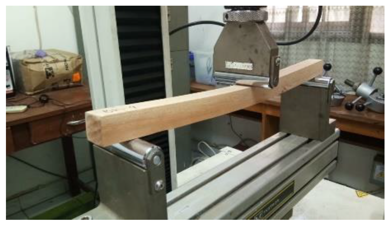
Figure 1. Static bending test of small specimens following the ASTM D143 secondary method [20]. The specimen size was 25 × 25 × 410 mm with the span length of 360 mm and loading speed of 1.3 mm/min.
Forests 13 01480 g001
Figure 2. Measurement of defects and imperfections to calculate the strength ratio value (S) of bending following ASTM D245 [64]: (a) the slope of the grain was measured by the tangent of the angle between the direction of the fibers and the edge of the specimen; (b) knots at the wide face were measured by the average of their largest and smallest diameter; (c) knots at the narrow face were measured by their width between the lines enclosing the knot and parallel to the edges of the specimen; and (d) shakes, checks, and splits were measured at the ends of the specimen.
Forests 13 01480 g002
Figure 3. Scheme of a single-span beam subjected to concentrated loads at several points: (a) center-point loading without lateral support, (b) center-point loading, (c) third point loading, (d) fourth point loading, (e) fifth point loading, (f) sixth point loading (Note: P = applied load; L = span; ↔ = lateral support; Forests 13 01480 i001 = LVDT).
Forests 13 01480 g003
Figure 4. (a) Air-dry moisture content (Mc); (b) density (ρ) and specific gravity (Gb).
Forests 13 01480 g004
Figure 5. The bending test load–displacement curve: (a) red meranti, (b) mahogany, (c) pine, and (d) agathis. (Note: each graph consists of five specimens which were selected randomly from 50 specimens).
Forests 13 01480 g005
Figure 6. Flexural properties (a) modulus of elasticity (E) and (b) modulus of rupture (SR) of full-size specimens subjected to various concentrated loads (Note: control = center-point loading without lateral support; 1/2 point = center-point with lateral support; 1/3 point = third point with lateral support; 1/4 point = fourth point with lateral support; 1/5 point = fifth point with lateral support; 1/6 point = sixth point with lateral support).
Forests 13 01480 g006
Figure 7. Nonlinear estimation of the empirical beam stability factor (CL,e) curve compared to Zahn’s CL curve [41] (Note: Modulus of elasticity (E) and modulus of rupture (SR) on abscissa were obtained from the average value of the small specimen bending tests).
Forests 13 01480 g007
Figure 8. The experimental beam stability factor (CL) curve applicable to all slenderness ratios (RB) of each timber species and all specimens as compared to the NDS’s curve.
Forests 13 01480 g008
Figure 9. Correlation between the strength ratio (S) and E/SR of the small specimen (a) and between the ductility ratio (μ) and E/SR of the full-size specimen (b). Both strength ratio (S) and ductility ratio (μ) are negatively correlated with E/SR.
Forests 13 01480 g009
Figure 10. Experimental result of modulus of rupture (SR) compared to the characteristic strength multiplied by the beam stability factor (R0.05 × CL) (Note: E and SR on abscissa are the average value of the small-size specimen).
Forests 13 01480 g010
Table 1. The simply supported beam bending formula.
Loading ConfigurationBending Formula
center-point loading with or without lateral support E = P L 3 4 Δ bd 3 S R = 3 P max L 2 bd   2
third point loading with lateral supports E = 23 P L 3 108 Δ bd 3 S R = P max L bd   2  
fourth point loading with lateral supports E = 19 P L 3 96 Δ bd 3   S R = P max L bd   2
fifth point loading with lateral supports E = 9 P L 3 50 Δ bd 3 S R = 9 P max L 10 bd   2
sixth point loading with lateral supports E = 11 P L 3 60 Δ bd 3 S R = 9 P max L 10 bd   2
Note: Pmax = maximum load borne by beam or column loaded to failure (N), P = increment of applied load below the proportional limit (N), L = span of a beam (mm), ∆ = increment of deflection of beam’s neutral axis measured at midspan over distance L and corresponding load P (mm), b = width of beam (mm), d = depth of beam (mm).
Table 2. Effective span length (le) for bending members.
NoSingle Span BeamEffective Span Length (le)
lu/d < 7lu/d ≥ 7
1. center-point loading without lateral supportle = 1.8 lule = 1.37 lu + 3d
2. center-point loading with lateral supportle = 1.11 lu
3. third point loading with lateral supportsle = 1.68 lu
4. fourth point loading with lateral supportsle = 1.54 lu
5. fifth point loading with lateral supportsle = 1.68 lu
6. sixth point loading with lateral supportsle = 1.73 lu
Note: le is effective span length for bending members (mm), lu is the distance between such points of intermediate lateral support (mm).
Table 3. The small specimens’ flexural properties.
Modulus of Elasticity (E, MPa)Modulus of Rupture (SR, MPa) E S R
nMinMaxMeansCV (%)MinMaxMeansCV (%)
Red meranti5083461387911001137912.5444.0790.8772.4212.1516.77151.91
Mahogany505275103938033107913.4338.8394.6970.4711.3716.14113.99
Pine503460106957218183725.4528.8776.8755.1510.1818.46130.88
Agathis506020860469766188.8517.7125.0320.591.587.67336.21
Table 4. The estimated population parameter of the small specimens’ flexural properties.
Timber SpeciesRed Meranti MahoganyPineAgathis
ParameterESRESRESRESR
WeibullAD = 0.467
p = 0.244
AD = 0.291
p > 0.250
AD = 0.256
p > 0.250
AD = 0.544
p = 0.172
AD = 0.191
p > 0.250
AD = 0.476
p > 0.250
AD = 1.675
p < 0.010
AD = 2.561
p < 0.010
5% PE834648.37594948.56393635.60578417.44
LognormalAD = 0.916
p = 0.018
AD = 1.400
p < 0.005
AD = 0.627
p = 0.097
AD = 0.291
p = 0.053
AD = 0.731
p = 0.093
AD = 1.114
p = 0.006
AD = 0.547
p = 0.151
AD = 0.630
p = 0.095
5% PE843549.24599349.25400936.09584317.65
5% TL (75%)865351.08616450.97423537.57594517.92
NormalAD = 0.684
p = 0.070
AD = 0.665
p = 0.078
AD = 0.270
p = 0.663
AD = 0.561
p = 0.139
AD = 0.199
p = 0.880
AD = 0.476
p = 0.229
AD = 0.760
p = 0.045
AD = 0.941
p = 0.016
Mean1100272.42803370.47721855.15697727.28
s137912.15107911.37183710.186181.58
5% PE822848.00586447.60352434.68573524.11
5% TL (75%)850450.42608049.87389136.71585824.42
Non-Parametric
5% PE873545.22567050.96394034.08616418.25
5% TL (75%)834744.07527638.83346028.87602017.71
Note: PE = point estimate, TL = tolerance limit, s = standard deviation, AD = Anderson-Darling, p = probability; best fit estimation parameters are displayed in bold.
Table 5. The small timber beams’ ductility ratio (μ).
NMinMaxMeanSCV (%)
Red meranti502.25.03.60.617.9
Mahogany502.35.03.40.617.3
Pine502.15.33.60.616.7
Agathis502.64.03.30.310.1
Note: μ ≤ 4 = low ductility, 4 ≤ μ ≤ 6 = medium ductility, μ ≥ 6 = high ductility (Eurocode 8 [74]).
Table 6. The full-size specimens’ strength ratio (S).
Timber SpeciesPropertiesNMinMaxMeanSCV (%)
Red merantiS due to slope of grain (%)1840.0084.5060.6214.8524.49
S due to knots (%)1849.00100.0087.5814.7716.87
S due to shakes, checks, splits (%)1850.00100.0094.4416.1717.12
S total value (%)1816.8084.5050.2717.5634.94
MahoganyS due to slope of grain (%)1840.00100.0067.0116.9825.33
S due to knots (%)1862.00100.0073.3610.3414.09
S due to shakes, checks, splits (%)1862.50100.0077.9611.2714.45
S total value (%)1825.5874.5750.0316.8733.72
PineS due to slope of grain (%)1840.0092.5068.2612.2918.00
S due to knots (%)1873.6796.2588.717.508.45
S due to shakes, checks, splits (%)1850.00100.0083.3324.2529.10
S total value (%)1814.7475.5044.7418.7541.91
AgathisS due to slope of grain (%)1840.0045.9840.401.423.53
S due to knots (%)1837.83100.0056.8918.1731.95
S due to shakes, checks, splits (%)18100.00100.00100.000.000.00
S total value (%)1815.1340.0023.037.5632.80
Table 7. Parameter estimation of the Euler buckling coefficient (KbE).
ParameterEstimateStandard Errort-Valuep-ValueLower Confident LimitUpper Confident Limit
aKbE0.4130.03810.8520.000.3380.488
Publisher’s Note: MDPI stays neutral with regard to jurisdictional claims in published maps and institutional affiliations.