Article

Data Fusion Modeling for an RT3102 and Dewetron System Application in Hybrid Vehicle Stability Testing

by
Zhibin Miao
1,2,*,† and
Hongtian Zhang
1,2,†
1
College of Power and Energy Engineering, Harbin Engineering University, Harbin 150001, China
2
Heilongjiang Institute of Technology, Harbin 150050, China
*
Author to whom correspondence should be addressed.
These authors contributed equally to this work.
Algorithms 2015, 8(3), 632-644; https://doi.org/10.3390/a8030632
Submission received: 12 June 2015 / Accepted: 7 August 2015 / Published: 12 August 2015
(This article belongs to the Special Issue Machine Learning Algorithms for Big Data)

Abstract

:
More and more hybrid electric vehicles are driven since they offer such advantages as energy savings and better active safety performance. Hybrid vehicles have two or more power driving systems and frequently switch working condition, so controlling stability is very important. In this work, a two-stage Kalman algorithm method is used to fuse data in hybrid vehicle stability testing. First, the RT3102 navigation system and Dewetron system are introduced. Second, a modeling of data fusion is proposed based on the Kalman filter. Then, this modeling is simulated and tested on a sample vehicle, using Carsim and Simulink software to test the results. The results showed the merits of this modeling.

1. Introduction

Hybrid electric vehicles have been widely accepted by the industry and the market as green vehicles with fewer emissions [1]. There are some advantages in energy savings and clean transporting. Some research data show that hybrid electric vehicles can mean energy savings of more than 30% and can reduce CO2 emissions by 15%, compared to traditional vehicles [2]. Energy efficiency can be further improved in the hybrid electric vehicle power train for EVs using in-wheel motors, since there are no mechanical transmission, differential or redundant drive shafts [3]. Moreover, with in-wheel motors, the total torque demand can be distributed to each wheel independently. Intelligent methods for optimal torque distribution are capable of savings of more than 20% in energy consumption. In addition, flexible regenerative braking algorithms with in-wheel motors could further enhance the energy efficiency of EVs [4]. In this regard, consistently improving the performance of EVs equipped with in-wheel motors by applying novel control methods is still very critical and necessary for saving energy and providing clean transportation. The method can decrease traffic accidents and reduce casualties and economic loss [5].
In a vehicle stability measurement system, GPS can be used to detect performance. It can also be used as a sensor to provide real-time information for a vehicle dynamics stability control system [6]. Now, GPS has been applied in vehicle dynamics stability testing instruments, but the study of the GPS/INS combination for the vehicle stability test remains to be improved [7].
There are strong complementarities between GPS and INS. GPS has some disadvantages [8]. For example, a receiver antenna may be blocked temporarily or it may lose position data due to a signal interruption. INS can provide position, velocity and azimuth information without an external reference resource, but the system has accumulated error. It cannot give high-accuracy positioning information for a long time because of gyroscope drift error [9]. Errors of INS are mainly random drift errors, which cannot be compensated. GPS has such advantages as high positioning accuracy and no accumulated error. The two kinds of systems, used in combination, can compensate for each other and give full play to their strengths [10]. GPS measurement is stable, but the refresh rate (1–10 Hz) is relatively low. The GPS/INS integrated navigation system is a kind of composite that has unique advantages in terms of autonomy and bandwidth frequency. The Kalman filter is commonly used to fuse GPS/INS data [11].
Rodger [12] has done exploratory studies in reducing failure risk in an integrated vehicle health maintenance system using a fuzzy multi-sensor data fusion Kalman filter approach for IVHMS (integrated vehicle health maintenance system). Bevly et al. [9] at American University estimated three key vehicle parameters, such as the tire-slip ratio, sideslip angle and tire sideslip angle based on the GPS speed measuring method. They used the combination between the GPS speed sensor and the high frequency inertial measurement unit (low update rate accelerometer). A tire cornering stiffness update algorithm was used to improve the Kalman filter. They provided an accurate estimation of vehicle state parameters. In Canada, the Center of Mobile Multisensor Research at Calgary University studied how to suppress the errors and to improve precision in detail [13]. They introduced a navigation system with a velocity update scheme that could predict and reduce the error accumulation when there is a loss in GPS signals. Ryu et al. [14] at Stanford University proposed a method to estimate the key parameters of vehicle stability, based on the fusion of vehicle-grade inertial sensors and the GPS receiver. The method can improve the accuracy of estimation for vehicle state parameters considering the influence of pitch and roll, as well as sensor bias errors.
Vehicle sideslip angle and yaw rate are two important parameters for vehicle stability [15]. The vehicle sideslip angle is the angle between the longitudinal axes of the automobile body and the automobile speed direction [16]. However, nowadays, the sideslip angle cannot be measured directly. This is one of the biggest problems for the current development of a vehicle stability control system. Therefore, it is the premise and key technology of vehicle dynamic stability control to measure accurately the actual vehicle side slip angle and yaw rate [17]. The gyro can measure the yaw rate, but there is no suitable equipment for directly measuring the vehicle sideslip angle. Estimation methods are used to get the sideslip angle. These methods are usually combined with the use of the yaw rate gyro and lateral acceleration sensor. However, these sensors usually contain a bias and noise [18]. In addition, a lateral accelerometer cannot provide a good identification of vehicle lateral acceleration and the gravity component of acceleration. The errors of these sensors will be accumulated and even diverge, when the integral is applied [19]. Therefore, errors affect the performance of the vehicle stability control system. However, the application of GPS and INS (inertial navigation system, including the gyroscope and accelerometer) can directly measure the vehicle side slip angle. GPS is the Global Positioning System. DGPS (Differential Globe Positioning System) is a kind of GPS attached to the normal differential correction signal, improving data precision to the millimeter level after processing [20].

2. Experiment Equipment

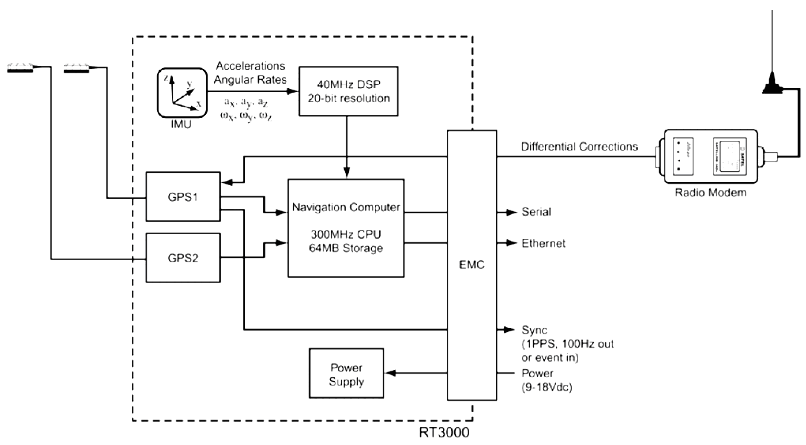
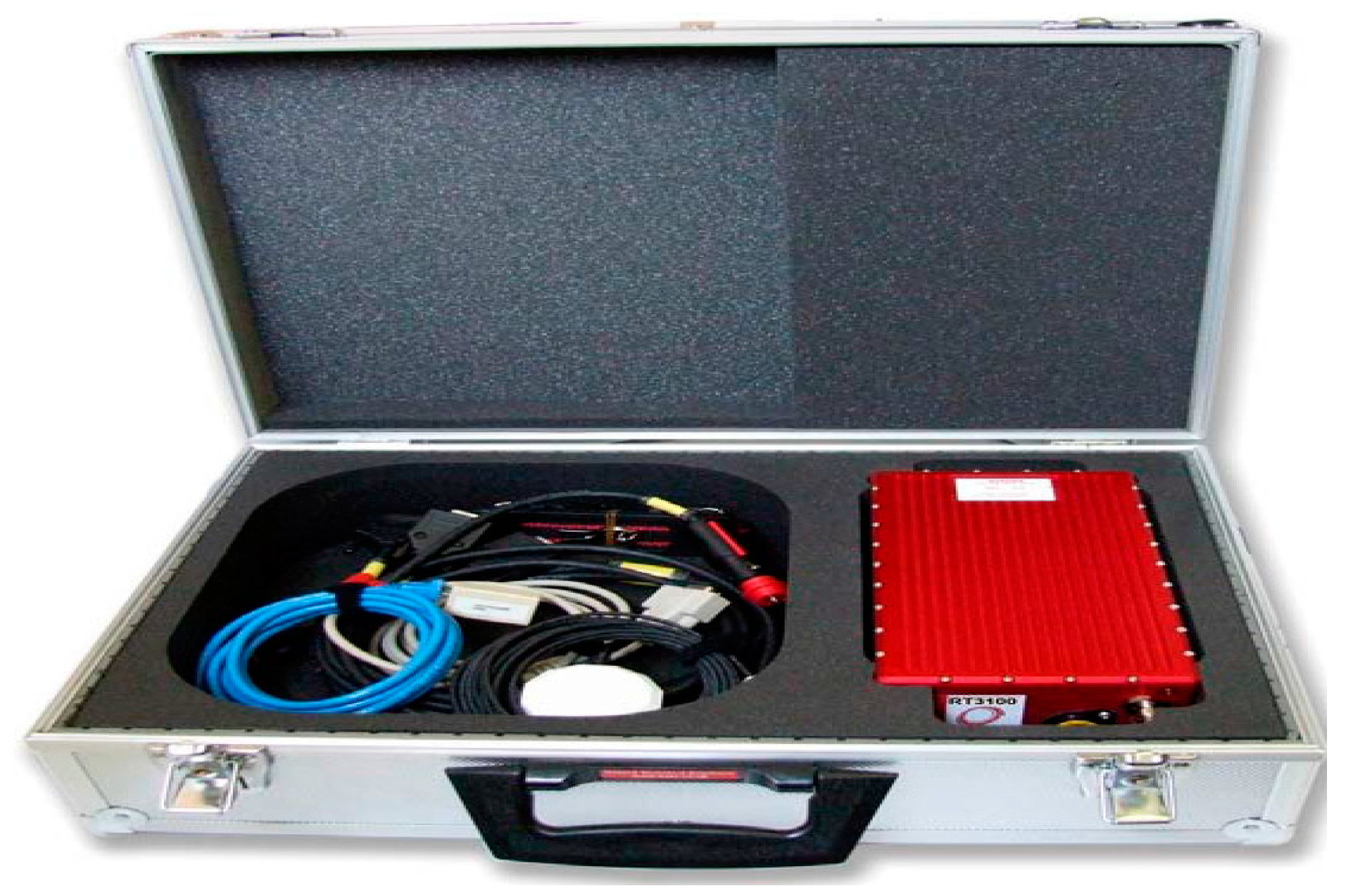
2.1. RT Navigation System

The real time (RT) navigation system of inertial and GPS navigation systems from Oxford Technical Solutions are instruments for making precision measurements of motion in real time [21]. Figure 1 is the RT3102 navigation system.
Figure 1. RT3102 navigation system.
Algorithms 08 00632 g001
To obtain high-precision measurements, the RT uses mathematical algorithms developed for use in fighter aircraft navigation systems. An inertial sensor block with three accelerometers and three gyros (angular rate sensors) is used to compute all of the outputs. A WGS 84 modeled strapdown navigator algorithm compensates for earth curvature, rotation and Coriolis accelerations, while measurements from high-grade kinematic GPS receivers update the position and velocity navigated by the inertial sensors. Figure 2 shows the schematic of the RT internal components. where PPS is Pulses Per Second, DSP is Digital Signal Processor, EMC is External Memory Controller.
This innovative approach gives the RT several distinct advantages over systems that use GPS alone. The RT has a high (100 Hz or 250 Hz) update rate and a wide bandwidth. The outputs are available with very low, 3.5 ms latency. All outputs remain available continuously during GPS blackouts, when, for example, the vehicle drives under a bridge. The RT recognizes jumps in the GPS position and ignores them. The position and velocity measurements that the GPS makes are smoothed to reduce the high-frequency noise. The RT makes many measurements that the GPS cannot make, for example acceleration, angular rate, heading, pitch and roll. The RT takes inputs from a wheel speed sensor in order to improve the drift rate when no GPS is available.
Figure 2. Schematic of the real time RT internal components.
Algorithms 08 00632 g002
The outputs of the system are derived directly from the strapdown navigator. The role of the strapdown navigator is to convert the measurements from the accelerometers and angular rate sensors to position. Velocity and orientation are also tracked and output by the strapdown navigator. Figure 3 shows a basic overview of the strapdown navigator in the RT3201 navigation system. Much of the detail has been left out, and only the key elements are shown here.
Figure 3. Schematic of the strapdown navigator.
Algorithms 08 00632 g003

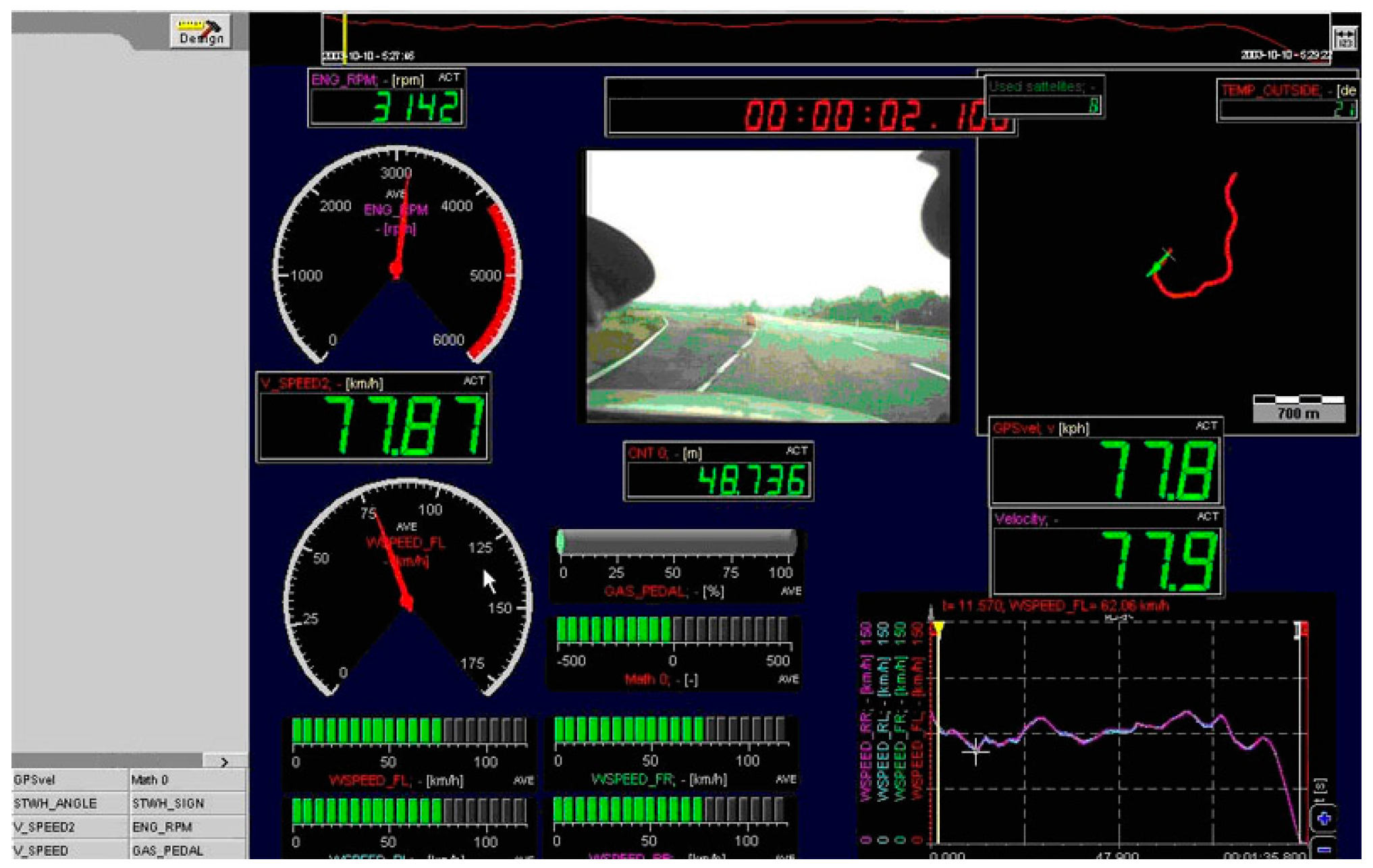
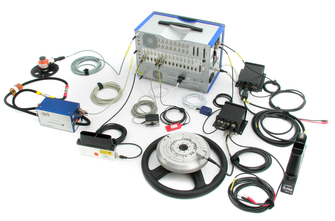
2.2. Dewetron System

Not only can the Dewetron system accurately complete the automobile dynamic performance test according to international standards, it also can complete the dynamic and economic performance test, the ride comfort test, the handling and stability test and the braking performance test according to automotive product development [22]. The vehicle speed and distance sensors, which are based on global satellite positioning technology can not only measure vehicle speed and distance, but also can obtain vehicle test location data and walking track data. Therefore, the system can provide an important means for vehicles dynamic testing and analysis. The system can capture the video signal and select the Controller Area Network Bus (CANBUS) data acquisition module when it collects data. The graphical interface can be set according to the test contents and personal preferences, as shown in Figure 4.
Figure 4. Graphical interface of the Dewetron testing system.
Algorithms 08 00632 g004
Test data can be saved and printed for laboratory analysis. The following is the overall system characteristics: 32 analog channels (16 ICP (internal electronics piezoelectric)/voltage input channels, 16 strain/voltage input channels); 8 counter input channels (for wheel speed sensor or engine speed frequency input); 8 digital I/O; 2 high-speed CAN-bus interfaces (for the temperature module); 32 G flash memory (expandable to 64 G), which is very suitable for a test in a serious vibration environment.
The system can work in various ways independently or work by connecting a notebook computer. The system vibration characteristics meet the EN 60068-2-6 standard and the EN 60721-3-2 2M2 standard. Electromagnetic interference resistance can meet CE standards. Therefore, it is fully applicable to the automobile road test environment. A unique variety signal conditioning module can be suitable for all kinds of sensors, which improves the test accuracy and the system reliability. The software operating system is Windows XP; the data acquisition and analysis system is DEWESOFT-6-Prof and FLEXPRO-8-Prof DataView. The connection diagram for testing system sensors is shown in Figure 5.
Figure 5. Connections for the Dewetron testing system.
Algorithms 08 00632 g005
According to the special requirements of the vehicle performance test, the data acquisition and analysis system should have high impact resistance, vibration resistance, resistance to electromagnetic interference and other characteristics. The vehicle test data acquisition and analysis system is a compact structure design. A modular signal conditioning module, a data acquisition board and an arithmetic processing are integrated into one system, so the sensor and the data acquisition system can become one system. The system has traditional instrument accuracy, and the virtual instrument system has convenient and flexible characteristics.
This software is an integration of multiple functions, including system parameter settings, a data recorder, an x/y axis oscilloscope, a spectrum analyzer, an octave analyzer, a programmable operational virtual channel, video recorders, an integrated signal display instrument, and so on. The system parameter settings include channel selection, range selection, filtering, sampling frequency setting, sensor parameter setting, calibration of the sensor, offset zero sensor, and so on.
The data recorder function includes real-time displaying of measured values or the mean square value and the average value; simultaneously opening multiple display windows, each window is able to be displayed in 1–4 channels. The oscilloscope function can simultaneously open multiple display windows, and each window can be displayed in 1–8 channels by a trigger mode. The X/Y recorder can display one or more channels for measurement testing.

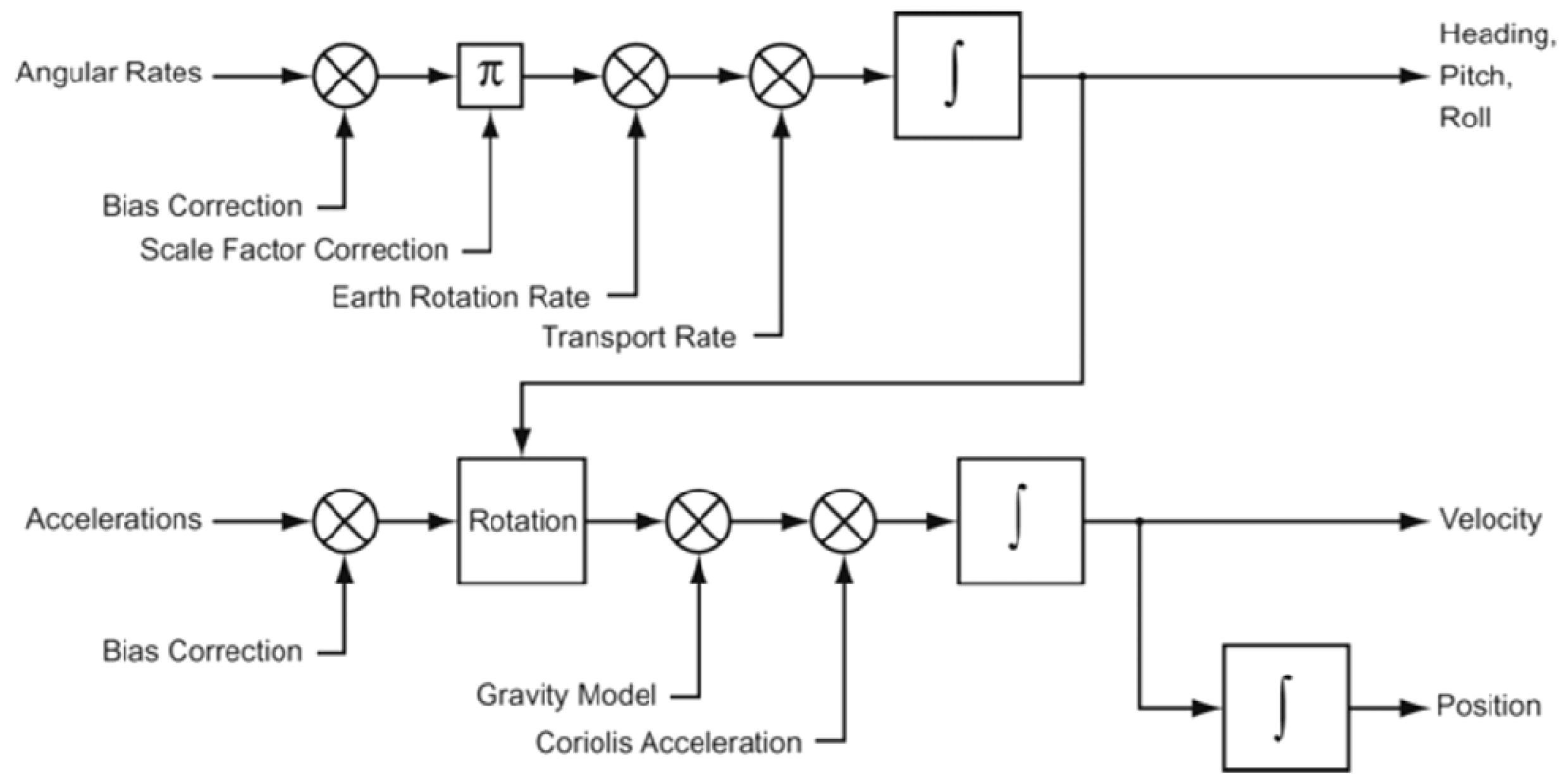
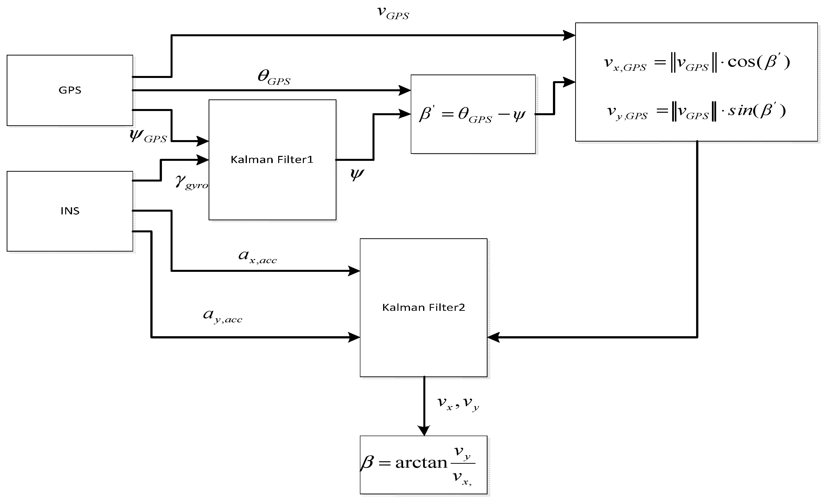
3. Modeling of Data Fusion Algorithm
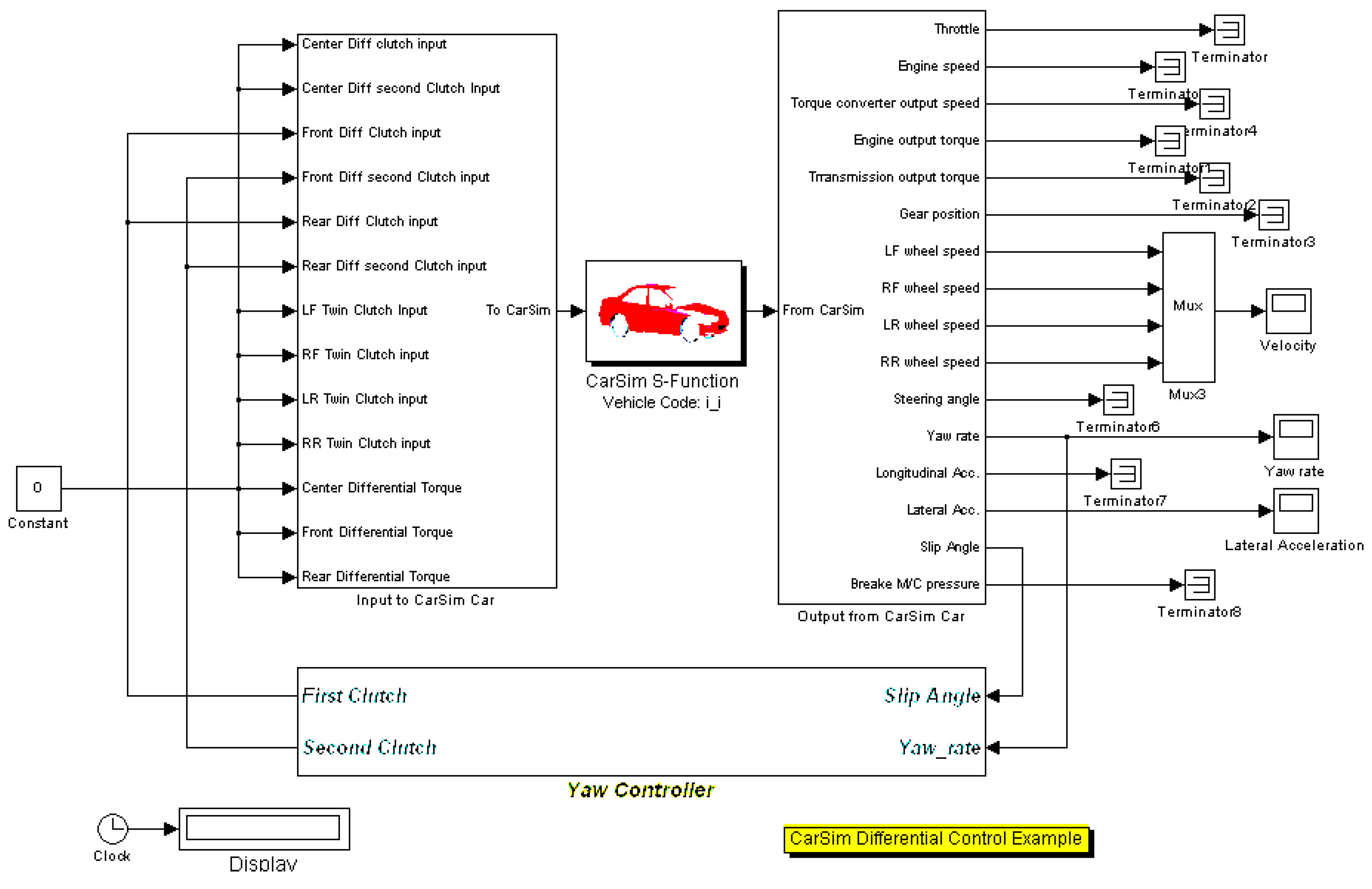
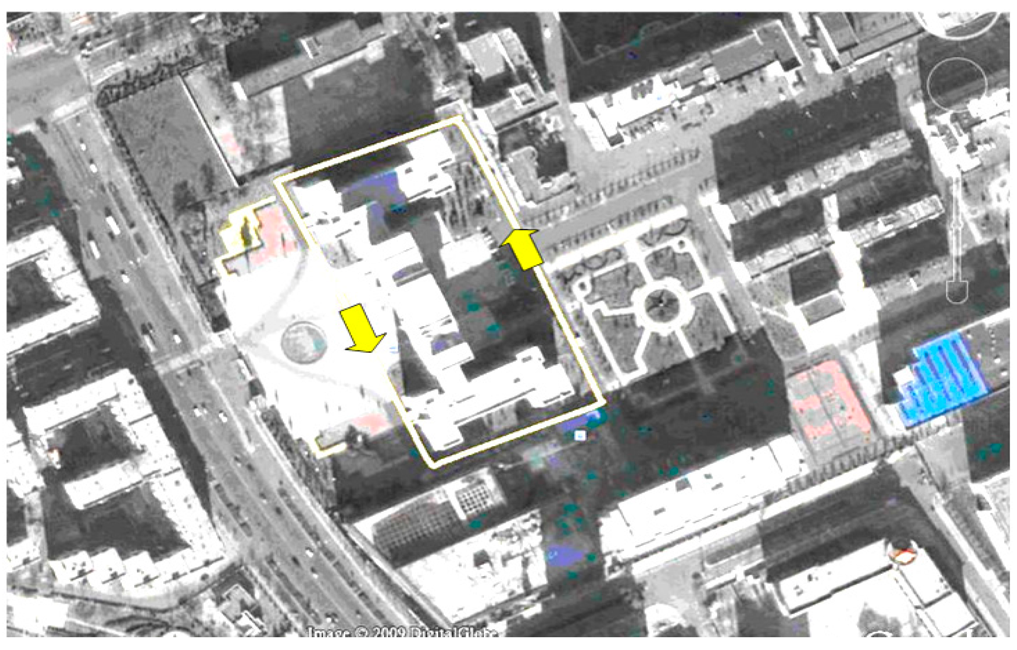
In this work, the data fusion modeling is built using the Kalman algorithm. The Kalman filter is suitable for data fusing [23]. The Kalman filter is a kind of linear filtering recursive algorithm for a discrete signal. For a discrete system:
x ( k ) = A ( k ) x ( k 1 ) + B ( k ) u ( k 1 ) + w ( k )
y ( k ) = H ( k ) x ( k ) + v ( k )
x ( k ) is the system state vector. y ( k ) is the system observation vector. u ( k ) is the system input vector. A ( k ) is the n × n system state matrix. H ( k ) is the m × n system observation matrix. B ( k ) is the 1 × n system input matrix. w ( k ) is the process noise vector. v ( k ) is the observation noise vector.
Assumptions w ( k ) and v ( k ) were independent, and the noise is normal distribution white noise, so w ( k ) and v ( k ) is expressed as the following:
E [ w ( n ) w T ( k ) ] = { Q ( k ) 0 n = k n k
E [ v ( n ) v T ( k ) ] = { R ( k ) 0 n = k n k
E [ w ( n ) v T ( k ) ] = 0
where Q ( k ) is the noise covariance matrix and R ( k ) is the observation noise covariance matrix.
The first step of the Kalman filter is predicting the next state of the system. If the system state is x ( k ) , then the next time system state is:
x ( k + 1 | k ) = A x ( k | k ) + B ( k ) u ( k )
The update status covariance matrix is:
P ( k + 1 | k ) = A ( k ) P ( k | k ) A T ( k ) + Q ( k )
The state at k + 1 time is:
x ( k + 1 | k + 1 ) = x ( k + 1 | k ) + K g ( k ) [ y ( k + 1 ) H ( k ) x ( k + 1 | k ) ]
where K g ( k ) is the Kalman gain:
K g ( k ) = P ( k + 1 | k ) H T ( k ) H ( k ) P ( k + 1 | k ) H T ( k ) + R ( k )
P ( k + 1 | k + 1 ) = [ I K g ( k ) H ( k ) ] P ( k + 1 | k )
The Kalman filter estimation algorithm has five formulas. If giving the initial value of state x ( 0 ) and state covariance matrix P ( 0 ) , the system state can gradually be estimated by the recursive method.
The vehicle side slip angle fusion algorithm based on GPS/INS is shown in Figure 6. The main parameters in GPS measurement are heading angle ψ G P S , azimuth angle θ G P S and speed v G P S , and the main parameters of INS measurement are yaw rate γ g y r o , longitudinal acceleration a x , a c c and lateral acceleration a y , a c c .
Figure 6. Sideslip angle combination algorithm block.
Algorithms 08 00632 g006
GPS and INS combination methods can be divided into the kinematics method and the dynamics method. The kinematics method is based on the motion relations of a car, and it does not rely on the estimation vehicle dynamics model. Because there is no model error, measurement accuracy depends on the accuracy of the testing device and the installation position, so this method is very robust [24].

4. Application

To demonstrate the advantages of this system, it is applied to real car stability testing. This test is based on a computer simulation. The part control structure of Simulink in MATLAB is shown in Figure 7. Carsim is also used in this computer simulation.
Figure 7. Simulink diagram.
Algorithms 08 00632 g007
The real vehicle stability test was performed at the Heilongjiang Institution of Technology campus. The route of the vehicle is a square shape. The car runs around a big building. Therefore, the GPS signal is not stable, and the GPS navigation system is not very precise. The GPS/INS integration navigation system can overcome the shortcomings of GPS in a city. Figure 8 shows the course of the test car. Figure 9 is the picture of the test car and the equipment of the testing system.
Figure 8. Testing course.
Algorithms 08 00632 g008
This work uses the HV2 dual antenna dual function GPS receiver [25]. HV2 can provide accurate directions, with the GPS positioning accuracy up to the sub-meter level, a 0.1 degrees heading precision and a 20 Hz data update rate. In this paper, the INDAS-5000 embedded system is the data acquisition system. INDAS-5000 is on a printed circuit board (PCB) integrated real-time embedded processor, a field programmable gate array (FPGA) and an analog and digital I/O.
The RT3102 is put in a hybrid electric vehicle, and the double antennas are set at the top of the vehicle (shown in Figure 9). The vehicle sideslip angle measured by RT3102 is shown in Figure 10. The vehicle sideslip angle curve are shown in Figure 11.
Figure 9. Testing car and system.
Algorithms 08 00632 g009
Figure 10. Measurement of the hybrid electric vehicle with RT3012.
Algorithms 08 00632 g010
Figure 11. Sideslip angle curve.
Algorithms 08 00632 g011
Kalman filters can be used to merge several measurements of a quantity and, therefore, give a better overall measurement. This is the case with the position and velocity in the RT; the Kalman filter is used to improve the position measurement made from two sources, the inertial sensors and GPS.
The vehicle sideslip angle measured by GPS/INS, which is fused by a two-stage Kalman filter, is shown in Figure 12. From Figure 12, it can be seen that the vehicle sideslip angle is smoother after the Kalman filter algorithm.
Figure 12. Sideslip angle curve.
Algorithms 08 00632 g012
In Figure 13, the vehicle sideslip angle, which is measured by the RT3102 navigation system sensor calibrates the sideslip angle measured by the GPS/INS. Although the curves are similar, the sideslip angle measured by the RT3102 navigation system has great precision. The testing error is small.
Figure 13. Comparison of the sideslip angle curves.
Algorithms 08 00632 g013
From the experimental data, it can be seen that using the Kalman filter algorithm, especially the second order Kalman filter can solve the problem of the GPS signal loss well, and the INS signal accumulation error becomes large during vehicle stability testing. This method can meet the real-time and accuracy requirements for the measurement of the vehicle stability key parameters well.

5. Conclusions

Acquisition of vehicle driving state parameters, which is required for vehicle stability control, is the premise and key technology of the vehicle stability control. In response to the need for hybrid vehicle stability critical state parameter testing, being in real-time and accuracy are the goal. This paper presents a modeling method for vehicle stability testing based on the Kalman algorithm for GPS/INS data fusion. Based on the RT3102 and Dewetron system measurement equipment, a testing method for sideslip angle, speed and vehicle state parameter measurement and estimation is used. The second order Kalman filter can solve the problem of the GPS signal loss well, and INS signal accumulation error becomes large during vehicle stability testing. The simulation and test results showed that the modeling method of the Kalman data fusion is accurate, and this method can meet the real-time and accuracy requirements for the measurement of the vehicle stability key parameters well.

Acknowledgments

The Department of Education of Heilongjiang and China Association for Science and Technology provided the financial support for this work. This work is supported by the Research Projects under the Department of Education of Heilongjiang Grant No. 12511453 and the Overseas Research and Development Program under Grant No. 10027.

Author Contributions

Zhibin Miao conceived and designed the experiments; Zhibin Miao performed the experiments; Zhibin Miao and Hongtian Zhang analyzed the data; Zhibin Miao contributed reagents/materials/analysis tools; Zhibin Miao and Hongtian Zhang wrote the paper.

Conflicts of Interest

The authors declare no conflict of interest.

References

  1. Zeng, L.H.; Li, G.M. World Expo 2010 promotes the reduction in carbon emissions of urban transport. In Proceedings of the 2013 2nd International Conference on Sustainable Energy and Environmental Engineering, ICSEEE 2013, Shenzhen, China, 28–29 December 2013; Volume 525.
  2. Huang, C.; Chen, L.; Jiang, H.B.; Yuan, C.C.; Xia, T. Nonlinear analysis and intelligent control of integrated vehicle dynamics. Math. Probl. Eng. 2014, 2014, doi101155/2014/832864. [Google Scholar] [CrossRef]
  3. De Novellis, L.; Sorniotti, A.; Gruber, P.; Pennycott, A. Comparison of feedback control techniques for torque-vectoring control of fully electric vehicles. IEEE Trans. Veh. Technol. 2014, 63, 3612–3623. [Google Scholar] [CrossRef]
  4. Nam, K.; Fujimoto, H.; Hori, Y. Lateral stability control of in-wheel-motor-driven electric vehicles based on sideslip angle estimation using lateral tire force sensors. IEEE Trans. Veh. Technol. 2012, 61, 1972–1985. [Google Scholar]
  5. Doumiati, M.; Victorino, A.; Charara, A.; Lechner, D. Estimation of vehicle lateral tire-road forces: A comparison between extended and unscented kalman filtering. In Proceedings of the 2009 10th European Control Conference (ECC 2009), Budapest, Hungary, 23–26 August 2009; pp. 4804–4809.
  6. Aouaouda, S.; Chadli, M.; Boukhnifer, M.; Karimi, H.R. Robust fault tolerant tracking controller design for vehicle dynamics: A descriptor approach. Mechatronics 2015. [CrossRef]
  7. Ding, Q.; Peng, Z.; Liu, T.; Tong, Q. Multi-Sensor Building Fire Alarm System with Information Fusion Technology Based on DS Evidence Theory. Algorithms 2014, 7, 523–537. [Google Scholar] [CrossRef]
  8. Lin, C.; Zhou, F.J.; Cao, W.K.; Wang, G.; Xu, Z.F. Study of the estimation of vehicle sideslip angle based on cdkf. J. Beijing Inst. Technol. 2014, 23, 29–34. (In English) [Google Scholar]
  9. Bevly, D.M.; Ryu, J.; Gerdes, J.C. Integrating ins sensors with gps measurements for continuous estimation of vehicle sideslip, roll, and tire cornering stiffness. IEEE Trans. Intell. Transp. Syst. 2006, 7, 483–493. [Google Scholar] [CrossRef]
  10. Fossen, T.I.; Pettersen, K.Y.; Galeazzi, R. Line-of-sight path following for dubins paths with adaptive sideslip compensation of drift forces. IEEE Trans. Control Syst. Technol. 2014, 23, 820–827. [Google Scholar] [CrossRef]
  11. Wang, E.C.; Shi, L.Y. An improved wideband dipole antenna for global navigation satellite system. IEEE Antennas Wirel. Propag. Lett. 2014, 13, 1305–1308. [Google Scholar] [CrossRef]
  12. Rodger, J.A. Toward reducing failure risk in an integrated vehicle health maintenance system: A fuzzy multi-sensor data fusion kalman filter approach for ivhms. Expert Syst. Appl. 2012, 39, 9821–9836. [Google Scholar] [CrossRef]
  13. Yoon, J.-H.; Peng, H. Vehicle sideslip angle estimation using two single-antenna gps receivers. In Proceedings of the ASME 2010 Dynamic Systems and Control Conference (DSCC2010), Cambridge, MA, USA, 13–15 September 2010; pp. 863–870.
  14. Ryan, J.G.; Bevly, D.M. On the observability of loosely coupled global positioning system/inertial navigation system integrations with five degree of freedom and four degree of freedom inertial measurement units. J. Dyn. Syst. Meas. Control Trans. ASME 2014, 136. [Google Scholar] [CrossRef]
  15. Cao, J.Y.; Jing, L.X.; Guo, K.H.; Yu, F. Study on integrated control of vehicle yaw and rollover stability using nonlinear prediction model. Math. Probl. Eng. 2013, 2013. [Google Scholar] [CrossRef]
  16. Baffet, G.; Charara, A.; Stephant, J. Sideslip angle, lateral tire force and road friction estimation in simulations and experiments. In Proceedings of the Joint 2006 IEEE Conference on Control Applications (CCA), Computer-Aided Control Systems Design Symposium (CACSD) and International Symposium on Intelligent Control (ISIC), Munich, Germany, 4–6 October 2006; pp. 903–908.
  17. Wan, K.; Dong, Y.; Chang, Q.; Qian, T. Applying a dynamic resource supply model in a smart grid. Algorithms 2014, 7, 471–491. [Google Scholar] [CrossRef]
  18. Premanode, B.; Vongprasert, J.; Toumazou, C. Noise reduction for nonlinear nonstationary time series data using averaging intrinsic mode function. Algorithms 2013, 6, 407–429. [Google Scholar] [CrossRef]
  19. Xin, X.; Chen, J.; Zou, J. Vehicle state estimation using cubature kalman filter. In Proceedings of the 17th IEEE International Conference on Computational Science and Engineering (CSE), Chengdu, China, 19–21 December 2014.
  20. He, H.B.; Li, J.L.; Yang, Y.X.; Xu, J.Y.; Guo, H.R.; Wang, A.B. Performance assessment of single- and dual-frequency beidou/gps single-epoch kinematic positioning. GPS Solut. 2014, 18, 393–403. [Google Scholar] [CrossRef]
  21. Hrgetic, M.; Deur, J.; Pavkovic, D.; Barber, P. Adaptive EKF-based estimator of sideslip angle using fusion of inertial sensors and GPS. SAE Int. J. Passeng. Cars—Mech. Syst. 2011, 4, 700–712. [Google Scholar] [CrossRef]
  22. Miao, Z.B.; Zhang, H.T. Vehicle stability testing using the dewetron test system. Electron. World 2013, 1927, 24–26. [Google Scholar]
  23. Doumiati, M.; Victorino, A.C.; Charara, A.; Lechner, D. Onboard real-time estimation of vehicle lateral tire-road forces and sideslip angle. IEEE/ASME Trans. Mechatron. 2011, 16, 601–614. [Google Scholar] [CrossRef]
  24. Chen, Y.; Wang, J. Robust sideslip angle estimation for over-actuated electric vehicles: A linear parameter varying system approach. In Proceedings of the ASME 2013 Dynamic Systems and Control Conference (DSCC 2013), Palo Alto, CA, USA, 21–23 October 2013.
  25. Zhang, Y.; Zhang, H.; Lu, C. Study on parameter optimization design of drum brake based on hybrid cellular multiobjective genetic algorithm. Math. Probl. Eng. 2012, 2012. [Google Scholar] [CrossRef]

