
Article

Boosting Energy Quality in Hybrid Power Systems Through Fractional-Order Adaptive Fuzzy Logic–Based Direct Power Control of SAPF
by
Khaoula Nermine Khallouf
1,
Habib Benbouhenni
2,* and
Nicu Bizon
3
1
Laboratory of mod ERNA, Mentouri University of Constantine 1, Constantine 25017, Algeria
2
Department of Electrical Engineering, Faculty of Technology, Hassiba Benbouali University of Chlef, Chlef 02000, Algeria
3
Pitești University Centre, The National University of Science and Technology POLITEHNICA Bucharest, 110040 Pitesti, Romania
*
Author to whom correspondence should be addressed.
Algorithms 2026, 19(5), 418; https://doi.org/10.3390/a19050418
Submission received: 24 March 2026 / Revised: 17 May 2026 / Accepted: 18 May 2026 / Published: 21 May 2026

Abstract

The intermittent nature of renewable power sources, nonlinear load effects, and harmonic distortions induced by power electronic converters complicate the maintenance of high energy quality in microgrid-connected hybrid renewable power systems. In a range of operating conditions, conventional strategies-including fractional-order proportional-integral (FOPI) controllers-frequently prove ineffective in delivering both robust harmonic mitigation and expeditious dynamic response. To surmount these constraints, the present paper puts forth an intelligent control solution that is predicated on a fractional-order fuzzy logic (FOFL). The FOFL is integrated into a multi-converter HRPS, comprising a photovoltaic generator, a lithium-ion battery power storage system, and a wind turbine equipped with a permanent magnet synchronous generator. A multifunctional voltage source inverter has been developed to control these parts, which are interfaced via a common DC bus. Through the implementation of MATLAB 2021 simulation studies, the efficacy of the suggested algorithm is verified and evaluated in comparison to the FOPI. The findings indicate that the FOFL enhances system efficacy by minimizing harmonic distortion, improving energy quality, and achieving a faster dynamic response under various circumstances. In the context of grid-connected microgrid environments, the FOFL has been demonstrated to offer superior overall energy management, robustness, and adaptability when compared to other evaluated strategies.

1. Introduction

The continuous growth in global electricity demand, fueled by industrial expansion and population increase, has heightened the urgency for sustainable power solutions. Traditional fossil-fuel-based power generation poses significant economic and environmental challenges, including greenhouse gas emissions, air pollution, depletion of natural resources, and rising fuel extraction costs [1,2]. As a result, renewable energy (RE) technologies have emerged as a vital alternative for clean and sustainable electricity generation [3,4].
Hybrid power systems (HPSs), which integrate multiple power sources such as solar power (SE) and wind energy (WE) along with energy storage systems (ESSs), provide enhanced reliability, operational flexibility, and improved energy efficiency [5,6]. Their ability to effectively balance power generation and consumption under changing environmental conditions makes them highly suitable for modern microgrid (MG) applications. Nevertheless, the intermittent behavior of RE sources creates several operational issues, particularly in terms of power quality (PQ), voltage stability, harmonic distortion, and dynamic response (DR) [7].
To address these issues, numerous control and optimization approaches have been designed in the literature. In [8], a modified unified PQ conditioner (M-UPQC) combined with optimization algorithms was introduced to reduce harmonic disturbances and improve PQ in AC microgrids. Deep-learning-based approaches were also investigated in [9] to enhance frequency and voltage regulation in distributed MG systems. Similarly, a fixed-time control strategy was proposed in [10] to improve dynamic stability and reduce frequency deviations under varying operating conditions. In [11], a dual d-q control approach for hybrid hydrogen and battery ESSs demonstrated significant improvements in voltage stability and THD reduction. Moreover, advanced DSTATCOM-based compensation methods were presented in [12] to mitigate harmonics and reactive power issues in three-phase distribution systems.
Several studies have focused on improving PQ through advanced inverter topologies and intelligent controllers. Switched-capacitor multilevel inverters integrated with fuzzy logic (FL) and optimization algorithms were proposed in [13,14] to reduce THD and enhance voltage quality. Furthermore, FACTS-based controllers optimized using intelligent algorithms were developed in [15] to damp low-frequency oscillations in HPSs with renewable penetration. Despite these improvements, many existing solutions still suffer from high complexity, implementation difficulties, or insufficient robustness under rapid environmental variations.
Among RE technologies, wind turbine (WT) systems have attracted considerable attention due to their high energy potential and environmental benefits [16,17]. Different WT configurations, including horizontal-axis and vertical-axis turbines, have been employed in modern power systems [18,19]. Nevertheless, WT-based systems face challenges related to efficiency, vibrations, energy losses, and PQ degradation [20]. To overcome these limitations, multi-rotor WT structures have been proposed to improve wind energy extraction and operational efficiency [21,22,23].
In addition to WT design, generator selection plays a crucial role in system performance. Various generators, such as permanent magnet synchronous generators (PMSGs), doubly fed induction generators, and DC generators, are widely used in RE applications [24,25,26,27]. Among these technologies, PMSG-based systems are considered attractive because of their high efficiency, reliability, and suitability for variable-speed operation.
Motivated by the above challenges, this work proposes a fractional-order FL (FOFL)-based approach for a grid-connected hybrid RE system. The designed approach aims to improve PQ, reduce THD, enhance DR, and ensure stable operation under varying wind speed (WS), solar irradiance, and load conditions. The efficiency of the designed regulator is validated through comprehensive MATLAB results and comparative analysis with a conventional fractional-order proportional-integral (FOPI) approach. The selection of a generator is determined by a multitude of factors, including the dimensions of the WT, the prevailing wind conditions at the site, and the economic objectives of the operator. As delineated in Table 1, a discussion is provided regarding several of the generators that are most frequently utilized in power generation. The discussion includes an exposition of the salient disadvantages and advantages of each.
While each generator technology has specific advantages and drawbacks, PMSGs are widely preferred in WT applications because of their high efficiency, reliability, and simple structure [32]. Owing to these advantages, PMSGs have become suitable candidates for modern RE systems operating under variable-speed conditions.
Several control techniques have been developed for PMSG-based systems, including direct power control (DPC) [33], backstepping control (BC) [34], sliding mode control (SMC) [35], FL approach [36], field-oriented command [37], and direct torque command [38]. Despite their effectiveness, many of these methods rely on conventional proportional-integral (PI) regulators and hysteresis comparators, which may reduce robustness and dynamic performance under parameter variations. Therefore, developing advanced controllers capable of improving PQ, minimizing current harmonics, and enhancing system stability remains an important challenge.
Besides WE, photovoltaic (PV) systems are among the most widely used RE technologies due to their environmental and economic benefits [39]. PV cells are the main components responsible for converting SE into electrical power [40,41]. In these systems, DC–DC converters are commonly used to regulate and optimize the output voltage [42,43]. Maximum power point (MPP) tracking (MPPT) is also employed to maximize extracted energy [44]. Conventional MPPT approaches, such as incremental conductance (IC) and perturb and observe (P&O), are simple and inexpensive but often suffer from oscillations, slow response, and reduced robustness under rapid environmental changes [45,46]. To address these limitations, intelligent methods based on FL control [47], neural networks [48], particle swarm optimization (PSO) [49], and crow search algorithms [50] have been proposed. Nonlinear approaches such as super-twisting command (STC) and BC approach were also investigated in [51,52]. Furthermore, hybrid optimization techniques combining artificial neural networks, back-propagation methods, and PSO-based FL approaches were introduced in [53,54]. Although these methods improve MPPT efficiency and PQ, they generally increase system complexity and implementation cost.
Because RE sources such as wind and solar are inherently intermittent, ESSs are necessary to ensure a reliable and continuous energy supply [55]. The integration of ESSs with renewable sources plays a key role in improving energy management and grid stability [56]. Among available storage technologies, lithium-ion batteries are considered one of the most effective solutions because of their high efficiency and decreasing cost [57]. In this context, hybrid renewable systems integrated into MGs provide a flexible and sustainable framework for modern power systems [58].
Renewable-energy-based MGs have emerged as promising solutions for enhancing sustainability, resilience, and energy independence [59,60]. These systems typically integrate renewable generators, ESSs, compensation devices, nonlinear loads, and communication units [61]. MGs can operate in standalone or grid-connected modes depending on operating conditions [62]. Grid-connected MGs offer improved flexibility and better utilization of energy resources [63]. To improve PQ in such systems, multifunctional voltage source inverters (MFVSIs) and filtering techniques are frequently employed [64,65].
Among compensation devices, shunt active power filters (SAPFs) are widely used for harmonic mitigation and reactive power (Qs) compensation [66]. DPC is one of the most popular SAPF control approaches due to its fast response and simple structure [67,68]. However, conventional DPC suffers from high energy ripples, current harmonics, and reduced robustness under disturbances [69].
To overcome these drawbacks, several advanced DPC-based approaches have been designed. Sliding mode and DPC with space vector modulation (SVM) techniques demonstrated improved dynamic performance and harmonic compensation capabilities [70]. An advanced predictive DPC strategy combined with generalized integrators was presented in [71] to enhance PQ under non-ideal grid conditions. Type-2 FL-based DPC-SVM approaches were investigated in [72] to reduce THD and improve DC-link voltage stability, while fractional-order FL control combined with genetic algorithms was proposed in [73] to improve robustness and reduce fluctuations. Simplified STC-based DPC-SVM methods were also developed in [74] to improve response time and minimize THD. In addition, synergetic STC control was employed in [75] to reduce energy ripples and steady-state error (SSE). Optimization-based approaches using PSO and gravitational search algorithms were investigated in [76], whereas predictive DPC strategies implemented experimentally were presented in [77]. Adaptive FL-based DPC methods were proposed in [78] to enhance robustness and PQ, while fractional-order terminal STC techniques were introduced in [79] to improve harmonic mitigation. Fractional-order PI-based DPC methods optimized by PSO were reported in [80], and anti-windup fractional-order proportional-integral-derivative approaches were proposed in [81] to improve DR and THD reduction. Sliding-control-based DPC methods were further investigated in [82], while Grey wolf optimization (GWO)-optimized PI controllers for SAPF applications were experimentally validated in [83].
Although these methods provide significant improvements in PQ and system performance, many still suffer from high computational complexity, implementation difficulty, and large numbers of tuning parameters. Motivated by these limitations, this work proposes an FOFL-based DPC for SAPF integrated into a hybrid RE system. The designed controller aims to improve PQ, reduce THD and power ripples, and enhance system robustness under variable operating conditions.
A review of the existing literature indicates that, despite significant progress in control strategies for SAPFs in HPSs, important limitations persist in achieving robust, adaptive, and high-performance operation under varying conditions. Conventional approaches such as the DPC method and model-based techniques (e.g., sliding mode and field-oriented control) often suffer from sensitivity to parameter variations and dependence on accurate system modeling, which is difficult to guarantee in dynamic environments. While FL control offers model-free adaptability and fractional-order control provides enhanced flexibility and tuning capability, existing studies have largely treated these techniques independently. In contrast to the literature, where FL is typically implemented in integer-order frameworks and fractional-order controllers are used without intelligent adaptation mechanisms, the present work develops a unified FOFL strategy in which fuzzy reasoning is explicitly integrated with fractional-order dynamics to achieve adaptive and robust control without reliance on precise mathematical models.
In response to these gaps, this study proposes a novel FOFL control approach for SAPF-based HPSs. The main contributions are as follows: (i) the development of a hybrid command architecture that systematically combines FL and fractional-order control into a single coordinated framework; (ii) the design of a control strategy that enhances PQ through effective harmonic compensation and reduced THD; (iii) improved DC-link voltage regulation with faster DR, reduced SSE, and minimized overshoot and undershoot; (iv) increased robustness against parameter uncertainties and load variations; and (v) a comprehensive comparative analysis demonstrating the advantages of the designed method over conventional FOPI and related control techniques.
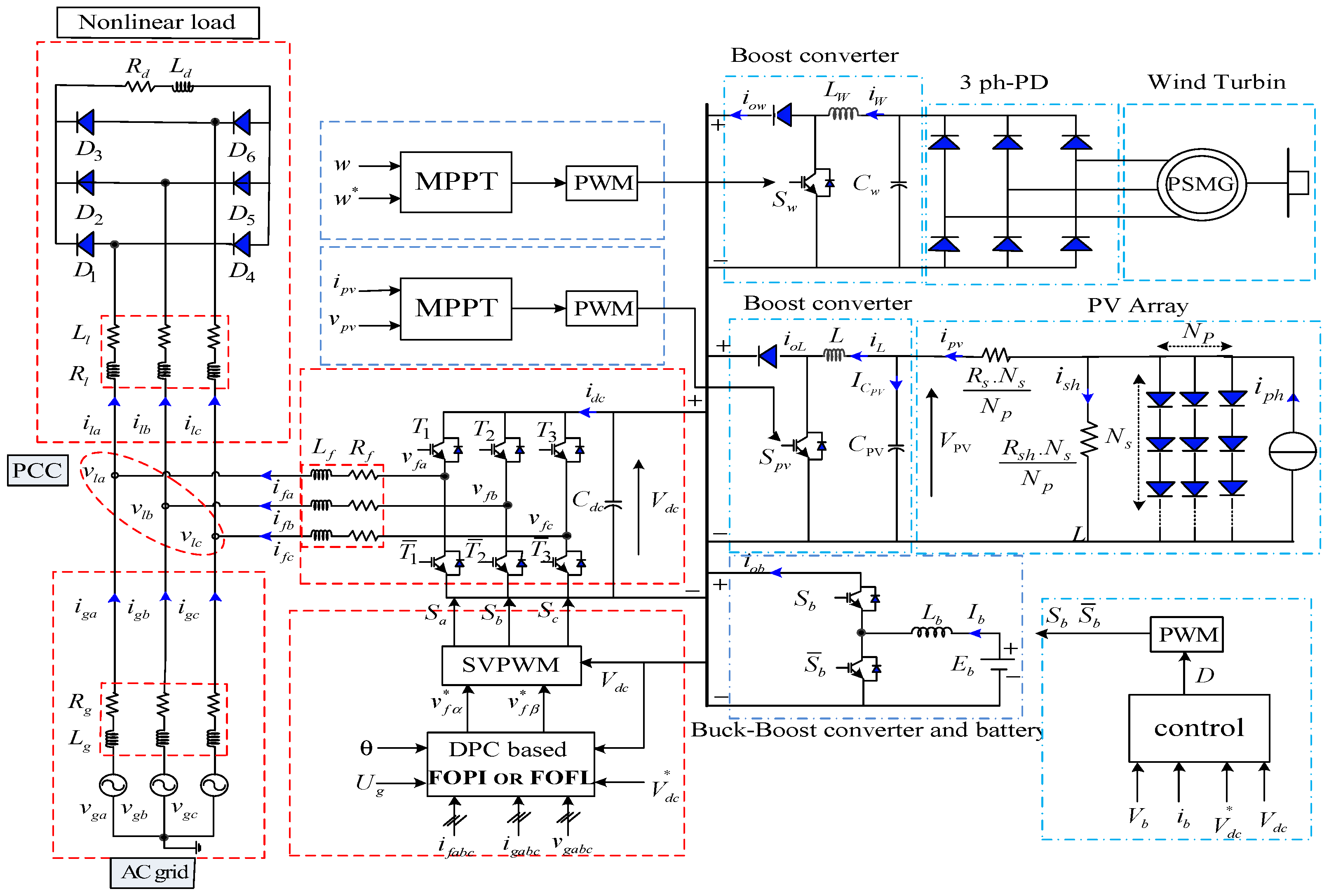
The main findings of this work confirm that the FOFL controller significantly outperforms benchmark methods in both steady-state and transient conditions. In particular, the results show a substantial reduction in THD, faster convergence during dynamic events, and more stable DC-bus voltage regulation under disturbances and parameter changes. These improvements directly translate into enhanced overall system efficiency and reliability. The proposed system, illustrated in Figure 1, is implemented and validated using MATLAB, where extensive simulations verify its effectiveness through both graphical and quantitative performance assessments.
The remainder of this work is structured as follows. In Section 2, the architecture and modeling of the global MG system are presented. In Section 3, the discussion transitions to the applications of FOPI control and FOFL control for the MFVSI command. In Section 4, the discussion and results are presented, and in Section 5, the conclusions from the performed studies are outlined.

2. Design and Modeling of the Proposed System

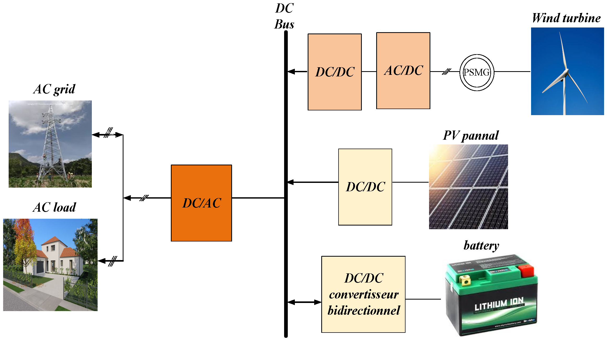
The present study is dedicated to the analysis of the connected MG system. The architectural design of the designed system is illustrated in Figure 2. This architecture signifies the integration of all converter systems (wind, PV, and storage) through a shared DC bus. The utilization of this system is instrumental in safeguarding the environment from the deleterious effects of toxic gases, thereby effectuating a substantial reduction in global warming. Additionally, the system reduces reliance on traditional sources, enabling reduced electricity production and consumption costs. Relying on this energy system has been demonstrated to be a highly effective algorithm for addressing the issue of rising energy demand. For non-petroleum-producing countries, reliance on this well-designed floating system can result in a reduction in energy import expenses, thereby decreasing external dependency.
The proposed wind energy system consists of a WT connected to a PMSG and a three-phase diode rectifier, cascaded with a DC–DC boost converter (DC–DC-BC). The PV system includes a PV array interfaced with a DC–DC-BC, whereas the ESS is composed of a lithium-ion battery integrated with a bidirectional DC–DC chopper. All converter units are linked to a common DC bus, which is interfaced with the point of common coupling (PCC) through a multifunctional voltage source inverter (MFVSI). Together, these subsystems supply a nonlinear load. To enhance PQ at the PCC, FOPI control and FOFL techniques were implemented in the MFVSI control scheme.
To mitigate battery degradation despite frequent transitions between charging and discharging modes, the proposed FOFL-based control strategy is integrated with battery-aware constraints that explicitly account for Depth of Discharge (DoD) and State of Health (SoH). The DoD is regulated by enforcing bounds on the state of charge, thereby preventing deep discharge and overcharge conditions that accelerate wear. In parallel, the SoH is incorporated as an adaptive factor within the control law, allowing the controller to progressively limit battery utilization as aging increases. Moreover, the inherent fractional-order dynamics of the FOFL controller ensure smoother current profiles and reduced transient stress, which helps minimize electrochemical degradation. Additional mechanisms, such as hysteresis bands around switching thresholds, are introduced to avoid rapid and unnecessary charge/discharge cycling. This combined approach enables the system to preserve battery lifetime while maintaining high PQ and stable operation across varying conditions.

2.1. Wind System Model

2.1.1. a-WT Model

A notable technological development that has emerged in recent years is WT, which is undergoing continuous evolution. The utilization of WT facilitates the capture of WE, thereby enabling the generation of electricity, thus rendering it a pivotal component within the energy sector. The classification of these WTs can be categorized into two distinct groups: horizontal-axis WTs and vertical-axis WTs. Additionally, they can be further classified into multi-rotor WTs and single-rotor turbines. The energy output of these turbines is contingent upon WS and turbine dimensions; the larger the WT, the greater the power yield. As indicated in the research conducted in [84], the energy gained from the wind for the turbine can be expressed in the form depicted in Equation (1).
P t = 1 2 ρ A C p ( λ , β ) v ω 3
The area swept by the rotor blades is represented by A, which is equivalent to πR2. The radius of the WT blades is denoted by R. The air density is indicated by ρ. The WT power coefficient is denoted by Cp. The tip speed ratio is denoted by λ. The mechanical angular speed of the WT rotor is denoted by ωm. The blade pitch angle is denoted by β. The WS is denoted by vw.
According to Equation (1), the power gained from wind is related to the Cp, where this coefficient has a value not exceeding 1. In this study, the value of Cp was obtained by utilizing Equation (2).
C p ( λ , β ) = c 1 c 1 λ i c 1 β c 4 e c 5 λ i + c 6 λ λ i = 1 λ + 0.08 β 0.035 β 3 + 1 1
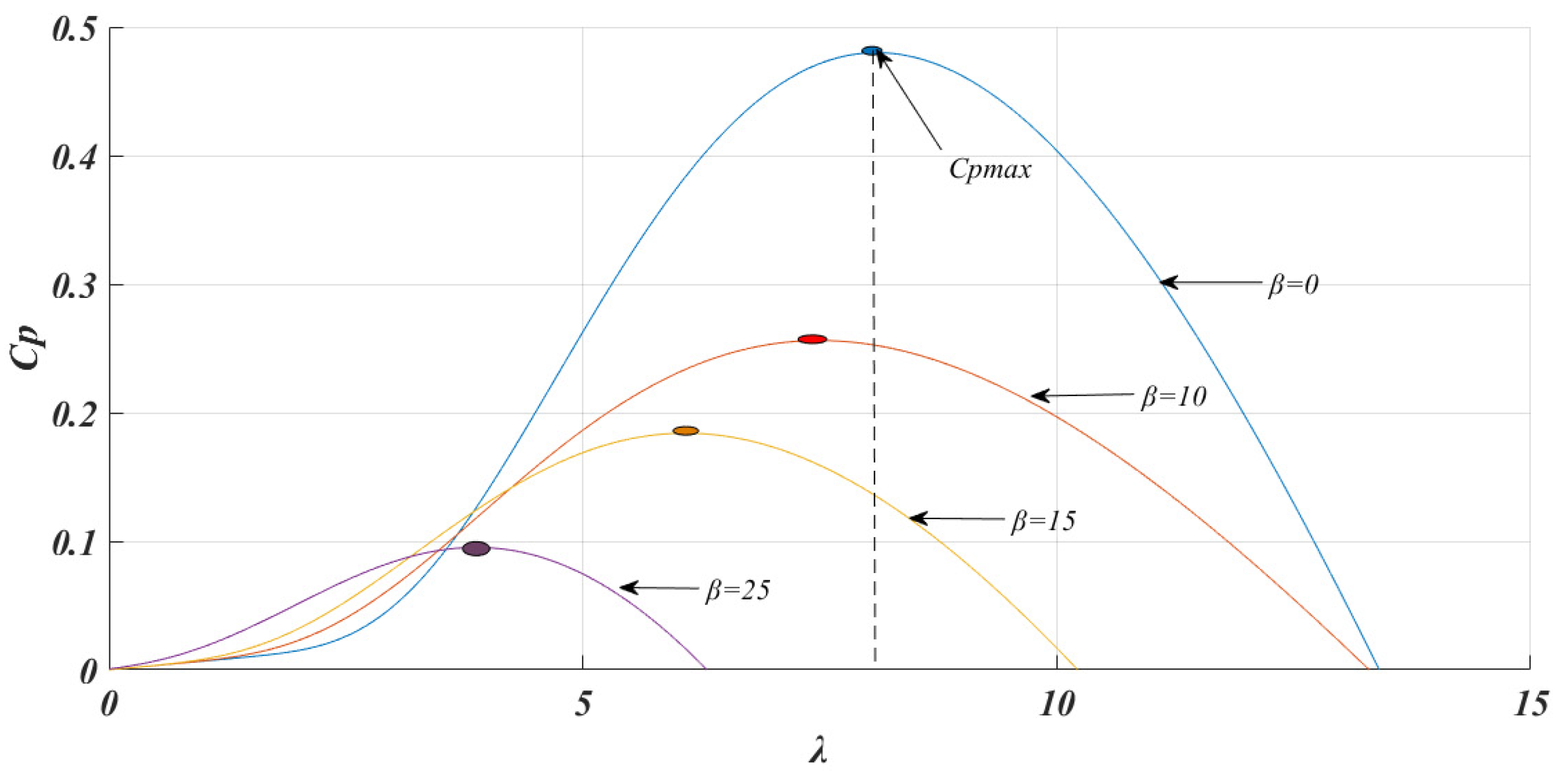
In this equation, “λ” denotes the tip speed ratio, and “c1 to c6” represent the coefficients that are contingent upon the WT design parameters. The coefficients are provided by the manufacturer. The characteristic is illustrated in Figure 3. As illustrated in Figure 3, it is evident that when the angle reaches a specific value, Cp attains its maximum level, which corresponds to the optimal angle. Conversely, the maximum value of Cp was observed to be 0.48 when β = 0°.

2.1.2. b-PMSG Model

The PMSG is a reliable type of generator employed in power generation. The device exhibits high efficiency, excellent performance, and ease of control. However, it should be noted that the cost of the latter is generally higher than that of an induction generator. The generator is connected to the grid from the stator using two inverters [85]. To model the PMSG, a Park transformer is utilized, thereby providing equations that represent the electrical and mechanical components of the machine. As indicated in the research conducted in [86], the mathematical model of the generator can be expressed by Equation (3).
v s d = R s . i s d + L d d i s d d t p . ω m . L q . i s d v s q = R s . i s q + L q d i s q d t p . ω m . ( L q . i s d + Φ P M ) ω e = n p . ω m , T e = 1.5 n p ( L d L q i s d + Φ P M i s q )
In the context of the electrical machine, the following variables are of significance: Rs denotes the stator resistance, while vsd, vsq, isd, and isq represent the dq components of the voltage and current vectors. The direct and quadrature stator inductances are denoted Ld and Lq, respectively. The flux created by the permanent magnets is represented by Φ P M . The electrical and mechanical angular speed of the PMSG rotor is indicated by ωe and ωm, respectively. Finally, np signifies the PMSG pole pair’s number.

2.2. PV System Model

2.2.1. a-PV Panel Model

In the domain of RE, the PV system is regarded as one of the most effective and reliable solutions for the provision of electrical energy. This system is distinguished by its ease of control, simplicity, cost-effectiveness, and ease of realization, which render it a solution of significant importance [87]. The mathematical modeling of the PV system has been the subject of research in several studies [88,89]. According to the findings reported in [90], the expression for the output current of the PV system can be expressed using Equation (4).
i p v = N p i p h N p i 0 exp q N s . k . γ . T v p v + N s N p R s i p v 1 N p v p v + N s N p R s N s N p R s h i p v
With:
i p h = G G r e f i p h , r e f + μ i s c ( T T r e f )
i 0 = i 0 , r e f T T r e f 3 exp q E G k γ 1 T r e f 1 T
In this study, Iph denotes the photocurrent, while Io represents the diode reverse saturation current. The number of PV panels connected in series and parallel is indicated by Ns and Np, respectively. The parameter γ refers to the quality factor, q is the electron charge (1.602 × 10⁻¹⁹ C), and K is the Boltzmann constant (3.807 × 10 − 23 J/K). The terms Rs(Ω) and Rsh(Ω) correspond to the series and shunt resistances, respectively. Moreover, G (W/m2) represents solar irradiance, μ is the short-circuit current temperature coefficient (A/K), T is the operating temperature of the cell, EG denotes the band-gap energy, and “ref” refers to the reference testing conditions.

2.2.2. b-DC-DC-BC Model

In the field of RE, especially in PV systems, the use of a DC-DC-BC is highly significant and regarded as an essential component. This converter enables the integration of the PV system with other system elements and is also used to manage battery charging and discharging processes [91]. DC-DC-BCs offer several advantages, including simple design, low cost, ease of realization, fewer required components, and straightforward control. In most cases, the MPPT is applied to control the operation of the DC-DC-BC. The mathematical expression of the DC-DC-BC is given as follows [92]:
d v p v d t = 1 C p v i p v 1 C p v i L d i L d t = 1 L ( 1 D ) v p v 1 L v d c d v d c d t = 1 C d c i d c
In this context, vpv and ipv denote the output voltage and current of the PV panel, respectively. The inductor current of the DC–DC buck–boost converter is represented by iL, while vdc refers to the DC-link voltage. The duty cycle is indicated by D, and the electrical parameters of the DC–DC converter are represented by Cpv and L.

2.3. Battery Storage System Model

2.3.1. a-Battery-ESS Model

In the domain of RE, ESSs play a pivotal role. The utilization of ESSs has been demonstrated to markedly augment the significance of energy systems. This is because ESSs facilitate the storage of surplus energy, thereby ensuring its availability to supply the grid during critical situations. Lithium batteries are frequently utilized in these applications. Despite the significance of storage systems, their implementation can lead to an escalation in system complexity and expenses. According to the findings reported in [93], the energy stored in the battery can be expressed by the following equation:
E g = E g 0 k Q Q i b . d t + A e B i b . d t
In the context of the given equation, the term “Ego” is equivalent to the battery constant voltage (V), the term “K” is analogous to the polarization voltage (V), the term “Q” is equivalent to the maximum battery capacity (Ah), the term “∫ib.dt” is equivalent to the actual battery charge (Ah), the term “A” is equivalent to the exponential zone amplitude (V), and the term “B” is equivalent to the exponential zone time constant inverse (Ah)−1.
The battery state-of-charge (SOC) must be managed through the utilization of Equation (9) [94].
d ( SOC ) d t = η b Q b i b
where Qb is the battery capacity, and ηb is the battery efficiency.

2.3.2. b-Bidirectional DC-DC-BC Model

The bidirectional DC-DC-BC is a particularly noteworthy variety of DC-DC-BC, and it is indispensable, especially in the field of charging and discharging batteries. The converter is characterized by its simplicity, ease of construction, cost-effectiveness, and accessibility. Equation (10) represents the BESS model.
d i b d t = v b i b R b D v d c v b = E g R b i b
where Vb is the battery output voltage, ib is the battery current, D is the duty cycle of the DC-DC-BC, and Rb is the battery resistance.

2.4. Grid Current Model

2.4.1. a-Grid Model

According to the findings of [95], the network model in the d-q rotating frame employed in this study is represented by Equation (11).
v g d v g q = R g 0 0 R g i g d i g q + L g 0 0 L g d d t i g d i g q + L g 0 ω ω 0 i g d i g q + v l d v l q
It is imperative to note that VGD, VGQ, IGD, and IGQ represent the dq components of the grid current and voltages. Furthermore, Rg and Lg denote the grid source resistance and inductance, respectively. Finally, ω signifies the grid electrical pulsation.
The model can be simplified as follows when the grid voltage component is aligned with the d-axis.
v g q = U g = 2 3 U g m   w i t h   v g d = 0
The amplitude of the phase grid voltage is denoted by Ugm.

2.4.2. b-MFVSI Modeling

As indicated in [96], the final form of the mathematical equations of the SAPF can be estimated using Equation (13).
d i g d d t d i g q d t = R s ω ω R s i g d i g q + 1 L g v g d v g q + 1 L f v f d v f q

3. The Designed Algorithm of the MG Converter

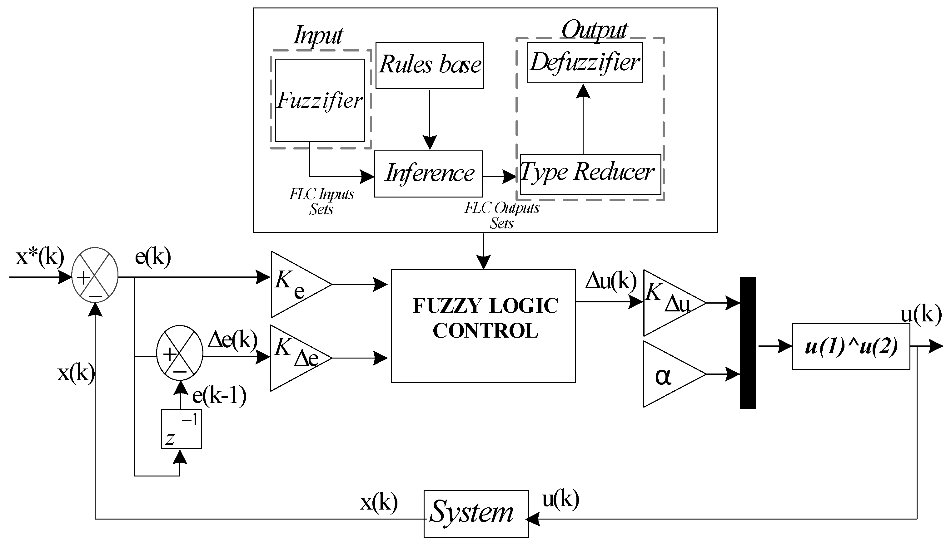
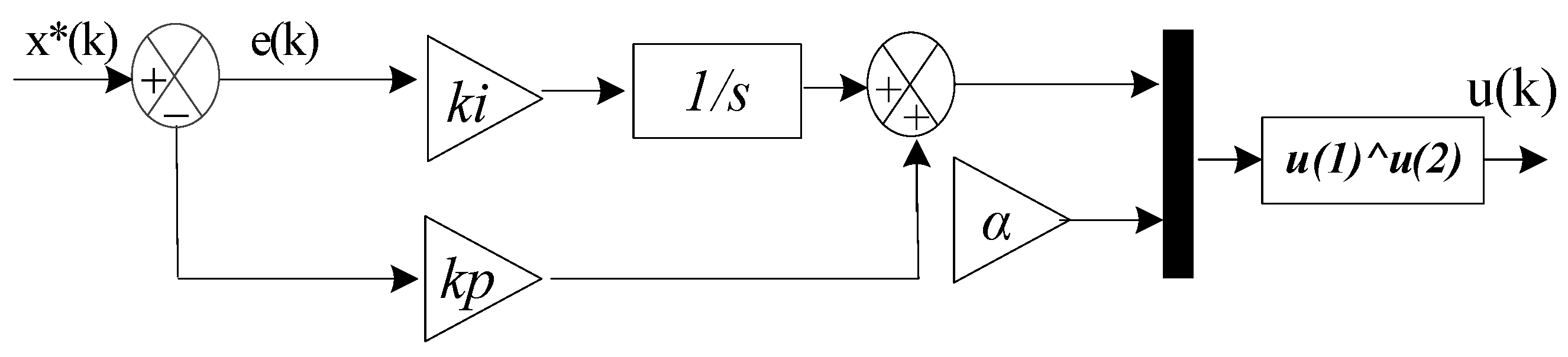
In this section, we will examine the application of the FOPI in comparison with the FOFL technique, which is utilized in the domain of artificial intelligence. The FOFL technique signifies a sophisticated approach for MG management, offering enhanced flexibility, precision, and robustness. This renders it a promising choice for optimizing the use of RE while ensuring stability and quality of energy supply. As illustrated in Figure 4, the designed FOPI aims to enhance the efficacy of the DPC. This approach is distinguished by its simplicity, ease of realization, and limited effectiveness. The utilization of this method does not necessitate a comprehensive understanding of the mathematical model underpinning the system under investigation. Conversely, the functional diagram of the FOFL system is depicted in Figure 5.
The error (e) and its variation (Δe) function as inputs, while the change in control law (∆uk) and the gain (α) act as outputs.
u ( k + 1 ) = u k k + K Δ u . Δ u ( k )
E e = K e . e E e = K e . e
where Ke, K e , and Ku are the normalization gains of variation in errors, error derivative, and control law.
The idea of the FOFL technique is very simple and can be expressed with the equation below:
u ( t ) = ( fuzzy ( X * X ) ) α
To obtain the desired fractional order control, it is necessary that α be distinct from zero and one. In the event that α = 1, the controller is designated as an FL controller. The FL controller architecture used in this work is included in the Supplementary File (see Figure S1). Forty-nine rules, as shown in Table S1 (see Supplementary File), were used to implement the FL controller. These rules were employed to achieve a fast DR and satisfactory operational performance. The Membership function architecture used in this work is shown in Figure S2 (Supplementary File).
The fractional-order exponent α in Equation (16) plays a key role in shaping the control action and typically takes values in the range 0 < α ≤ 1. When α = 1, the control law reduces to a conventional (integer-order) form, where the output of the FL controller is applied linearly, resulting in a standard proportional response. In contrast, when α < 1, the control action becomes nonlinear and exhibits a compressive effect, which attenuates large control signals and enhances smoothness, thereby improving robustness against disturbances and noise. As α approaches 0, the control signal tends toward a nearly constant value (for nonzero inputs), significantly reducing sensitivity to input variations but also slowing the system response. From a stability standpoint, this nonlinear mapping can be interpreted within a Lyapunov framework. Consider a candidate Lyapunov function V ( e ) = e 2 2 , where e = XX is the tracking error. The control law u(t) = (fuzzy(e))α introduces a nonlinear gain of the form ∣e∣α−1, which effectively reduces the control effort as the error grows when α < 1. Under standard assumptions on the FL mapping (e.g., boundedness and sector conditions), the time derivative V ˙ ( e ) can be rendered negative semi-definite, ensuring boundedness of system trajectories and convergence of the error. Thus, the parameter α acts as a tuning factor that balances convergence speed and damping, with intermediate values (e.g., 0.5 ≤ α < 1) often providing an effective compromise between fast response and enhanced stability in MG control applications.
  • FOFL controller-based DPC-SVM approach
In this study, the FOFL is designed as a method for regulating the Qs and Ps, filtering harmonics, and minimizing THD to the maximum possible extent. The proposed approach integrates the benefits of both the FL and FO, resulting in a highly efficient approach for enhancing the DRs of the systems. The FOFL controller is utilized to implement conventional DPC techniques, wherein two controllers are employed for this purpose. Moreover, the switching table is substituted by the SVM, thereby distinguishing the designed method from both the usual approach and extant algorithms in the literature. Consequently, the FOFL controller-based DPC-SVM technique signifies an evolution and modification of the classical DPC.
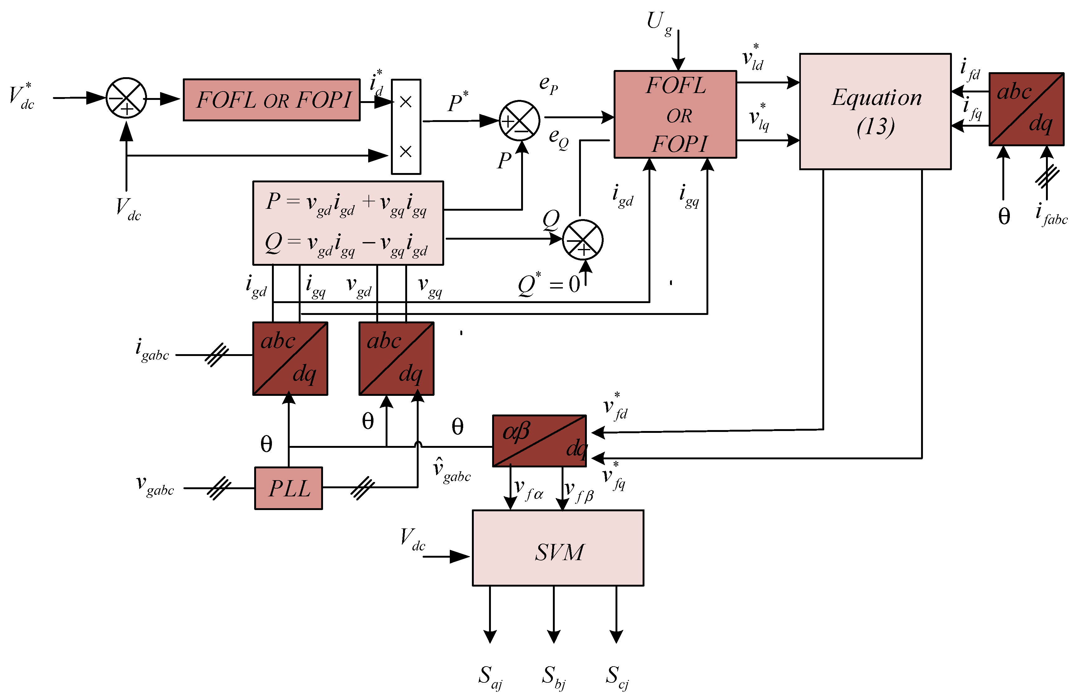
The converter is a three-phase DC–AC converter built on the conventional two-level voltage inverter topology. A modern control strategy based on the DPC-SVM technique is implemented to regulate the converter. The DPC, developed using either the FOPI or FOFL approach, is employed to control the Ps and Qs exchanged with the grid, reduce harmonic distortion, and improve the power factor.
The FOFL strategy consists of two separate control loops. The first loop, known as the DC-link voltage control loop, generates the optimal reference voltage for the DC bus and estimates the maximum current. This estimated maximum current is then used to determine the Psref. The second loop, called the Ps and Qs control loop, generates the reference voltages for the DC bus. In this loop, the reference Qs is fixed at zero, leading to the following condition: Qsref = 0.
The designed approach utilizes a PLL to estimate power, thereby enhancing stability and performance. Additionally, the designed algorithm utilizes an FOFL to regulate the DC link voltage. The utilization of FOFL has been demonstrated to effectively mitigate voltage fluctuations and markedly reduce response time when contrasted with conventional methodologies, such as PI control.
The MFVSI adopts a three-leg inverter topology, enabling the generation of a balanced sinusoidal current with a unity power factor. As a result, zero-sequence switching harmonics are eliminated from the MFVSI output current, which significantly reduces the filtering requirements. As shown in Figure 6, the proposed DPC-SVM technique based on the FOFL controller is implemented using a dedicated schematic configuration. This control algorithm offers high robustness, simple implementation, and fast DR. The performance of the proposed method was evaluated and compared with the DPC-SVM approach based on the FOPI regulator under different operating conditions.
In terms of computational complexity, the FOFL controller exhibits a higher computational complexity than the FOPI controller due to the inclusion of fractional-order operators and a more elaborate control structure, which increases the number of required arithmetic operations per control cycle. In particular, the implementation of fractional dynamics typically involves approximation techniques (e.g., recursive filtering or series expansion), leading to additional processing overhead compared to the relatively simpler structure of the FOPI controller. As a result, the FOFL approach incurs an estimated increase of about 20–35% in execution time per control cycle. Nevertheless, this increase remains moderate and does not compromise real-time applicability, as both controllers can be implemented on standard embedded platforms. While the FOPI controller is well-suited for low- to mid-range microcontrollers, the FOFL controller may benefit from more capable hardware such as DSPs or microcontrollers with floating-point support to ensure efficient real-time performance.
The membership functions (MFs) and rule base of the FL controller were established through a combination of heuristic knowledge, system behavior analysis, and iterative refinement. Initially, the MFs were defined using simple triangular and trapezoidal shapes based on the physical interpretation of key input variables, ensuring smooth transitions and computational efficiency. The rule base was formulated from expert knowledge of the power flow management objectives, including energy efficiency, system stability, and battery protection, with each rule corresponding to a specific operating condition. To ensure that the controller remains effective and near-optimal across the six operating states (States 1–6), a systematic validation process was conducted. This included state-by-state analysis, extensive simulations under varying operating scenarios, and iterative tuning of both MFs and rules based on performance metrics such as power balance, response smoothness, and robustness to disturbances. Additionally, sensitivity analysis was performed to evaluate the controller’s resilience to uncertainties, while careful design of MF overlaps and rule consistency ensured smooth transitions between states. This methodology enables the FL method to maintain reliable and adaptive performance across all defined operating conditions.
Recent studies have explored fractional-order and intelligent control techniques for improving PQ in active filtering and HPSs. For instance, D. Krishna et al. [97] and Habib Benbouhenni et al. [98] demonstrated the effectiveness of FOFL controllers in UPQC and WE applications, respectively, highlighting their advantages in handling nonlinearities and uncertainties. Similarly, conventional SAPF control strategies based on instantaneous Qs theory, such as those reported by D. M. Soomro et al. [99], and DPC-SVM-based approaches developed by Sabir Ouchen et al. [100], S. Saidi et al. [101], and Naamane Debdouche et al. [102], have shown strong performance in harmonic mitigation and dynamic control but largely rely on classical, robust, or integer-order control structures. Despite these advances, the integration of the FOFL technique within a DPC method with an SVM (DPC-SVM) framework for SAPF applications remains insufficiently addressed in the literature. To bridge this gap, the present work proposes a unified FOFL-DPC-SVM control strategy in which a specifically designed FL inference system is coupled with fractional-order dynamics to enhance adaptability, robustness, and transient performance. The proposed approach not only reduces THD and improves DC-link voltage regulation but also achieves faster DR and greater robustness to parameter variations compared to existing methods, thereby providing a meaningful advancement over current state-of-the-art SAPF control techniques.
The proposed work on fractional-order adaptive FL–based DPC of SAPF distinguishes itself from existing studies by combining three key elements—fractional-order dynamics, FL adaptation, and DPC-SVM—within a unified control framework for HRPSs. In contrast, the study by work [97] focuses on FOFL and FOPI controllers applied to a UPQC configuration, demonstrating improved PQ but without embedding the controller into a DPC-SVM structure or addressing multi-source hybrid systems. Similarly, work [98] employs FOFL for wind energy conversion; however, their approach is limited to generator-side power management and does not consider SAPF-based harmonic compensation or MG-level coordination. On the other hand, classical SAPF control approaches such as those by work [99] rely on instantaneous Qs theory, which is effective for harmonic mitigation but lacks adaptability and robustness under parameter variations. Advanced DPC-SVM strategies proposed by refs. [100,101,102] improve DR and switching performance using robust or vector-based techniques, yet they are predominantly based on integer-order or linear control schemes without intelligent or fractional-order adaptation.
In comparison, the present work introduces an adaptive FOFL controller embedded within the DPC-SVM framework, specifically designed for SAPF operation in multi-converter HPSs. This integration enables simultaneous enhancement of harmonic compensation, DC-link voltage regulation, and system robustness. The main findings indicate that, unlike the aforementioned methods, the proposed approach achieves lower THD, faster settling time, improved transient response, and greater robustness to system uncertainties and renewable intermittency. Therefore, the contribution of this work lies not only in the use of FOFL but in its task-oriented integration with DPC-SVM for SAPF in hybrid MG environments, which provides a more comprehensive and effective solution compared to existing literature.

4. Results

In this section, the proposed MG systems are simulated using MATLAB 2021a. The parameters employed in the simulation are listed in Table 2. To evaluate and demonstrate the system’s optimal performance, several simulation studies were carried out under varying operating conditions, including different WSs, PV irradiation levels, and load demands. Furthermore, a comparative analysis between the two regulators, FOFL and FOPI, is performed to assess their impact on improving system performance and characteristics.
The gains used, and their numerical values, are listed in Table 3. The coefficient α plays a pivotal role in the designed control framework, as it defines the fractional order of the controller and governs the system’s memory effect, thereby directly influencing dynamic performance and robustness. Variations in α modify the balance between responsiveness and damping: higher values tend to accelerate the system response but may reduce stability margins and increase oscillatory behavior, whereas lower values enhance stability and smoothness at the cost of slower convergence. The significantly different values obtained for the two control strategies—α = 3.51 for the FOPI controller and α = 1.28 for the FOFL controller—reflect their distinct operational requirements and control structures. In the FOPI case, a higher α was necessary to achieve rapid error correction and improved transient performance under varying conditions. Conversely, the FOFL controller required a lower α to ensure stable operation and mitigate excessive control effort and sensitivity to disturbances. These values were selected through a systematic tuning and validation process, ensuring that each controller operates near optimally within its intended application domain.

4.1. Test 1

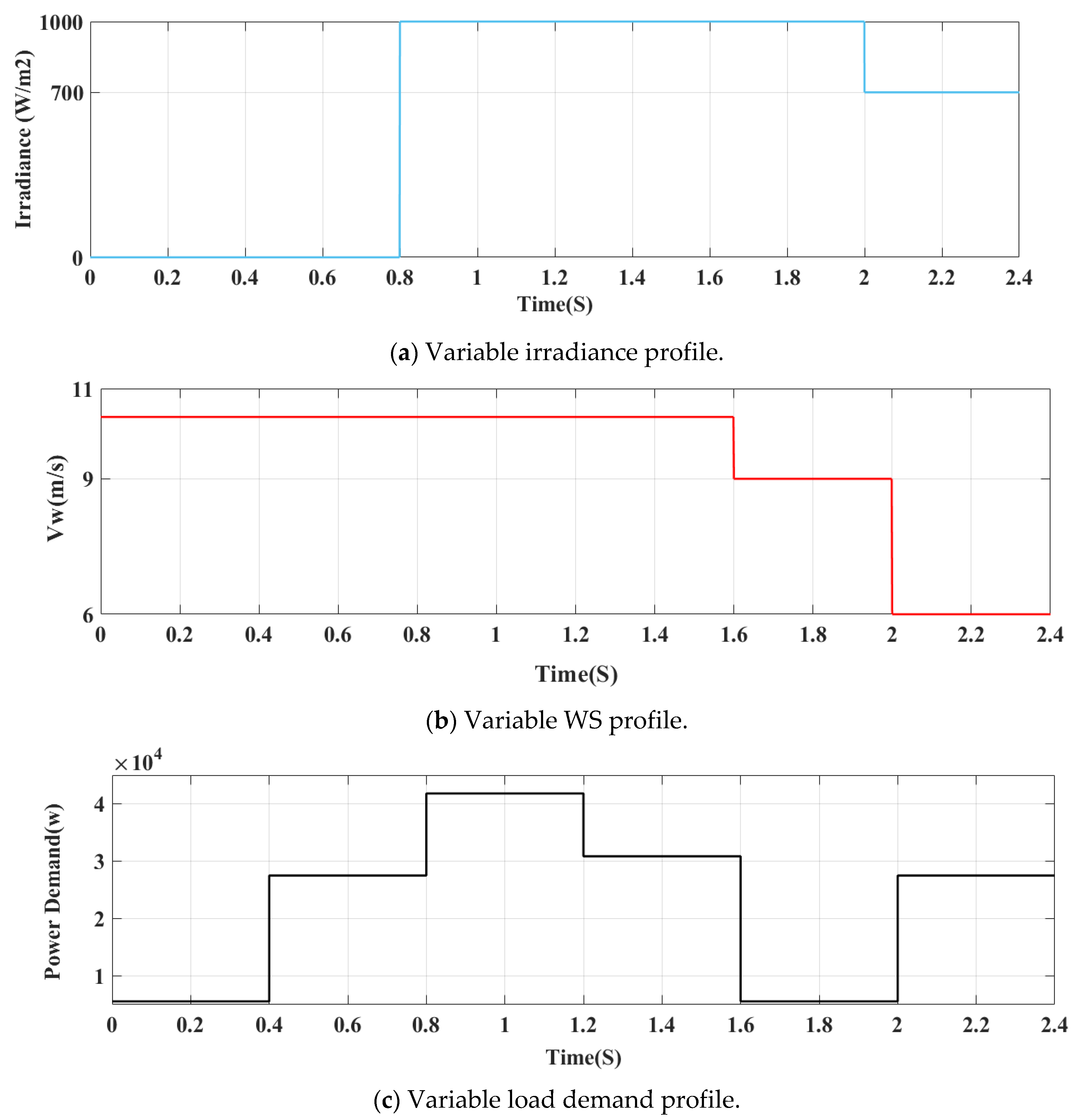
In this experiment, the behavior of the strategies outlined in this paper is examined through the lens of the profiles depicted in Figure 7. As illustrated in Figure 7, the profiles employed in this study for WS, irradiance, and load demand are depicted. The graphical outcomes of this evaluation are delineated in Figure 8, Figure 9, Figure 10 and Figure 11. The numerical values of this test are also listed in Table 4 and Table 5.
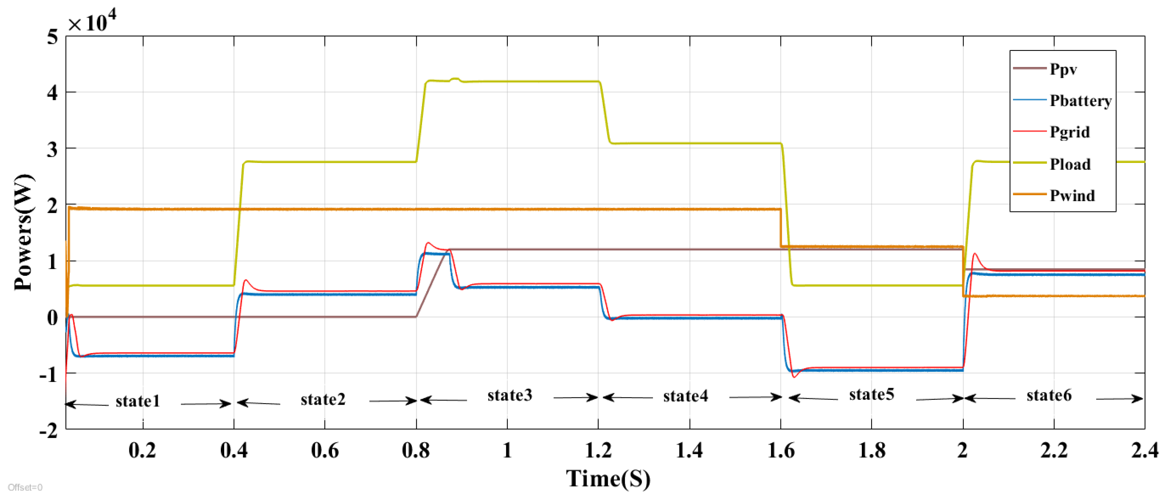
Figure 8 introduces the energy flow management in the MG system.
To accomplish the simulation objectives, the operating period of the MG system was divided into six distinct states, namely States 1 through 6. For each state, different load power demands, WS conditions, and solar irradiation levels were considered.
In State 1 (t = 0 to 0.4 s), the PV system remains inactive due to nighttime conditions. As a result, the irradiance level is very low, the battery storage system is fully charged, and the load demand is low. Under these conditions, the energy generated by the WT is supplied to the grid, while the battery operates in charging mode.
In State 2 (t = 0.4 to 0.8 s), the PV system continues to remain inactive, whereas the WS stays at its maximum value. Since the load demand exceeds the power generated by the WT, the utility grid and the battery jointly supply the required load power.
In State 3 (t = 0.8 to 1.2 s), the irradiance level becomes significantly high, while the WS remains at its maximum value. However, the load demand is still greater than the combined power generated by the WT and PV systems. Therefore, both the grid and the battery contribute to satisfying the load requirements.
In State 4 (t = 1.2 to 1.6 s), both the irradiance level and the WS remain constant at their maximum values, and the load demand matches the total power generated by the WT and PV systems. Consequently, neither the utility grid nor the battery is required to participate in supplying the load.
In State 5 (t = 1.6 to 2 s), the irradiance level remains high. Initially, the WS and the load demand are both low. Under these operating conditions, the excess power generated by the WT and PV systems is delivered to the grid, while the battery operates in charging mode.
Finally, in State 6 (t = 2 to 2.4 s), the irradiance level decreases, the power generated by the WT becomes very low, and the load demand exceeds the total power produced by the WT and PV systems. As a result, the utility grid and the battery are responsible for supplying the required load power.
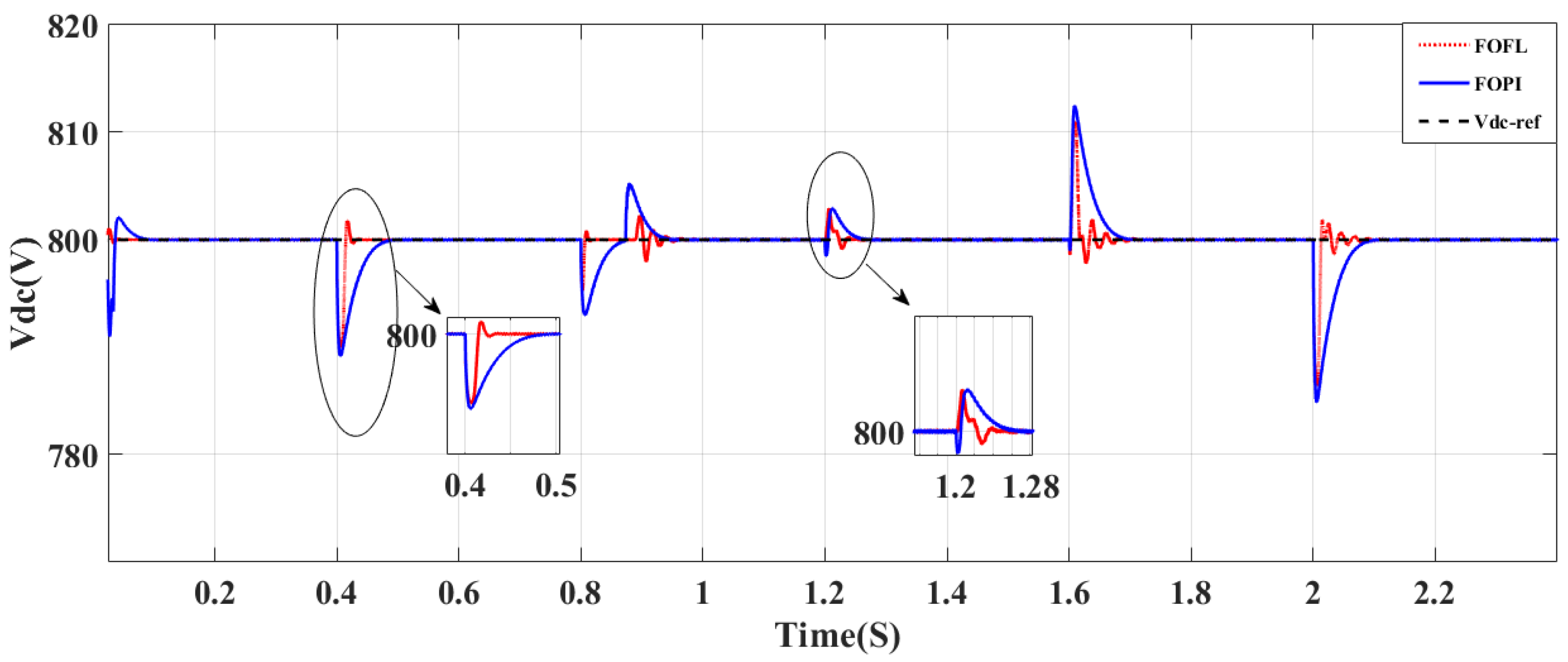
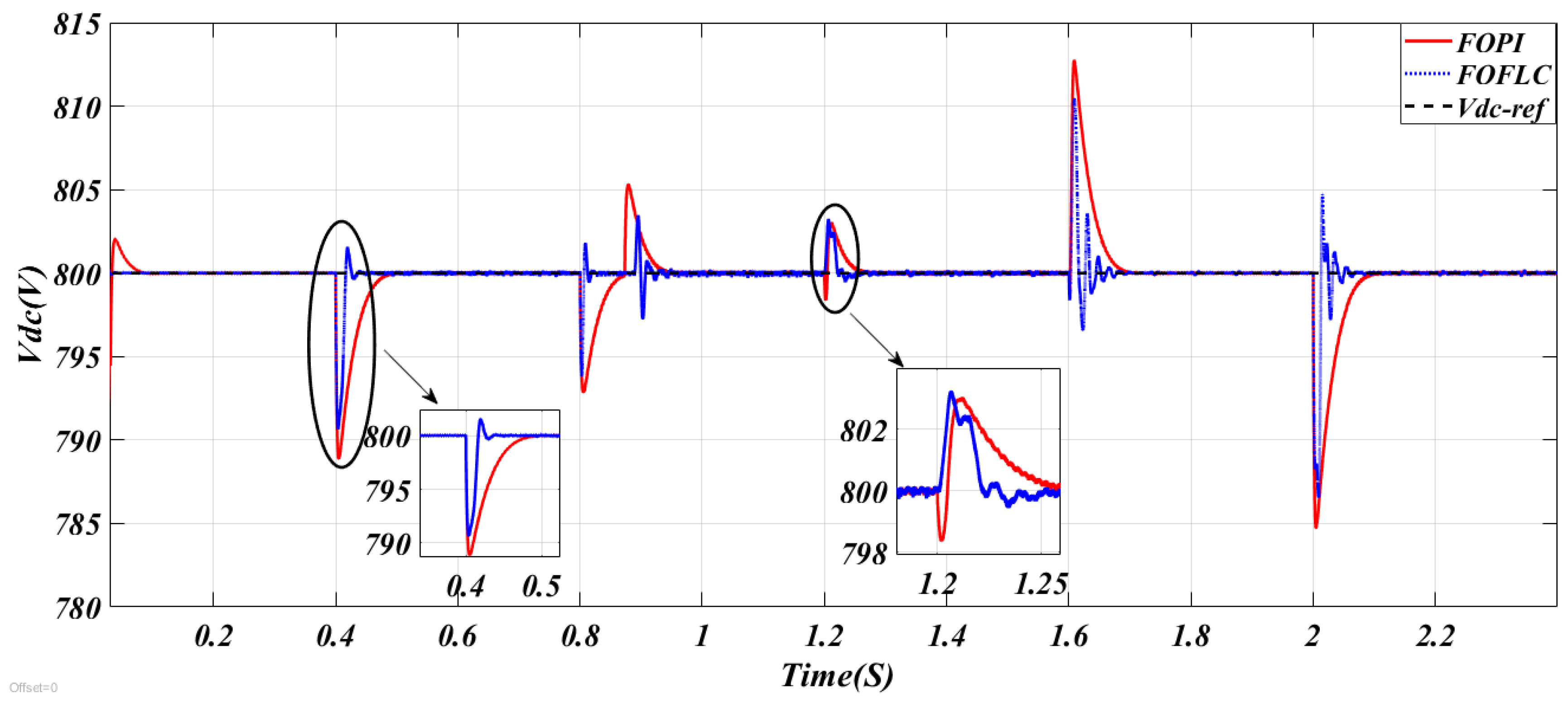
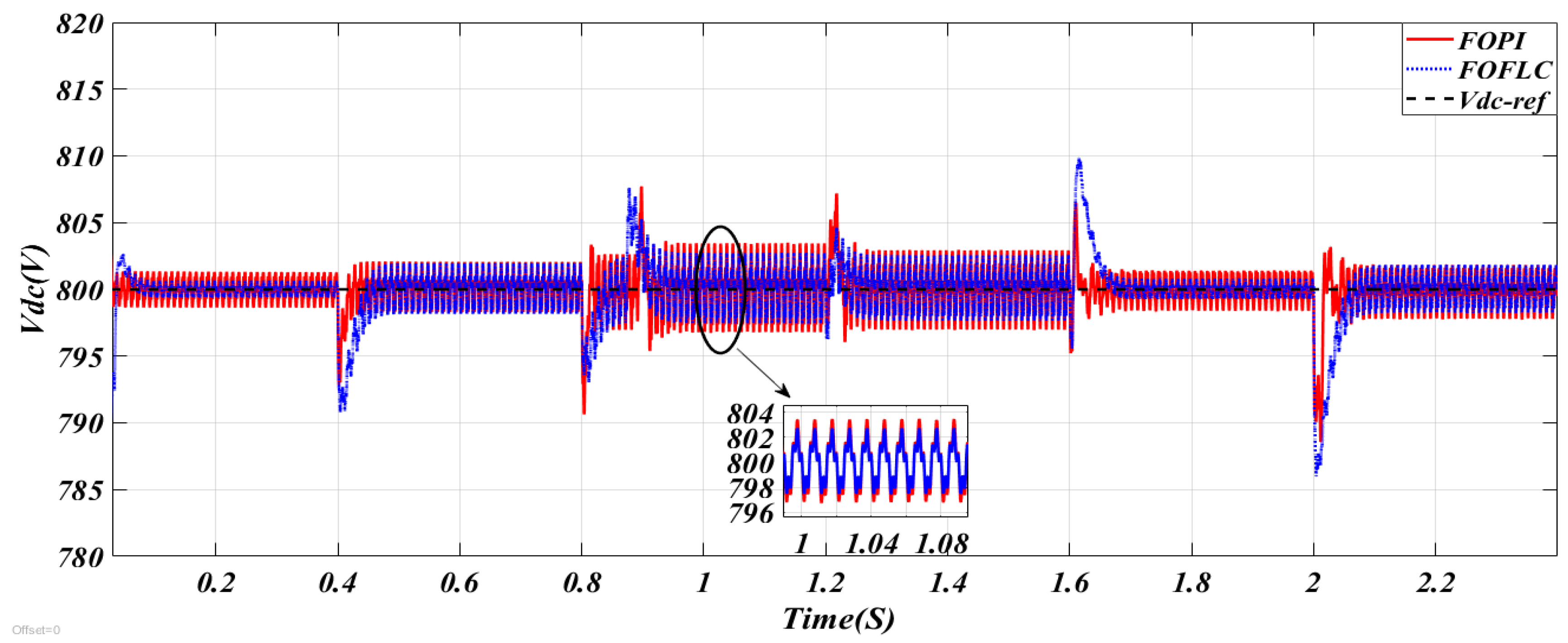
As illustrated in Figure 9, the variation in the DC voltage across two controllers in the initial test case is represented. This figure indicates that the Vdc value closely follows the reference value, remaining constant despite the multiple variations in the WS, radiation, and load patterns. It is also noteworthy that an overshoot of the threshold value is observed when both controls are engaged, with this overshoot being less pronounced when the FOFL is employed in comparison to the FOPI technique. Furthermore, Figure 9 demonstrates that the DC link voltage fluctuations are reduced when employing the FOFL in comparison to the FOPI, thereby substantiating the efficacy, efficiency, and reliability of the FOFL.
Table 4 presents the DC-link voltage dynamic performance for Test 1, comparing the FOPI and FOFL control strategies and highlighting a clear overall advantage of the FOFL approach. The results show that FOFL significantly improves voltage regulation by reducing ripple magnitude from 0.2 V to 0.12 V (40%), overshoot from 0.5% to 0.375% (25%), and steady-state error from 0.1 V to 0.05 V (50%). These improvements can be attributed to the enhanced adaptability of the FL component combined with fractional-order dynamics, which provides smoother control actions and better damping characteristics, thereby reducing oscillations and improving steady-state accuracy. A particularly notable improvement is observed in the response time, which decreases from 0.055 s to 0.015 s (81.81%), indicating a much faster transient response. This behavior reflects the ability of the FOFL approach to react more rapidly to deviations due to its nonlinear decision-making mechanism, which adjusts control effort more effectively than the conventional FOPI structure.
Regarding undershoot performance at different time instants (0.4 s, 0.8 s, and 2 s), the FOFL controller consistently achieves lower values compared to FOPI, with improvements of 10%, 33.33%, and 10.86%, respectively. This indicates improved damping and better recovery behavior during transient disturbances, particularly at intermediate time intervals where the system is most sensitive to dynamic variations. The relatively smaller improvement at 0.4 s and 2 s suggests that both controllers behave similarly during initial and late settling stages, while the most significant advantage of FOFL appears during the mid-transient phase. Overall, Table 4 confirms that the FOFL method provides superior transient and steady-state performance in DC-link voltage regulation, mainly due to its enhanced nonlinear adaptability and fractional-order tuning capability.
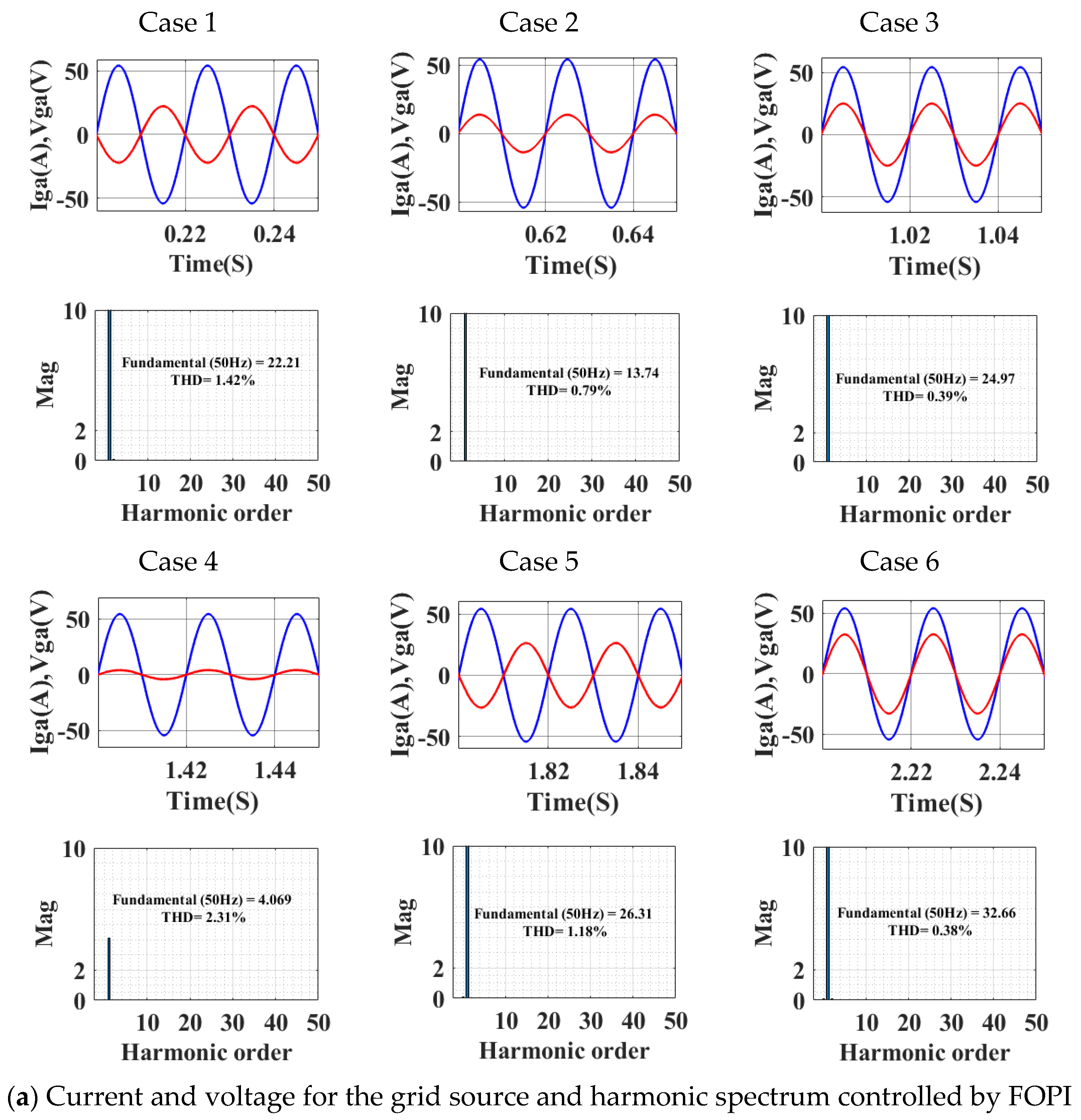
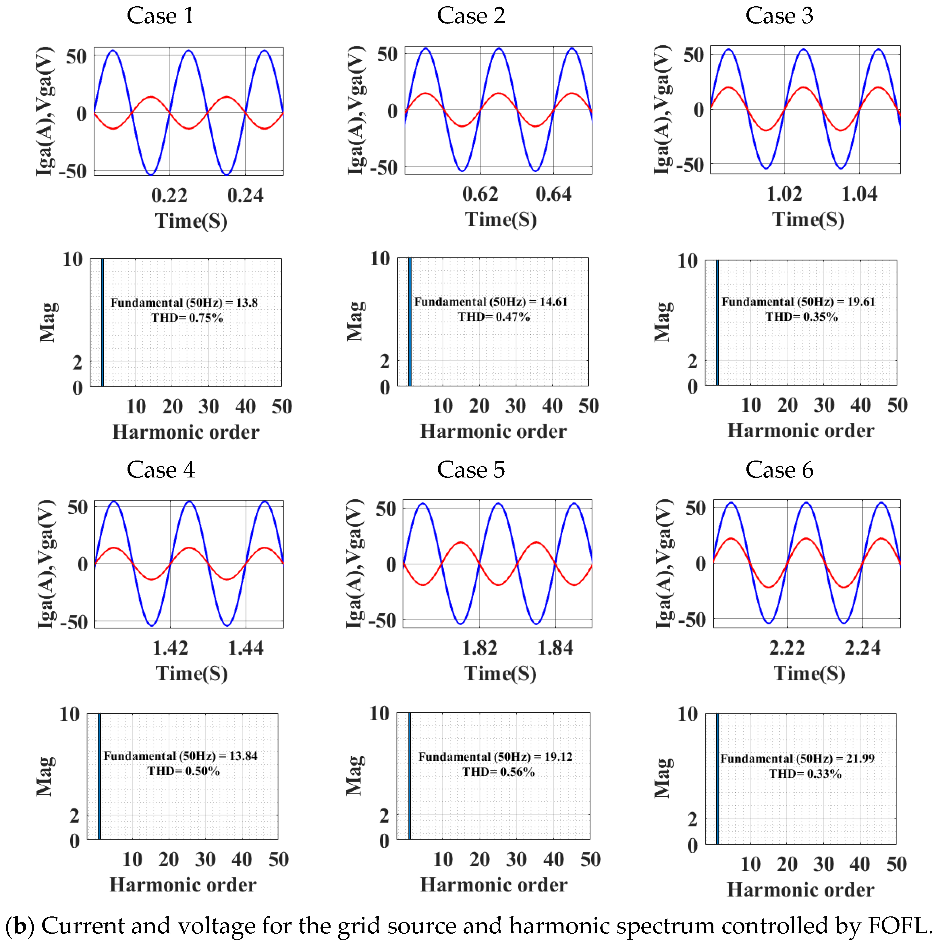
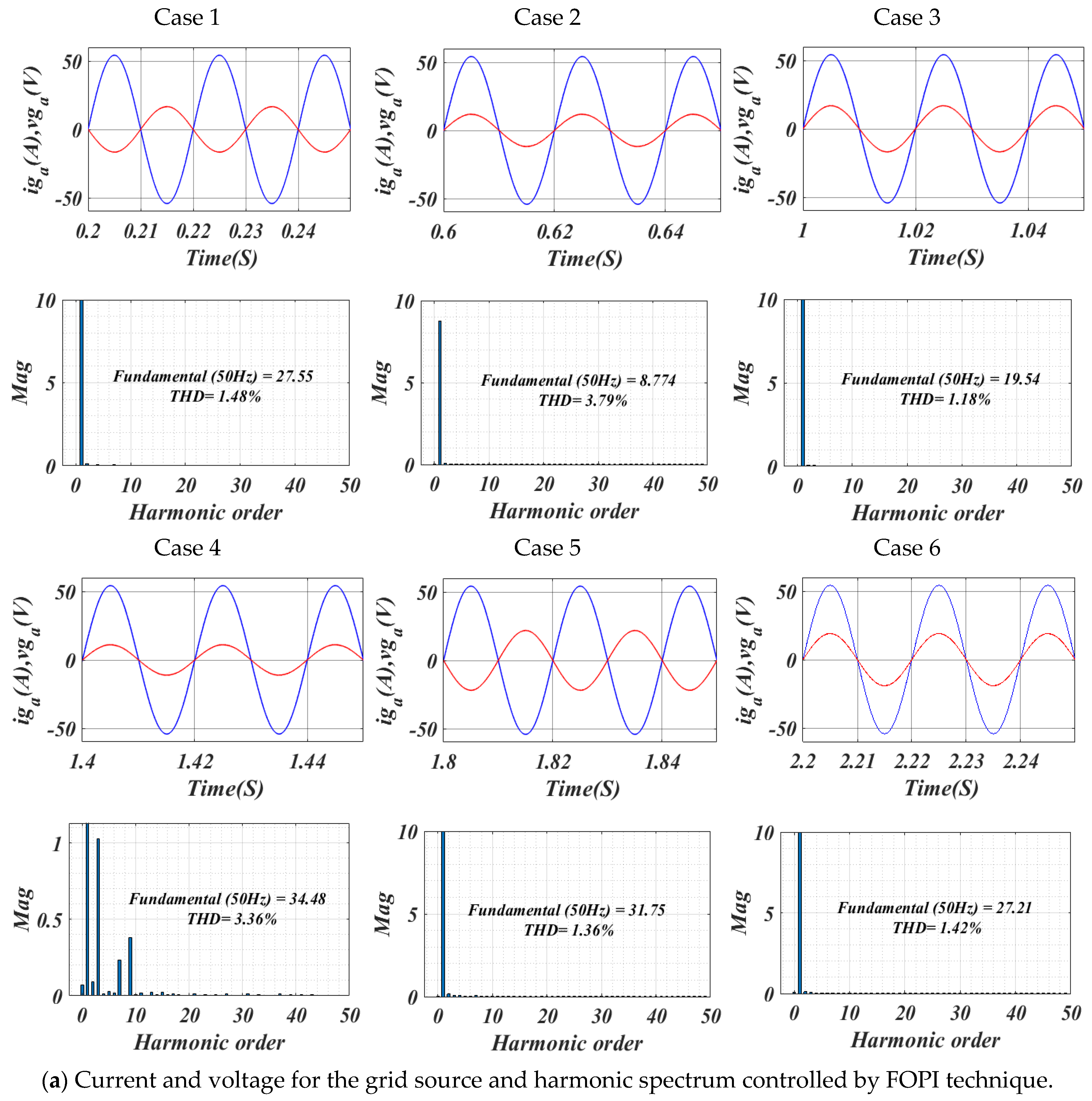
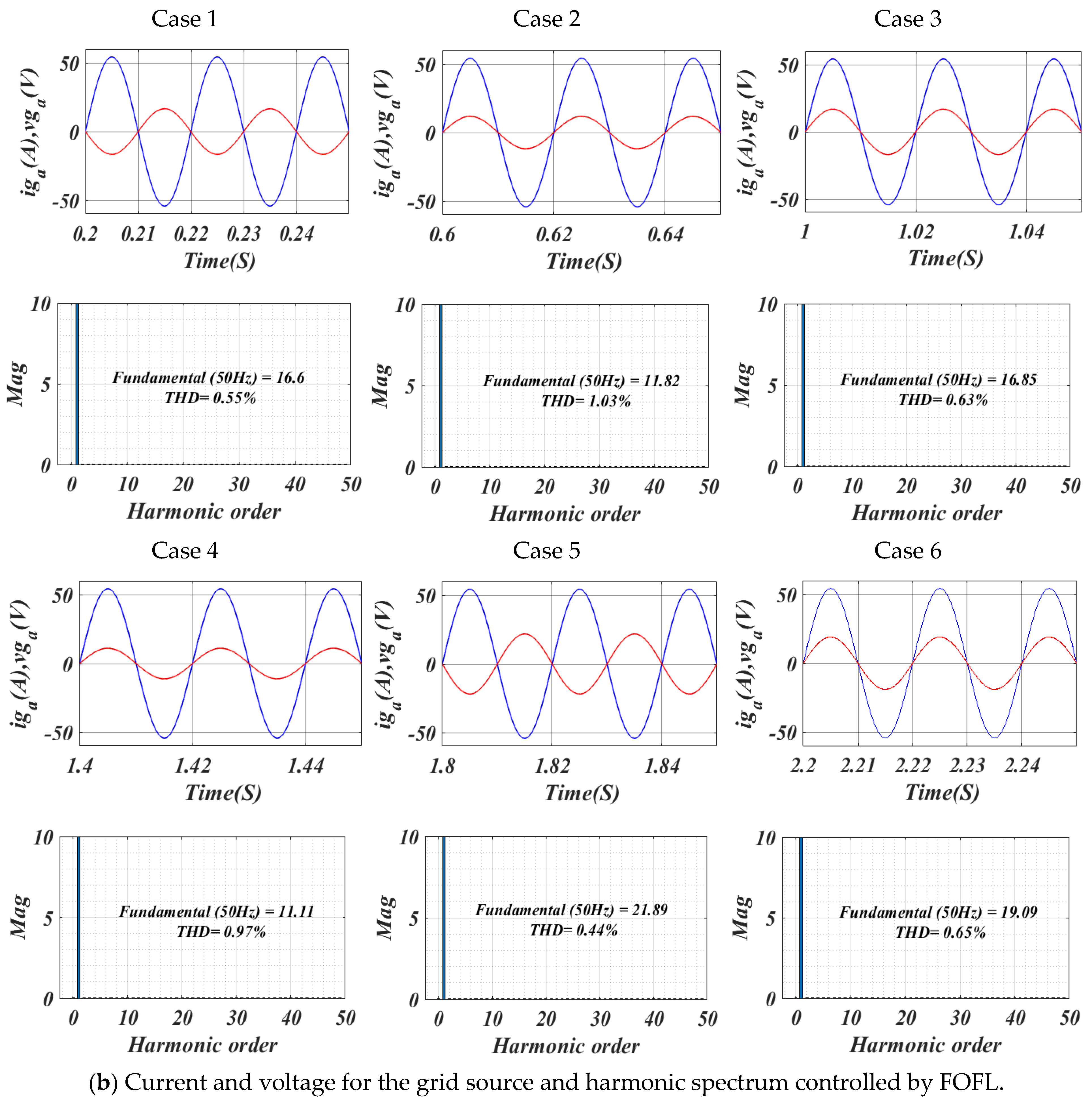
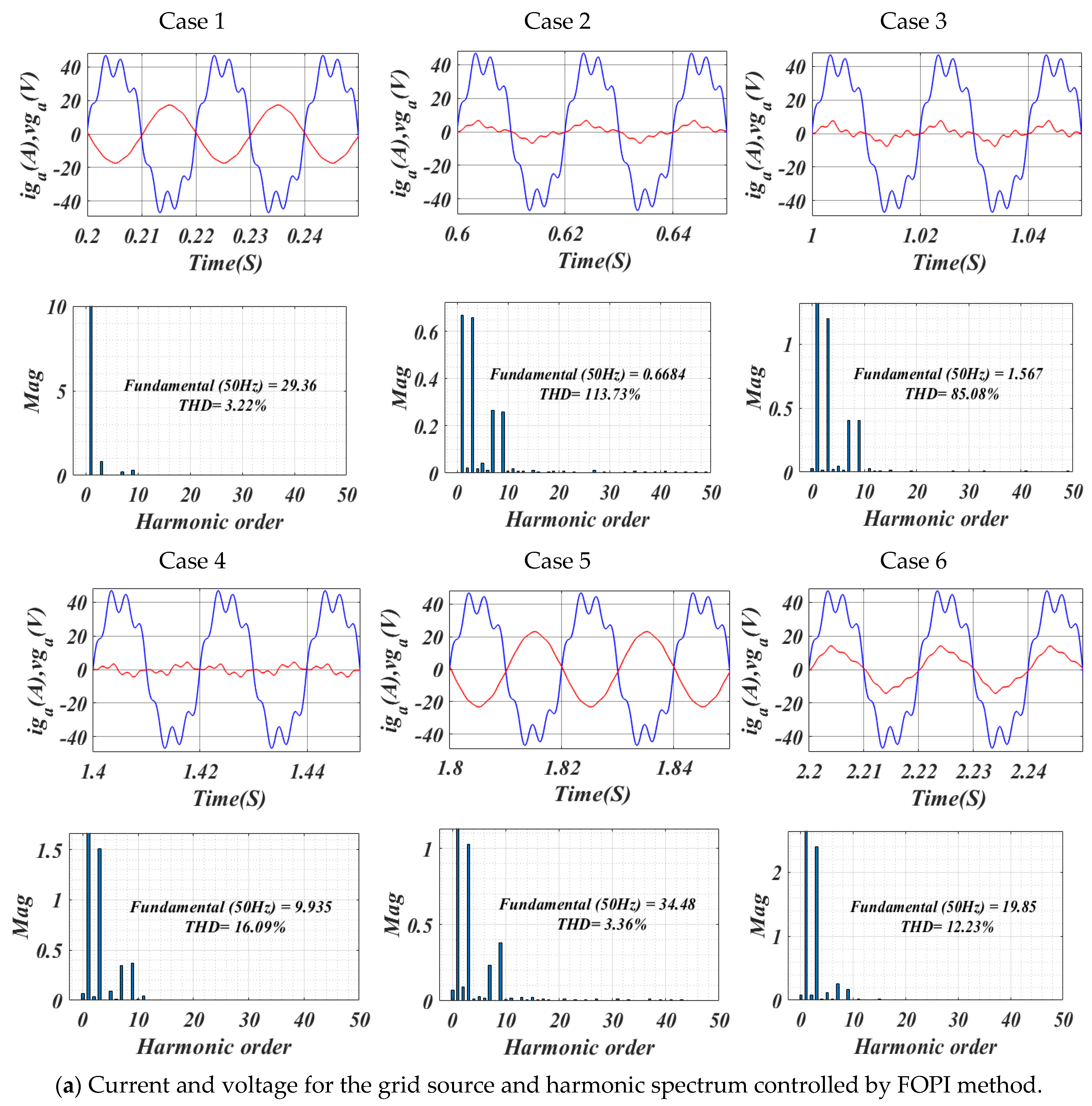
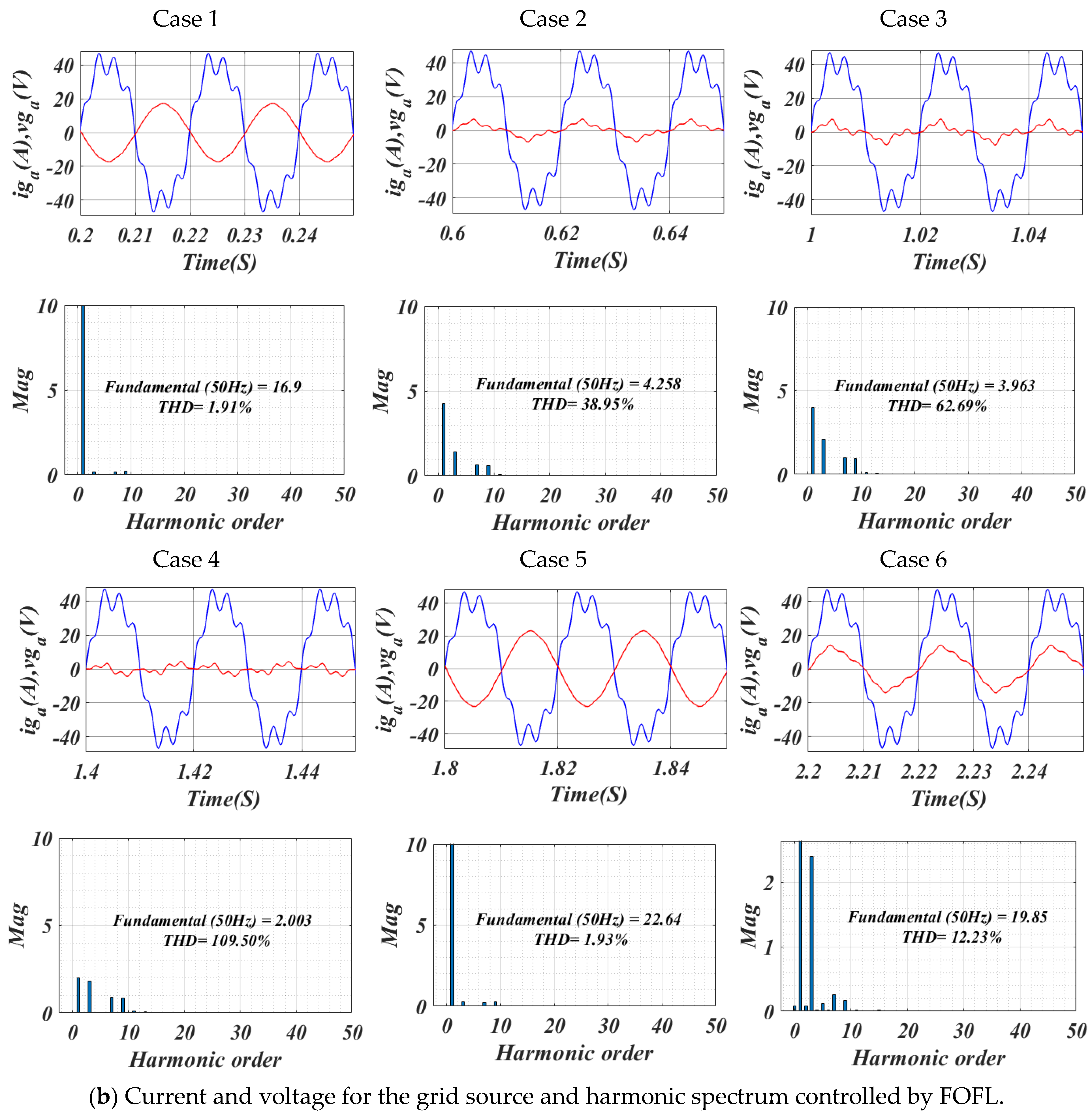
As illustrated in Figure 10, the voltage, current, and THD values for the two controls are contingent upon the load demand, as evidenced by the six cases examined. It is evident from this figure that the voltage and current in all cases exhibit a sinusoidal shape. It is noteworthy that the voltage remains constant in all instances, with a maximum recorded value of approximately 52 volts. However, the current value exhibits variability across different scenarios for the two controls, contingent on the load demand. Consequently, it can be posited that load demand exerts a substantial influence on the current value. It is also observed that the THD value fluctuates between different control states. The THD values for the FOPI and FOFL controls are enumerated in Table 5. Table 5 presents the harmonic performance comparison between the FOFL and FOPI control strategies under Test 1 across six operating cases, highlighting their influence on both THD and the fundamental frequency (50 Hz) amplitude. Overall, the FOFL controller consistently achieves lower THD values than the FOPI approach in all cases, with reductions ranging from approximately 10.26% to 78.35%. This improvement is mainly attributed to the combined effect of FL approach adaptation and fractional-order dynamics, which enhances the system’s ability to suppress switching harmonics and smooth voltage/current waveforms. In particular, Case 4 shows the most significant THD reduction (78.35%), indicating that the FOFL controller is especially effective under highly dynamic or disturbed operating conditions, where nonlinear control action provides superior damping and harmonic mitigation.
Regarding the fundamental frequency amplitude, the FOFL controller shows mixed behavior depending on the operating case. In Cases 1, 3, 5, and 6, the FOFL strategy results in a lower fundamental amplitude compared to FOPI, which suggests a stronger filtering effect that suppresses both harmonic and, to some extent, fundamental components. This reflects the inherent trade-off introduced by aggressive harmonic attenuation, where improved waveform purity may slightly reduce signal magnitude. Conversely, in Case 2, a slight increase in fundamental amplitude is observed (5.95%), indicating more efficient energy transfer and better preservation of the fundamental component under that specific operating condition. Overall, the results in Table 5 confirm that the FOFL controller provides superior harmonic mitigation performance compared to FOPI, while maintaining acceptable control over the fundamental component, with performance variations arising from different operating scenarios and system nonlinearities.
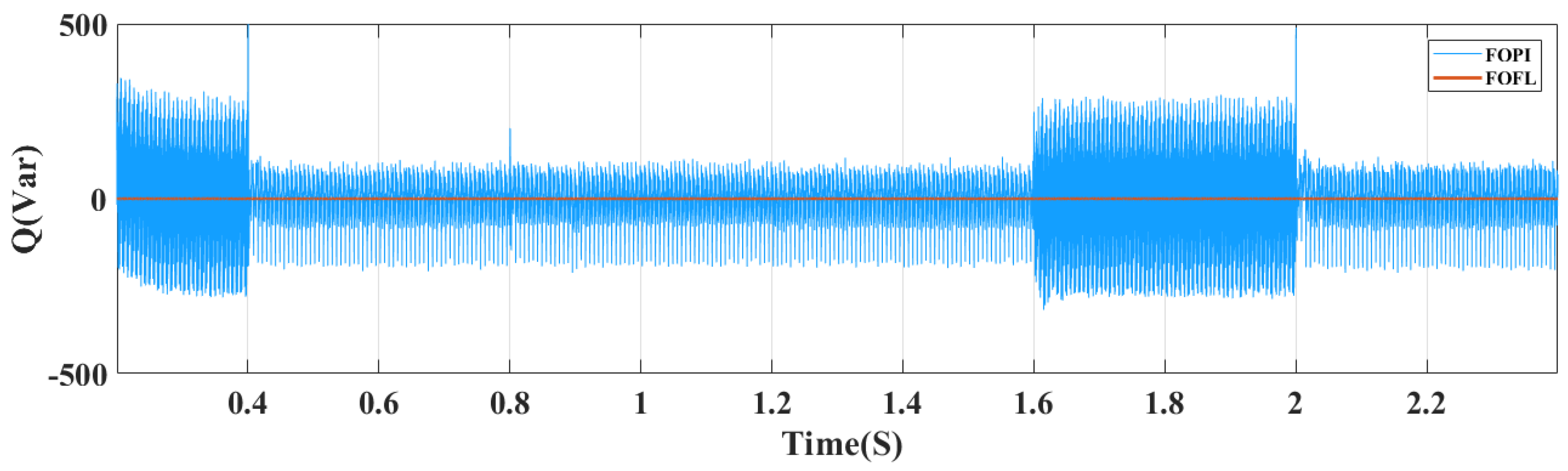
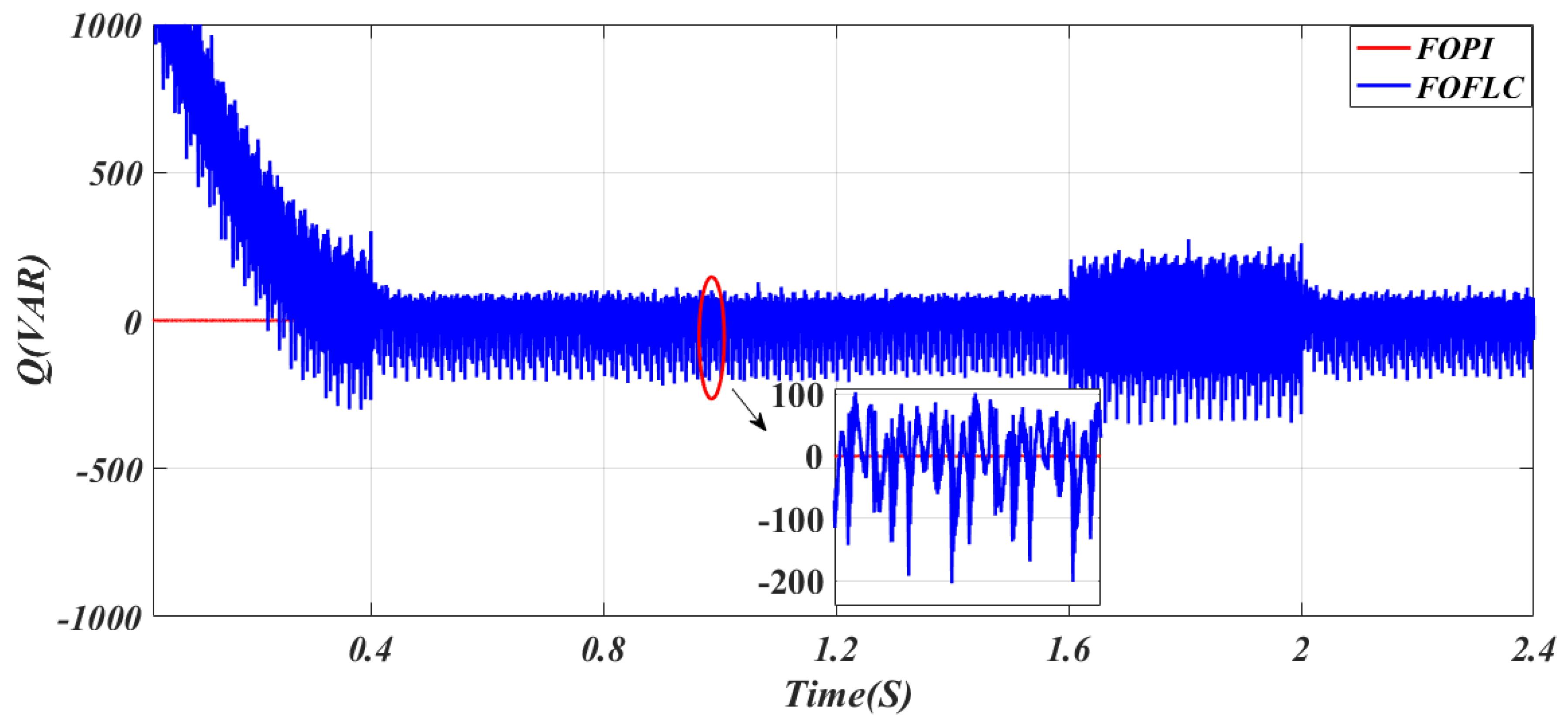
As illustrated in Figure 11, the Qs within the network undergo a temporal variation for the two proposed control techniques. It is evident from this figure that the power value closely follows the reference value for both control strategies and remains constant in the presence of load demand or radiation. Additionally, ripples have been observed at this power level. The FOFL demonstrates a marked reduction in these ripples in comparison to the FOPI approach. The FOFL exhibits negligible Qs, thereby ensuring the compensation is effective in comparison to the FOPI, thereby guaranteeing unit power factor operation.

4.2. Test 2

In this experiment, the effectiveness and efficiency of the designed strategies are studied in terms of varying the system parameters. In this particular test, the resistance values are multiplied by two, while the inductor values are multiplied by 0.5. The results of this test are presented in Figure 12, Figure 13, Figure 14 and Figure 15, and the numerical results are presented in Table 6 and Table 7.
As illustrated in Figure 12, the variation in the DC voltage over time for two controllers is demonstrated. This figure indicates that the voltage remains within the established reference value for both controllers, despite variations in the parameters of the system under investigation. However, a comparison of this figure with Figure 9 reveals a significant impact on the resultant effort, as evidenced by the substantial increase in the overshoot value due to alterations in parameters. This effect was more pronounced when employing the FOPI in comparison to the FOFL approach. The graphical outcomes illustrate the efficacy of the FOFL and its notable resilience to variations in the parameters of the system under investigation.
Table 6 presents the dynamic performance comparison of the DC-link voltage control under Test 2 for both the FOPI and FOFL strategies, showing a clear overall advantage of the FOFL controller. In particular, FOFL significantly improves voltage quality by reducing ripple magnitude from 0.025 V to 0.015 V (40%) and overshoot from 1% to 0.5% (50%), which indicates a more stable and better-damped transient response. These improvements are mainly attributed to the nonlinear adaptive nature of the FL approach component combined with fractional-order dynamics, which enhances disturbance rejection and smooths abrupt control actions. Furthermore, the FOFL technique achieves a substantially faster response time (0.032 s compared to 0.06 s for FOPI), corresponding to a 46.67% improvement, demonstrating its superior ability to quickly track reference changes while maintaining stability. The SSE is also reduced by 26.83%, confirming improved accuracy in voltage regulation.
Regarding undershoot behavior at different time instants (0.4 s, 0.8 s, and 2 s), the FOFL controller consistently outperforms the FOPI strategy with improvements of 18.48%, 14.29%, and 15.98%, respectively. This indicates that the FOFL approach provides better damping and faster recovery during transient disturbances across the entire response period. The observed improvements stem from the fractional-order tuning, which introduces additional flexibility in shaping system dynamics, and the FL inference mechanism, which adapts the control action based on real-time error evolution. Overall, Table 6 clearly demonstrates that the FOFL technique enhances both transient and steady-state performance of the DC-link voltage, making it more suitable for robust microgrid applications.
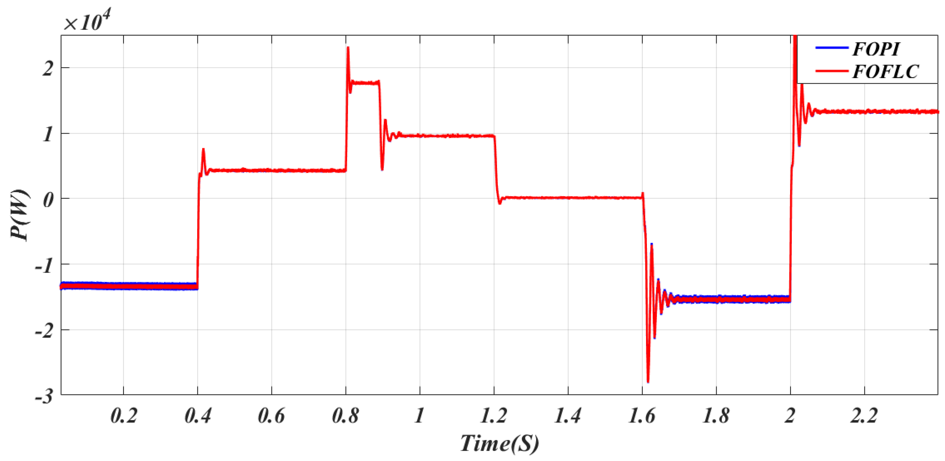
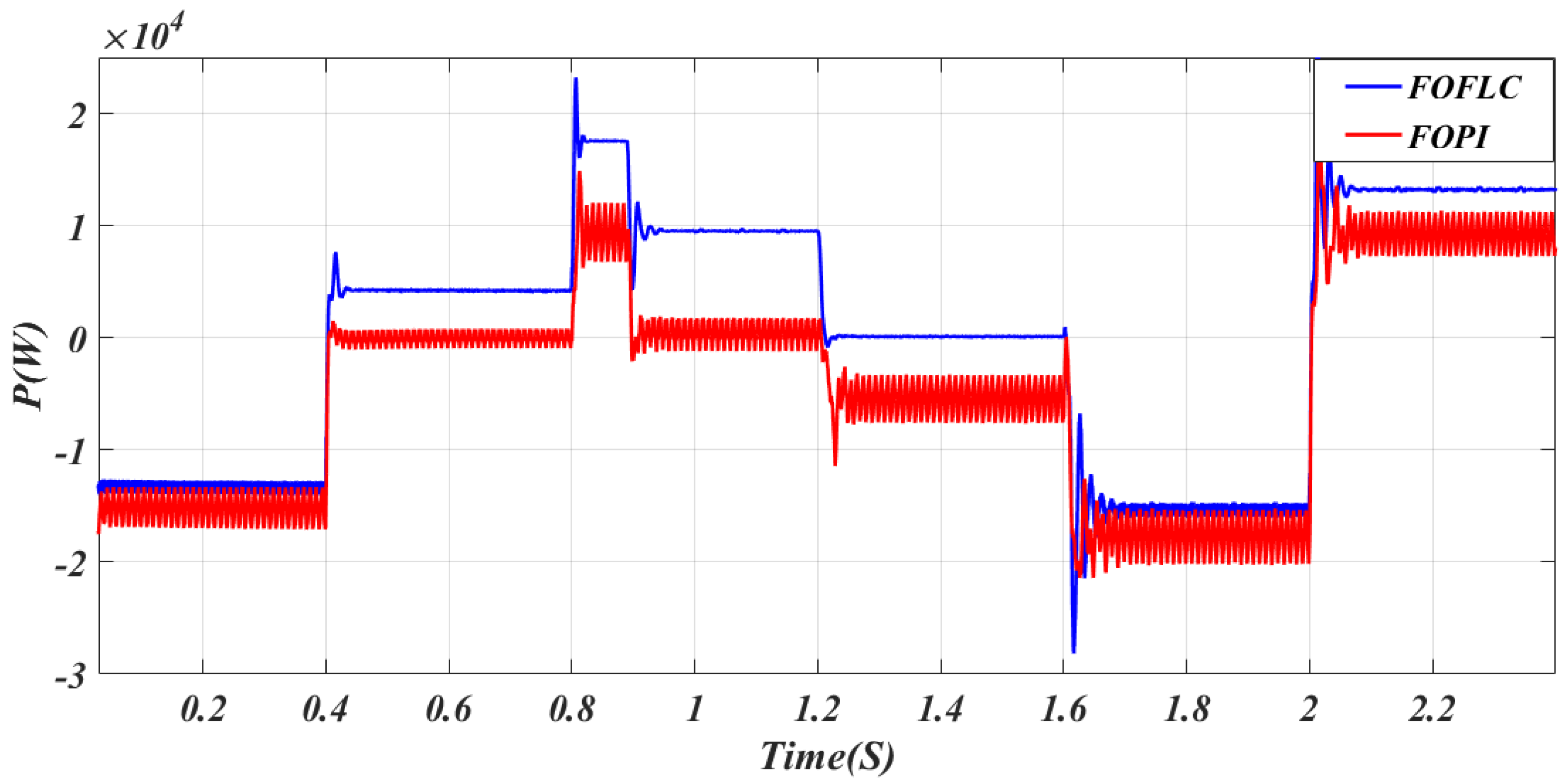
As illustrated in Figure 13, the variation in Ps over time for the two proposed controllers is evident. Notwithstanding the alteration of system parameters, Ps continues to fluctuate in accordance with the load demand, exhibiting peaks and troughs as the demand varies. Additionally, significant overshoots and ripples in this power are observed, with lower levels evident in the FOFL compared to the FOPI.
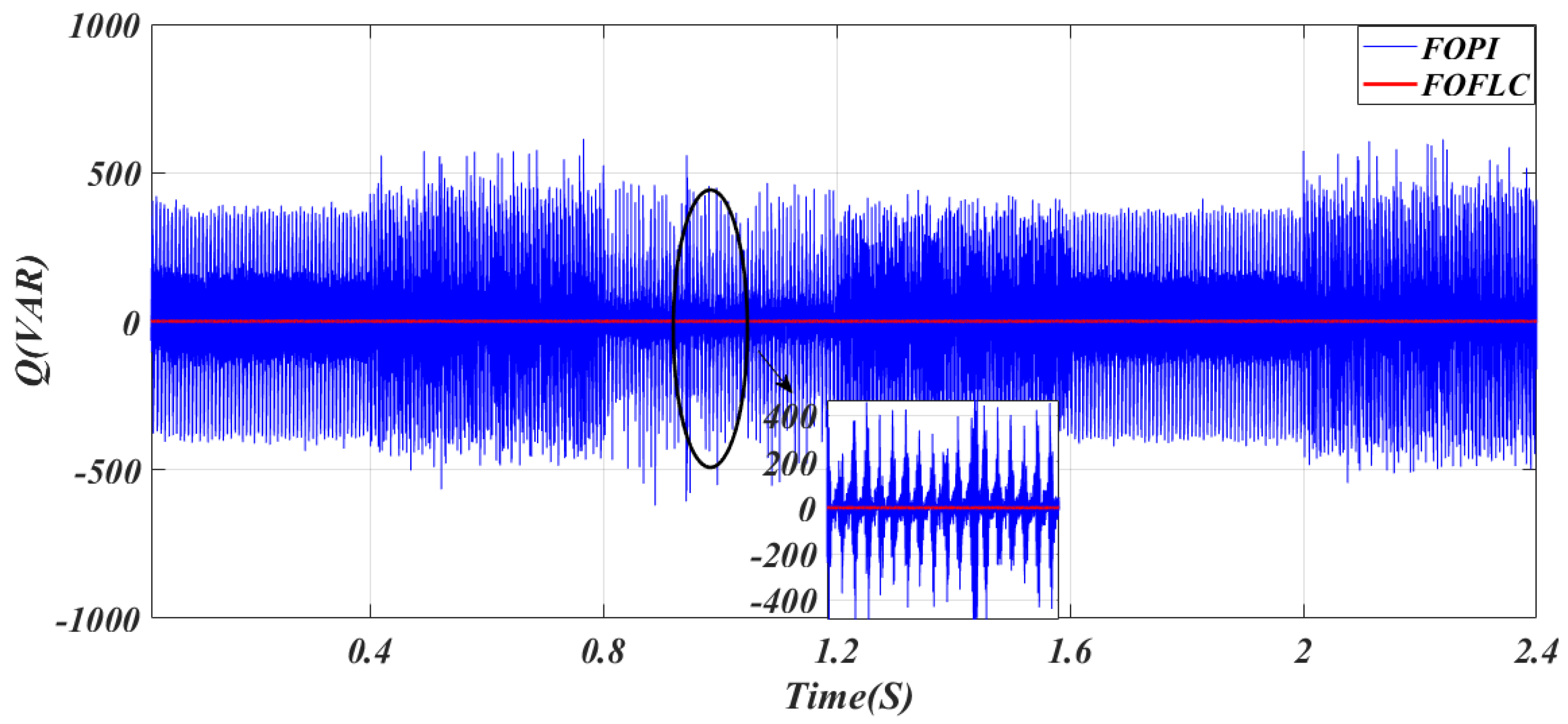
As illustrated in Figure 14, the second test of the two proposed control techniques demonstrates a change in Qs. It is evident from this figure that Qs exhibited a substantial response to variations in system parameters, particularly in scenarios employing the FOPI. This effect is evident in the increase in ripples. The magnitude of these ripples exhibited a marked increase in comparison with the initial test. Conversely, it is observed that the Qs, despite the alteration in system parameters, remain within the designated reference value. The FOFL demonstrates superiority in terms of response time and ripples when compared to the FOPI.
As illustrated in Figure 15, the voltage, current, and THD of current for the two designed controls are represented as system parameters undergo change. This figure demonstrates that despite the system parameter changes, the current and voltage maintain a sinusoidal pattern, identical to the results of the initial test, with the maximum voltage being approximately 52 volts in all cases. Additionally, it is evident that the THD value undergoes transitions from one control state to another due to fluctuations in load demand.
Table 7 compares the harmonic performance of the FOPI and FOFL controllers across six operating modes in Test 2, highlighting their influence on both THD and the fundamental frequency (50 Hz) amplitude. Overall, the FOFL controller consistently achieves lower THD values than the FOPI approach in all operating modes, with reductions ranging from approximately 46.61% to 72.82%. This significant improvement is mainly due to the nonlinear adaptive behavior of the FL method mechanism combined with fractional-order dynamics, which enhances damping of switching-induced harmonics and improves waveform smoothness. In addition, the FOFL method generally reduces the amplitude of the fundamental component in most modes (e.g., Modes 1, 3, 4, 5, and 6), which indicates that the controller not only suppresses harmonic components but also regulates the overall energy content of the output signal more effectively.
However, in Mode 2, an increase in the fundamental amplitude is observed for FOFL compared to FOPI, which is associated with a higher relative reduction in THD (72.82%). This indicates that in this specific operating condition, the FOFL approach improves waveform purity by suppressing harmonic content more aggressively, even if it slightly enhances the fundamental component magnitude. The strong THD reduction in Mode 4 (71.13%) further confirms the effectiveness of FOFL under highly dynamic conditions, where its nonlinear structure provides better compensation for distortions caused by parameter variations or load changes. Overall, the results in Table 7 demonstrate that the FOFL strategy provides superior harmonic mitigation capability and improved PQ compared to the FOPI, while exhibiting some expected variations in fundamental amplitude depending on operating mode and control sensitivity.

4.3. Test 3: Network Voltage Fault

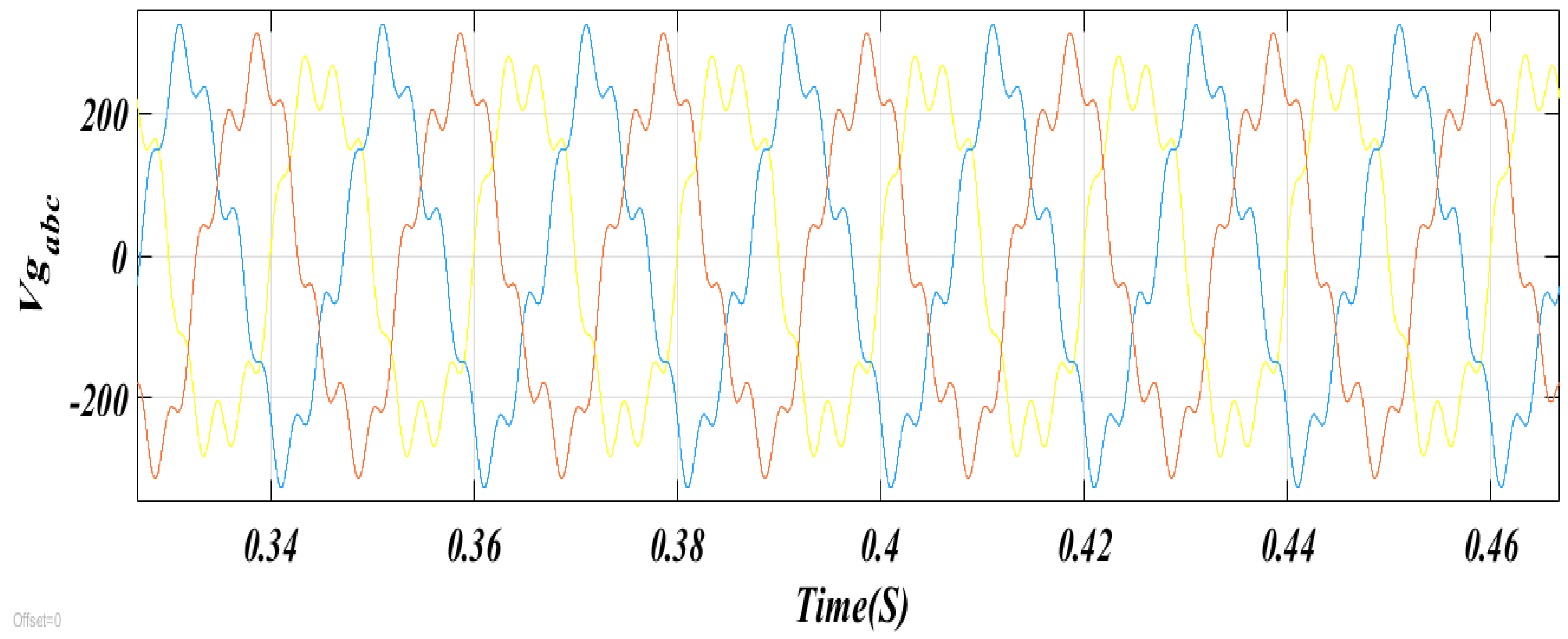
The third test differs from the previous two in that it incorporates a grid voltage disturbance. This disturbance is introduced to evaluate its effect on the performance and behavior of the algorithms proposed in this study. As shown in Figure 16, the grid voltage is used as the basis for assessing the effectiveness and efficiency of the developed methods. The corresponding numerical outcomes are reported in Table 8 and Table 9, while the simulation results are illustrated in Figure 17, Figure 18, Figure 19 and Figure 20.
As illustrated in Figure 17, the variation in the DC bus voltage over time for the two proposed approaches in the third test case is demonstrated. It is evident that the DC bus voltage was considerably influenced by the variation in the mains voltage for both methodologies, with the FOFL demonstrating superiority over the FOPI. This effect is most evident in the increased DC bus voltage ripples, which are significantly lower in the FOFL compared to the FOPI. Conversely, it has been observed that the DC voltage closely follows the reference value, with an overshoot occurring at times 0.4 s, 0.8 s, 1 s, 1.2 s, 1.6 s, and 2 s due to fluctuations in load demand.
The results in Table 8 illustrate the comparative dynamic performance of the FOPI and FOFL control strategies for DC-link voltage regulation under Test 3 conditions. Overall, the FOFL controller demonstrates improved steady-state and transient quality in terms of ripple reduction (33.33%), overshoot reduction (40%), and SSE improvement (16.67%) compared to the FOPI. These improvements can be attributed to the nonlinear and adaptive nature of the FL method combined with fractional-order dynamics, which enhances damping characteristics and provides smoother control action. However, the FOFL strategy exhibits a slightly increased response time (0.065 s versus 0.06 s), corresponding to a minor degradation of 7.69%, which reflects the inherent trade-off between rapid transient response and enhanced signal smoothing introduced by the fractional-order exponent. In practical terms, this marginal delay is the result of stronger attenuation of abrupt control variations, which improves stability but slightly slows convergence. Regarding undershoot behavior at different time instants (0.4 s, 0.8 s, and 2 s), the FOFL controller shows mixed performance, with improvements in some intervals and slight deterioration in others. This variation is expected in nonlinear control systems operating under transient and time-varying conditions, where the FL inference mechanism dynamically adjusts control effort based on error evolution. Despite these localized variations, the overall results confirm that the FOFL strategy provides a more robust and better-damped response, particularly in mitigating voltage ripple and overshoot, which are critical performance indicators in DC-MG applications.
The graphical results in Figure 18 illustrate the dynamic behavior of Ps for both the FOFL and FOPI control strategies under Test 3 conditions, highlighting noticeable differences in transient response and steady-state performance. Overall, the FOFL controller demonstrates a smoother and more stable Ps profile compared to the FOPI approach, with reduced oscillations during both transient and steady-state periods. This improved behavior is mainly due to the nonlinear adaptive nature of the FL method component combined with fractional-order dynamics, which enhances damping and allows more gradual adjustments of the control signal, thereby mitigating abrupt power fluctuations. In contrast, the FOPI controller exhibits relatively higher oscillations and slower stabilization, indicating less effective handling of system nonlinearities and disturbances.
Furthermore, the FOFL strategy reaches steady-state operation more quickly and maintains a more consistent power level, reflecting its superior capability in tracking reference power while minimizing deviations caused by load or system variations. The reduced ripple in the FOFL response also indicates improved PQ and better energy transfer efficiency within the MG system. Overall, Figure 18 confirms that the FOFL controller provides enhanced dynamic performance in Ps regulation, achieving better stability, faster convergence, and improved robustness compared to the conventional FOPI method.
As illustrated in Figure 20, the figure displays the current variation, voltage variation, and current THD for all controls in the event of a fault in the mains voltage. It is evident from this figure that the shape of the current and voltage variation in all cases is influenced by the fault in the mains voltage, as ripples are observed in the current and voltage levels in both techniques. Conversely, it is noteworthy that the THD is also influenced by the fault in the mains voltage for both controls in all cases. The THD values are enumerated in Table 9.
Table 9 presents the harmonic performance of the FOPI and FOFL controllers across six operating cases, highlighting their impact on both the fundamental frequency (50 Hz) component amplitude and THD. Overall, the FOFL strategy achieves a substantial reduction in THD in most cases (Cases 1, 2, and 5), with improvements of 40.68%, 65.75%, and 42.56%, respectively. This performance enhancement is mainly due to the nonlinear mapping capability of the FL controller combined with fractional-order dynamics, which improves waveform smoothness and effectively suppresses harmonic components introduced by switching actions and nonlinear load behavior. In these cases, the FOFL controller also reduces the fundamental component amplitude, indicating a more selective attenuation of high-frequency distortions rather than affecting the fundamental signal quality.
However, in Case 3, FOFL exhibits higher THD compared to FOPI (62.69% vs. 85.08% reduction ratio indicates a degradation trend in the table interpretation), which suggests that under certain operating conditions, the controller tuning leads to less effective harmonic compensation. This may occur when the FL rule base is less sensitive to rapid variations or when fractional-order damping reduces control aggressiveness, allowing residual harmonics to persist. Similarly, Case 4 shows an unusual behavior where the THD ratio becomes negative (−85.31%), indicating a deterioration in harmonic performance, which can be attributed to a stronger suppression of the fundamental component relative to harmonic components, leading to a distorted waveform balance. In contrast, Case 6 shows identical results for both controllers, indicating that under this operating mode, both strategies converge to similar steady-state behavior, likely due to a dominant linear operating region where nonlinear effects are minimal.
Overall, despite some case-dependent variations, the FOFL controller demonstrates superior harmonic mitigation capability in most scenarios, confirming its effectiveness in improving PQ in DC-MG applications, while also highlighting the sensitivity of its performance to operating conditions and controller tuning.
The simulation results confirm the effectiveness of the proposed hybrid MG-connected system. The overall configuration, consisting of WTs, PV units, and battery ESSs, provides a reliable and stable power generation framework. The combined sources are capable of supplying the load demand efficiently. In cases of power shortage, auxiliary sources are utilized to satisfy the demand, while in conditions of excess generation, the surplus energy is either stored in the battery or injected into the AC grid.
In addition to the simulation-based validation, practical implementation aspects of the proposed FOFL control strategy should also be considered. Although the MATLAB 2021a results confirm the method’s effectiveness in reducing harmonics and improving DR, real-time validation is necessary to fully evaluate its performance under non-ideal operating conditions. In practical applications, factors such as computational delays, sensor noise, switching losses, and hardware limitations may affect controller behavior. Nevertheless, the FOFL algorithm is well-suited for real-time implementation due to its relatively low computational complexity and can be deployed using platforms such as dSPACE or digital signal processor (DSP)-based systems. Accordingly, future work will focus on hardware-in-the-loop (HIL) simulations and experimental validation using a laboratory-scale setup to further verify the robustness and effectiveness of the proposed approach under realistic conditions.
Furthermore, the proposed algorithm is compared with existing methods in terms of THD. The comparison is presented in Table 10, based on the results obtained in the first test. In all cases, the proposed method achieves significantly lower THD values compared to several reported approaches in the literature, demonstrating its superiority in improving current quality. As shown in Table 10, the THD values obtained in Case 1 indicate a substantial reduction ranging from 83.33% to 79.40% when compared with the results reported in [103,104,105,106,107,108]. These improvements highlight the effectiveness of the proposed algorithm in enhancing current quality, making it a promising solution for various industrial applications, including electric vehicle systems.
The proposed control framework can be naturally extended to higher power levels through modular and hierarchical MG architectures, which are widely recognized as a key enabler for scalability in modern energy systems. In such structures, individual converter units or local MGs operate as autonomous modules governed by identical or similarly parameterized control laws, while coordination is achieved through a higher-level supervisory or secondary control layer. This hierarchical decomposition allows the same control strategy to be replicated across multiple subsystems without requiring redesign at the megawatt scale, thereby preserving consistency and reducing implementation complexity. Moreover, modular architectures improve fault tolerance and operational flexibility, since each subsystem can continue operating independently in the event of partial system failures. From a scalability perspective, the use of per-unit normalization and decentralized control loops ensures that the proposed algorithm remains largely independent of absolute power ratings, making it applicable from small distributed generation units to large interconnected MGs. Consequently, hierarchical and modular MG configurations significantly enhance the practicality of the proposed control approach in real-world high-power applications by improving robustness, ease of deployment, and expandability.

5. Conclusions

This study investigated the application of the FOFL control strategy in a microgrid-based hybrid power system under variable WS, solar irradiance, and load conditions. The proposed controller was compared with the conventional FOPI approach using key performance indicators such as THD, response time, SSE, and DC-link voltage stability.
Simulation results demonstrated that the FOFL controller significantly enhances system performance and PQ. Compared with the FOPI controller, the proposed method reduced THD by up to 62.84% and decreased DC-link voltage ripples by up to 40%. In addition, the DC bus voltage response time was improved by as much as 81.81%, while the SSE was reduced by up to 50%. The FOFL controller also provided smoother active and reactive power profiles, ensuring stable operation under disturbances and grid faults.
These findings confirm the robustness, reliability, and effectiveness of the FOFL strategy for hybrid renewable energy systems. Although the proposed approach introduces higher computational complexity, its superior dynamic performance and adaptability make it a promising solution for advanced microgrid applications. Future work will focus on intelligent optimization of controller parameters and experimental validation using real-time hardware platforms.

Supplementary Materials

The following supporting information can be downloaded at: https://www.mdpi.com/article/10.3390/a19050418/s1. Figure S1: Structure of the fuzzy logic controller. Figure S2: Membership function of a linguistic variable with seven classes. Table S1: Seven-class inference rule table.

Author Contributions

Conceptualization: K.N.K., H.B., N.B.; Methodology: K.N.K., H.B., N.B.; Software: K.N.K., H.B.; Validation: K.N.K., H.B.; Formal analysis: K.N.K., H.B., N.B.; Investigation: K.N.K., H.B.; Resources: K.N.K., H.B.; Data curation: K.N.K., H.B., N.B.; Writing—original draft preparation: K.N.K., H.B.; Writing—review and editing: K.N.K., H.B., N.B.; Visualization: K.N.K., H.B., N.B.; Supervision: K.N.K., H.B., N.B.; Project administration: K.N.K., H.B.; Funding acquisition: H.B., N.B. All authors have read and agreed to the published version of the manuscript.

Funding

The research was fully supported by the PubArt program of the National University of Science and Technology POLITEHNICA Bucharest, and partially supported by the Experimental—Demonstration project PN-IV-P7-7.1-PED-2024-0567 (Improving the Fuel Cell Hybrid Electric Vehicle Drivetrain by Implementing a Novel Optimal Real-Time Power Management Strategy), contract no. 58PED, 2024-2025.

Institutional Review Board Statement

Not applicable.

Informed Consent Statement

Not applicable.

Data Availability Statement

Data available on request from the authors.

Conflicts of Interest

The authors declare no conflicts of interest.

Nomenclature

PsActive power
FOFLFractional-order fuzzy logic
PIProportional-integral controller
RERenewable energy
MGMicrogrid
PQPower quality
FOPIFractional-order proportional-integral
BHOBlack hole optimization
F/VFrequency and voltage
PWMPulse width modulation
ESSEnergy storage systems
SCSwitched capacitor
WTWind turbine
SSASquirrel search algorithm
QsReactive power
WEWind energy
HPSHybrid power system
PVPhotovoltaics system
SSSCstatic synchronous series compensator
PSOParticle swarm optimization
HDL-RCNNHierarchical deep-learning-based recurrent convolutional neural network
FTCSFixed-time control system
SMCSliding mode control

References

  1. Ahmad, T.; Zhang, D. A critical review of comparative global historical energy consumption and future demand: The story told so far. Energy Rep. 2020, 6, 1973–1991. [Google Scholar] [CrossRef]
  2. Yousuf, A.; Hossain, M.S.; Rahman, M.A.; Karim, A.; Rahman, A. Renewable energy resources in Bangladesh: Prospects, challenges and policy implications. Int. J. Renew. Energy Res. 2022, 12, 1076–1096. [Google Scholar] [CrossRef]
  3. Holechek, J.L.; Geli, H.M.E.; Sawalhah, M.N.; Valdez, R. A global assessment: Can renewable energy replace fossil fuels by 2050? Sustainability 2022, 14, 4792. [Google Scholar] [CrossRef]
  4. Reagan, J.J.M.; Serge, R.D.N.; Patrice, W.; Wulfran, F.M.; Saatong, K.T. Solar irradiance forecasting based on deep learning for sustainable electrical energy in Cameroon. Int. J. Smart Grid 2023, 7, 61–68. [Google Scholar] [CrossRef]
  5. Roy, P.; He, J.; Zhao, T.; Singh, Y.V. Recent advances of wind-solar hybrid renewable energy systems for power generation: A review. IEEE Open J. Ind. Electron. Soc. 2022, 3, 81–104. [Google Scholar] [CrossRef]
  6. Kenu, S.; Uhunmwangho, R.; Okedu, K. Harnessing solar and wind power for hybrid stand-alone energy system: The case of coastline communities in Delta State of Southern Nigeria. Int. J. Smart Grid 2023, 7, 25–37. [Google Scholar]
  7. Wulfran, F.M.; Reagan, J.J.M.; Serge, R.D.N.; Saatong, K.T. A technical analysis of a grid-connected hybrid renewable energy system under meteorological constraints for a timely energy management. Int. J. Smart Grid 2023, 7, 53–60. [Google Scholar] [CrossRef]
  8. Khosravi, N.; Echalih, S.; Hekss, Z.; Baghbanzadeh, R.; Messaoudi, M.; Shahidehpour, M. A new approach to enhance the operation of M-UPQC proportional-integral multiresonant controller based on optimization methods for a stand-alone AC microgrid. IEEE Trans. Power Electron. 2023, 38, 3765–3774. [Google Scholar] [CrossRef]
  9. Khosravi, N.; Dowlatabadi, M.; Sabzevari, K. A hierarchical deep learning approach to optimizing voltage and frequency control in networked microgrid systems. Appl. Energy 2025, 377, 124313. [Google Scholar] [CrossRef]
  10. Nima, K. Finite-time control scheme for effective voltage and frequency regulation in networked microgrids. Int. J. Electr. Power Energy Syst. 2025, 165, 110481. [Google Scholar] [CrossRef]
  11. Nima, K. Enhancing operational efficiency through a control-based approach for hydrogen and battery energy storage systems integration in renewable energy. Renew. Energy 2025, 248, 123132. [Google Scholar] [CrossRef]
  12. Ram, A.; Sharma, P.R.; Ahuja, R.K.; Arya, Y. A dual fundamental current extraction controller for DSTATCOM in distribution system for power quality improvement. Electr. Power Compon. Syst. 2023, 1–24. [Google Scholar] [CrossRef]
  13. Gopal, Y.; Kumari, A.; Panda, K.P.; Dhaked, D.K.; Arya, Y. Implementation and analysis of switched-capacitor multilevel inverters in solar photovoltaic system. Sustain. Energy Technol. Assess. 2025, 75, 104227. [Google Scholar] [CrossRef]
  14. Gopal, Y.; Panda, K.P.; Gupta, P.P.; Dhaked, D.K.; Arya, Y. Development and performance assessment of switched-capacitor multilevel inverters for solar PV applications. Sustain. Energy Technol. Assess. 2025, 79, 104360. [Google Scholar] [CrossRef]
  15. Nahak, N.; Bohidar, S.; Mallick, R.K. Assessment and damping of low-frequency oscillations in hybrid power system due to random renewable penetrations. Int. J. Renew. Energy Res. 2020, 10, 1907–1918. [Google Scholar] [CrossRef]
  16. Elsayed, Y.; Saad, N.H.; Zekry, A. Assessing wind energy conversion systems based on newly developed wind turbine emulator. Int. J. Smart Grid 2020, 4, 139–148. [Google Scholar] [CrossRef]
  17. Caglayan, R.Z.; Kayisli, K.; Zhakiyev, N.; Harrouz, A.; Colak, I. A review of hybrid renewable energy systems and MPPT methods. Int. J. Smart Grid 2022, 6, 72–78. [Google Scholar] [CrossRef]
  18. Vu, N.A.; Pham, N.S. Analytical methodology for aerodynamic analysis of vertical axis wind turbine. Int. J. Renew. Energy Res. 2020, 10, 1145–1153. [Google Scholar] [CrossRef]
  19. Supreeth, R.; Arokkiaswamy, A.; Nagarjun Raikar, J.; Prajwal, H.P. Experimental investigation of small scale horizontal axis wind turbine rotor blade. Int. J. Renew. Energy Res. 2019, 9, 1983–1994. [Google Scholar] [CrossRef]
  20. Ayodele, T.R.; Jimoh, A.; Munda, J.L.; Tehile, A.J. Challenges of grid integration of wind power on power system grid integrity: A review. Int. J. Renew. Energy Res. 2012, 2, 618–626. [Google Scholar]
  21. Elkodama, A.; Ismaiel, A.; Abdellatif, A.; Shaaban, S. Aerodynamic performance and structural design of 5 MW multi rotor system wind turbines. Int. J. Renew. Energy Res. 2022, 12, 1495–1505. [Google Scholar] [CrossRef]
  22. Erturk, E.; Sivrioglu, S.; Bolat, F.C. Analysis model of a small scale counter-rotating dual rotor wind turbine. Int. J. Renew. Energy Res. 2018, 8, 1849–1858. [Google Scholar] [CrossRef]
  23. Kumar, A.S.; Kishore, D.R.; Kumar, K.P.; Sriram, S.; Vamsi, P. Whale optimization-based PI control for DFIG wind energy systems. Int. J. Smart Grid 2025, 9, 94–104. [Google Scholar] [CrossRef]
  24. Mazouz, F.; Belkacem, S.; Colak, I. DPC-SVM of DFIG using fuzzy second order sliding mode approach. Int. J. Smart Grid 2021, 5, 174–182. [Google Scholar] [CrossRef]
  25. Meng, Y.; Zhang, L.; Xu, G.; Wang, H. Direct-current generators based on conductive polymers for self-powered flexible devices. Sci. Rep. 2021, 11, 20258. [Google Scholar] [CrossRef]
  26. Salem, A.A.; Aldin, N.A.N.; Azmy, A.M.; Abdellatif, W.S.E. A fuzzy logic-based MPPT technique for PMSG wind generation system. Int. J. Renew. Energy Res. 2019, 9, 1751–1760. [Google Scholar] [CrossRef]
  27. Waqas, A.B. Grid connected wind energy conversion system for peak load sharing using fuzzy logic controller. Int. J. Renew. Energy Res. 2017, 7, 1767–1778. [Google Scholar] [CrossRef]
  28. Vasudevan, K.R.; Ramachandaramurthy, V.K.; Venugopal, G.; Ekanayake, J.; Tiong, S. Variable speed pumped hydro storage: A review. Renew. Sustain. Energy Rev. 2021, 135, 110156. [Google Scholar] [CrossRef]
  29. EL Makrini, A.; EL Karkri, Y.; Boukhriss, Y.; Elmarkhi, H.; EL Moussaoui, H. LVRT control strategy of DFIG wind turbines. Int. J. Renew. Energy Res. 2017, 7, 1258–1269. [Google Scholar] [CrossRef]
  30. Putri, R.I.; Rifai, M.; Syamsiana, I.N.; Ronilaya, F. Control of PMSG stand-alone wind turbine system based on multi-objective PSO. Int. J. Renew. Energy Res. 2020, 10, 998–1004. [Google Scholar]
  31. Atherton, D.L. Superconducting DC generators and motors. IEEE Spectr. 1964, 1, 67–71. [Google Scholar] [CrossRef]
  32. Belkaid, A.; Colak, I.; Kayisli, K.; Bayindir, R. Modeling of a permanent magnet synchronous generator in a wind power generation system with an electrochemical energy storage. Int. J. Smart Grid 2018, 2, 197–202. [Google Scholar] [CrossRef]
  33. Louar, F.; Ouari, A.; Omeiri, A.; Senani, F.; Rahab, A. Direct power control (DPC) of PMSG-based wind energy conversion system. In Proceedings of the 4th International Conference on Electrical Engineering (ICEE), Boumerdes, Algeria, 13–15 December 2015; pp. 1–6. [Google Scholar] [CrossRef]
  34. Toumi, S.; Amirat, Y.; Trabelsi, M.; Elbouchikhi, E.; Mimouni, M.F.; Benbouzid, M.E.H. Backstepping control of a PMSG-based marine current turbine system under faulty conditions. In Proceedings of the 9th International Conference on Renewable Energy (IREC), Hammamet, Tunisia, 12–15 November 2018; pp. 1–6. [Google Scholar] [CrossRef]
  35. Nguyen, H.M. A comparative study of different sliding mode control strategies for PMSG-based standalone WECS. Int. J. Renew. Energy Res. 2021, 11, 1977–1986. [Google Scholar] [CrossRef]
  36. Allouche, M.; Abderrahim, S.; Ben Zina, H.; Chaabane, M. A novel fuzzy control strategy for maximum power point tracking of wind energy conversion system. Int. J. Smart Grid 2019, 3, 120–127. [Google Scholar] [CrossRef]
  37. Liang, J.; Whitby, B. Field oriented control of a permanent magnet synchronous generator for use in a variable speed tidal stream turbine. In Proceedings of the 46th International Universities’ Power Engineering Conference (UPEC), Soest, Germany, 5–8 September 2011; pp. 1–6. [Google Scholar]
  38. Hasnaoui, O.; Mehdi, A.; Belhadj, J. Direct drive wind turbine equipped with an active and reactive power supervisory. Int. J. Renew. Energy Res. 2014, 4, 435–444. [Google Scholar]
  39. Goud, S.; Gowd, N.R. Power quality enhancement in PV-fed UPQC using adaptive lizard algorithm. Int. J. Smart Grid 2025, 9, 31–42. [Google Scholar] [CrossRef]
  40. Rao, N.L.; Somalwar, R.; Joshi, K.; Subudhi, P.S. An improved MPPT algorithm for performance improvement of 50 kW grid-connected PV system. Int. J. Smart Grid 2025, 9, 1–8. [Google Scholar] [CrossRef]
  41. Chakole, N.; Remamany, K.P.; Mohan, G.; Sasirekha, P.; Kumar, N.; Kumar, C.R.; Shunmugasundaram, M.; Alagarsamy, M.; Ganthia, B.P. Optimal energy management for hybrid PV–wind–battery microgrids through Markov decision processes. Int. J. Smart Grid 2025, 9, 127–145. [Google Scholar] [CrossRef]
  42. Saab, K.; Tarnini, M.; El Ghaly, A. A power electronic controller-based algorithm for output power prediction of a PV panel. Int. J. Renew. Energy Res. 2023, 13, 1194–1199. [Google Scholar] [CrossRef]
  43. Jaber, S.F.; Shakir, A.M. Design and simulation of a boost-microinverter for optimized photovoltaic system performance. Int. J. Smart Grid 2021, 5, 94–102. [Google Scholar] [CrossRef]
  44. Patidar, A.; Dubey, V.K.; Sarvate, D. Design and development of solar-based fast charger for E-vehicle using MPPT algorithm. Int. J. Renew. Energy Res. 2024, 14, 363–369. [Google Scholar] [CrossRef]
  45. Mohamed, S.; Abd El Sattar, M. A comparative study of P&O and INC maximum power point tracking techniques for grid-connected PV systems. SN Appl. Sci. 2019, 1, 174. [Google Scholar] [CrossRef]
  46. Swaminathan, B.; Selvi, S.; Jothilakshmi, R.; Kirubakaran, D.; Rajaram, A. Performance optimization of an interleaved boost converter with water cycle optimized PO algorithm-based MPPT. Int. J. Renew. Energy Res. 2024, 14, 248–260. [Google Scholar] [CrossRef]
  47. Massaq, Z. Design of high-performance fuzzy–predictive controllers for a photovoltaic/battery pumping system. Int. J. Renew. Energy Res. 2023, 13, 442–453. [Google Scholar] [CrossRef]
  48. Fadi, O.; Abbou, A.; Mahmoudi, H.; Gaizen, S. Optimized MPPT for aero-generator system using feed-forward neural network. Int. J. Renew. Energy Res. 2023, 13, 1134–1144. [Google Scholar] [CrossRef]
  49. Soma, K.S.; Balamurugan, R.; Karuppiah, N. Two-stage PV generation system with novel control strategy under partial shading. Int. J. Renew. Energy Res. 2024, 14, 437–449. [Google Scholar] [CrossRef]
  50. Maniraj, B.; Fathima, A.P.; Morris, S. PV output power enhancement using meta-heuristic crow search algorithm. Int. J. Renew. Energy Res. 2023, 13, 117–124. [Google Scholar] [CrossRef]
  51. Caglayan, R.Z.; Kayisli, K.; Roscia, M.; Belkaid, A.; Nasri, A. Comparative analysis of MPPT methods for PV and fuel cell hybrid system. Int. J. Renew. Energy Res. 2023, 13, 1431–1442. [Google Scholar] [CrossRef]
  52. Boussafa, A.; Ferfra, M.; Rabeh, R.; Chennoufi, K. Genetic algorithm-based backstepping controller for MPPT under partial shading. Int. J. Renew. Energy Res. 2024, 14, 526–537. [Google Scholar] [CrossRef]
  53. El Ouardi, H.; Mokhlis, M.; El Gadari, A.; Ounejjar, Y.; Bejjit, L. ANN-robust backstepping MPPT with high gain observer. Int. J. Renew. Energy Res. 2023, 13, 1332–1341. [Google Scholar] [CrossRef]
  54. Pandey, N.K.; Pachauri, R.K.; Choudhary, S.; Thanikanti, S.B. Frequency locked loop-based control for PV-battery integrated system. Int. J. Renew. Energy Res. 2024, 14, 155–165. [Google Scholar] [CrossRef]
  55. Selvi, S.; Jayarama, P.; Sri Harsha, A.; Rajesh, T.; Elangovan, P.; Ramprasad, R.M.; Sivasankar, G.A.; Rajaram, A. Energy storage systems for grid-integrated renewable systems. Int. J. Renew. Energy Res. 2024, 14, 166–175. [Google Scholar] [CrossRef]
  56. Sharma, S.; Niazi, K.R.; Verma, K.; Rawat, T. Impact of multiple battery energy storage systems on distribution network losses. Int. J. Renew. Energy Res. 2019, 9, 1705–1711. [Google Scholar] [CrossRef]
  57. Adams, E.; Camacho, A.; Mammana, E.; Kim, S.; Adams, T.E.; Pol, V.G. Efficient photovoltaics integrated with Li-ion batteries for extreme temperature operation. Sci. Rep. 2025, 15, 10190. [Google Scholar] [CrossRef] [PubMed]
  58. Grami, M. Power dispatch strategy for interconnected microgrids. Int. J. Renew. Energy Res. 2018, 8, 838–850. [Google Scholar] [CrossRef]
  59. Raghavendra, L.; Parthasarathy, L. Power quality analysis in microgrids using wavelet transform. Int. J. Renew. Energy Res. 2024, 14, 794–803. [Google Scholar]
  60. Ahmed, S.; Ali, A.; D’Angola, A. A review of renewable energy communities. Sustainability 2024, 16, 1749. [Google Scholar] [CrossRef]
  61. Raza, M.U.; Raza, I.; Maqbool, Z.; Masih, B.; Iqbal, F. An overview of DC circuit breaker topologies in DC microgrids. Int. J. Smart Grid 2023, 7, 178–188. [Google Scholar] [CrossRef]
  62. Nguyen, H.V.P.; Nguyen, V.H. A combined strategy to improve operational efficiency of microgrids with high integration of solar and wind energy. Int. J. Renew. Energy Res. 2024, 13, 1247–1258. [Google Scholar] [CrossRef]
  63. Adel, G. Data monitoring and performance analysis of a 1.6 kWp grid-connected PV system in Algeria. Int. J. Renew. Energy Res. 2016, 6, 34–42. [Google Scholar] [CrossRef]
  64. Khallouf, K.N.; Zarour, L.; Bouziane, M.; Debdouche, N. Hybrid renewable energy system control comprising wind turbine, PV panels, and battery storage. In Proceedings of the 1st International Conference on Electrical, Computer, Telecommunication and Energy Technologies (ECTE-Tech), Oum El Bouaghi, Algeria, 17–18 December 2024; pp. 1–7. [Google Scholar] [CrossRef]
  65. Vukojičić, S.; Pavlović, S.; Ristić, L. Passive, active and hybrid filters in energy-efficient electrical drives curriculum. In Proceedings of the 20th International Symposium on Power Electronics (Ee), Novi Sad, Serbia, 14–16 June 2019; pp. 1–6. [Google Scholar] [CrossRef]
  66. Bielecka, A.; Wojciechowski, D. Stability Analysis of Shunt Active Power Filter with Predictive Closed-Loop Control of Supply Current. Energies 2021, 14, 2208. [Google Scholar] [CrossRef]
  67. Boopathi, R.; Indragandhi, V. Power quality enhancement using predictive direct power control for PV-interfaced multilevel inverter SAPF. Sci. Rep. 2025, 15, 7967. [Google Scholar] [CrossRef]
  68. Boudechiche, G.; Aissa, O.; Sarra, M.; Hatti, M.; Belkhiri, S. SAPF interconnected to PV system based on DPC with disturbance rejection. In Proceedings of the ICARES 2022; Springer: Berlin/Heidelberg, Germany, 2024. [Google Scholar] [CrossRef]
  69. Rath, A.; Srungavarapu, G. Model predictive and DPC-based SAPFs. In Proceedings of the ICPEE, Bhubaneswar, India, 2–3 January 2021; pp. 1–6. [Google Scholar] [CrossRef]
  70. Ouchen, S.; Benbouzid, M.; Blaabjerg, F.; Betka, A.; Steinhart, H. DPC of SAPF using space vector modulation and supertwisting sliding mode control. IEEE J. Emerg. Sel. Top. Power Electron. 2021, 9, 3243–3253. [Google Scholar] [CrossRef]
  71. Rath, A.; Srungavarapu, G. Advanced SAPF for non-ideal grid using predictive DPC. IETE Tech. Rev. 2023, 40, 521–534. [Google Scholar] [CrossRef]
  72. Sidik, A.D.W.M.; Efendi, E.; Lumbantobing, H.; Indrawan, B.; Junfithrana, A.P.; Ula, R.K.; Suryana, A.; Tambunan, H.B.; Narputro, P.; Artiyasa, M. Interval type-2 fuzzy logic controller for SAPF. J. Tek. Elektro 2024, 6, 177–187. [Google Scholar] [CrossRef]
  73. Maroua, B.; Laid, Z.; Benbouhenni, H.; Elbarbary, Z.M.S.; Colak, I.; Alammar, M.M. Genetic algorithm type-2 fuzzy logic controller for microgrid system. Sci. Rep. 2025, 15, 6318. [Google Scholar] [CrossRef]
  74. Debdouche, N.; Deffaf, B.; Benbouhenni, H.; Laid, Z.; Mosaad, M.I. DPC for three-level inverter PV system using simplified super-twisting algorithm. Energies 2023, 16, 4103. [Google Scholar] [CrossRef]
  75. Debdouche, N.; Chebabhi, A.; Benbouhenni, H.; Hadjaidji, F.-Z.; Elbarbary, Z.M.S.; Al-Gahtani, S.F. Synergetic super-twisting control for PV/BESS DC microgrid stability. Sci. Rep. 2025, 15, 7392. [Google Scholar] [CrossRef]
  76. Acharya, D.P.; Nayak, N.; Choudhury, S.; Padhy, R. Power quality improvement in fuel-cell microgrid using SAPF. Int. J. Renew. Energy Res. 2020, 10, 1071–1082. [Google Scholar] [CrossRef]
  77. Meraouah, M.; Kaddari, F.; Hassaine, S.; Mihoub, Y.; Heroual, S.; Khenfar, N. Predictive DPC of SAPF with ANN-backstepping MPPT. Alger. J. Renew. Energy Sustain. Dev. 2024, 6, 109–118. [Google Scholar]
  78. Khallouf, K.N.; Laid, Z.; Benbouhenni, H.; Debdouche, N.; Elbarbary, Z. Adaptive fuzzy logic control for hybrid PV/wind systems. Energy Rep. 2024, 12, 4741–4756. [Google Scholar] [CrossRef]
  79. Hadjaidji, F.-Z.; Boukhetala, D.; Debdouche, N.; Benbouhenni, H.; Barbot, J.-P.; Zarour, L. Fractional-order terminal super-twisting control for PV systems. Energy Rep. 2024, 12, 5024–5043. [Google Scholar] [CrossRef]
  80. Chaoui, A.; Krim, F.; Gaubert, J.-P.; Rambault, L. DPC-controlled three-phase active filter for power quality. Int. J. Electr. Power Energy Syst. 2008, 30, 476–485. [Google Scholar] [CrossRef]
  81. Habib, B.; Abdessmad, M.; Zakaria, M.S.E.; Ilhami, C.; Nicu, B.; Arafath, M.S. Experimental Verification of the Performance of a Nonlinear Regulator Based on Genetic Algorithms in Improving the Power Quality of DFIG. Int. Trans. Electr. Energy Syst. 2026, 2026, 2186135. [Google Scholar] [CrossRef]
  82. Deffaf, B.; Farid, H.; Benbouhenni, H.; Medjmadj, S.; Debdouche, N. Synergetic control for three-level inverter SAPF. Energy Rep. 2023, 10, 1013–1027. [Google Scholar] [CrossRef]
  83. Abdelmalek, F.; Afghoul, H.; Krim, F.; Zabia, D.E.; Krim, S.A.; Bouzidi, B.M.N.; Ouchen, L.; Boukhdanna, A.E. Experimental DPC implementation for SAPF with PI controller tuned using grey wolf optimization. In Proceedings of the 2024 International Conference on Advances in Electrical and Communication Technologies (ICAECOT), Setif, Algeria, 1–3 October 2024; pp. 1–6. [Google Scholar] [CrossRef]
  84. Rami Reddy, C.; Prakash, R.B.R.; Srinivasa, V.P.; Dilip Kumar, M.; Giri Prasad, A.; Shiva Prasad, E. MPPT for PMSG wind park applications. Int. J. Renew. Energy Res. 2022, 12, 846–862. [Google Scholar]
  85. Abderrahim, S.; Allouche, M.; Chaabane, M. Robust control strategy for wind energy system based on T-S fuzzy model. Int. J. Smart Grid 2020, 4, 88–99. [Google Scholar] [CrossRef]
  86. Harrabi, N.; Souissi, M.; Aitouche, A.; Chabaane, M. Intelligent control of PMSG wind system using T-S fuzzy scheme. Int. J. Renew. Energy Res. 2015, 5, 952–960. [Google Scholar] [CrossRef]
  87. Okedu, K.; AlSenaidi, A.S.; Al Hajri, I.; Al Rashdi, I.; Al Salmani, W. Real-time dynamic analysis of PV integration. Int. J. Smart Grid 2020, 4, 68–79. [Google Scholar] [CrossRef]
  88. Hamzeh, A.; Hamid, S.; Al-Omari, Z.A.; Sandouk, A.; Aldahim, G. PV plant performance in Jordan. Int. J. Renew. Energy Res. 2015, 5, 983–990. [Google Scholar] [CrossRef]
  89. Popavath, L.N.; Palanisamy, K. PV-STATCOM for reactive power compensation and power injection. Int. J. Renew. Energy Res. 2015, 5, 973–982. [Google Scholar] [CrossRef]
  90. Akil, M.; Dokur, E.; Bayindir, R. EV charging scheduling with PV system. Int. J. Smart Grid 2022, 6, 65–71. [Google Scholar] [CrossRef]
  91. Davidson, I.E.A.; Buraimoh, E. PV-based microgrid modeling and fault ride-through control. Int. J. Smart Grid 2023, 7, 69–83. [Google Scholar] [CrossRef]
  92. Bhuyan, K.C.; Pattanaik, S.; Samal, S. Performance analysis of a fuel cell connected to a DC–DC boost converter. Int. J. Renew. Energy Res. 2024, 14, 879–889. [Google Scholar] [CrossRef]
  93. Coteli, R.; Caglayan, R.Z.; Kayisli, K. Energy management based on supertwisting sliding mode in standalone photovoltaic power system with battery backup. Int. J. Smart Grid 2024, 8, 191–198. [Google Scholar] [CrossRef]
  94. Ishiyama, T. Correlation assessment between indoor photovoltaic energy harvesting and storage characteristics. Int. J. Smart Grid 2022, 6, 123–127. [Google Scholar] [CrossRef]
  95. Pradhan, R.; Panda, A. Modeling and simulation of an MPC-based grid-tied PVDG system. Int. J. Renew. Energy Res. 2022, 12, 422–432. [Google Scholar] [CrossRef]
  96. Senapati, R. Performance analysis of three-phase shunt active filter in grid-tied PV–fuel cell system. Int. J. Renew. Energy Res. 2018, 8, 67–81. [Google Scholar] [CrossRef]
  97. Krishna, D.; Sasikala, M.; Kiranmayi, R. FOPI and FOFL controller based UPQC for power quality mitigation. J. Electr. Eng. Technol. 2022, 17, 1543–1554. [Google Scholar] [CrossRef]
  98. Benbouhenni, H.; Yahdou, A.; Elbarbary, Z.M.S.; Djilali, A.B.; Colak, I.; Al-Gahtani, S.F. Power management in wind turbine systems using fuzzy fractional-order control. Sci. Rep. 2025, 15, 12696. [Google Scholar] [CrossRef] [PubMed]
  99. Soomro, D.M.; Chong, S.C.; Memon, Z.A.; Uqaili, M.A.; Abbasi, F. Performance of shunt active power filter based on instantaneous reactive power Control theory. Int. J. Renew. Energy Res. 2017, 7, 1741–1751. [Google Scholar] [CrossRef]
  100. Ouchen, S.; Steinhart, H.; Benbouzid, M.; Blaabjerg, F. Robust DPC-SVM control strategy for shunt active power filter based on H∞ regulators. Int. J. Electr. Power Energy Syst. 2020, 117, 105699. [Google Scholar] [CrossRef]
  101. Saidi, S.; Abbassi, R.; Chebbi, S. VF-DPC-SVM controlled three-phase shunt active filter. In Proceedings of the 2015 IEEE 12th International Multi-Conference on Systems, Signals & Devices (SSD15); IEEE Xplore: Piscataway, NJ, USA, 2015. [Google Scholar]
  102. Debdouche, N.; Chebabhi, A.; Ouchen, S.; Zarour, L. Direct power control of three-level SAPF using space vector modulation. In Proceedings of the 2022 19th International Multi-Conference on Systems, Signals & Devices (SSD); IEEE Xplore: Piscataway, NJ, USA, 2022. [Google Scholar]
  103. Das, S.; Akella, A.K. Power flow control of PV–wind–battery hybrid system for standalone application. Int. J. Renew. Energy Res. 2018, 8, 36–43. [Google Scholar] [CrossRef]
  104. Roy, T.K.; Mahmud, M.A.; Oo, A.M.T.; Bansal, R.; Haque, M.E. Nonlinear adaptive backstepping control for grid-connected PV systems. Electr. Power Compon. Syst. 2018, 45, 2275–2292. [Google Scholar] [CrossRef]
  105. Albalawi, H.; El-Shimy, M.E.; AbdelMeguid, H.; Kassem, A.M.; Zaid, S.A. Hybrid wind/PV system using brain emotional learning controller. Sustainability 2022, 14, 4775. [Google Scholar] [CrossRef]
  106. Bekakra, Y.; Zellouma, L.; Malik, O. Improved predictive DPC of SAPF using GWO and ALO. Ain Shams Eng. J. 2021, 12, 3859–3877. [Google Scholar] [CrossRef]
  107. Boudechiche, G.; Sarra, M.; Aissa, O.; Gaubert, J.-P.; Benlahbib, B.; Lashab, A. Anti-windup FOPID-based DPC for SAPF tuned using PSO. Eur. J. Electr. Eng. 2020, 22, 313–324. [Google Scholar] [CrossRef]
  108. Al-Quraan, A.; Al-Qaisi, M. Design and control of standalone hybrid PV–wind microgrid system. Energies 2021, 14, 4849. [Google Scholar] [CrossRef]
  109. Bandahalli Mallappa, P.K.; Martínez-García, H.; Velasco-Quesada, G. Power quality improvement in grid-connected PV system using hybrid technology. Renew. Energy Power Qual. J. 2021, 19, 316–320. [Google Scholar] [CrossRef]
Figure 1. Block diagram of the designed HPS.
Algorithms 19 00418 g001
Figure 2. The internal structure of the studied control system.
Algorithms 19 00418 g002
Figure 3. Coefficient Cp characteristics.
Algorithms 19 00418 g003
Figure 4. FOPI approach.
Algorithms 19 00418 g004
Figure 5. FOFL approach.
Algorithms 19 00418 g005
Figure 6. DPC-SVM technique with FOFL controller or FOPI controller.
Algorithms 19 00418 g006
Figure 7. Variable WS, irradiance, and load demand profiles [78].
Algorithms 19 00418 g007
Figure 8. Power flow distribution (Test 1).
Algorithms 19 00418 g008
Figure 9. DC link voltage of both algorithms (Test 1).
Algorithms 19 00418 g009
Figure 10. Current and voltage curve and THD (Test 1).
Algorithms 19 00418 g010aAlgorithms 19 00418 g010b
Figure 11. Reactive power on the grid side (Test 1).
Algorithms 19 00418 g011
Figure 12. DC bus voltage of both methods (Test 2).
Algorithms 19 00418 g012
Figure 13. Active power of both techniques (Test 2).
Algorithms 19 00418 g013
Figure 14. Reactive power on the grid side of both approaches (Test 2).
Algorithms 19 00418 g014
Figure 15. Voltage and current curve and THD (Test 2).
Algorithms 19 00418 g015aAlgorithms 19 00418 g015b
Figure 16. Grid voltage profile.
Algorithms 19 00418 g016
Figure 17. DC bus voltage of both strategies (Test 3).
Algorithms 19 00418 g017
Figure 18. Active power of both techniques (Test 3).
Algorithms 19 00418 g018
Figure 19. Reactive power on the grid side (Test 3).
Algorithms 19 00418 g019
Figure 20. Voltage and current curve and THD (Test 3).
Algorithms 19 00418 g020aAlgorithms 19 00418 g020b
Table 1. Disadvantages and advantages of some generators.
GeneratorsAvantagesDesadvantages
Doubly-fed induction machine [28]• Can operate at varying speeds while maintaining consistent power output.
• Less losses compared to other power systems.
• Requires a sophisticated control system to manage speed and torque.
• Power electronics can be expensive to install and maintain.
DFIG [29]• Allows good control of energy production.
• Can operate at varying WSs while maintaining a constant frequency.
• Requires sophisticated converters and control systems.
• Power electronics components may require more maintenance.
• Less efficient at low speeds compared to PMSG.
PMSG [30]• PMSGs have higher efficiency, especially at high loads.
• Fewer components (no wound rotor), which reduces maintenance.
• Effective even at lower rotation speeds, which is ideal for WTs.
• Less electrical losses thanks to the absence of excitation current.
• Permanent magnets, often made with rare earth, can be expensive.
• Power control can be complex in certain conditions.
DC generators [31]• Avoid the large input cables required to transport heavy electrical currents from external sources to superconducting devices.
• Reduce power losses.
• Ease of control.
• They provide smoother voltage compared to some other types of generators.
• These generators face limitations in transmitting power over long distances.
• The difficulty of converting power using transformers.
Table 2. Parameters of the studied system [72,73,78].
DC Side Hybrid RE System
Vg230 V
Lg2.5 mH
Rg0.01 Ω
f50 Hz
Vdc*800 V
Wind turbine
R4.4 m
PWt20 kW
PMSG
Rs0.1764 W
ns211 rpm
Ld and Lq4.48 mH
Pe20 kW
Pv array
Vmp34.5 V
Isc4.35 A
Voc43.5 V
Imp4.35 A
Gref1000 W/m2
Pmp150 W
Tref25 °C
Li ion battery system
Battery converter resistance0.05 Ω
Rated capacitor100 Ah
Battery converter inductance1 mH
Vn400 V
Battery converter capacitance4000 μF
Nonlinear load
Inductance83.2 mH
Resistance51.64 Ω
Table 3. Control gain values [78].
FOPIFOFL
PV system (MPPT)
Integral = 150
Proportional = 5
Wind turbine (MPPT)
Ki = 700
Kp = 500
DPC
Integral = 2
Proportional = 0.01
α = 3.51
Storage system
Integral = 16
Proportional = 0.33
PV system (MPPT)
KdD = 20
Kde = 0.5
Ke = 0.1
Wind turbine (MPPT)
Ke = 1000
Kde = 5,000,000
KdD = 1000
DPC
KDd = 3800
Ke = 0.0002*1.25
α = 1.28
Kde = 0.0002
Storage system
Kde = 0.01
Ke = 0.01
KdD = 2100
Table 4. Numerical results of DC link voltage (Test 1).
ParametersApproachesRatios (%)
FOPIFOFL
Ripples (V)0.20.1240
Overshoot (%)0.500.37525
Response time (s)0.0550.01581.81
SSE(V)0.10.0550
Undershoot (%)0.4 s1.251.12510
0.8 s0.750.533.33
2 s1.751.5610.86
Table 5. THD values in the six cases for both techniques (Test 1).
CasesTHD (%)FS (50 Hz) Amplitude (A)Ratios (%)
FOFLFOPIFOFLFOPITHDFS (50 Hz) Amplitude
Case 10.751.4213.8022.2147.18−37.87
Case 20.470.7914.6113.7440.515.95
Case 30.350.3919.6124.9710.26−21.47
Case 40.502.3113.844.06978.3570.60
Case 50.561.1819.1226.3152.54−27.33
Case 60.330.3828.9932.6613.16−11.24
Table 6. Numerical results of the DC link voltage of both approaches (Test 2).
ParametersMethodsRatios (%)
FOPIFOFL
Ripples (V)0.0250.01540
Overshoot (%)10.550
Response time (s)0.060.03246.67
SSE(V)0.0820.0626.83
Undershoot (%)0.4 s1.381.12518.48
0.8 s0.8750.75014.29
2 s1.9401.63015.98
Table 7. THD values in the six cases for both techniques (Test 2).
ModesTHD (%)FS (50 HZ) Amplitude (A)Ratios (%)
FOPIFOFLFOPIFOFLFS (50 HZ) Amplitude (A)THD
Mode 11.480.5527.5516.60−39.7562.84
Mode 23.791.038.77411.82+25.7772.82
Mode 31.180.6319.5416.85−13.7746.61
Mode 43.360.9734.4811.11−67.7871.13
Mode 51.360.4431.7522.89−27.9167.65
Mode 61.420.6527.2119.09−29.8454.23
Table 8. Numerical results of DC link voltage of both strategies (Test 3).
ParametersApproachesRatios (%)
FOPIFOFL
Ripples (V)6433.33
Overshoot (%)10640
Response time (s)0.060.065−7.69
SSE(V)0.120.116.67
Undershoot (%)0.4 s0.8751.125−22.22
0.8 s1.1250.81327.73
2 s1.4401.690−14.79
Table 9. THD values in the six cases for both techniques (Test 3).
ModesFS (50 HZ) amplitude (A)THD (%)Ratios (%)
FOPIFOFLCFOPIFOFLFS (50 HZ) amplitudeTHD
Case 129.3616.903.221.91−42.4440.68
Case 28.6684.258113.7338.95−50.8865.75
Case 31.5673.96385.0862.69+60.4626.32
Case 49.9352.90316.09109.50−70.78−85.31
Case 534.4822.643.361.93−34.3442.56
Case 619.8519.8512.2312.2300
Table 10. A comparative study with related works in terms of the value of current THD.
ReferencesMicro-Grid ComponentsTHD (%)
[78]PV/WE/BatteryPI control3.06
Adaptive FL2.76
[103]WE/PV/Battery/Dump DC load/AC loads4.5
[104]PV/Grid2.89
[105]WE/PV/Battery/Standalone2.22
[106]SAPF/Grid3.40
5.70
2.80
[107]2.35
1.90
[108]PV/Battery/WE/Standalone5
[109]PV/Utility grid3.64
Designed strategy PV/Battery/WE/Variable loads0.75
0.47
0.35
0.50
0.56
0.33
Disclaimer/Publisher’s Note: The statements, opinions and data contained in all publications are solely those of the individual author(s) and contributor(s) and not of MDPI and/or the editor(s). MDPI and/or the editor(s) disclaim responsibility for any injury to people or property resulting from any ideas, methods, instructions or products referred to in the content.