Abstract
An enhanced chaotic particle swarm optimization fuzzy PID is introduced to address the hydraulic wind turbine grid-connected speed control conditions. In the enhanced algorithm, a Circle chaotic mapping is combined with particle swarm optimization (PSO) to prevent PSO from becoming trapped in local optima. Moreover, a linear inertia weight reduction strategy is integrated to harmonize the algorithm’s capacity for expansive exploration and meticulous exploitation. Then, the enhanced algorithm is utilized to adjust and perfect the configuration variables within the fuzzy PID system. Based on the optimization, speed characteristics of the variable motor are analyzed. Simulation results show that when the swash plate angle factor varies within a specific range, the variable motor speed is only related to the quantitative pump speed. When the input speed of the quantitative pump changes in a step from 400 to 500 r/min, the enhanced CPSO fuzzy PID control approach reduces ascension time by 40% and 76%, and settling time by 80% and 76%, compared to the fuzzy PID and PSO fuzzy PID control approaches, respectively. When the input speed changes in a step from 500 to 600 r/min, the approach reduces ascension time by 25% and 72%, and settling time by 80% and 72%, respectively. When the input speed varies within a range of 400–500 r/min, the approach reduces ascension time by 37.5% and 80%, and settling time by 83% and 80%, respectively. And the enhanced CPSO fuzzy PID speed-control system exhibits no overshoot. Therefore, the enhanced CPSO fuzzy PID algorithm enhances the quantitative pump-motor system’s stability and rapidity, meeting hydraulic wind turbine grid-connected speed-control needs.
1. Introduction
With the continuous consumption of traditional fossil fuels, the challenges posed by the depletion of energy resources and the degradation of the environment have escalated to critical levels, and people have started to use renewable energy sources to replace traditional fossil fuels. Within the vast array of sustainable energy options available, wind energy has developed rapidly because of its advantages, such as being clean, abundant, and renewable. In traditional wind turbines, the variable-speed gearbox has a high failure rate and incurs large maintenance costs [1,2]. Although the direct-drive generator eliminates the gearbox, the permanent magnet generator has a large volume and high cost [3]. Consequently, the hydraulic wind turbine emerges as a novel category of wind energy converter, which substitutes the conventional gearbox with a hydraulic flexible transmission mechanism. With the advantages of stepless speed change, high transmission efficiency, and a compact structure, it has become a current research hotspot. However, the intermittent wind speed can lead to large fluctuations in the rotational speed of the unit when connected to the grid and make it difficult to connect to the grid, which affects the stability of power generation and power quality. Therefore, it is significant to investigate efficient strategies for controlling the speed of grid integration [4].
In the field of rotational speed control, Professor Wu Jianzhong and his team established a mathematical framework of the control system, grounded in the architecture and operational tenets of the grid-connected rotational speed regulation mechanism for hydraulic-driven wind turbine generators. A PID controller was implemented to adjust the system, and the simulation outcomes confirmed that the tuned control system exhibited optimal performance across various metrics, including response speed, overshoot, and robustness [5]. Professor Jiang Z examined the speed response traits of the variable motor within the hydraulic wind turbine generator assembly, leveraging the control system’s mathematical model for analysis. The simulation confirmed that the quantitative pump-variable motor system can effectively replace the gearbox in traditional wind turbine generator sets, suppress wind energy fluctuations, and enhance the efficiency of wind energy harnessing [6]. Professor Zhang Liqiang and his colleagues analyzed the impact of diverse rotational speeds of the quantitative pump on the output rotational speed of the variable motor. They established the functional relationship between the rotational speed of the quantitative pump and the swashplate ang le of the variable motor and validated it through simulation [7]. Professor Kyoung Kwan Ahn and his team employed a PID controller to regulate the rotational speed of the hydraulic motor. The simulation outcomes demonstrated that the PID controller could effectively achieve constant-speed output control of the variable motor [8]. Professor Liu Zengguang and his colleagues addressed the issue of variable motor-speed control. Taking a 600 kW hydraulic wind turbine generator system as the research object, they suggested several double-closed-loop PID control strategies, such as those involving the rotor and motor speed [9], the accumulator pressure and motor speed [10], and the variable motor deflection angle and motor speed [11]. They further verified the effectiveness of these control strategies through simulations and experiments. Professor Ai Chao and his team, aiming to achieve constant-speed output with variable-speed input for hydraulic wind turbine generator sets, developed a 30 kW hydraulic wind power experimental platform [12,13,14]. They suggested a grid-connected control scheme involving motor speed and proportional throttle valve [15] and employed a feedback linearization controller to precisely control the grid-connected rotational speed [16]. The outcomes from both simulations and practical experiments substantiated the efficacy of the suggested control strategy, confirming the successful attainment of a consistent speed output from the variable motor. Professor Wu Kai and his colleagues focused on the quantitative pump-variable motor speed-control system and adopted a fuzzy PID controller to achieve constant-speed control. The findings from the simulation revealed that the fuzzy PID controller markedly enhanced the efficacy of the speed-control system when juxtaposed with the traditional PID controller [17].
In the field of fuzzy PID control, Dessale Akele Wubu et al. [18] combined PSO with fuzzy PID control for the speed regulation of DC motors and optimized the input and output gains of the fuzzy PID controller. The outcomes of the simulation illustrate that the refined controller displays outstanding capabilities in tracking trajectories accurately. Li Tiehua et al. [19] introduced an enhanced genetic algorithm into the fuzzy PID control for a first-order inverted pendulum control system. The simulation validated the performance of the optimized algorithm, which effectively mitigates the issue of premature convergence inherent in traditional genetic algorithms. Zhou Haiyi et al. [20] incorporated an enhanced Lévy flight strategy into the particle swarm optimization algorithm for the temperature and humidity regulation of fruit and vegetable storage containers and subsequently optimized the fuzzy PID control. The simulation outcomes indicated that the enhanced algorithm achieves superior precision in controlling temperature and humidity. Cao Wenxiao et al. [21] addressed the measurement-accuracy challenges of the MRTD tester by integrating an enhanced dung beetle algorithm into the fuzzy PID controller. Through simulations and experiments, they verified that the enhanced controller achieves significantly shorter regulation and ascension times, further underscoring the superiority of the control algorithm. Tang Hao et al. [22] focused on the temperature and humidity regulation of litchi fresh-keeping equipment. They combined an enhanced PSO with a fuzzy PID controller. The simulation affirmed that the enhanced algorithm provides remarkable control efficacy and adeptly addresses the nonlinearity and hysteresis challenges inherent in the equipment. Nasir Ahmad Nor Kasruddin et al. [23] combined SDA (Spiral Dynamics Algorithm) and BFA (Bacterial Foraging Algorithm) for the fuzzy PID control of flexible robotic arms and validated the efficacy of the hybrid algorithm strategy. Amit Kumar et al. [24] integrated the Whale Optimization Algorithm (WOA) with a fuzzy PID controller to address frequency regulation challenges in power systems. They verified that the optimized controller achieves excellent performance, although the approach suffers from slow convergence speed. Sun Zhe et al. [25] presented GWO (the Grey Wolf Optimizer algorithm) as a novel approach for enhancing the fuzzy logic power system stabilizer. They confirmed that the optimized controller achieves a significantly faster system response time.
Recently, the rapid progress in intelligent optimization approaches has resulted in their expanding use across various control-related applications. The integration of intelligent optimization algorithms with fuzzy PID control provides new perspectives for addressing the control challenges of complex nonlinear systems. In the context of speed control for hydraulic wind turbines, traditional PID controllers, despite their simple structure and ease of implementation, often fail to meet performance requirements under complex operating conditions, such as random wind speed fluctuations. To address this issue, researchers have suggested various control schemes. However, there remains relatively limited research on the combination of intelligent algorithms and fuzzy PID control. Therefore, in this study, a particle swarm algorithm based on chaotic mapping is combined with fuzzy PID control for the grid-connected speed-control system, and an enhanced chaotic particle swarm-optimized fuzzy PID approach is suggested. The enhanced chaotic particle swarm optimization approach successfully mitigates the traditional algorithm’s tendency to become trapped in local optima through the incorporation of a Circle chaotic map and a mechanism for linearly decreasing inertia weight. It optimizes the quantization factors and scale factors of the fuzzy PID controller, aiming to enhance the speed-control performance of hydraulic wind turbines under fluctuating wind speeds. This approach provides a novel solution for the grid-connected speed control of hydraulic wind turbines.
2. System Working Principle
Hydraulic wind turbines are mainly composed of a wind turbine, quantitative pump, variable motor, excitation synchronous generator, and power grid [26]. The basic schematic diagram of the hydraulic wind turbine is presented in Figure 1. The wind turbine captures the wind energy and then drives the quantitative pumps to rotate. The expelled hydraulic oil flows through the high-pressure oil conduit and into the variable motor, causing its internal shaft to rotate. As the variable motor end is linked concentrically with the excitation synchronous generator, the variable motor drives the synchronous generator, transforming hydraulic energy into electrical energy, which is finally supplied to the power grid [27].
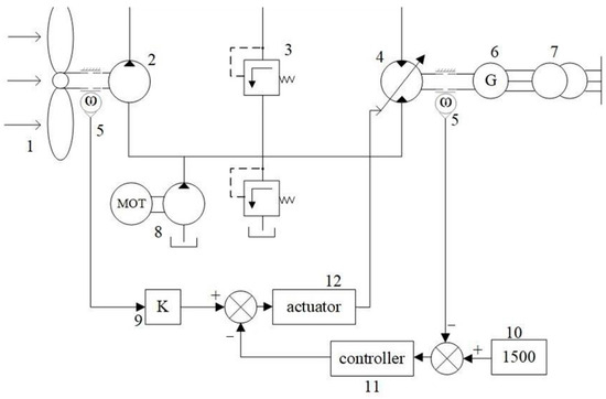
Figure 1.
The basic schematic diagram of the hydraulic wind turbine: 1—wind turbine; 2—quantitative pump; 3—safety valve; 4—variable speed motor; 5—speed sensor; 6—excitation synchronous generator; 7—grid; 8—refill mechanism; 9—swash plate deflection angle reference factor; 10—ideal speed value; 11—controller; 12—actuator.
According to the grid-connected conditions of hydraulic wind turbines, it is known that the speed range of the variable motor should be 1500 ± 6 r/min [28]. In this research, the adopted grid-connected speed-control approach is the indirect speed closed-loop control of variable motors. The speed of the quantitative pump is measured by the speed sensor, and the reference value of the deflection angle of the variable motor is calculated, so that the speed of the variable motor reaches about 1500 r/min [29]. Then, the variable motor deflection angle compensation controller is introduced to complete the small range of speed adjustment and realize the precise control of variable motor speed.
3. Mathematical Modeling
3.1. Mathematical Modeling of Quantitative Pump
Quantitative pump flow equation:
where Qp is the discharge flow of quantitative pump, Dp is the displacement of quantitative pump, ωp is the rotational speed of quantitative pump, Ctp is the leakage factor of quantitative pump, and ph is high pressure.
Quantitative pump moment balance equation:
where Tt is output torque of wind turbines, Tp is the load torque of quantitative pump, Jp is used to represent the quantification of the moment of inertia of the pump shaft, and Bp is the damping factor of quantitative pump.
3.2. Mathematical Modeling of Variable Motor
Variable motor flow equation:
where Qm is the discharge flow of variable motor; Dm is the displacement of variable motor; ωm is the rotational speed of variable motor; Ctm is the leakage factor of variable motor; Km is the displacement gradient of variable motor; and γ is the deflection angle position of variable motor, γ ∈ [0,1].
Variable motor moment balance equation:
where Tm is the drive torque of variable motor, Te is the load torque of variable motor, Jm is the moment of inertia on the variable motor shaft, and Bm is the damping factor of variable motor.
3.3. Mathematical Modeling of Hydraulic Piping
High-pressure line flow equations:
where V0 is total volume of high-pressure chamber, and βe is volumetric modulus of elasticity of oil.
3.4. Mathematical Modeling of the Variable Motor Deflection Angle Control System
The variable motor deflection control system consists of an electro-hydraulic servo valve and hydraulic cylinder. First, the current control signal of the electro-hydraulic servo valve is given to change the direction of the valve. Then, the flow of hydraulic fluid into the hydraulic cylinder changes, pushing the piston rod of the hydraulic cylinder to displace it. Finally, the displacement of the piston rod drives the variable motor oscillation angle to change the size of the displacement, thus realizing the motor-speed control. The control schematic is presented in Figure 2.
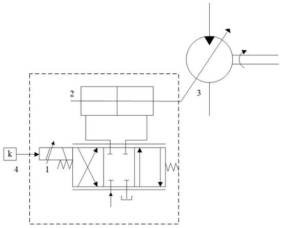
Figure 2.
Control system schematic: 1—electro-hydraulic servo valve; 2—hydraulic cylinder; 3—variable motor; 4—input signal.
Model the electro-hydraulic servo valve as a proportional element:
where i is the current, Kp is the servo amplifier gain, u is the output voltage, XV is the displacement of the valve core, and KSV is the gain.
Electro-hydraulic servo valve flow equation:
where QL is the servo valve flow, Kc is the servo valve pressure gain, and pL is the load pressure.
Combining Equations (6)–(8) yields the following:
Perform the Laplace transformation on Equation (9):
Hydraulic cylinder flow equation:
where Ap is the piston effective area, Xp is the piston displacement, Ctp is the total leakage factor, and Vl is the total compression volume.
Perform the Laplace transformation on Equation (11):
Hydraulic cylinder force balance equation:
where mi is the total mass of the piston, Bp is the viscous damping factor, K is the load spring stiffness, and FL is the piston load force.
Perform the Laplace transformation on Equation (13):
Combining Equations (10), (12), and (14) yields the following:
where Kce is the total flow pressure factor, .
3.5. Mathematical Modeling of Synchronous Generator
In hydraulic wind turbine systems, the integration of the variable-displacement motor and the excitation synchronous generator plays a critical role in energy conversion. The rotational shaft of the variable-displacement motor is coupled directly or via a linkage to the rotor shaft of the excitation synchronous generator, ensuring synchronous rotation between the two components. This synchronous rotation is critical for efficient energy transfer. When driven by hydraulic fluid, the variable-displacement motor transfers its rotational speed and torque directly to the rotor of the excitation synchronous generator. The rotor’s rotation induces a magnetic field via the excitation winding, generating an alternating voltage in the stator. This process enables the sequential conversion of energy from hydraulic to mechanical and finally to electrical forms. The working principle of the excitation synchronous generator is illustrated in Figure 3b.
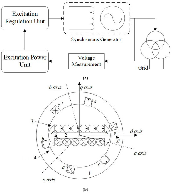
Figure 3.
The working principle of the excitation synchronous generator. (a) The control schematic diagram of the excitation synchronous generator. (b) The schematic diagram of synchronous generator structure: 1—stator; 2—rotor; 3—air gap; 4—armature winding.
The coaxial connection design enhances energy transfer efficiency between the variable-displacement motor and the excitation synchronous generator, significantly reducing energy losses, such as mechanical friction and magnetic hysteresis. This reduction in energy losses further enhances the system’s overall efficiency. Moreover, the precise synchronization of rotational speeds ensures that the output frequency of the excitation synchronous generator matches the grid frequency, thereby ensuring stable and reliable grid integration. The electrical energy is then conditioned by transformers and power electronics for grid integration and end-use.
The voltage equation of a three-phase synchronous generator is as follows:
The flux linkage equation is as follows:
where u is voltage, i is current, ψ is flux linkage, r is resistance, L is self-inductance, M is mutual inductance, a is a-axis, b is b-axis, c is c-axis, f is field winding, D is longitudinal damping factor, and Q is transverse damping factor.
To perform the Park reduction-order transformation on Equations (16) and (17), transforming the three-phase a, b, and c coordinate system into the d, q and 0 coordinate system, the transformation formula is as follows:
where θ is the angle between the d-axis and the a-axis.
After the transformation, the voltage equation of the synchronous generator is as follows:
The flux linkage equation is as follows:
where X is reactance, d is d-axis, q is q-axis, and 0 is 0-axis.
4. Controller Design
The open-loop transfer function of the valve-controlled hydraulic cylinder system is derived from Equation (15). This transfer function is a nonlinear function. Based on the literature [5], the Bode diagram of the variable motor speed-control system is analyzed. The Bode diagram of the system is illustrated in Figure 4, and the corresponding parameter values are provided in Table 1.
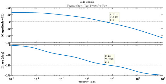
Figure 4.
Bode diagram of the open-loop system.

Table 1.
System parameters.
By analyzing Figure 4, the amplitude margin of the open-loop system is found to be +7.76 dB, and the phase margin is +6.07 deg. Theoretically, the system is stable. However, the extremely small phase margin indicates a very low damping ratio, leading to significant overshoot and prolonged settling time. Additionally, the system exhibits poor robustness against parameter variations and external disturbances. Therefore, it is necessary to implement a controller for correction.
Traditional PID control is simple to operate and easy to adjust. However, due to the strong nonlinearity of the speed-control system in hydraulic wind turbine generator sets, fixed PID parameter values cannot simultaneously satisfy both the dynamic and static performance requirements of the system. Therefore, this paper proposes the use of a fuzzy PID controller, which combines the high adaptability of the fuzzy control algorithm with the high precision of the PID controller to effectively manage the nonlinear system. The principle of fuzzy PID control is illustrated in the figure. In this study, a two-input and three-output fuzzy controller is employed, where the inputs are the deviation, e, and the deviation change rate, ec, and the outputs are the parameter adjustment values, dKp, dKi, and dKd. The fuzzy universes of discourse for these five variables are confined to the range of [−1,1] and divided into seven fuzzy subsets: {Negative Big, Negative Medium, Negative Small, Zero, Positive Small, Positive Medium, Positive Big}, abbreviated as {NB, NM, NS, ZO, PS, PM, PB}. The fuzzy rule tables for dKp, dKi, and dKd are presented in Table 2 [30]. The corresponding three-dimensional response surfaces are depicted in the Figure 5.
Table 2.
Fuzzy rules for dKp, dKi, and dKd.
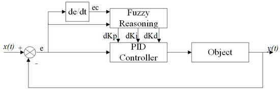
Figure 5.
Schematic diagram of fuzzy PID control.
In hydraulic systems, mechanical stress on components like pumps, motors, and pipes is a major concern, while the time constant plays a crucial role in determining system responsiveness. Traditional fuzzy PID controllers, once designed, employ fixed fuzzy rules, defuzzification methods, and static quantization and proportional factors, which restrict their adaptability. Such limitations can lead to significant operational issues. For example, in hydraulic actuators, the inability of the controller to adjust to varying loads may prolong the time required to reach the target position (linked to the time constant), resulting in inefficient performance. Additionally, during sudden load changes, a fixed-parameter fuzzy PID controller often fails to provide an adequate response. Inadequate flow rate regulation under such conditions can cause a sharp pressure increase in the hydraulic motor, leading to elevated mechanical stress on system components. These issues highlight the constraints imposed by fixed proportional and quantization factors, which hinder the controller’s effectiveness in managing the complex and variable demands of hydraulic systems.
Consequently, fixed factor parameters will render the controller incapable of adapting to complex and variable real-world operating conditions, significantly limiting its versatility and adaptability. To ensure that the control performance consistently maintains excellent robustness, as well as dynamic and static performance, an intelligent optimization algorithm is employed to dynamically adjust the quantization factors, Ke and Kec; and the proportional factors, Kup, Kui, and Kud, of the fuzzy controller in real time.
PSO is an algorithm that iterates the individual positions of a group of particles to finally obtain the best solution [31,32,33]. However, when addressing complex high-dimensional optimization problems, the issue of PSO being prone to falling into local optima becomes particularly prominent. During the later stages of the search process, the diversity of the particle swarm diminishes rapidly, leading to premature convergence and preventing the algorithm from locating the global optimal solution [34,35]. Additionally, the selection of PSO-related parameters heavily relies on extensive experimentation and empirical knowledge. Inappropriate parameter choices may result in either excessively slow convergence or a complete failure to converge [36,37].
Therefore, this paper introduces an enhanced Circle chaotic mapping into the PSO, which utilizes the high complexity and randomness of the chaotic particle swarm to enhance the global search capability of the particle swarm algorithm, avoid the problems of premature convergence and falling into the local optimal solution of the algorithm, and enhance the optimization accuracy of the algorithm [38]. To enhance the equilibrium between the algorithm’s global exploration and local exploitation, a formula for inertia weight that decreases linearly is incorporated.
Circle’s formula for chaotic mapping:
Linearly decreasing inertia weight formula:
where ωs is initial inertia weights, ωe is final inertia weights, d is current number of iterations, and K is total number of iterations.
The enhanced CPSO’s flowchart is presented in Figure 6. The principle of the enhanced CPSO fuzzy PID control is presented in Figure 7.
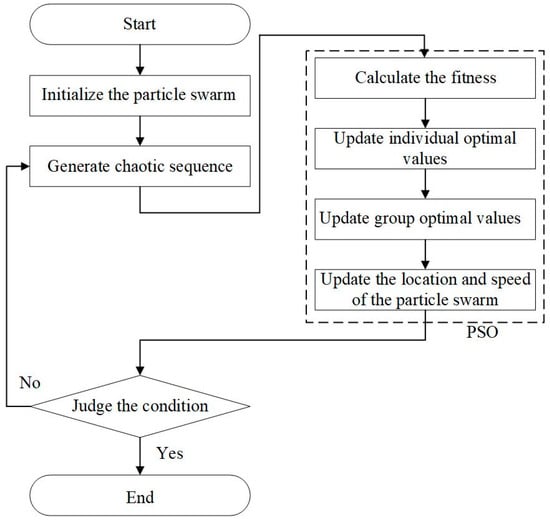
Figure 6.
Flowchart of the enhanced CPSO.
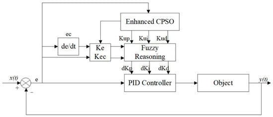
Figure 7.
The principle of the enhanced CPSO fuzzy PID control.
5. System Simulation and Analysis
5.1. Simulation Principle
A 30 kW hydraulic wind turbine is used as a basis to investigate the factors affecting the stable output of variable motor speed. The simulation is conducted through the joint of AMESim and MATLAB/Simulink. The speed-control system of the quantitative pump-variable motor is modeled in AMESim, and the enhanced CPSO fuzzy PID control model in MATLAB/Simulink. A generator is utilized in the simulation to create a model for the wind turbine’s speed input. The schematic diagram of control system is presented in Figure 8. The detailed models of the control system are presented in Figure 9. The parameters of the primary components are presented in Table 3.
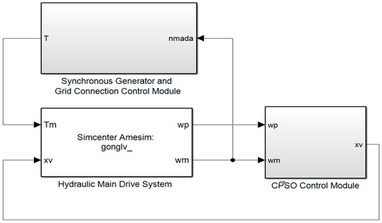
Figure 8.
Schematic diagram of the control system.
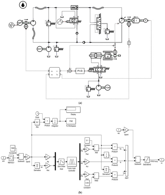
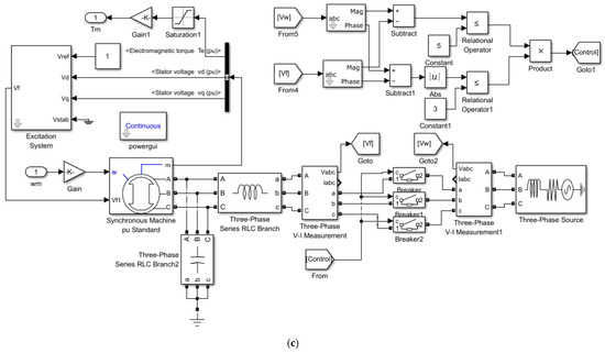
Figure 9.
Detailed model of the control system. (a) Hydraulic main drive system. (b) CPSO control module. (c) Synchronous generator and grid-connection control module.
Table 3.
Primary components’ parameters.
5.2. Simulation Results and Analysis
Based on indirect speed control of the variable motor, the effects of different variable motor swashplate deflection angle conversion factors and different quantitative pump-speed inputs on the constant speed output of variable motor are investigated separately.
- (1)
- The effects of different variable motor swashplate deflection angle conversion factors
For simulation, a constant speed input of 400 r/min is given to the quantitative pump, and other parameters are kept constant. The pendulum angle conversion factors are 0.001, 0.00105, and 0.0011, respectively. The speed response of variable motor is investigated by fuzzy PID, PSO fuzzy PID, and enhanced CPSO fuzzy PID control approaches. The response curves are presented in Figure 10a, Figure 11a, and Figure 12a. The corresponding deflection angle variations are presented in Figure 10b, Figure 11b, and Figure 12b.
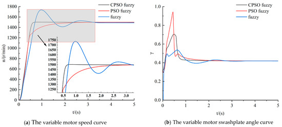
Figure 10.
Deflection angle conversion factor 0.001.
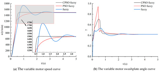
Figure 11.
Deflection angle conversion factor 0.00105.
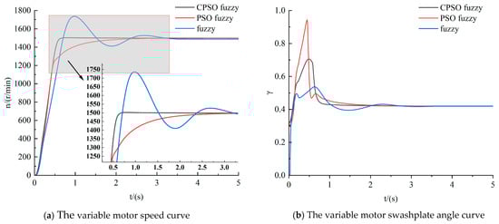
Figure 12.
Deflection angle conversion factor 0.0011.
As can be seen from Figure 10, Figure 11 and Figure 12, when the variable motor deflection angle conversion factor varies in a small range from 0.001 to 0.0011, the variable motor output speed curves are basically the same in the three control modes. And the final stabilization values can all reach 1500 r/min, which meets the variable motor-speed requirements. This factor has an insignificant impact on the speed of the variable motor.
The speed-response curves of the variable motor are analyzed for the three control approaches in Figure 10:
The ascension time, settling time, and overshoot for the three control approaches in Figure 10a are presented in Table 4. According to the calculations, the enhanced CPSO fuzzy PID control approach reduces the ascension time by 40% and 76%, and the settling time by 80% and 76%, compared to the fuzzy PID and PSO fuzzy PID control, respectively. At the same time, the system exhibits no overshoot from this control approach. In Figure 10b, the variable motor deflection angle by PSO fuzzy PID control varies the most at 0–2 s. Theoretically, it has the shortest ascension time, but because the hydraulic fluid transfer takes some time, the drastic change in the deflection angle currently affects the stability of the system. The enhanced CPSO fuzzy PID is fast and stable at the same time, so that the variable motor speed can be well controlled with this control approach.
Table 4.
Variable motor-speed response for three control modes.
- (2)
- The effects of different quantitative pump speed inputs
For simulation, the deflection angle conversion factor of 0.00105 is given, and other parameters are kept constant. The quantitative pump speeds are 400–500 r/min for step input, 500–600 r/min for step input, and 400–500 r/min for random input. The speed response of the variable motor is investigated for three control approaches. The response curves are presented in Figure 13a, Figure 14a, and Figure 15a, and the corresponding deflection angle variations are presented in Figure 13b, Figure 14b, and Figure 15b.
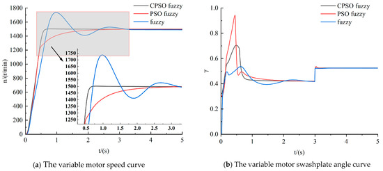
Figure 13.
Step input of 400–500 r/min.
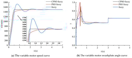
Figure 14.
Step input of 500–600 r/min.
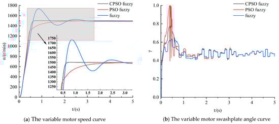
Figure 15.
Random input of 400–500 r/min.
Based on the response curves in Figure 13, Figure 14 and Figure 15, the following analysis is made of the variable motor-speed response for different quantitative pump-speed inputs in the three control modes:
The ascension time, settling time, and overshoot for the three control approaches in Figure 13a are presented in Table 5. According to the calculations, the enhanced CPSO fuzzy PID control approach reduces the ascension time by 40% and 76%, and the settling time by 80% and 76%, compared to the fuzzy PID and PSO fuzzy PID control, respectively. At the same time, the system exhibits no overshoot with the PSO fuzzy and enhanced CPSO fuzzy control approaches. In Figure 13b, the variable motor deflection angle in PSO fuzzy PID control varies the most at 0–2 s. When the rotational speed of the quantitative pump steps up to 500 r/min at 3 s, the deflection angle of the variable motor increases with it, and the rotational speed does not change significantly. Combining the analysis in Figure 10b with the data from the three control approaches in this case, the enhanced CPSO fuzzy PID control proves to be the best.
Table 5.
Step input of 400–500 r/min.
The ascension time, settling time, and overshoot for the three control approaches in Figure 14a are presented in Table 6. According to the calculations, the enhanced CPSO fuzzy PID control approach reduces the ascension time by 25% and 72%, and the settling time by 80% and 72%, compared to the fuzzy PID and PSO fuzzy PID control, respectively. At the same time, the system exhibits no overshoot with the PSO fuzzy and enhanced CPSO fuzzy control approaches. In Figure 14b, the variable motor deflection angle in PSO fuzzy PID control varies the most at 0–2 s. When the rotational speed of the quantitative pump steps up to 600 r/min at 3 s, the deflection angle of the variable motor increases with it, and the rotational speed does not change significantly. Combining the analysis in Figure 10b with the data from the three control approaches in this case, the enhanced CPSO fuzzy PID control proves to be the best.
Table 6.
Step input of 500–600 r/min.
The ascension time, settling time, and overshoot for the three control approaches in Figure 15a are presented in Table 7. According to the calculations, the enhanced CPSO fuzzy PID control approach reduces the ascension time by 37.5% and 80%, and the settling time by 83% and 80%, compared to the fuzzy PID and PSO fuzzy PID control, respectively. At the same time, the system exhibits no overshoot with the PSO fuzzy and enhanced CPSO fuzzy control approaches. In Figure 15b, when the input quantitative pump speed is a random value of 400–500 r/min, the variable motor deflection angle magnitude varies with the quantitative pump speed, and the rotational speed does not change significantly. Combining the analysis in Figure 10b with the data from the three control approaches in this case, the enhanced CPSO fuzzy PID control proves to be the best.
Table 7.
Random input of 400–500 r/min.
In summary, when the variable motor swashplate deflection angle factor varies in a small range from 0.001 to 0.0011, the variable motor-speed input is only affected by the quantitative pump speed input, rather than the variation in the swashplate deflection angle factor. When different quantitative pump speeds are entered, the speed of the variable motor can eventually be maintained at about 1500 r/min. This is because there is a positive relationship between the base value of the variable motor deflection angle and the speed of the quantitative pump. When the swashplate deflection angle is compensated for in a small range, this relationship remains essentially unchanged. Meanwhile, the enhanced CPSO fuzzy PID control approach significantly reduces the overshooting amount, settling time, and ascension time in the speed-control system, which is contrasted with the other two control approaches. The enhanced approach enhances the stability and rapidity of the system, and it greatly meets the control requirements of the system.
6. Conclusions
In this study, based on the grid-connected speed-control requirements of a hydraulic-type wind turbine, the following results were obtained for the speed control of a quantitative pump-variable motor system:
- (1)
- In this study, the indirect speed closed-loop control approach of a variable motor is adopted. The constant speed output of the variable motor is realized by compensating the swashplate deflection angle of the variable motor in a small range.
- (2)
- An enhanced CPSO fuzzy PID is suggested to significantly reduce the overshoot, settling time, and ascension time of the system. This approach enhances the stability and rapidity of the system, satisfies the requirement for grid connection, and offers robust assistance in the performance improvement of the hydraulic system.
- (3)
- When the variable motor swashplate deflection angle factor and quantitative pump speed fluctuate within a specific range, there is no impact on the rotational speed of the variable motor.
Author Contributions
Conceptualization, Y.W. and Y.C.; methodology, Y.W.; software, Y.C.; validation, Y.W.; formal analysis, Y.W.; investigation, Y.Y., W.Z., S.C. and Y.W.; resources, Y.C. and G.W.; data curation, Y.W.; writing—original draft preparation, Y.W.; writing—review and editing, Y.C.; visualization, Z.Q., J.X., X.K. and Y.Z.; supervision, Y.C.; project administration, Y.C. and G.W.; funding acquisition, Y.C. All authors have read and agreed to the published version of the manuscript.
Funding
This research was funded by National Natural Science Foundation of China (grant number 51376096), “Fourteenth Five-Year Plan” Provincial Key Construction Discipline Project of Jiangsu Province (2022-0802 Mechanical engineering), and Jiangsu Engineering Research Center for Wind Energy Application.
Data Availability Statement
Some or all data, models, or codes that support the findings of this study are available from the corresponding author upon reasonable request.
Conflicts of Interest
The authors declare that they have no conflicts of interest.
References
- Akhmatov, V. Analysis of Dynamic Behavior of Electric Power Systems with Large Amount of Wind Power; Technical University of Denmark: Copenhagen, Denmark, 2003; pp. 9–11. [Google Scholar]
- Polinder, H.; van der Pijl, F.F.A.; de Vilder, G.J.; Tavner, P.J. Comparison of direct-drive and geared generator concepts for wind turbines. IEEE Trans. Energy Convers. 2006, 21, 725–733. [Google Scholar]
- Qin, Y.L. Technology Development and Prospect of Wind Turbine Generators. Power Energy 2011, 32, 325–334. [Google Scholar]
- Kong, X.D.; Song, Y.; Ai, C. Research on Constant Speed Control Approach of Variable Speed Input Quantitative Pump-Constant Speed Output Variable Motor System. Chin. J. Mech. Eng. 2016, 52, 179–190. [Google Scholar]
- Wu, J.Z.; Zhao, Y. Research of Speed Control for Synchronization of Hydraulic Wind Turbine. Fluid Transm. Control. 2013, 01, 7–10. [Google Scholar]
- Jiang, Z.Y.; Yang, L.M.; Gao, Z.; Moan, T. Integrated dynamic analysis of a spar floating wind turbine with a hydraulic drivetrain. Renew. Energy 2022, 201, 608–623. [Google Scholar]
- Zhang, L.Q.; Zhang, J.F.; Zheng, W.J.; Lian, M. Research on Constant Speed Control of Hydraulic Wind Turbine. Chin. Hydraul. Pneum. 2015, 05, 127–129. [Google Scholar]
- Do, H.T.; Dang, T.D.; Truong, H.; Ahn, K.K. Maximum Power Point Tracking and Output Power Control on Pressure Coupling Wind Energy Conversion System. IEEE Trans. Ind. Electron. 2018, 65, 1316–1324. [Google Scholar]
- Wei, L.J.; Liu, Z.G.; Zhao, Y.Y.; Wang, G.; Tao, Y. Modeling and control of a 600 kW closed hydraulic wind turbine with an energy storage system. Appl. Sci. 2018, 8, 1314. [Google Scholar] [CrossRef]
- Liu, Z.G.; Yang, G.L.; Wei, L.J.; Yue, D. Variable speed and constant frequency control of hydraulic wind turbine with energy storage system. Adv. Mech. Eng. 2017, 9, 168781201771519. [Google Scholar]
- Liu, Z.G.; Yang, G.L.; Wei, L.J.; Yue, D.; Tao, Y. Research on the robustness of the constant speed control of hydraulic energy storage generation. Energies 2018, 11, 1310. [Google Scholar] [CrossRef]
- Yang, G.S.; Chen, L.J.; Cai, P.Y.; Gao, W.; Ai, C. Adaptive Disturbance Rejection and Power Smoothing Control for Offshore Hydraulic Wind Turbines Based on Pitch and Motor Tilt Angles. Energies 2024, 17, 6244. [Google Scholar] [CrossRef]
- Chen, L.J.; Li, J.B.; Zhang, L.; Gao, W.; Ai, C.; Ding, B.C. A novel collaborative control algorithm for maximum power point tracking of wind energy hydraulic conversion system. Wind Energy 2023, 26, 1299–1317. [Google Scholar]
- Liu, K.Y.; Chen, W.; Chen, G.X.; Dai, D.D.; Ai, C.; Zhang, X.; Wang, X. Application and analysis of hydraulic wind power generation technology. Energy Strategy Rev. 2023, 48, 101117. [Google Scholar]
- Ai, C.; Zhang, Y.B.; Jia, C.; Zhang, L.; Kong, X.D. Research on rotating speed control of the vertical axis hydraulic wind turbine. Trans. Can. Soc. Mech. Eng. 2019, 44, 567–579. [Google Scholar]
- Ai, C.; Gao, W.; Chen, L.; Guo, J.; Kong, X.; Plummer, A. Bivariate grid-connection speed control of hydraulic wind turbines. J. Frankl. Inst. 2021, 358, 296–320. [Google Scholar]
- Wu, K.; Chen, P.W. Research on Speed Control of Quantitative Pump-Variable Motor System Based on AMESim and Simulink Co-simulation. J. Value Eng. 2024, 43, 136–139. [Google Scholar]
- Dessale, A.W.; Ayodeji, O.S.; Girma, K.A. Particle Swarm Optimization Algorithm Based Fuzzy PID Controller Design for Speed Tracking Control of Separately Excited DC Motor. Adv. Control. Appl. Eng. Ind. Syst. 2024, 6, 237. [Google Scholar]
- Li, T.H.; Li, J.; Jiang, J.B.; Liu, X.Y. Fuzzy PID control based on genetic algorithm optimization inverted pendulum system. J. Phys. Conf. Ser. 2024, 2816, 012001. [Google Scholar]
- Zhou, H.; Wu, J.; Zheng, X.; Zhu, H. Fuzzy PID controller based on enhanced LFPSO for temperature and humidity control in a CA ripening system. J. Food Process Eng. 2024, 47, e14651. [Google Scholar] [CrossRef]
- Cao, W.; Liu, Z.; Song, H.; Li, G.; Quan, B. Dung Beetle Optimized Fuzzy PID Algorithm Applied in Four-Bar Target Temperature Control System. Appl. Sci. 2024, 14, 4168. [Google Scholar] [CrossRef]
- Tang, H.; Ma, R.; Chen, Y.; Huang, L.; Jiao, R. Temperature Regulation of Hot Vapor Preservation Treatment of Litchi Based on PSO-Fuzzy PID. Appl. Sci. 2023, 13, 6888. [Google Scholar] [CrossRef]
- Kasruddin Nasir, A.N.; Ahmad, M.A.; Tokhi, M.O. Hybrid spiral-bacterial foraging algorithm for a fuzzy control design of a flexible manipulator. J. Low Freq. Noise Vib. Act. Control. 2022, 41, 340–358. [Google Scholar]
- Kumar, A.; Suhag, S. Whale Optimization Algorithm Optimized Fuzzy-PID Plus PID Hybrid Controller for Frequency Regulation in Hybrid Power System. J. Inst. Eng. India Ser. B 2022, 103, 633–648. [Google Scholar]
- Sun, Z.; Cao, Y.; Wen, Z.; Song, Y.; Sun, Z. A Grey Wolf Optimizer algorithm based fuzzy logic power system stabilizer for single machine infinite bus system. Energy Rep. 2023, 9, 847–853. [Google Scholar]
- Yang, H.Y.; Hu, G.J. Comparative study on PID Control and Fuzzy Control of motor speed of hydraulic transmission type wind turbine. In Proceedings of the 2016 IEEE International Conference on Power and Renewable Energy (ICPRE), Shanghai, China, 21–23 October 2016; pp. 399–403. [Google Scholar]
- Ai, C.; Zhou, G.L.; Gao, W. Research on quasi-synchronous grid-connected control of hydraulic wind turbine. IEEE Access 2020, 8, 126092–126108. [Google Scholar]
- He, C.B.; Wang, J.C.; Song, L.; Ma, L. Summary of New Type Hydraulic Drive Wind Turbine. Noise Vib. Control. 2018, 38, 130–133. [Google Scholar]
- Ai, C.; Gao, W.; Chen, L.J.; Zhang, Y.B.; Guo, J.W. Research on Grid-connected Speed Control of Hydraulic Wind Turbine Based on Wind Speed Prediction. Chin. J. Mech. Eng. 2020, 56, 162–171. [Google Scholar]
- Wang, H.; Xie, H.; Shi, L.; Ma, L.; Bai, Y. Applications of Fuzzy-PID to the firing process control system of high-temperature shuttle kiln for zirconia-alumina products. In Proceeding of the 11th World Congress on Intelligent Control and Automation, Shenyang, China, 29 June–4 July 2014; pp. 4441–4446. [Google Scholar]
- Ke, X.F.; Xiao, S.D. Fuzzy PID Valve-controlled Hydraulic Cylinder Control Simulation Based on Particle Swarm Optimization. Hydraul. Pneum. Seals 2024, 44, 61–66. [Google Scholar]
- Zhu, Y.; Cao, K.; Ding, C.L.; Zhao, Y.; Gao, Q.; Wang, J.T. Fuzzy PID Control of Rotary Punch Drilling System Based on Particle Swarm Optimization. Hydraul. Pneum. 2024, 48, 53–63. [Google Scholar]
- Li, H.; Hu, X.B.; Zhang, X.J.; Wei, S.; Luo, Q. Kinematic parameters calibration of industrial robot based on RWS-PSO algorithm. Proc. Inst. Mech. Eng. Part C-J. Mech. Eng. Sci. 2023, 237, 3210–3220. [Google Scholar]
- Qin, Z.X.; Pan, D.Z. Enhanced Dual-Center Particle Swarm Optimization Algorithm. Mathematics 2024, 12, 1698. [Google Scholar] [CrossRef]
- Kun, M.; Qian, F.; Wei, K. Particle Swarm Optimization Combined with Inertia-Free Velocity and Direction Search. Electronics 2021, 10, 597. [Google Scholar] [CrossRef]
- Shami, T.M.; El-Saleh, A.A.; Alswaitti, M.; Al-Tashi, Q.; Summakieh, M.A.; Mirjalili, S. Particle Swarm Optimization: A Comprehensive Survey. IEEE Access 2022, 10, 10031–10061. [Google Scholar] [CrossRef]
- Bhargav, A.; Amitkumar, V.J.; Deepak, K.G.; Nicu, B.; Phatiphat, T. PSOa: A Fragmented Swarm Optimization for Enhanced Load Frequency Control of a Hybrid Power System Using FOPID. Energies 2023, 16, 2226. [Google Scholar]
- Song, L.Q.; Chen, W.T.; Chen, W.H.; Lin, Y.; Sun, X.T. Enhancement and application of hybrid strategy-based sparrow search algorithm. J. Beijing Univ. Aeronaut. Astronaut. 2023, 49, 2187–2199. [Google Scholar]
Disclaimer/Publisher’s Note: The statements, opinions and data contained in all publications are solely those of the individual author(s) and contributor(s) and not of MDPI and/or the editor(s). MDPI and/or the editor(s) disclaim responsibility for any injury to people or property resulting from any ideas, methods, instructions or products referred to in the content. |
© 2025 by the authors. Licensee MDPI, Basel, Switzerland. This article is an open access article distributed under the terms and conditions of the Creative Commons Attribution (CC BY) license (https://creativecommons.org/licenses/by/4.0/).