Abstract
Parking path optimization is the principal problem of automatic vertical parking (AVP); however, it is difficult to determine a collision avoiding, smooth, and accurate optimized parking path using traditional parking reference trajectory optimization methods. In order to implement high-performance automatic parking reference trajectory optimization, we establish an automatic parking reference trajectory optimization model using cubic spline interpolation, and we propose an improved immune shark smell optimization (IISSO) to solve it. Firstly, we take the length of the parking reference trajectory as the optimization objective, and we introduce an intelligent automatic parking path optimization model using cubic spline interpolation. Secondly, the improved immune shark optimization algorithm combines the immune, refraction, and Gaussian variation mechanisms, thus effectively improving its global optimization ability. The simulation results for the parking path optimization experiments indicate that the proposed IISSO has a higher optimization accuracy and faster calculation speed; hence, it can obtain a parking path with higher optimization performance.
1. Introduction
AVP performance is a significant performance evaluation index used to determine the safety and comprehensive quality of intelligent vehicles. It is divided into two parts: the optimization of the parking reference trajectory and tracking control [1]. It is crucial to obtain a reference trajectory with collision avoidance and a smooth and short length, prerequisites for achieving high AVP performance [2]. Designing an AVP optimization algorithm with high performance is a research hotspot for scholars in the field of intelligent driving.
The successful implementation of AVP requires three steps: the first is to determine whether the parking feasibility constraint is established (available parking space detection); the second is to obtain an optimized reference trajectory for parking (parking trajectory optimization); and the third is to effectively track the path to the allowable parking range (parking trajectory tracking). In recent years, scholars have produced valuable research results on the problem of automatic parking. A parking space detection method suitable for underground and indoor parking environments was put forward in [3]. This method combined parking space marking and free space detection; however, a large number of vehicle sensors needed to be configured. A parking space detection method based on probabilistic occupancy filter was proposed, which overcame the defect of obstacle occlusion in the detection of traditional around view monitoring (AVM) sensors to a certain extent [4]. A swarm intelligence optimization framework combining gradient arithmetic and an adaptive parameter controller for multi-objective automatic parking operation planning was proposed in [5]. Based on driving experience and discrete kinematic differential equations, a parking trajectory optimization scheme suitable for a narrow environment was proposed in [6]. A parking trajectory tracking controller based on multi-constrained model predictive control (MMPC) was proposed in [7]. A three-layer framework was proposed to address the challenges of high nonholonomic constraints, unstable reverse dynamics, and non-convex obstacle avoidance constraints in parking tractor-trailer vehicles in extremely narrow environments [8]. Based on the switching control algorithm and backstepping theory, a control method for the fully automatic parking of vehicles was proposed in [9]. Improved A* and dynamic window approaches were proposed to enhance the accuracy and speed of tracked vehicle automatic parking [10]. Utilizing a recursive network structure, deep neural networks (DNNs) were used to approximate the optimal parking trajectory [11]. A novel adaptive pseudospectral (NAP) method was proposed to solve the time–energy optimal control model problem, minimizing the vehicle parking time and the energy output [12]. Restrictions on parking spaces can make parking more challenging. Algorithms for parallel parking and forward perpendicular parking path planning considering the parking corridor space were proposed in [13]. A geometric path plan consisting of two stages for the automatic execution of vertical and parallel parking in narrow spaces using reverse paths was proposed in [14]. In fact, in terms of emerging automatic parking technology, researchers pay attention to the detection and tracking control technology related to the success of parking. However, with the development of highway public transportation, people have more demanding requirements for parking quality such as collision avoidance, a smooth and short path, etc., and parking trajectory optimization technology has also attracted more attention as it matures.
In order to improve the area utilization rate, vertical parking spaces are used in parking lots and garages. Combining cubic spline interpolation and an intelligent optimization algorithm (IOA), it is easy to design an AVP trajectory optimization algorithm with high parking quality. For the AVP in a vertical parking space in a parking lot, an AVP trajectory immune moth flame optimization algorithm according to cubic spline was proposed in [15]. However, due to the lack of an effective method to deal with parking in a garage, the improved whale optimization algorithm lacks the ability to balance global exploration and local development, which limits its parking trajectory optimization performance.
Compared with the existing research on AVP reference trajectory optimization, the primary innovations of this article are as follows:
- A novel optimization model of a reference trajectory for AVP is constructed. In view of the problems with the existing AVP reference trajectory optimization, such as poor obstacle avoidance, low trajectory smoothness, a long path, and a large parking incline, a novel, reasonable, and feasible optimization model of the reference trajectory for automatic parking is established using cubic spline.
- A novel improved immune shark optimization algorithm is put forward to address the issue of local convergence in the existing shark optimization algorithm. This method organically incorporates refraction, Gaussian variation, and immunity mechanisms, which can effectively improve the global optimization performance and solve the problem of not being able to escape local convergence.
The content of the article is organized as follows: Section 1 comprises the introduction. Section 2 presents a new model of reference trajectory optimization for AVP based on cubic spline interpolation. Section 3 illustrates the proposed IISSO. Section 4 provides the AVP experimental verification. Section 5 concludes this work.
2. Model of Reference Trajectory Optimization and Related Principles for Automatic Vertical Parking
2.1. Basic Principles of Automatic Vertical Parking
Parking behavior that automatically parks a vehicle, moving from the starting zone to the allowable parking range of the vertical parking space, is called automatic vertical parking. The automatic vertical parking diagram is shown in Figure 1.
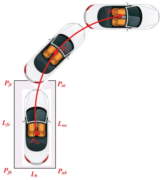
Figure 1.
Schematic diagram of AVP.
In Figure 1, are the central points of the vehicle body coverage areas collected by sensors. and are the near and far side lines of the parking garage, respectively. , , , and are the near corner point of the garage top, the distal corner point of the garage top, the near corner point of the garage bottom, and the far corner point of the garage bottom, respectively. After the vehicle reaches the parking area, if there are deviations in the parking attitude, the driver can adjust the parking within a buffer zone [16].
2.2. Feasibility Conditions for AVP
The AVP technology studied herein is focused on underground parking garages of high-end residential areas or large shopping malls, as well as the above-ground parking garages of large venues or squares. Generally, these parking lots have special administrators and cleaners, who can ensure a reduction in sudden obstacles when using AVP. Hence, in these high-end parking lots, sudden obstacles during AVP generally do not exist. Considering that in complex situations, especially sudden obstacles, the technology and experience of intelligent obstacle avoidance for unmanned real vehicle parking are not mature and that the research into intelligent obstacle avoidance technology for unmanned real vehicle parking has a high labor and monetary cost, obtains significantly smaller benefits, and is not popular in the marketplace, this research assumes the absence of obstacles in the parking environment. In addition, in this study, the parking garage is measurable; the bottom line and the side lines of the parking garage, as well as the bottom corner and the top corner of the parking garage, should be clearly identifiable. Further, the following feasibility constraints of starting to park in the garage must be met. First, the center point of the starting area should be in the feasible parking starting area ; that is, . Second, the connection line between the center point of the starting area and its bottom middle point is , the angle between and the garage bottom line is referred to as the starting inclination angle , and its absolute value must be less than the threshold value ; that is, .
If the AVP feasibility condition is not established, the AVP trajectory optimization and tracking control will not start. In addition, if a sudden obstacle is detected during AVP trajectory tracking control, the emergency braking command will be triggered to protect the safety of the person and vehicle.
2.3. Coordinate Transformation Principle for the Parking Plane
The standard coordinate system of a parking plane takes the far corner point of the garage bottom as the origin, and the garage bottom line as the positive side of the abscissa axis (x-axis). Using the standard coordinate system of a parking plane simplifies the parking calculation. In addition, real-time parking situations enable driver assessment, which enhances the rationality of parking decision making. Based on this, the principal devices of an intelligent automatic parking system, such as the parking feasibility decider, the reference trajectory optimizer, the parking controller, and the parking monitoring upper computer, are more suitable for use with the standard coordinate system of a parking plane. To convert the live-action coordinate system from the parking imaging system into the standard system of a parking plane, there are three steps: first, we cut the rectangular live-action parking scene with the maximum range; then, the coordinate system is rotated according to rotation angle of the live-action projection; finally, we translate the origin according to the coordinate of the far corner point at the bottom of the garage in the live-action coordinate system.
Suppose there exists a point s in the parking area, its coordinate is in the standard parking plane system, and the angle between it and the abscissa axis is ; obviously, .
Assuming the coordinate is given, the equation for converting it to the coordinate for the live-action parking plane system can be determined:
In the same way, assuming the coordinate point is given, the coordinate is also obtained easily. In the standard coordinate system for the parking plane, and are the horizontal and vertical coordinates of the central point of the feature region . Assuming that the starting inclination angle is small enough, in order to obtain the shortest possible parking reference trajectory, parking experiences show that the constraint of a decreasing abscissa and the ordinate of the central point of the feature regions must be met. The specific expression is
2.4. Reference Trajectory Optimization Model for AVP
The main purpose of this work is to study an effective and applicable optimization method for automatic vertical parking reference trajectory. Therefore, how to properly determine the control speed and the control attitude angle change rate, according to the specific characteristics of the vehicle itself and the tracking control algorithm, is not considered in this situation. In other words, we only need to provide the common vehicle kinematics equations, which are described as follows:
where denotes the parking process period, denotes the maximum threshold of the absolute value of the difference between the reference speed and the control speed , and denotes the maximum threshold of the absolute value of the difference between the reference attitude angle change rate and the control attitude angle change rate .
Obviously, due to the limited performance of the vehicle itself,
where and represent the maximum vehicle speed and maximum vehicle attitude angle change rate that can be achieved by vehicles of specific types, respectively.
The parking reference trajectory results from fitting the central points of all feature regions. The central point of the starting area is fixed, and the other feature regional center can be appropriately adjusted within a certain scope; they are the decision variables for parking reference trajectory optimization. Based on the reference trajectory optimization model for AVP, an IOA (intelligent optimization algorithm) can be used to obtain the AVP reference trajectory . In other words, the reference speed and reference attitude angle change rate at any time in the process can be obtained. Then, the appropriate tracking control algorithm can be adopted to obtain the corresponding tracking control trajectory. The specific automatic reversing parking reference trajectory optimization model is as follows:
where is the parking process period, is the area surrounded by both sidelines of the garage and the bottom line, is the set of sideline collision avoidance detection position points, is the position point for collision avoidance detection on the -th sideline, , and is the number of detection position points, obviously, . and are the interval distance for the parking and vehicle body coverage area under the -th period, respectively, is the parking time, is the number of periods, , , and ⌈⌉ is the upward rounding operator, because the vehicle cannot touch the bottom line of the garage and both sidelines, . and are the interval distance for parking and the difference of attitude angle under the -th period, respectively, and their thresholds are and , respectively; is the central point of the -th feature region, , and is its adjustable area, obviously, . In this work, the cubic spline fitting method is adopted, and is the fitted reference trajectory curve of the parking garage. is the line between the central point of the parking area and the bottom midpoint of the garage, is the parking inclination angle, which is the angle between and the far side line of the garage, and is the absolute value threshold. is the parking position error, is the threshold of its absolute value, and is the ordinate value of the expected parking point. is the reference trajectory for the parking garage, and its length reflects the performance quality of the parking optimization method to a considerable extent; hence, it is an important parking optimization objective.
The cubic spline fitting method uses the cubic spline interpolation function to fit the curve, which has been widely applied in many industries.
We assume that, given the interval and its interpolation points , the cubic spline interpolation function has the following two characteristics.
First, is a cubic polynomial within any subinterval , and the specific expression of the cubic polynomial can be given as
where represents the piecewise cubic polynomial function of cubic spline interpolation, denotes the interpolation point, while , , , and denote the polynomial coefficients of the piecewise function .
In addition, should be second-order continuously differentiable within the interval .
If the coordinates of the central points of all feature regions under the standard parking plane system are obtained, the smooth parking reference trajectory can be quickly obtained using the cubic spline fitting method. This is a significant advantage that the geometric fitting method does not have.
The line width of the garage sign line is usually between 0.1 and 0.15 m. Therefore, the maximum collision tolerance width should be set as 0.1 m. Assuming that the sideline collision avoidance detection points are evenly distributed, the distance of the collision avoidance detection points between adjacent sidelines is set to . Based on the geometry, the following constraints should be met:
where and are the length of the near and far side lines of the garage, respectively.
2.5. Solution Principle of the Parking Trajectory Length
The vehicle parking trajectory is obtained using cubic spline interpolation, in which case the function expression of the trajectory is difficult to obtain directly. To calculate the trajectory length of such a complex curve, we can solve it as follows.
Let the cubic spline curve be , where t is a parameter. We sample n points uniformly or non-uniformly on the curve to obtain a set of sampling points . For every sampling point , we find the two endpoints and of its corresponding curve segment and calculate the distance between these two points. The total length of the parking trajectory is the sum of the lengths of all the curve segments:
Specifically, it includes sampling, quantization, coding, and so on [17].
Through the reasonable sampling method, the accuracy and reliability of the parking trajectory length calculation can be ensured. The specific sampling method is as follows:
First, based on the obtained parking trajectory, an effective and feasible sampling principle is given to implement sampling.
Then, every sampling point is assigned a label to facilitate subsequent processing.
Next, we check whether the sampling points cover all the key areas of the curve and whether the requirements of the sampling interval are met.
Finally, the details of every sampling point, such as the coordinates, time stamps, feature value, etc., are recorded for subsequent processing.
The quantization process is the basis for calculating the length of the parking trajectory, and its accuracy directly affects the reliability of the final result. The specific quantification methods are as follows:
- Curve segment division: We divide the sampling points’ set into several curve segments. Every curve segment represents consecutive sampling points. The division of the curve segments should ensure that the length of every curve segment is roughly equal, to achieve equal-length quantization.
- Curve segment endpoints extraction: For every curve segment, we extract its two endpoints as the endpoints of the curve segment, and the coordinates of the two endpoints are calculated to determine the length of the curve segment.
- Curve segment length calculation: We calculate the distance between the two endpoints of every curve segment. In the two-dimensional plane coordinate system, the distance between the two endpoints is .
- Result verification: We verify the length of every curve segment to determine whether the length of the curve segment meets the expected error range.
- Quantization result recording: We record the length of every curve segment for the subsequent trajectory length calculation.
Through encoding, the original data can be converted into a form suitable for computer processing for subsequent calculation and analysis. The coding steps are as follows:
- Selection of the encoding method: We select the appropriate encoding method according to the data type to be encoded. For the decimal index value of the parking position reference point set, binary code can be used instead.
- Data conversion: We convert the original data to the encoding format. The index values of the parking position reference points’ set need to be converted into binary numbers.
- Encoding processing: The converted data are encoded according to a fixed length. We fill every binary number to the specified length to ensure that every coding length is the same.
- Verification of the encoding results: We verify whether every encoding length is the same and whether every coding can correctly represent the original data.
- Result recording: We record the encoding results and prepare them for subsequent intelligent algorithm optimization.
3. Improved Shark Optimization Algorithm
3.1. Shark Optimization Algorithm
The shark optimization algorithm is an intelligent optimization algorithm, proposed by Abedinia et al. in 2014, to simulate shark foraging behavior. It has good global convergence performance [18].
In the shark population, every shark at any location moves at a speed toward the location with the stronger odor, as follows:
where is the j-th dimensional speed for the i-th shark at the k-th iteration, , , , is the dimension of the decision variables, is the shark population scale, and is the maximum number of iterations.
When sharks swim, there is inertia, and their speed is bounded; so, the speed of every dimension is
where denotes the j-th dimensional location of the i-th shark at the k-th iteration; denotes the objective function; denotes the gradient coefficient; denotes the weight coefficient; and are random numbers in the iterative calculation process; denotes the speed limit rate of the k-th generation.
The shark updates its location through forward movement. The location of the forward movement is updated as follows:
where is the original location of the i-th shark of the k-th generation, and represents the time interval of the -th generation.
In addition to forward movement, sharks also make rotational movements within a small range along the search path. The location of the rotational motion is updated as
where m denotes the number of local searches for individual sharks, , M denotes the number of rotational movements, and denotes the random number in the iterative calculation process.
If the shark finds a stronger smell location in its rotary motion, it will continue the search toward that location. The formula for updating the location of the continued search is
The shark updates its location by moving forward and rotating to obtain the best possible solution [19].
3.2. Refraction Mechanism
Opposition Based Learning (OBL) was proposed by Tizhoosh in 2005 [20]. By introducing reverse solutions, the search scope of the algorithm can be expanded, thereby improving its global optimization ability. The introduction of a reverse learning strategy in the early stage of algorithm iteration can achieve a significant improvement. With the increase in the number of iterations, the reverse solution will fall into a local optimal phenomenon. To effectively improve the global optimization performance of the shark optimization algorithm, the refractive optimization mechanism, based on the refraction principle, is combined into the shark optimization algorithm, and it is renamed the improved shark smell algorithm (ISSO). The refraction principle diagram is expressed in Figure 2.
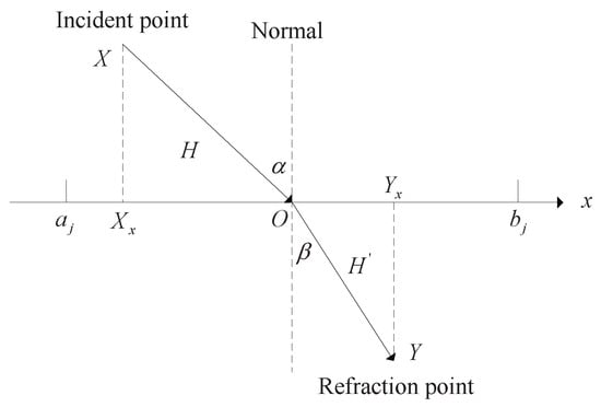
Figure 2.
The diagram of the refraction principle.
As can be seen from Figure 2, in the j-th dimension of the solution space (the value is between and ), the x-axis is used as the dividing line. The part above the x-axis is considered the vacuum of nature, and the part below the x-axis is considered other media. Above the x-axis there is a light point X, namely the incident point. An incident light is emitted from the incident point onto the intersection O with the x-axis, where the incident light length is labeled as H. The incident light will undergo refraction at the point of intersection O, resulting in refracted light with Y as the refraction point, and the refracted light length is labeled as . Thus, the formula for calculating the sine value of the incident angle and the refraction angle can be given as
Further, the formula for calculating the refractive index can be can be derived as
We make , and after the equivalent replacement in the equation, we obtain
where and are the x-axis components of the refraction point and the incident point, respectively.
The refraction point location can be changed through tuning f and refractive index . When the current solution is trapped in the local optimum, the algorithm makes the current solution escape through the refraction optimization mechanism. The refraction optimization mechanism is as follows: after reverse learning, the inverse solution will be obtained; if the inverse solution is still far away from the optimum solution, the location of the candidate solution needs to be changed by repeated refraction operations until it is out of the local optimal solution. A schematic diagram of the specific position relationship between the refractive solution and the current solution in two-dimensional space is expressed in Figure 3.
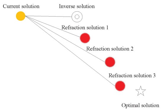
Figure 3.
Schematic diagram of the position relationship between the refraction solution and the current solution in two-dimensional space.
3.3. Gaussian Variation Mechanism
Gaussian perturbation is a kind of perturbation intensity that conforms to a Gaussian distribution (normal distribution). The mechanism to achieve variation using Gaussian perturbation is referred to as the Gaussian variation mechanism. In this work, a shark optimization algorithm with Gaussian variation is adopted to update the optimal location. For the optimal shark location with index i, the specific optimal shark location with a Gaussian variation is
where and are the original values of the k-th dimension for the optimal shark location with index i and its updated value after Gaussian variation; is the k-th dimension of the weight vector that corresponds to the perturbation properties of the entire shark population, ; is a random number that corresponds to the Gaussian distribution (normal distribution) with a mean value of and a standard deviation of .
Through the feature properties of Gaussian distribution, Gaussian variation can realize the key search of the local region near the original individual [21]. So, the introduction of a Gaussian variation mechanism plays two important roles:
- It can effectively expand and strengthen the local search scope and intensity of the shark optimization algorithm, which is conducive to improving its local search ability.
- If the shark optimization algorithm is trapped, risking local convergence, the powerful local perturbation in the region will significantly help it to escape.
3.4. Immune Mechanism
Based on the immune principle and the mechanism of the human immune system, various artificial immune algorithms have been proposed. The immune mechanism principle is to take the antigen as the global optimum solution to be sought by the shark population and the antibody as an individual in the shark population. When the antigen is stimulated by an external invasion, new antibodies are continuously produced, to achieve immune effects. However, if they not controlled, the immune cells with higher concentrations will monopolize the entire population. Therefore, the artificial immune algorithm relies on a concentration selection mechanism to maintain population diversity, thereby avoiding the local convergence of the algorithm and enhancing its global search ability. The concentration choosing mechanism of the artificial immune algorithm is introduced into the shark optimization algorithm to improve its optimization efficiency. In the mechanism of concentration choosing, the antibody concentration and its concentration probability are calculated according to the following formulas:
where , , and represent the fitness function value, the antibody concentration, and the concentration probability of the i-th individual, respectively, and .
In the selection mechanism based on antibody concentration, the immune system will promote the production of antibodies that have greater lethality against antigens, and it will suppress antibodies that are less lethal and in higher concentrations. The adoption of the selection mechanism based on antibody concentration in the shark optimization algorithm can adjust the distribution of individual sharks in space, improving possibility of escaping from the local optimum and seeking the global optimum, thus significantly promoting the optimization ability of the algorithm.
4. Experimental Verification
4.1. Description of the AVP Experiment Scenes
The experimental vehicles in this work were equipped with four ranging radars on the rear bumper, four on the side of the front and rear bumpers, and four on the front bumper, for a total of twelve ranging radars. During the AVP process, these 12 ranging radars can realize the close-range blind area monitoring function, which can be used to detect the front and rear obstacles and identify the position of each side line and corner point of the garage. AVM (Around View Monitor) is an important subsystem of the image transmission and processing system. It collects the data from the surrounding environment through four image sensor cameras (one each installed in the front, rear, left, and right directions) and transmits the image to the around view monitor controller through LVDS (HD). Combined with the image transmission processing system, the 12 ranging radars can realize the recognition function of the side line position data of the garage position and the actual obstacle data in the automatic reversing parking system. The information of the garage side lines, the corner point between the garage side line and the side line, the current area of the experimental vehicle, and the size and position of the sudden obstacle can be clearly determined and transmitted to the upper computer.
In China, standard vertical parking garages are widely used in automatic vertical parking. For the standard vertical parking garage, the near side and far side lines of the garage were equal in length, at 5 m, the bottom line length of the garage was 2.5 m, and the width of the marker line was 0.1 m. For Dalian Shell Museum, the experimental site selected in this work, the vertical parking garages are standard. Two AVP experiment scenes were established and used for verification. For the first AVP experiment, the No.139 garage of Dalian Shell Museum in Dalian Xinghai Square was used. The experimental vehicle was a Toyota LeiLing Shuangqing 185T Sportline (2020 model), with a length of 4720 mm, a width of 1860 mm, and a height of 1435 mm. The horizontal and vertical distances between the right corner point at the bottom of the starting area of the experimental vehicle and the near corner point of the garage top were 2 m and 2.1 m, respectively. For the second AVP experiment, the No.156 garage of the Dalian Shell Museum was used. The experimental vehicle was a Toyota Corolla 1.2T S-CVT GL Pioneer Version (2019 model), with a length of 4635 mm, a width of 1780mm, and a height of 1455 mm. The horizontal and vertical distances between the right corner point at the bottom of the starting area of the experimental vehicle and the near corner point of the garage top were 2 m and 1.8 m, respectively.
4.2. Overall Design of the Automatic Vertical Parking Experiments
The experimental vehicles were equipped with the system of the automatic vertical garage, composed of data acquisition sensors, a trajectory optimizer, a tracking controller, an emergency braking device, a monitoring upper computer, and other parts. Automatic vertical parking requires at least five stages: parking data acquisition, parking feasibility judgment, reference trajectory optimization, reference trajectory tracking control, and an emergency parking stop or a normal parking stop. First, parking data acquisition is necessary first, as it forms the basis of the following work. Then, the feasibility of parking based on the collected data is determined. If there are unexpected obstacles or other issues that make vertical parking impossible, the automatic vertical parking is stopped. If the parking feasibility is established, the automatic vertical parking trajectory is optimized. During this process, the vehicle remains in the starting area. Subsequently, the vehicle implements tracking control and stops when it is close to the expected parking position. At this stage, the sensor system and image transmission processing system need to detect whether there is sudden obstacle interference in real time. Automatic vertical parking also triggers vehicle correction commands if the vehicle tilts too much or is too far from its expected parking position. The overall design principle of the automatic vertical parking experiment is shown in Figure 4.
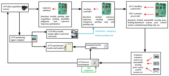
Figure 4.
The overall design principle of the automatic vertical parking experiment.
The safety of AVP is paramount, and there can be no mistakes; so, monitoring the upper computer is necessary. In this way, the driver can view the real-time parking situation. Here, the automatic vertical garage experiment was equipped with a driver in the vehicle and a person to guarantee the ground safety. The driver was responsible for the safety of the parking experiment and the trajectory control correction of the vehicle. The driver did not control the operation of the vehicle. The driver’s task was to send a stop command to the tracking controller if needed, and the tracking controller was responsible for the parking of the vehicle. The ground security person kept in touch with the driver and was responsible for observing the safety environment outside the vehicle. The security person was also responsible for taking aerial photos of the vehicle using the unmanned aerial vehicle (UAV). As shown in Figure 4, the experimental results and analysis of the automatic vertical parking were obtained using UAV aerial photography and the upper computer.
The experimental configuration was as follows. The time limit for the sensor data collection was 3.5 s, 1.5 s for the parking feasibility judgment, 12 s for optimizing the reference trajectory, and 25 s for the tracking control of the reference trajectory. The time limit for the tracking controller to control the parking of the vehicle at the end was 2 s, with 0.4 s for emergency braking, if needed. The UAV was a DJI Mavic 2 DJI “Yu” series (Dajiang, Shenzhen, China). The upper computer was a MacBook Pro 2016 core i5 @ 2.9 GHz (Apple Inc., San Francisco, CA, USA), and it communicated via Bluetooth. Two MPC555LFMZP40 chips (from Shenzhen Yixincheng Technology Co., LTD, Shenzhen, China) were used for the trajectory optimizer (whose functions included the parking data acquisition, parking feasibility judgment, and reference trajectory optimization) and the tracking controller (whose functions included the reference trajectory tracking control, the emergency parking stop, and the parking stop), respectively; two DSP28335 chips (Texas Instruments, Dallas, TX, USA) were used for the auxiliary control unit (ACU, whose functions included the air conditioner, an overload protecting device, communication, etc.) and the actuator power unit (APU, whose functions included braking, the automobile steering gear, the braking/dynamical system, the gear control system, etc.), respectively. Compared with the DSP28335 chip, the MPC555LFMZP40 chip has a more powerful computational performance; so, the specific trajectory optimizer and tracking controller had high-speed computational capability.
4.3. Results and Analysis of the Automatic Parking Experiment
To verify the optimization effect of the proposed parking optimization algorithm, with clear weather and no wind, the proposed IISSO, an IIMFO proposed in [15], the traditional shark smell optimization [18], the traditional moth flame optimization [22], an improved PSO proposed in [16], and the traditional PSO [23] were used to optimize the parking reference trajectory. Fuzzy proportional–integral–derivative (Fuzzy PID) control was selected as the reference trajectory tracking control mode of the above algorithms. To ensure a reasonable comparison of the performance differences, the optimization models of the optimization reference trajectory of the different algorithms were configured with the same parameters, as detailed in Table 1.

Table 1.
Parameter configuration of the automatic vertical parking optimization model.
To ensure that the experiment comparison results were fairly compared, the vehicle coverage areas at the fixed points of P4, P7, and P10 in the automatic parking tracking control process were selected for analysis and comparison, and their ordinate ranges were [5.95, 6.05] meters, [4.45, 4.55] meters, and [2.30, 2.50] meters, respectively. The experimental results of the automatic vertical parking included the trajectory optimization results and tracking control results displayed by the upper computer, as well as the UAV aerial images for the vehicle coverage areas at the fixed points in the tracking process. The optimized reference trajectory and tracking control curve of the whole parking process for the two AVP experiments are shown in Figure 5, Figure 6, Figure 7 and Figure 8, respectively. The display images of the upper computer and aerial photography images of the vehicle overlay areas at the three fixed points of the parking tracking control process for the two AVP experiments are shown in Figure 9, Figure 10, Figure 11 and Figure 12, respectively. The fixed point coordinates and path length results of the optimized trajectory curve and its tracking control curve can be seen in Table 2, Table 3, Table 4 and Table 5, respectively.
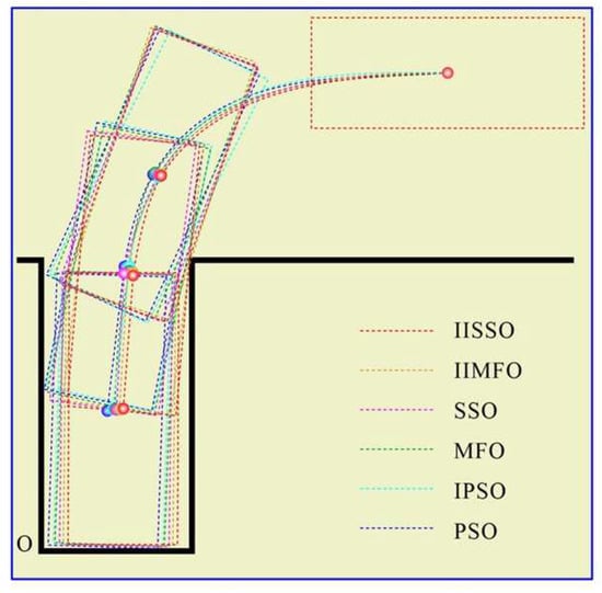
Figure 5.
Reference trajectory optimization curves for the AVP at the pre-selected points obtained via the upper computer (scene 1).
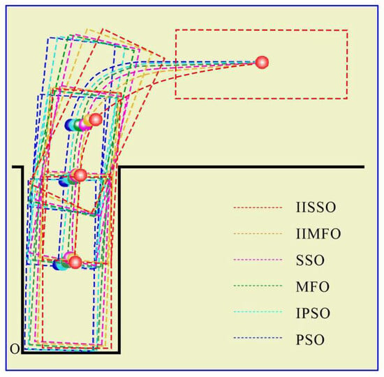
Figure 6.
Reference trajectory optimization curves for the AVP at the pre-selected points obtained via the upper computer (scene 2).
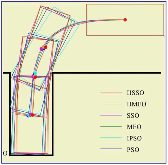
Figure 7.
Reference trajectory tracking control curves for the AVP at the pre-selected points obtained via the upper computer (scene 1).
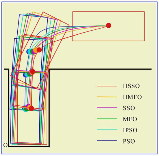
Figure 8.
Reference trajectory tracking control curves for the AVP at the pre-selected points obtained via the upper computer (scene 2).
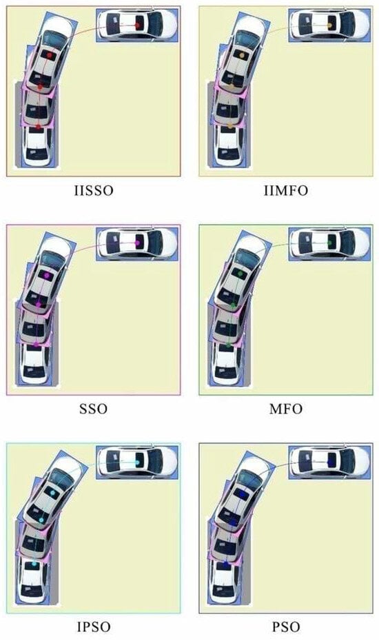
Figure 9.
Decomposition schematic diagram of the AVP at the pre-selected points obtained via the upper computer (scene 1).
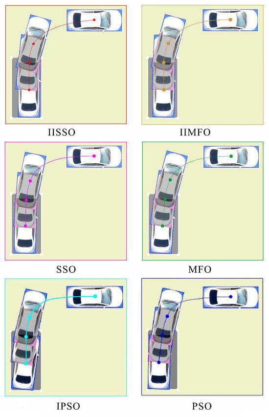
Figure 10.
Decomposition schematic diagram of the AVP at the pre-selected points obtained via the upper computer (scene 2).
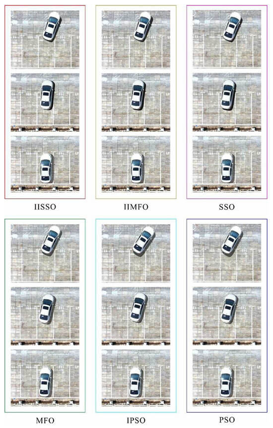
Figure 11.
Decomposition schematic diagram of the AVP at the pre-selected points obtained via the unmanned aerial camera (scene 1).
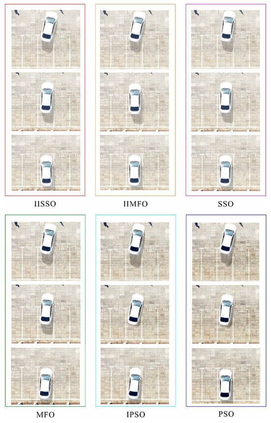
Figure 12.
Decomposition schematic diagram of the AVP at the pre-selected points obtained via the unmanned aerial camera (scene 2).

Table 2.
Reference trajectory optimization results for the AVP process (scene 1).

Table 3.
Reference trajectory tracking control results for the AVP process (scene 1).

Table 4.
Reference trajectory optimization results for the AVP process (scene 2).

Table 5.
Reference trajectory tracking control results for the AVP process (scene 2).
As shown in Table 2, Table 3, Table 4 and Table 5, the final position accuracy (called the parking point vector) is composed of the parking position and the parking inclination angle.
It can be seen from Figure 5, Figure 6, Figure 9 and Figure 10 that compared with the other optimization algorithms, the IISSO found a more ideal reference trajectory with a shorter path length, a lower expected parking inclination angle, and a lower parking position error. It can be seen from Figure 7 and Figure 8 that compared with the other optimization algorithms, on the basis of the same tracking control algorithm (fuzzy PID), the IISSO obtained more ideal tracking control results, with a shorter path length of the actual trajectory, a lower actual parking inclination angle, and a lower actual parking position error. From Figure 11 and Figure 12, we see that compared with the other optimization algorithms, on the basis of the same tracking control algorithm (fuzzy PID), the IISSO obtained a more ideal tracking control path, closer to the near side line of the garage, with a lower actual parking inclination angle. It can also be seen from Table 2 and Table 4 that compared with the other optimization algorithms, the IISSO found a more ideal reference trajectory, the path length of the reference trajectory was shorter, the berth tilt angle and expected parking position error were smaller, and the realization time of the IISSO’s optimization was also shorter. Table 4 shows that compared with the other optimization algorithms, on the basis of the same tracking control algorithm (fuzzy PID), the IISSO obtained a more ideal tracking control trajectory, the actual path length of the tracking control trajectory was shorter, and its actual parking inclination angle and actual parking position error were also smaller.
5. Conclusions
AVP has a wide range of practical applications in commercial, civil, military, etiquette, and other fields; however, its trajectory optimization is a multi-objective, non-linear, and extremely complex optimization problem. Hence, it is challenge to determine the ideal reference trajectory with collision avoidance and a smooth and short enough path length. In order to improve the optimization performance of AVP reference trajectories, an optimization model of AVP reference trajectories was constructed based on cubic spline interpolation, and an IISSO was proposed to solve the reference trajectory issues. Compared with the traditional AVP trajectory optimization algorithm, its superiority can be described as follows:
Firstly, a novel, reasonable, and feasible reference trajectory optimization model for AVP was established using the cubic spline interpolation method, which is helpful to solve the four practical problems of the poor obstacle avoidance performance of the reference trajectory, the low smoothness of the trajectory, the long path, and the large tilt degree of parking.
Secondly, in order to effectively heighten the global optimization performance of the shark optimization algorithm, refraction, Gaussian variation, and immune mechanisms were integrated into the shark optimization algorithm to effectively balance the computational intensity of the global exploration and local exploitation of the algorithm; hence, its global optimization performance was greatly improved.
In order to confirm the effectiveness of the proposed optimization algorithm IISSO, the AVP of real vehicles was conducted. The results of the real vehicle experiments indicate that the IISSO obtained significantly better AVP reference trajectories than the other optimization performance algorithms, and its actual tracking control effect was also significantly better.
However, there were several limitations to this study.
- Real-world parking scenes include dynamic obstacles (e.g., pedestrians and other vehicles). When there are sudden obstacles during parking, the AVP system will trigger the stop command; however, it does not have the ability to continue tracking control and avoid obstacles.
- Our research was limited to ordinary vehicles; hence, it is not applicable to special vehicles, such as trucks, heavy-duty vehicles, large vehicles, and small vehicles.
- There is still room for further improvement of the results, although compared with the existing results, our research results were improved.
- The research presented was still in the experimental stage, which required the configuration of a relatively complex and expensive AVP system; hence, we remain far from having a product that can be mass-produced.
Author Contributions
Conceptualization, investigation, resources, Y.C.; writing—original draft preparation, writing—review, Y.C. and L.W.; editing, supervision, language polishing, G.L., L.W. and B.X.; funding, Y.C., G.L. and L.W. All authors have read and agreed to the published version of the manuscript.
Funding
The authors declare that this study received funding from the National Natural Science Foundation of China (62341313); the Key Projects of Natural Science Research in Universities of Anhui Province, grant numbers (KJ2021A1138, 2023AH052354); the Chizhou University Nature Key Project, grant number (CZ2022ZRZ08); the Chizhou University Nature Transverse Project, grant numbers (2023HX0060, 2024HX0044); the General Project of the Natural Science Foundation of Inner Mongolia (2023MS06013); basic scientific research business expenses of colleges and universities directly under the Inner Mongolia Autonomous Region’s Plan to Improve the Scientific Research and Innovation Ability of Young Teachers (GXKY22125); the Inner Mongolia Minzu University Doctoral Research Initiation Fund Project (BS416); the Liaoning Provincial Department of Transportation Scientific Research Project, grant number (202344); and the Liaoning Provincial Department of Education Scientific Research Project, grant number (JYTMS20230038). The funder had the following involvement with the study: editing, supervision, language polishing.
Data Availability Statement
Data sharing is not applicable to this article.
Conflicts of Interest
Author Bing Xia was employed by Hangzhou Huayun Technology Co., Ltd. The remaining authors declare that the research was conducted in the absence of any commercial or financial relationships that could be construed as a potential conflict of interest.
Abbreviations
The following abbreviations are used in this manuscript:
| AVP | automatic vertical parking |
| IISSO | improved immune shark smell optimization |
| SSO | shark smell optimization |
| IIMFO | improved immune moth flame optimization |
| MFO | moth flame optimization |
| IPSO | improved particle swarm optimization |
| PSO | particle swarm optimization |
References
- Li, B.; Wang, K.; Shao, Z. Time-Optimal Maneuver Planning in Automatic Parallel Parking Using a Simultaneous Dynamic Optimization Approach. IEEE Trans. Intell. Transp. Syst. 2016, 17, 3263–3274. [Google Scholar] [CrossRef]
- Wang, J.; Li, J.; Yang, J.; Meng, X.; Fu, T. Automatic parking trajectory planning based on random sampling and nonlinear optimization. J. Frankl. Inst. 2023, 360, 9579–9601. [Google Scholar] [CrossRef]
- Suhr, J.K.; Jung, H.G. Automatic parking space detection and tracking for underground and indoor environments. IEEE Trans. Ind. Electron. 2016, 63, 5687–5698. [Google Scholar] [CrossRef]
- Chen, Q.; Gan, L.; Chen, B.; Liu, Q.; Zhang, X. Parallel Parking Path Planning Based on Improved Arctangent Function Optimization. Int. J. Automot. Technol. 2023, 24, 23–33. [Google Scholar] [CrossRef]
- Chai, R.; Tsourdos, A.; Savvaris, A.; Chai, S.; Xia, Y.; Chen, C.L.P. Multiobjective optimal parking maneuver planning of autonomous wheeled vehicles. IEEE Trans. Ind. Electron. 2020, 67, 10809–10821. [Google Scholar] [CrossRef]
- Zips, P.; Böck, M.; Kugi, A. Optimisation based path planning for car parking in narrow environments. Robot. Auton. Syst. 2016, 79, 1–11. [Google Scholar] [CrossRef]
- Ji, J.; Khajepour, A.; Melek, W.; Huang, Y. Path planning and tracking for vehicle collision avoidance based on model predictive control with multiconstraints. IEEE Trans. Veh. Technol. 2017, 66, 952–964. [Google Scholar] [CrossRef]
- Zhao, M.; Shen, T.; Wang, F.; Yin, G.; Li, Z.; Zhang, Y. Automatic Parking Control of Unmanned Vehicle Based on Switching Control Algorithm and Backstepping. IEEE ASME Trans. Mechatronics 2024, 25, 4116–4132. [Google Scholar]
- Gao, H.; Zhu, J.; Li, X.; Kang, Y.; Li, J.; Su, H. APTEN-Planner: Autonomous Parking of Semi-Trailer Train in Extremely Narrow Environments. IEEE Trans. Intell. Transp. Syst. 2022, 27, 1233–1243. [Google Scholar]
- Yang, H.; Xu, X.; Hong, J. Automatic Parking Path Planning of Tracked Vehicle Based on Improved A* and DWA Algorithms. IEEE Trans. Transp. Electrif. 2023, 9, 283–292. [Google Scholar] [CrossRef]
- Chai, R.; Liu, D.; Liu, T.; Tsourdos, A.; Xia, Y.; Chai, S. Deep Learning-Based Trajectory Planning and Control for Autonomous Ground Vehicle Parking Maneuver. IEEE Trans. Autom. Sci. Eng. 2023, 20, 1633–1647. [Google Scholar] [CrossRef]
- Chen, X.; Mai, H.; Zhang, Z.; Gu, F. A novel adaptive pseudospectral method for the optimal control problem of automatic car parking. Asian J. Control. 2022, 24, 1363–1377. [Google Scholar] [CrossRef]
- Cai, L.; Guan, H.; Zhou, Z.; Xu, F.; Jia, X.; Zhan, J. Parking Planning Under Limited Parking Corridor Space. IEEE Trans. Intell. Transp. Syst. 2022, 24, 1962–1981. [Google Scholar] [CrossRef]
- Han, I. Geometric Path Plans for Perpendicular/Parallel Reverse Parking in a Narrow Parking Spot with Surrounding Space. Vehicles 2022, 4, 1195–1208. [Google Scholar] [CrossRef]
- Chen, Y.; Wang, L.; Liu, G.; Xia, B. Automatic Parking Path Optimization based on Immune Moth Flame Algorithm for Intelligent Vehicles. Symmetry 2022, 14, 1923. [Google Scholar] [CrossRef]
- Chen, Y.; Qian, Y. Improved Particle Swarm Optimization Algorithm for Automatic Entering Parking Space Based on Spline Theory. In Proceedings of the 2nd International Conference on Computing and Data Science (CONF-CDS 2021), Stanford, CA, USA, 28–30 January 2021; Volume 28, pp. 136–143. [Google Scholar]
- Dyer, S.A.; Dyer, J.S. Cubic-spline interpolation 1. IEEE Instrum. Meas. Mag. 2001, 4, 44–46. [Google Scholar] [CrossRef]
- Abedinia, O.; Amjady, N.; Ghasemi, A. A new metaheuristic algorithm based on shark smell optimization. Complexity 2014, 21, 97–116. [Google Scholar] [CrossRef]
- Ahmadigorji, M.; Amjady, N. A multiyear DG-incorporated framework for expansion planning of distribution networks using binary chaotic shark smell optimization algorithm. Energy 2016, 102, 199–215. [Google Scholar] [CrossRef]
- Tizhoosh, H.R. Opposition-Based Learning: A New Scheme for Machine Intelligence. In Proceedings of the International Conference on Computational Intelligence for Modelling, Control & Automation, & International Conference on Intelligent Agents, Web Technologies & Internet Commerce, Vienna, Austria, 28–30 November 2005; pp. 695–701. [Google Scholar]
- Xu, L.; Li, Y.; Li, K.; Beng, G.; Jiang, Z.; Wang, C.; Liu, N. Enhanced Moth-flame Optimization Based on Cultural Learning and Gaussian Mutation. J. Bionic Eng. 2018, 15, 751–763. [Google Scholar] [CrossRef]
- Mirjalili, S. Moth-flame optimization algorithm: A novel nature-inspired heuristic paradigm. Knowl.-Based Syst. 2015, 89, 228–249. [Google Scholar] [CrossRef]
- Peng, H.; Li, R.; Cao, L.; Li, L. Multiple Swarms Multi-Objective Particle Swarm Optimization Based on Decomposition. Procedia Eng. 2011, 15, 3371–3375. [Google Scholar]
Disclaimer/Publisher’s Note: The statements, opinions and data contained in all publications are solely those of the individual author(s) and contributor(s) and not of MDPI and/or the editor(s). MDPI and/or the editor(s) disclaim responsibility for any injury to people or property resulting from any ideas, methods, instructions or products referred to in the content. |
© 2024 by the authors. Licensee MDPI, Basel, Switzerland. This article is an open access article distributed under the terms and conditions of the Creative Commons Attribution (CC BY) license (https://creativecommons.org/licenses/by/4.0/).