Article

A Robust Fixed-Time Sliding Mode Control for Quadrotor UAV

by
Jairo Olguin-Roque
,
Sergio Salazar
,
Iván González-Hernandez
and
Rogelio Lozano
*
UMI-LAFMIA, CINVESTAV, Ciudad de Mexico 07360, Mexico
*
Author to whom correspondence should be addressed.
Algorithms 2023, 16(5), 229; https://doi.org/10.3390/a16050229
Submission received: 17 February 2023 / Revised: 19 March 2023 / Accepted: 20 April 2023 / Published: 28 April 2023
(This article belongs to the Topic Safe and Secure Autonomous Systems)

Abstract

:
This paper proposes a robust algorithm based on a fixed-time sliding mode controller (FTSMC) for a Quadrotor aircraft. This approach is based on Lyapunov theory, which guarantees system stability. Nonlinear error dynamics techniques are used to achieve accurate trajectory tracking in the presence of disturbances. The performance of the FTSMC is compared with the typical non-singular terminal sliding mode controller (NTSMC) to evaluate its effectiveness. The numerical results show that FTSMC is more efficient than the typical NTSMC in disturbance reduction.

1. Introduction

UAVs (Unmanned Aerial Vehicles), also known as drones, have revolutionized the way in which various operations are carried out in different fields of industry. The ability of UAVs to fly at high altitudes and in hard-to-reach areas, combined with advanced sensor and camera technologies, allows inspection and surveillance tasks to be carried out with greater precision and safety [1,2]. In the field of precision agriculture, UAVs can be used to obtain detailed information on crop conditions, enabling more efficient land and water management [3,4].
Moreover, UAVs are also used to create detailed maps of specific terrains and geographical areas, which is of great help in activities such as infrastructure planning and natural resource management [5,6]. In natural disaster situations, UAVs can be used to carry out rapid and accurate assessments of damage and the needs of affected communities [7].
Furthermore, in the field of air transport of payloads, UAVs offer an economical and safe alternative for the delivery of supplies and materials to remote or inaccessible areas. In addition, the versatility and efficiency of UAVs make them indispensable tools in various areas of industry and society [8,9,10,11]. The following are just a few examples.
Proportional-Integral-Derivative (PID) control is a control technique commonly used in industry. Its implementation requires several iterative tunings of its parameters. In a recent study [12], a nonlinear PID controller for total thrust and torques applied to follow a desired trajectory of the Quadrotor aircraft was proposed.
This robust controller is highly adaptable to different types of UAVs and offers a promising approach for controlling aerial vehicles that require fast, accurate, and robust responses in challenging and dynamic situations.
On the other hand, the work in [13] compared the tracking capability of three different controllers in the design of a flight controller for a V-tail Quadrotor aircraft. The controllers compared were proportional derivative (PD), PID and sliding mode controller (SMC). According to their simulation results, the PD controller presented a steady-state error that was not corrected, which could be problematic in applications requiring high precision. In contrast, the SMC allowed the Quadrotor aircraft to quickly converge to the desired point.
In this context, controllers based on sliding modes present an inherent phenomenon called chattering, which is a problem for engineers because it wears out and reduces the useful life of the actuators in a given process [14]. This effect is characterized by rapid oscillations and high frequency in the control signal. In addition, this phenomenon can cause problems in the operation of the system, such as noise high-frequency generation and wear on mechanical components, as well as degradation of the accuracy of the system response in some cases. For this reason, chattering has been studied to find solutions to reduce this effect.
Among the solutions proposed to reduce chattering in sliding mode control systems are the use of filtering techniques, the implementation of soft control laws, the modification of the controller gain and the design of adaptive control algorithms. These solutions have proven to be effective in reducing chattering and improving control system performance [15].
In the case of UAVs, chattering can be especially critical because these systems often operate in variable conditions and dynamic environments. Therefore, it is important to consider effective solutions to reduce chattering in UAV control systems, which can improve the navigation accuracy and energy efficiency of the system.
Therefore, this research focuses on one of the controls that have been investigated in the literature to improve the accuracy and robustness of flight control for UAVs. In reference [16], an SMC approach based on a fixed-time disturbance observer is proposed to improve flight control in the presence of external disturbances. Similarly, reference [17] presents a backstepping-sliding mode control using a closed-loop identification for Quadrotor aircraft trajectory tracking.
However, the problem of finite-time tracking control has been considered in many types of research. In reference [18], the authors perform an altitude control for a Quadrotor aircraft using an integral slip control (ISM) approach which aims to improve the robustness and accuracy of the altitude controller. Something similar is used in reference [19], where a sliding mode control approach is also presented to improve the accuracy and robustness of attitude and altitude control for a Quadrotor aircraft, while in references [20,21], the author focuses on trajectory tracking control for a Quadrotor aircraft using an approach combining a dynamic surface controller (DSC) and an extended state observer (ESO). Then, in reference [22], an adaptive sliding mode controller approach is proposed to improve the accuracy of the path tracking with rejection of external disturbances. Furthermore, in reference [23], the authors propose a robust adaptive non-singular fast terminal sliding mode tracking control for an uncertain Quadrotor UAV subject to disturbances.
Similarly, an adaptive controller was used in reference [24] to adjust the parameters of the SMC in real time, further improving the system’s ability to adapt to adverse environmental conditions. The SMC technique is used to improve the robustness and adaptability of flight control to external disturbances such as gusts of wind.
In the same way, reference [25] deals with the characteristic chatter phenomenon of slider mode control. The characteristic oscillation of this type of control can affect the trajectory following tracking, so a sliding mode controller with integral action is proposed to minimize the vibration and improve the trajectory-tracking accuracy of the UAV.
The approach proposed in reference [26] uses an improved sliding mode speed control that combines a smoothed switching function and a low-pass filter to attenuate noise and improve motor speed control accuracy, while in reference [27], a control method is proposed where the estimated angles converge to the desired value for the scope of the orientation and therefore execute the tracking of the vehicle position to the given reference.
Then, in reference [28] also uses an observer based on a sliding mode controller to stabilize a Quadrotor aircraft in hover flight in outdoor environment, while reference [29] uses an observer to estimate disturbances and a finite-time tracking control law to achieve robust trajectory tracking in an aerial vehicle. In addition, in reference [30] a robust control based on fixed-time sliding modes is also used to control the attitude of a Quadrotor aircraft in the presence of external disturbances.
The contribution of this article is the implementation of a control algorithm based on a fixed-time sliding mode controller (FTSMC) to improve trajectory-tracking errors to zero, providing robust results in the presence of external disturbances such as gusts of wind.
FTSMC is a control technique used in nonlinear dynamic systems such as Quadrotor aircraft that allows for reaching a stable control state at a fixed time. This technique uses a sliding surface to maintain the system in a steady state, even in the presence of disturbances or uncertainties in the system [31].
The FTSMC is an advantageous control algorithm to apply in Quadrotor aircraft due to its ability to provide robust and fast real-time control performance. This algorithm uses a control law based on a sliding surface to reduce the error between the desired output and the actual system output. In addition, this strategy reduces external disturbances and considers the non-modeling dynamics.
Therefore, FTSMC is a powerful control technique for Quadrotor aircraft that allows for achieving high precision and stability in the navigation and positioning of these unmanned aerial vehicles.
At the same time, the results obtained have shown that the implemented FTSMC provides robustness by tracking the trajectory more precisely to the desired reference with an improvement capacity for the rejection of external disturbances that affect the aerial vehicle. This proposed algorithm is developed using the nonlinear errors of the Quadrotor aircraft dynamics. Finally, the simulations obtained from the proposed control are compared with an NTSMC (non-singular terminal sliding mode controller) to verify its effectiveness and good performance of the robust control algorithm proposed in this paper.
This paper is organized as follows: Section 2 presents the dynamic model of the Quadrotor aircraft, Section 3 describes the stabilization of a robust algorithm, which is divided into two parts, Section 3.1 presents the desired modes for the Y-axis dynamics of the vertical displacement, and Section 3.2 presents the desired modes for the X-axis dynamics of the horizontal displacement; the comparison of the proposed control FTSMC with NTSMC and the numerical simulations is visualized in Section 4. Finally, the conclusions are presented in Section 5.

2. Quadrotor Aircraft Modelling

The Quadrotor aircraft shown in Figure 1, is an unmanned aerial vehicle that has become increasingly popular in recent years due to its versatility and ability to perform a wide variety of tasks. This type of drone uses four electric motors to generate the power needed to stay in the air and control its movement in different directions.
Each motor in the Quadrotor aircraft is responsible for generating a force known as Thrust, which allows the drone to stay in the air and move in different directions. The four motors work together to control the Yaw (vertical axis turn), Roll (horizontal axis turn), and Pitch (lateral axis turn) movements of the drone, allowing it to perform precise maneuvers and respond to instructions from the pilot or the automatic control system.
The control of the four motors in a Quadrotor aircraft is essential to achieve balance and stability in the air since any change in the speed or force of one of the motors directly affects the drone’s movement in all directions. Therefore, precision and careful control of all four motors are critical to achieving stable and safe flight.
Currently, one of these types of aerial vehicles is the IMU, which uses GPS, lidar, etc.; this allows knowledge of the position and attitude. However, for UAV navigation to be accurate and efficient, it is necessary to have a geodetic frame of reference that allows the device to be in a three-dimensional coordinate system.
The Quadrotor aircraft shows the simplified model of [32], which satisfies the following perturbed dynamic equations:
x ¨ = u sin θ + Γ x y ¨ = u cos θ sin ϕ + Γ y z ¨ = u cos θ cos ϕ m g + Γ z θ ¨ = τ θ + Γ θ ϕ ¨ = τ ϕ + Γ ϕ ψ ¨ = τ ψ + Γ ψ
where u is the total thrust, τ θ , τ ϕ and τ ψ are the torques of rotational movements, m is the mass, I is the inertia moment, x is the horizontal displacement, y is the vertical displacement, z is the altitude displacement and g is the gravitational acceleration. Γ x , Γ y and Γ z represent the perturbations of the translational motions of the x, y and z axes; now in Γ θ , Γ ϕ and Γ ψ represent the perturbations of the rotational motions of the angles θ , ϕ and ψ . All perturbations are external. In this model, we do not contemplate perturbations in the translational dynamics ( y x ) due to this being the main focus of analysis, since we propose to use visual information to obtain references ( x ,   y ); for this, we will have a value of Γ z 0 , and later we will use GPS information to stabilize the z-axis.

3. Robust Stabilization

The altitude z can be stabilized by using the following thrust control input.
u = m ( g + r ) cos θ cos ϕ
where r is defined as:
r = k z 1 z ˙ k z 2 ( z z d )
where k z is a positive constant and z d is the desired altitude; notice from Equation (2) and the above that if | θ | < π 2 , then u > 0 .
The yaw angular position can be controlled by applying a sliding mode approximation,
τ ψ = ψ ˙ k ψ sgn ψ ˙ + β ψ
where k ψ | Γ ψ | , β and k ψ > 0; thus, Equation (1) can be rewritten as:
x ¨ = tan θ ( g + r ) cos ϕ + Γ x
For the Y-axis, it is:
y ¨ = tan ϕ ( g + r ) + Γ y
Now for the Z-axis, we obtain:
z ¨ = r + Γ z
Subsequently, for the rotation angles we have:
θ ¨ = τ θ + Γ θ
ϕ ¨ = τ ϕ + Γ ϕ
ψ ¨ = τ ψ + Γ ψ

3.1. Desired Modes for the y-Axis Dynamics of the Vertical Displacement

From Equation (5b), it follows that:
y ¨ = tan ϕ ( g + r ) ± tan ϕ d ( g + r ) + Γ y
where we have
y ¨ = tan ϕ d ( g + r ) + e y ( g + r ) + Γ y
and the nonlinear error is:
e y = tan ϕ tan ϕ d
In addition, tan ϕ d is considered as the desired virtual control input.
The following variable is defined.
ν y = y ˙ + k y ( y y d )
Differentiating, we obtain ν y .
ν ˙ y = y ¨ + k y y ˙
with k y > 0 and after introducing Equation (8):
ν ˙ y = y ¨ + k y y ˙ = ( tan ϕ d ( g + r ) + e ( g + r ) ) + k y y ˙ + Γ y
in order to obtain the following expression.
ν ˙ y = ν y + e y
where the error e y is:
e y = e y ( g + r )
We proposed the desired virtual control input tan ϕ d such that:
( g + r ) tan ϕ d + e y ( g + r ) + k y y ˙ = ν y + e y ( g + r ) + Γ y
getting tan ϕ d .
( g + r ) tan ϕ d = ν y k y y ˙
From Equations (9), (14) and (16), it follows that:
e y = tan ϕ tan ϕ d ( g + r ) = tan ϕ ( g + r ) + ν y + k y y ˙ + Γ y
Differentiating the above:
e ˙ y = ϕ ˙ cos 2 ϕ ( g + r ) + tan ϕ r ˙ + ν ˙ y + k y y ¨ + Γ ˙ y
Differentiating again and introducing Equation (5b), it follows that:
e ¨ y = 2 tan ϕ cos 2 ϕ ϕ ˙ 2 ( g + r ) + 2 ϕ ˙ cos 2 ϕ r ˙ + tan ϕ r ¨ + ν ¨ y + k y y ( 3 ) + ( g + r ) τ ϕ + Γ ϕ cos 2 ϕ + Γ ¨ y
It is important to mention that Γ ¨ y is the double derivative of the perturbation in the translational movement of y and Γ ϕ is the perturbation in the rotational movement of ϕ . Notice that the second- and third-order derivatives of r , x and ν x which appear above can be computed as a function of their first-order derivatives as follows.
From Equations (3) and (5c):
r = k z z ˙ k z ( z z d ) r ˙ = k z r k z z ˙ r ¨ = k z r ˙ k z r ¨
where z d > 0 is a constant, from Equation (5b):
y ¨ = tan ϕ ( g + r ) + Γ y y ( 3 ) = ϕ ˙ cos 2 ϕ ( g + r ) + tan ϕ r ˙ + Γ ˙ y
and from Equation (10) is substituted.
ν y = y ˙ + k y ( y y d ) ν ˙ y = y ¨ + k y y ˙ ν ¨ y = y ( 3 ) + k y y ¨
In view of Equation (19), a sliding surface s e y is proposed:
s e y e y ˙ + β y e y
Then, we propose a Lyapunov function at Equation (23):
V = 1 2 s e y 2
Differentiating the above, we have
V ˙ = s ˙ e y = s e y ( e ¨ y + β y e ˙ y ) , β y > 0
The following robust sliding mode controller is now proposed.
e ¨ y + β y e ˙ y = k 1 y sgn ( s e y ) k 2 y | s e y | α y sgn ( s e y ) k 3 y | s e y | γ y sgn ( s e y ) k 4 y y
Then, it leads to:
V ˙ = 2 k 1 y | s e y | 2 k 2 y | s e y | α y + 1 2 k 3 y | s e y | γ y + 1 2 k 4 y y 2 2 k 1 y δ y | s e y | 2 k 2 y | s e y | α y + 1 2 k 1 y δ y V ( s e y ) 1 2 2 k 2 y V ( s e y ) α y + 1 2
The corresponding gains of this axis are the same as in the following section.
Let us now obtain τ ϕ and add a sliding mode controller.
τ ϕ = 1 g + r cos 2 ϕ [ k 1 y sgn ( s e y ) k 2 y | s e y | α y sgn ( s e y ) k 3 y | s e y | γ y sgn ( s e y ) k 4 y y β y e ˙ y
2 tan ϕ cos 2 ϕ ϕ ˙ 2 ( g + r ) 2 ϕ ˙ cos 2 ϕ r ˙ tan ϕ r ¨ ν ¨ y k y y ( 3 ) Γ ϕ Γ ¨ y ]
where δ y is external perturbation such that | Γ ϕ + Γ ¨ y | < δ y for a given δ y > 0 ; then it follows that e y 0 on a fixed-time and from Equation (13):
V y 0
Afterwards from Equation (10):
y y d
and
ϕ d 0
Therefore, from Equation (16):
ϕ ϕ d
It is worth noting that the X and Y trajectories will be used by artificial vision and then analyzed by applying a low-pass filter that will allow us to filter the input disturbance in the y-axis information.

3.2. Desired Modes for the x-Axis Dynamics of the Horizontal Displacement

From Equation (5a):
x ¨ = tan θ ( g + r ) cos ϕ + Γ x
Assuming that cos ϕ must have a value close to 0 because the y-axis is stabilized in a fixed-time, the Equation (29) is:
x ¨ = tan θ ( g + r ) + Γ x
Then, from Equation (5a) it follows that:
x ¨ = tan θ d ( g + r ) + e x ( g + r ) + Γ x
where we obtain:
e x = tan θ tan θ d
and follows the same procedure presented in the previous subsection. The following variable is defined and it is added that k x > 0.
ν x = x ˙ + k x ( x x d )
and also by defining the variable s x .
ν ˙ x = x ¨ + k 4 x ˙
Subsequently, the same y-axis methodology is performed to obtain e x , e ˙ x and e ¨ x on the x-axis.
e x = tan θ ( g + r ) + ν x + k x x ˙ + Γ x
Differentiating the above:
e ˙ x = θ ˙ cos 2 θ ( g + r ) + tan θ r ˙ + ν ˙ x + k x x ¨ + Γ ˙ x
Differentiating again and introducing Equation (5a), it follows that:
e ¨ x = 2 tan θ cos 2 θ θ ˙ 2 ( g + r ) + 2 θ ˙ cos 2 θ r ˙ + tan θ r ¨ + ν ¨ x + k x x ( 3 ) + ( g + r ) τ θ + Γ θ cos 2 θ + Γ ¨ x
where Γ ¨ x is the double derivative of the perturbation in the translational movement of x and Γ θ is the perturbation in the rotational movement of θ . In view of Equation (37), we propose a sliding surface s e y :
s e x e x ˙ + β x e x
Then, a Lyapunov function is proposed:
V = 1 2 s e x 2
Differentiating the above:
V ˙ = s ˙ e x = s e x ( e ¨ x + β x e ˙ x ) , β x > 0
The following sliding mode controller is proposed:
e ¨ x + β x e ˙ x = k 1 x sgn ( s e x ) k 2 x | s e x | α x sgn ( s e x ) k 3 x | s e x | γ x sgn ( s e x ) k 4 x x
Finally, we have that:
τ θ = 1 g + r cos 2 ϕ [ k 1 x sgn ( s e x ) k 2 x | s e x | α x sgn ( s e x ) k 3 x | s e x | γ x sgn ( s e x ) k 4 x x e ˙ x
2 tan θ cos 2 θ θ ˙ 2 ( g + r ) 2 θ ˙ cos 2 θ r ˙ tan θ r ¨ ν ¨ x k x x ( 3 ) Γ θ Γ ¨ x ]
where δ x is an external perturbation such that | Γ θ + Γ ¨ x | < δ x for a given δ x > 0 .

4. Numerical Simulation Results

In this section, the results obtained are validated by numerical simulations and a comparison is made with the proposed NTSMC algorithm. This will allow us to determine the efficiency and superiority of the trajectory-tracking controller by visualizing the fast response speed, high tracking accuracy and minimization of perturbation; the following controller is compared concerning our proposed algorithm. To verify the robustness of the proposed control algorithm, the Dryden model has been implemented in the simulations in order to recreate a real environment with gusts of wind that could affect the trajectory of the aerial vehicle.
The Dryden wind model has become a valuable tool in the development and testing of UAVs, as it allows engineers to study and better understand how wind affects vehicle behavior and stability in different situations. By creating scaled-down models of UAVs and testing them in wind tunnels, engineers can measure and analyze the aerodynamic forces acting on the vehicle in different wind conditions.
These tests allow engineers to make improvements to the UAV design to maximize stability and maneuverability, reduce energy consumption and improve flight efficiency and safety. Overall, the use of the Dryden wind model has become an essential tool in creating and improving UAVs, enabling the development of more advanced and effective aerial vehicles for a wide variety of applications [33].
Non-singular terminal mode sliding control (NTSMC) is a highly accurate and robust control technique that has been successfully used in a wide range of applications. NTSMC combines the advantages of sliding mode sliding control (SMC) and terminal mode control (TMC) to achieve accurate and fast control of dynamic systems.
Compared with conventional SMC, NTSMC has the advantage of avoiding the problem of the singularity phenomenon, which may occur when the system is close to its equilibrium point. In addition, NTSMC can guarantee the global convergence of the system to its equilibrium point, even when the system model is uncertain or nonlinear.
The NTSMC was published in reference [34], where a nonlinear dynamical system is expressed as follows:
x ˙ 1 = x 2 x ˙ 2 = f ( x ) + g ( x ) + b ( x ) u
where x = x 1 , x 2 T is the system state vector, f ( x ) is the smooth nonlinear function of x and g ( x ) represents the uncertainties and perturbations satisfying g ( x ) l g where l g > 0 , and u is the scalar control input.
The proposed NTSMC model is described as follows:
s = x 1 + 1 β x 2 p / q
where β > 0 is a design constant, and p and q are positive odd integers, which satisfy the following condition:
p > q
For system (43) with the NTSMC (44), the obtained control input is:
u = b 1 ( x ) f ( x ) + β q p x 2 2 p / q + l g + η sgn ( s )
where 1 < p/q < 2, η > 0 ; stability proof is shown in reference [34].
Now, to represent the NTSMC control in a Quadrotor aircraft, the sliding variable sy is expressed as follows:
s y = e y + 1 β y e y p y / q y
Defining:
e y = y d y
differentiating twice:
e ¨ y = y ¨ d y ¨
and from Equation (5b) and considering that r converges to 0 after a certain time.
e ¨ y = y ¨ d g ϕ + Γ y
Then, proposing ϕ d y as the virtual input of the system (50), e ¨ y converges to 0 based on [34].
ϕ d y = 1 g ( B y q y p y e y + ( l g y + η y ) sgn ( s y ) y ¨ d )
For the sliding variable, s ϕ is represented as:
s ϕ = e ϕ + 1 β ϕ e ϕ p ϕ / q ϕ
Now defining:
e ϕ = ϕ d y ϕ
differentiating twice:
e ¨ ϕ = ϕ ¨ d y ϕ ¨
and from Equation (6b):
e ¨ ϕ = ϕ ¨ d y τ ϕ + Γ ϕ
then, proposing ϕ d ϕ as the virtual input of the system (55).
ϕ v ϕ = τ ϕ B ϕ q ϕ p ϕ e ϕ + l g ϕ + η ϕ sgn s ϕ ϕ ¨ d y
It is important to clarify that e ¨ ϕ converges to 0 based on reference [34]; we will use for Y-axis and pitch controls the same procedure used in the previous section for roll and X-axis control.
To evaluate the effectiveness, numerical results have been performed using simulation tools such as Matlab. In addition, we compare the proposed FTSMC with the typical NTSMC in simulations using the same parameter values.
The objective of the proposed control is to achieve precise performance of the Quadrotor aircraft in the position and attitude in different flight conditions. The simulation results show that the FTSMC can successfully regulate the aerial vehicle, even in the presence of disturbances, noise and parasite dynamics. The Table 1 shows the parameters and initial conditions.
It is important to emphasize that we use the same parameter values and perturbations for each of the controllers in order to obtain a better result in the comparison and to identify the superiority of our proposed control algorithm.
The trajectory tracking performance of the proposed fixed-time sliding mode control (FTSMC) method is compared with that of the non-singular terminal sliding mode control (NTSM). The results of the comparison of the FTSMC and NTSMC controllers are shown in Figure 2, Figure 3, Figure 4 and Figure 5.
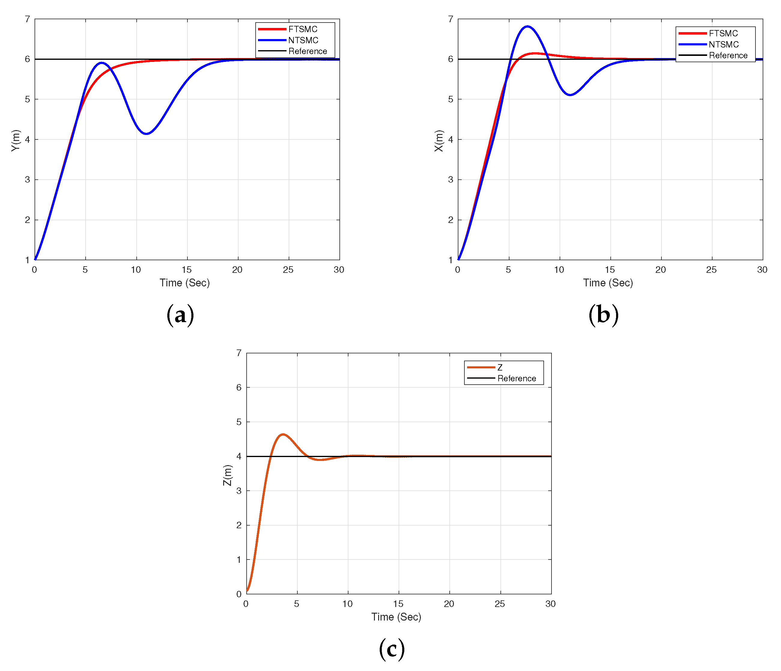
Figure 2a shows the convergence of the y axis displacement to the desired y d trajectory; the proposed FTSMC controller has a higher response, while the NTSMC controller lags by a few seconds. It is important to mention that both have the same gains of the Γ y perturbation. Figure 2b shows the convergence of the x-axis displacement to the desired x d trajectory. The proposed FTSMC controller also performs better compared to the NTSMC controller, both with a Γ x perturbation, and Figure 2c shows the convergence to the desired altitude of 4 m with a perturbation of Γ z . Our proposal can provide higher tracking accuracy and less vibration at the control input. As we can see, the proposed FTSMC controller can provide fast convergence to the desired positions.
Figure 3a shows that the FTSMC control converges in a period of time of 12 s. However, the NTSMC has longer convergence time and a small chattering occurs in both Γ ϕ and θ . Figure 3b also presents a convergence of the FTSMC at about 10 s while NTSMC converges in 18 s, both with a perturbation of Γ θ . Finally, Figure 3c presents its convergence to the desired trajectory with a perturbation of Γ ψ .
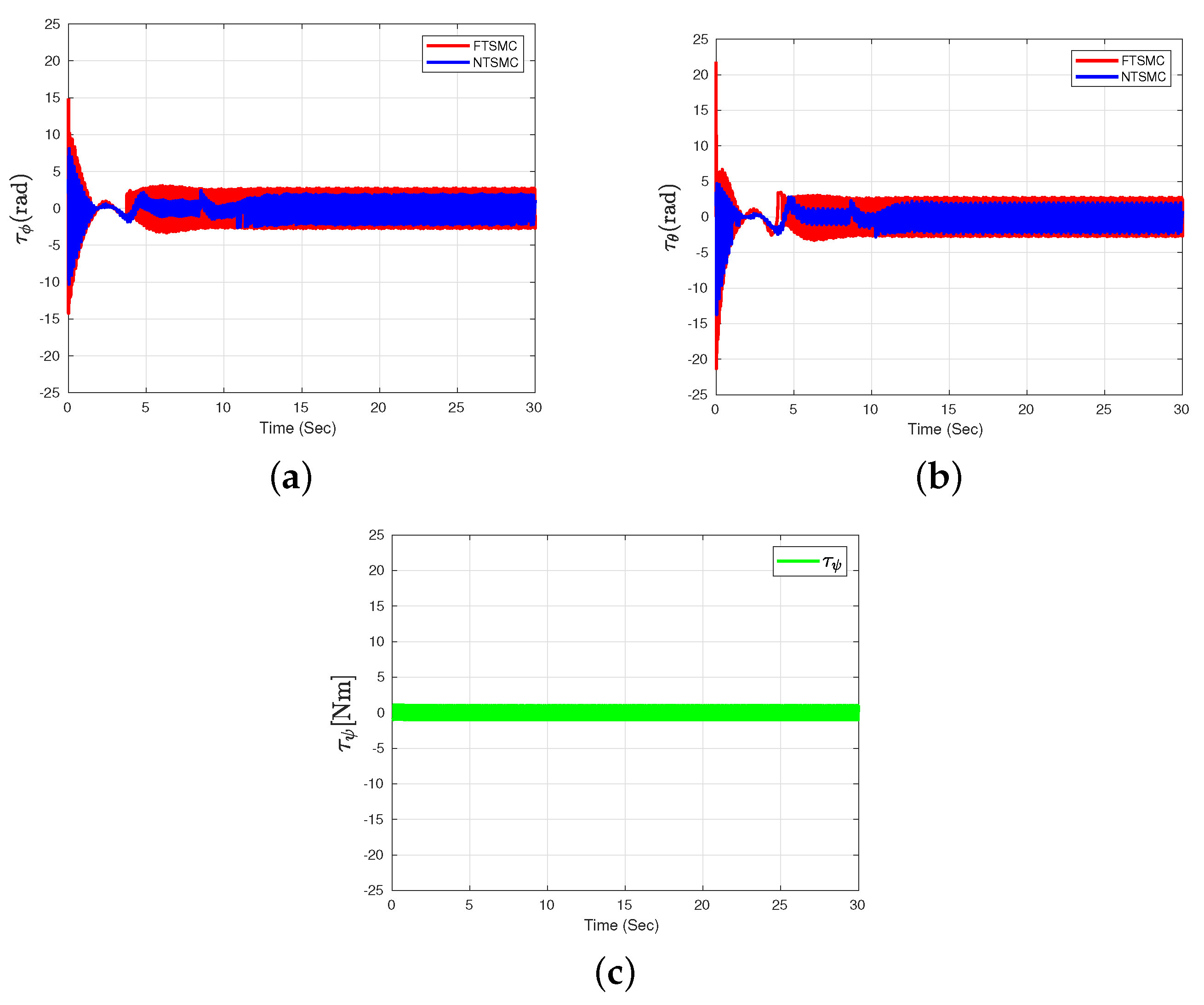
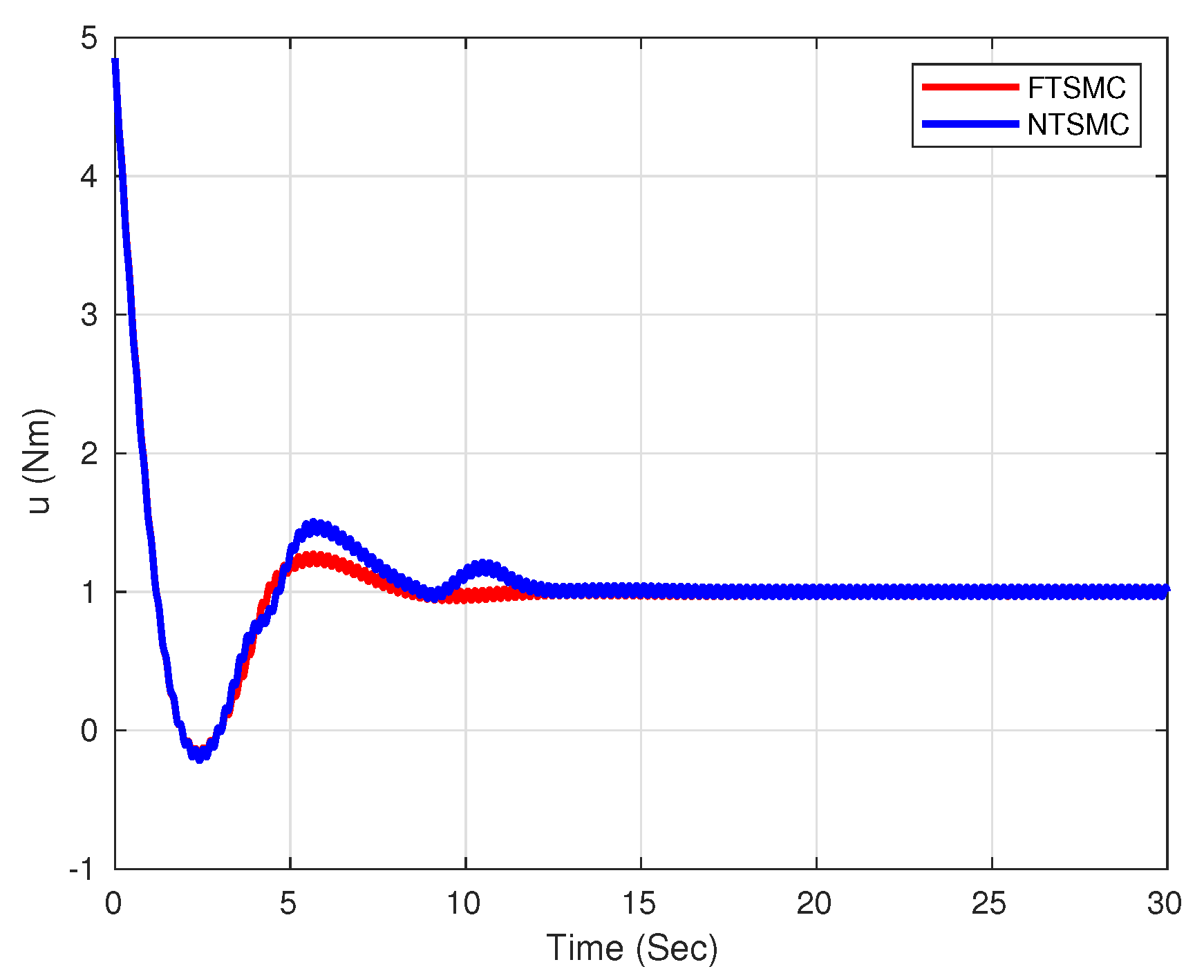
Figure 4a,b shows the behavior of the control input τ ϕ of both FTSMC and NTSMC controls, and τ θ for both controls FTSMC and NTSMC where the chattering effect is presented. τ ψ is shown in Figure 4c. Finally, the result of the simulation of the control input u is shown in Figure 5; the values of the added perturbations are presented in Table 1.

5. Discussion

This paper presents a control algorithm based on a fixed-time sliding mode controller using the dynamics of nonlinear errors on the trajectories ( x , y ) of the Quadrotor aircraft. The reduced dynamic model of the aerial vehicle is employed.
To improve the performance of the dynamics of the translation system, a nonlinear sliding surface is used to reduce the convergence time and the aerial vehicle tracks the desired position of x d , y d and z d . Furthermore, the translational movements of the X Y and rotational axes ( ϕ d , θ d ) are calculated.
A Lyapunov function is also used to demonstrate the stabilization of each axis of the Quadrotor aircraft; we assume that between the axes there is a coupling which disappears by the robust algorithm proposed.
Numerical simulation results are performed to quantify the performance of the control, which shows that the designed control algorithm improves convergence response time, accuracy and robustness while outperforming the NTSMC controller and reducing chattering.
In future work, we seek to improve accuracy in the measurement of the position and attitude of a Quadrotor aircraft. This improvement will be achieved by increasing the number of sensors used to obtain a better performance in the mission to be executed, such as artificial vision, lidar, etc.

Author Contributions

Project administration, I.G.-H.; supervision, S.S.; conceptualization, R.L.; investigation, J.O.-R. All authors have read and agreed to the published version of the manuscript.

Funding

This research received no external funding.

Institutional Review Board Statement

Not applicable.

Informed Consent Statement

Not applicable.

Data Availability Statement

Not applicable.

Acknowledgments

We thank CONACYT of México for its support through project 316256. “Laboratorio Nacional en Vehiculos Autonomos y Exoesqueletos LANAVEX”.

Conflicts of Interest

The authors declare no conflict of interest.

References

  1. Mishra, B.; Garg, D.; Narang, P.; Mishra, V. Drone-surveillance for search and rescue in natural disaster. Comput. Commun. 2020, 156, 1–10. [Google Scholar] [CrossRef]
  2. Alotaibi, E.T.; Alqefari, S.S.; Koubaa, A. LSAR: Multi-UAV Collaboration for Search and Rescue Missions. IEEE Access 2019, 7, 55817–55832. [Google Scholar] [CrossRef]
  3. Daponte, P.; Vito, L.D.; Glielmo, L.; Iannelli, L.; Liuzza, D.; Picariello, F.; Silano, G. A review on the use of drones for precision agriculture. IOP Conf. Ser. Earth Environ. Sci. 2019, 275, 012022. [Google Scholar] [CrossRef]
  4. Singh, C.; Mishra, R.; Gupta, H.P.; Kumari, P. The Internet of Drones in Precision Agriculture: Challenges, Solutions, and Research Opportunities. IEEE Internet Things Mag. 2022, 5, 180–184. [Google Scholar] [CrossRef]
  5. Arjomandi-Nezhad, A.; Moeini-Aghtaie, M.; Fotuhi-Firuzabad, M.; Aminifar, F. Budget-constrained drone allocation for distribution system damage assessment. IET Smart Grid 2022, 5, 42–50. [Google Scholar] [CrossRef]
  6. Andrade, S.D.; Saltos, E.; Nogales, V.; Cruz, S.; Lee, G.; Barclay, J. Detailed Cartography of Cotopaxi’s 1877 Primary Lahar Deposits Obtained by Drone-Imagery and Field Surveys in the Proximal Northern Drainage. Remote Sens. 2022, 14, 631. [Google Scholar] [CrossRef]
  7. Wu, B.; Fu, R.; Chen, J.; Zhu, J.; Gao, R. Research on Natural Disaster Early Warning System Based on UAV Technology. IOP Conf. Ser. Earth Environ. Sci. 2021, 787, 012084. [Google Scholar] [CrossRef]
  8. Sankaranarayanan, V.N.; Roy, S.; Baldi, S. Aerial Transportation of Unknown Payloads: Adaptive Path Tracking for Quadrotors. In Proceedings of the 2020 IEEE/RSJ International Conference on Intelligent Robots and Systems (IROS), Las Vegas, NV, USA, 25 October 2020–24 January 2021; pp. 7710–7715. [Google Scholar] [CrossRef]
  9. Sankaranarayanan, V.N.; Yadav, R.D.; Swayampakula, R.K.; Ganguly, S.; Roy, S. Robustifying Payload Carrying Operations for Quadrotors Under Time-Varying State Constraints and Uncertainty. IEEE Robot. Automat. Lett. 2022, 7, 4885–4892. [Google Scholar] [CrossRef]
  10. Ganguly, S.; Sankaranarayanan, V.N.; Suraj, B.V.S.G.; Dev Yadav, R.; Roy, S. Efficient Manoeuvring of Quadrotor under Constrained Space and Predefined Accuracy. In Proceedings of the 2021 IEEE/RSJ International Conference on Intelligent Robots and Systems (IROS), Prague, Czech Republic, 27 September–1 October 2021; pp. 6352–6357. [Google Scholar] [CrossRef]
  11. Sankaranarayanan, V.N.; Roy, S. Introducing switched adaptive control for quadrotors for vertical operations. Opt. Control Appl. Meth. 2020, 41, 1875–1888. [Google Scholar] [CrossRef]
  12. Golnaraghi, F.; Kuo, B.C. Automatic Control Systems; McGraw-Hill Education: New York, NY, USA, 2017. [Google Scholar]
  13. Castillo-Zamora, J.J.; Camarillo-Gomez, K.A.; Perez-Soto, G.I.; Rodriguez-Resendiz, J. Comparison of PD, PID and sliding-mode position controllers for V–tail quadcopter stability. IEEE Access 2018, 6, 38086–38096. [Google Scholar] [CrossRef]
  14. Svečko, R.; Gleich, D.; Sarjaš, A. The Effective Chattering Suppression Technique with Adaptive Super-Twisted Sliding Mode Controller Based on the Quasi-Barrier Function; An Experimentation Setup. Appl. Sci. 2020, 10, 595. [Google Scholar] [CrossRef]
  15. Liang, Y.; Zhang, D.; Li, G.; Wu, T. Adaptive Chattering-Free PID Sliding Mode Control for Tracking Problem of Uncertain Dynamical Systems. Electronics 2022, 11, 3499. [Google Scholar] [CrossRef]
  16. Ullah, I.; Pei, H.L. Fixed Time Disturbance Observer Based Sliding Mode Control for a Miniature Unmanned Helicopter Hover Operations in Presence of External Disturbances. IEEE Access 2020, 8, 73173–73181. [Google Scholar] [CrossRef]
  17. Parsa, A.; Kalhor, A.; Atashgah, M.A. Backstepping-Sliding mode Control Performance Enhancement using Close Loop Identification for Quadrotor Trajectory Tracking. In Proceedings of the 2017 5th RSI International Conference on Robotics and Mechatronics (ICRoM), Tehran, Iran, 25–27 October 2017; pp. 286–291. [Google Scholar] [CrossRef]
  18. González-Hernández, I.; Salazar, S.; Rodríguez-Mata, A.E.; Muñoz-Palacios, F.; López, R.; Lozano, R. Enhanced Robust Altitude Controller via Integral Sliding Modes Approach for a Quad-Rotor Aircraft: Simulations and Real-Time Results. J. Intell. Robot. Syst. Theory Appl. 2017, 88, 313–327. [Google Scholar] [CrossRef]
  19. Abci, B.; Zheng, G.; Efimov, D.; Najjar, M.E.B.E. Robust Altitude and Attitude Sliding Mode Controllers for Quadrotors; Elsevier B.V.: Amsterdam, The Netherlands, 2017; Volume 50, pp. 2720–2725. [Google Scholar] [CrossRef]
  20. Shao, X.; Liu, J.; Cao, H.; Shen, C.; Wang, H. Robust dynamic surface trajectory tracking control for a quadrotor UAV via extended state observer. Int. J. Robust Nonlin. Control 2018, 28, 2700–2719. [Google Scholar] [CrossRef]
  21. Huang, T.; Huang, D.; Wang, Z.; Shah, A. Robust tracking control of a quadrotor uav based on adaptive sliding mode controller. Complexity 2019, 2019, 7931632. [Google Scholar] [CrossRef]
  22. Labbadi, M.; Cherkaoui, M. Robust adaptive nonsingular fast terminal sliding-mode tracking control for an uncertain quadrotor UAV subjected to disturbances. ISA Trans. 2020, 99, 290–304. [Google Scholar] [CrossRef]
  23. Hassani, H.; Mansouri, A.; Ahaitouf, A. A new robust adaptive sliding mode controller for quadrotor UAV flight. In Proceedings of the 2020 IEEE 2nd International Conference on Electronics, Control, Optimization and Computer Science (ICECOCS), Kenitra, Morocco, 2–3 December 2020; pp. 1–6. [Google Scholar] [CrossRef]
  24. Lee, K.; Kim, S.; Kwak, S.; You, K. Quadrotor Stabilization and Tracking Using Nonlinear Surface Sliding Mode Control and Observer. Appl. Sci. 2021, 11, 1417. [Google Scholar] [CrossRef]
  25. Eltayeb, A.; Rahmat, M.F.; Basri, M.A.M.; Mahmoud, M.S. An Improved Design of Integral Sliding Mode Controller for Chattering Attenuation and Trajectory Tracking of the Quadrotor UAV. Arab. J. Sci. Eng. 2020, 45, 6949–6961. [Google Scholar] [CrossRef]
  26. Shiravani, F.; Alkorta, P.; Cortajarena, J.A.; Barambones, O. An Enhanced Sliding Mode Speed Control for Induction Motor Drives. Actuators 2022, 11, 18. [Google Scholar] [CrossRef]
  27. González-Hernández, I.; Salazar, S.; Lozano, R.; Ramírez-Ayala, O. Real-Time Improvement of a Trajectory-Tracking Control Based on Super-Twisting Algorithm for a Quadrotor Aircraft. Drones 2022, 6, 36. [Google Scholar] [CrossRef]
  28. Li, B.; Gong, W.; Yang, Y.; Xiao, B.; Ran, D. Appointed Fixed Time Observer-Based Sliding Mode Control for a Quadrotor UAV Under External Disturbances. IEEE Trans. Aerosp. Electr. Syst. 2022, 58, 290–303. [Google Scholar] [CrossRef]
  29. Hassani, H.; Mansouri, A.; Ahaitouf, A.; Fortuna, L. Robust Finite-Time Tracking Control Based on Disturbance Observer for an Uncertain Quadrotor under External Disturbances. J. Robot. 2022, 2022, 4581165. [Google Scholar] [CrossRef]
  30. Yu, L.; He, G.; Wang, X.; Zhao, S. Robust Fixed-Time Sliding Mode Attitude Control of Tilt Trirotor UAV in Helicopter Mode. IEEE Trans. Ind. Electr. 2022, 69, 10322–10332. [Google Scholar] [CrossRef]
  31. Zheng, J.; Song, L.; Liu, L.; Yu, W.; Wang, Y.; Chen, C. Fixed-time sliding mode tracking control for autonomous underwater vehicles. Appl. Ocean Res. 2021, 117, 102928. [Google Scholar] [CrossRef]
  32. Lozano, R. (Ed.) Unmanned Aerial Vehicles: Embedded Control, 1st ed.; ISTE: London, UK, 2010. [Google Scholar]
  33. Wang, B.H.; Wang, D.B.; Ali, Z.A.; Ting, B.T.; Wang, H. An overview of various kinds of wind effects on unmanned aerial vehicle. Meas. Control 2019, 52, 731–739. [Google Scholar] [CrossRef]
  34. Feng, Y.; Yu, X.; Man, Z. Non-singular terminal sliding mode control of rigid manipulators. Automatica 2002, 38, 2159–2167. [Google Scholar] [CrossRef]
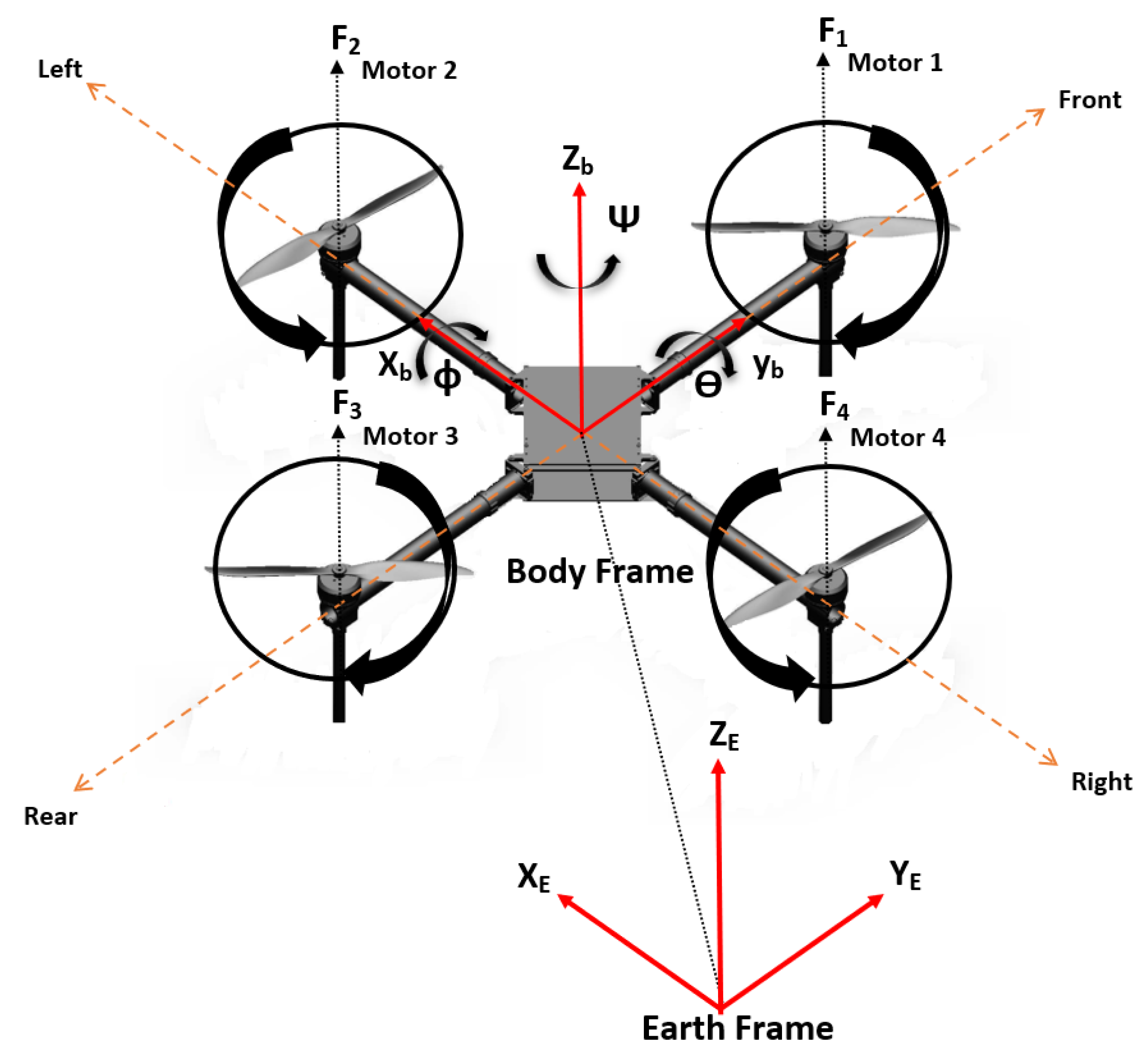
Figure 1. UAV Configuration.
Algorithms 16 00229 g001
Figure 2. (a) FTSMC algorithm displacement response compared with NTSMC control in the y axis, (b) FTSMC displacement response compared to NTSMC control in the x axis, and (c) z altitude response.
Algorithms 16 00229 g002
Figure 3. (a) Roll ( ϕ ) angle behavior using the two proposed control strategies (FTSMC vs. NTSMC), (b) Pitch ( θ ) angle behavior using the two proposed control strategies (FTSMC vs. NTSMC), and (c) behavior of the ψ angle.
Algorithms 16 00229 g003
Figure 4. (a) Behavior τ ϕ using the two proposed control strategies (FTSMC vs. NTSMC), (b) behavior τ θ using the two proposed algorithm strategies (FTSMC vs. NTSMC) and (c) behavioral response τ ψ .
Algorithms 16 00229 g004
Figure 5. Control input behavioral response ( u ) for both FTSMC and NTSMC controllers.
Algorithms 16 00229 g005
Table 1. Simulation parameters and initial conditions.
GainValueGainValueI. C.ValuePerturbationValue
FTSMC NTSMC
k z 1 1 η y 1 y 0 1 [ m ] Γ y sin 45 t [ rad / s ]
k z 2 1 q y 1 y ˙ 0 0.1 [ m / s ] Γ x sin 40 t [ rad / s ]
k y 1 p y 2 x 0 1 [ m ] Γ z sin 30 t [ rad / s ]
k x 1 η x 1 x ˙ 0 0.1 [ m / s ] Γ ϕ sin 35 t [ rad / s ]
k ψ 1 q x 1 z 0 0.1 [ m ] Γ θ sin 30 t [ rad / s ]
k 1 x 2.5 p x 2 z ˙ 0 0.1 [ m / s ] Γ ψ sin 45 t [ rad / s ]
k 2 x 1 η ϕ 1 ϕ 0 0.1 [ rad ] z d 4
k 3 x 1 q ϕ 1 ϕ ˙ 0 0 [ rad / s ] x d 6
k 4 x 1 p ϕ 2 θ 0 0.1 [ rad ] y d 6
k 1 y 2.5 η θ 1 θ ˙ 0 0 [ rad / s ]
k 2 y 1 q θ 1 ψ 0 0.1 [ rad ]
k 3 y 1 p ϕ 2 ψ ˙ 0 0 [ rad / s ]
k 4 y 1 l g y sin 45 t [ rad / s ]
α x 1.5 l g x sin 40 t [ rad / s ]
γ x 0.5 l g ϕ sin 35 t [ rad / s ]
α y 1.5 l g θ sin 30 t [ rad / s ]
γ y 0.5
β y 0.35
β x 0.5
Disclaimer/Publisher’s Note: The statements, opinions and data contained in all publications are solely those of the individual author(s) and contributor(s) and not of MDPI and/or the editor(s). MDPI and/or the editor(s) disclaim responsibility for any injury to people or property resulting from any ideas, methods, instructions or products referred to in the content.