Article

Vision-Based Concrete-Crack Detection on Railway Sleepers Using Dense U-Net Model

by
Md. Al-Masrur Khan
1,
Seong-Hoon Kee
1,* and
Abdullah-Al Nahid
2
1
Department of ICT Integrated Ocean Smart Cities Engineering, Dong-A University, Busan 49315, Republic of Korea
2
Electronics and Communication Engineering Discipline, Khulna University, Khulna 9208, Bangladesh
*
Author to whom correspondence should be addressed.
Algorithms 2023, 16(12), 568; https://doi.org/10.3390/a16120568
Submission received: 28 November 2023 / Revised: 13 December 2023 / Accepted: 14 December 2023 / Published: 15 December 2023
(This article belongs to the Topic Lightweight Deep Neural Networks for Video Analytics)

Abstract

:
Crack inspection in railway sleepers is crucial for ensuring rail safety and avoiding deadly accidents. Traditional methods for detecting cracks on railway sleepers are very time-consuming and lack efficiency. Therefore, nowadays, researchers are paying attention to vision-based algorithms, especially Deep Learning algorithms. In this work, we adopted the U-net for the first time for detecting cracks on a railway sleeper and proposed a modified U-net architecture named Dense U-net for segmenting the cracks. In the Dense U-net structure, we established several short connections between the encoder and decoder blocks, which enabled the architecture to obtain better pixel information flow. Thus, the model extracted the necessary information in more detail to predict the cracks. We collected images from railway sleepers, processed them in a dataset, and finally trained the model with the images. The model achieved an overall F1-score, precision, Recall, and IoU of 86.5%, 88.53%, 84.63%, and 76.31%, respectively. We compared our suggested model with the original U-net, and the results demonstrate that our model performed better than the U-net in both quantitative and qualitative results. Moreover, we considered the necessity of crack severity analysis and measured a few parameters of the cracks. The engineers must know the severity of the cracks to have an idea about the most severe locations and take the necessary steps to repair the badly affected sleepers.

1. Introduction

In South Korea traveling by train is one of the most convenient modes of transportation. A study showed that the railroads in South Korea cover a length of 3688 Km. A railroad commonly consists of steel rail, ballast bed, railway sleeper, railway fastener, and other parts of a railway track. Among all the components, the sleeper is a crucial component of a railway track. The principal roles of a railway sleeper include distributing loads of the trains from the steel rails to the ballast bed, reducing track movement, and stabilizing the track gauge during train travel, all of which assure safe travel for the train passengers. Timber sleepers, concrete sleepers, and to a lesser extent, steel sleepers reinforce polymeric sleepers that are commonly used on railway tracks. However, literature shows that concrete sleepers are mostly used (60–80%) for several advantages in a railway network [1]. These concrete sleepers can be damaged in the form of cracks due to rain erosion, exposure to the sun, the reaction of salts in the earth with concrete sleepers, long-term navigation, an overload of trains, and so on. These cracks can introduce dangerous situations and can cause deadly accidents based on the daily loads of traffic and the severity of the cracks. So, detecting cracks early is crucial for inspecting and assessing the usability of concrete sleepers. Over the years, manual inspection has been a common and traditional method to detect cracks in railway sleepers. However, physical assessment has blind spots, and it lacks accuracy. Furthermore, this approach is time-consuming, labor-intensive, and costly. Inspectors rely solely on their human vision while traversing railway tracks to detect cracks. Besides these, the inspection performance can be varied from time to time based on the experience level of the inspector. Replacing the manual inspection with vision-based technologies can overcome these problems, and the sleeper cracks can be detected effectively. Recently, many advances have been made in the computer vision field. And, the image-based techniques have already shown mesmerizing performance in other concrete structures like concrete pavement [2], buildings [3], tunnels [4], concrete bridges [5], etc. The image processing techniques make the concrete crack detection task fast and accurate. Therefore, utilizing the image processing methods will ensure automated sleeper crack detection and alleviate the personnel’s tedious and repetitive tasks. There are primarily two types of processing methods. The first method is to extract the features, remove the noises, and then implement classification. The image features are extracted by different types of feature extraction methods like wavelet transformation [6], Percolation methods [7], Otsu’s method [8], the morphological approach [9], etc. After extracting the features, classification algorithms are employed to classify the cracks in the images. Traditional image processing methods need to select the most relevant feature extraction approach. Even though numerous image feature extraction methods exist, there is no global feature extraction strategy to cope with images in various situations. As a result, a significant series of experiments or even novel feature extraction feature techniques must be devised to identify a suitable feature extraction approach for a specific situation. However, these methods fail to deal with images having complex patterns, extreme noises, and intensity inhomogeneity.
The other approach to image processing is utilizing the Deep Learning (DL) technology, especially the Convolutional Neural Network (CNN). CNN utilizes many hidden Neural Network (NN) layers to extract the underlying features automatically and classify the images. With the development of the AlexNet [10] using CNN in 2012, the advancement curve observed a huge surge in the field of computer vision. Following this, other CNN models with various depths have been designed. The classification was further increased in 2014 by using the newly developed VGG [11], and GoogleNet [12] model. Understanding the advancement of the CNN model and considering the necessity of monitoring the cracks in concrete structures, including railway sleepers, researchers nowadays are more inclined to utilize CNN models for detecting cracks. Zhang et al. proposed a Convolutional Neural Network (CNN) classifier in 2016 for detecting cracks in concrete structures [13]. The main aim of this research was to design a classifier based on patches for detecting cracks in concrete structures. After that, many other CNN models have been designed for solving crack image classification, detection, and segmentation tasks. Among the three types of solutions, crack segmentation has become the most popular research. Crack segmentation provides pixel-wise classification, where each of the pixels are classified as cracks or non-cracks. The predicted image from the CNN-based segmentation model highlights the cracks on the image and provides an idea about the cracks’ location and geometric shape. Furthermore, the segmented pictures can be utilized to extract a few key pieces of information (such as crack length, width, and area) that can estimate the severity of cracks in concrete sleepers. Though there are already many developed DL models, and though past research on utilizing CNNS to detect concrete cracks has generated significant results, only a few research studies have been conducted for segmenting cracks on railway sleepers using the CNNS. Despite a little research, there is still room to develop new methods to achieve higher accuracy and contribute to railway sleeper crack detection. So, in this paper, we utilize a CNN to develop a Dense U-net model by modifying the original U-net architecture to detect cracks on the railway sleeper images. Moreover, we design an algorithm for quantifying the cracks. This research study primarily offers the following contributions
  • Collecting railway sleeper images and processing them in the form of a dataset.
  • Proposing a modified U-net model for the first time to detect cracks on railway sleepers.
  • Quantifying the cracks of railway sleepers for knowing the severity of the cracks.
The rest of this study is structured as follows: The existing crack detection techniques are briefly discussed in Section 2. Section 3 offers a summary of the methodology employed in this study. Section 4 shows as well as discusses the experimental process and assessment outcomes concerning crack detection on railway sleepers. Lastly, Section 5 concludes the paper.

2. Related Work

2.1. Vision Based Crack Detection Methods

Many vision-based crack identification methods have already been suggested for solving the problem of manual inspection in the case of detecting cracks in concrete structures. One type of Computer Vision (CV)-based technique is the use of some traditional approaches. For example, Qu et al. utilized a percolation-based image processing approach to identify cracks in concrete. The authors first extracted the cracks using the genetic programming method. Later, after calculating the crack tip, they used the high-precision percolation method to detect small cracks [7]. Hoang et al. proposed a Min–Max Gray Level Discrimination (M2GLD) method to integrate with the Otsu method for detecting cracks in building structures. Their model also could find out a few crack characteristics, e.g., width, area, parameter [14]. Fujita et al. considered crack detection on noisy concrete structures. The authors used the subtraction pre-processing method for removing noises like shades and bad illumination conditions and introduced the Hessian matrix for differentiating the concrete cracks from the background [15]. Hutchison et al. presented a hybrid method based on the FHT algorithm and Canny edge detector for detecting cracks in concrete structures. The authors also calculated the parameters of the predicted cracks [16].
However, the primary limitation of these classical IPTs is that the techniques pay more attention to extracting local features rather than global properties like cracks on an image, which may downgrade the detection task. So, to improve the crack detection task, researchers started combining classification methods with the classical IPTs. As a consequence, Jahanshahi et al. developed a unique approach based on morphological operations and classifier techniques. The morphological operator was used to extract the necessary features, and the classifier algorithms classified real cracks [17]. Shi et al. presented a new framework named Crack-Forest based on Random Structured Forest for detecting cracks as well as characterizing the cracks on concrete roads [18]. Chun et al. presented a hybrid crack detection framework by combining a canny edge detector for extracting geometric features of the cracks and a supervised ML algorithm named Light Gradient Boosting Machine (LightGBM). The authors evaluated their framework by using photos containing cracks with adverse conditions [19].
In recent years, Deep Learning (DL) models have outperformed classical CV-based techniques for detecting objects. Furthermore, DL models do not need external feature learning; they can perceive features from a significant quantity of input data. Therefore, researchers are paying attention to detecting concrete cracks with more precision using DL algorithms. Cha et al. introduced a Convolutional Neural Network (CNN) classifier and a sliding window technique for detecting cracks in concrete structures. The authors tested the robustness of their model by predicting external images and showed that their model outperformed the Sobel and Canny edge detection method [20]. Xu et al. presented a DL model by using a Restricted Boltzmann Machine (RBM) algorithm to detect cracks on bridge structures. The authors trained their model with consumer-grade camera images and used a divergence learning algorithm to obtain optimal parameters [21]. Chen et al. introduced a novel DL framework named NB-CNN by fusing Naive Bayes data with a CNN classifier for extracting cracks on a nuclear power plant from video frames. Their method could maintain the spatiotemporal video coherence and produce better results than LBP-SVM [22]. Maeda et al. presented a benchmark road crack dataset for the first time using smartphone images and used a CNN to classify eight types of cracks on road surfaces [23]. Zhang et al. focused on both improving crack detection accuracy and reducing the training time of the Deep Learning model. As a consequence, they developed a Deep Learning model named MobileNetV3-BLS based on MobileNetV3 to detect cracks on concrete surfaces. The authors also claimed that the weights of their method can be updated quickly, which helps to obtain increased accuracy with newly added nodes [24]. Nguyen et al. proposed a Deep Learning classifier to detect concrete cracks. The authors utilized a genetic algorithm to optimize the parameters of the image processing technique [25]. Katsigiannis et al. created a dataset of brickwork masonry facades and built a Deep Learning model using the transfer learning strategy to detect cracks on the masonry facades using their limited data [26]. Deng et al. proposed the You Only Look Once (YOLO) version 2 model for locating cracks with bounding boxes on concrete structures. The model was able to distinguish cracks from handwritten scripts present in the concrete structure [27]. Hyuan et al. presented a method called Crack Deep Network (CrackDN) based on Faster Region CNN (Fast RCNN) to identify sealed and unsealed cracks having diverse backgrounds in pavement images. The authors extracted features by a Zeiler-Fragus Network (ZF-Net)-based CNN embedded with a sensitivity network in parallel. Finally, they utilized a Region proposal Refinement Network (RPRN) for classifying the cracks [28]. Jian et al. proposed a modified YOLO-V5 network by adding a swin transformer and a bidirectional feature pyramid. The authors claimed that they obtained better performance than the YOLO-V7 model [29]. Chen et al. considered the problem of variable illumination conditions in the case of crack detection in their work [30]. To solve the issue, the authors proposed a model named IlumiCrack, which uses a Gaussian model to play with the brightness of pictures and an SGD model to detect the cracks. However, these models are capable of categorizing and localizing cracks within a concrete structure, but they cannot detect cracks at the individual pixel level.
Therefore, among the DL models nowadays, encoder–decoder-based pixel-level crack detection models (i.e., FCN [31], U-net [32]) are becoming more popular for improving the detection accuracy as these models can extract the geometrical shape of the cracks along with localizing them. Li et al. proposed a novel encoder–decoder-based model called an FCN for detecting cracks where the VGG19 model was used as the downsampler of the proposed FCN. After predicting the crack images, the authors also generated crack skeletons to measure morphological features [33]. Bang et al. proposed an FCN model based on the ResNet-152 encoder network for detecting pavement cracks from black-box camera images. The authors examined their model with transfer learning and without the transfer learning processes. However, Resnet-152 with transfer learning performed better [34]. Manjurul et al. proposed an FCN model using the VGG16 as an encoder network to detect cracks on concrete surfaces. The authors tested their model on a benchmark dataset and showed that their model obtained a 10.93% and 20.93% improvement over the CNN and SVM model, respectively, with respect to the SA [35]. Liu et al. adopted U-net, which is another encoder–decoder-based network (the improved version of FCN), to segment cracks in concrete structures. The authors introduced the focal loss function for handling the class imbalance problem in their work [36]. Ji et al. also utilized the U-net model with zero paddings in their work for automatically detecting cracks in concrete structures. They trained the model using 200 images collected by an unmanned aerial vehicle and obtained better results than the Canny and Sobel method [37].
However, U-net models can also fall behind in predicting extremely narrow cracks and detecting cracks in adverse conditions. So, nowadays, researchers are continuously integrating different approaches with U-net to address these challenges. Yan et al. proposed a model called Res-Unet by incorporating residual connections to the original U-net for detecting cracks in the concrete bridge structures [38]. Chen et al. integrated a switch module named SWM with the U-net architecture to boost the running speed and reduce the computational complexity of the U-net. The SWM model allows the pixel classification result obtained by the VGG13 encoder to be passed into the decode module if there is a crack; otherwise, it just discards the result to save the computation time [39]. Sun et al. considered the problem of detecting thin cracks with adverse environmental conditions in concrete structures. For this, the authors modified the U-net architecture by adding a Pyramid Pooling Module (PPM) into it, and the model successfully predicted the thin cracks [40]. Lin et al. proposed a U-net model with an attention mechanism to detect cracks on concrete structures. The authors utilized the attention gate module in three different fashions (i.e., Attention U-net, Advanced Attention U-net, and Full Attention U-net). They remarked that the full attention strategy was the best for detecting cracks with less computation complexity [41]. Augustauskas et al. improved the U-net model by adding residual blocks, an atrous spatial pyramid pooling module, and an attention gate module for detecting concrete cracks. The authors tested their model with a few datasets and showed by an ablation study that the improved model outperformed U-net with no notable computational complexity [42]. With the period, researchers have developed other encoder–decoder-based architectures as well, rather than improving the U-net. For example, Li et al. proposed a model named HrSegNet to improve the inference speed of crack segmentation while preserving the crack details [43]. Wang et al. tackled the challenge of high computation complexity during the training of a crack segmentation network in their work [44]. The authors developed their model based on a student–teacher framework. They utilized channel-wise distillation knowledge to make the model lightweight. Yang et al. developed a model named PAF-Net by incorporating a feature fusion technique to mitigate semantic gap issues during crack segmentation in concrete structures [45]. Khan et al. proposed a segmentation model named RCDNet to detect cracks on pavement structures in real-time [46]. The authors incorporated attention modules to increase the accuracy of the model without any computational head.

2.2. Crack Detection on Railway Sleepers
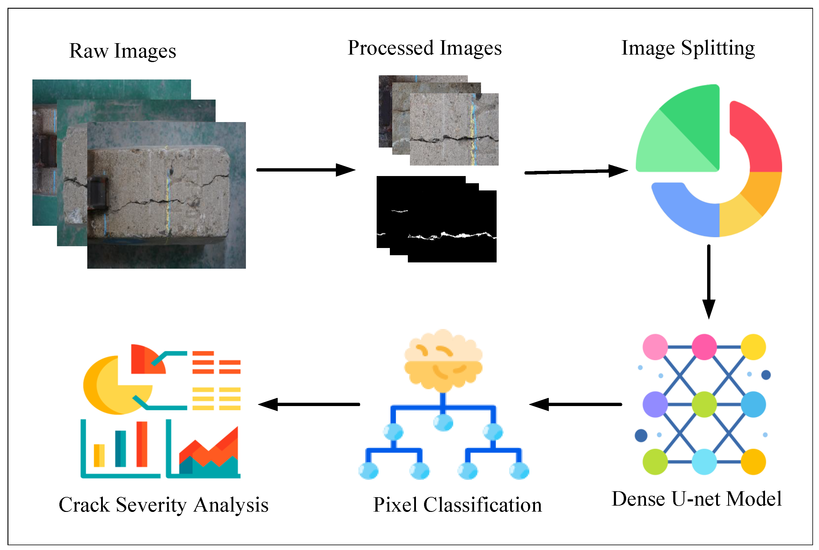
Though there are many research works for detecting cracks on various concrete structures, there are not many equivalent works to detect cracks on railway sleepers. Rather, vision-based techniques are employed to a lower extent for solving some other similar types of problems in railway industries. For example, Saha et al. detected cracks on railway tracks using a vision-based technique by including edge detection methodology [47]. Fan et al. presented a method by combining local binary features and an SVM classifier for detecting defective fasteners in railway tracks [48]. Mehmet et al. employed a method based on a canny edge extractor and hough transformation to monitor the condition of the railway components [49].
Crack monitoring in rail tracks can be viewed from various perspectives, each with its own set of objectives. Thendral et al. presented a machine vision system for detecting cracks on railway tracks. The authors first extracted the features using the Gabor transform and passed those features to a neural network classifier. They achieved an overall accuracy of 94.9% during detecting the cracks [50]. Min et al. detected cracks on railway tracks using two steps. First, the authors found the tracks using the features of the hue channel, and later, they performed contour-based surface profiling to classify the defects [51]. Sajjad et al. detected cracks not only on wooden sleepers, but also on concrete sleepers by utilizing a vision-based technique. However, as the authors developed the system based on a binary thresholding technique, it may lose robustness during environmental and illumination changes [52]. Delfourazi et al. proposed a crack detection method for railway sleepers using the template matching technique first to detect the concrete sleepers. Then, they used linear SVM and Radial-basis Function SVM (RBF-SVM) to classify the crack types on the sleepers. Numerical results showed that RBF-SV performed better [53]. Kim et al. proposed an advanced method using the Adaboost algorithm for detecting cracks on railway sleepers. Their algorithm identified the cracks with an identification rate of more than 90% [54]. Wang et al. proposed a two-stage algorithm for detecting cracks on concrete railway sleepers with less computation time. First, they used an edge detection technique called neighborhood range algorithm for selecting crack areas and then utilized CNN on top of it to successfully classify the crack types [55]. Xia et al. presented a novel framework named CF-NET based on the RetinaNet object detection framework to detect cracks with bounding boxes on railway sleepers [56]. Jang et al. proposed a modified version of Single Shot Detector for detecting cracks on railway sleepers. The authors compared between two images and detected deformed regions to find the cracks [57].
The literature shows that already there are some remarkable DL-based research works for detecting cracks in different concrete structures. However, most crack detection systems for railway sleepers rely on traditional image processing techniques. Though there are a few CNN-based works, they cannot detect cracks at a pixel level. To the best of the authors’ knowledge, no prior research work has utilized a DL model based on encoders and decoders to identify pixel-level cracks on railway sleepers. So, for the first time, in this work, we adopt U-net and propose a modified U-net architecture named Dense U-net for detecting railway sleeper cracks at a pixel level. Moreover, we also calculate a few parameters of the cracks (e.g., length, maximum width, area, density).

3. Methodology

The method we proposed in this study includes a supervised learning technique and a few morphological operations for detecting cracks at a pixel level on railway sleepers and analyzing the geometric patterns of the cracks from RGB images. The overall methodology of this work is divided into several steps, which are illustrated in Figure 1. The description of each phase is presented in the following subsections.

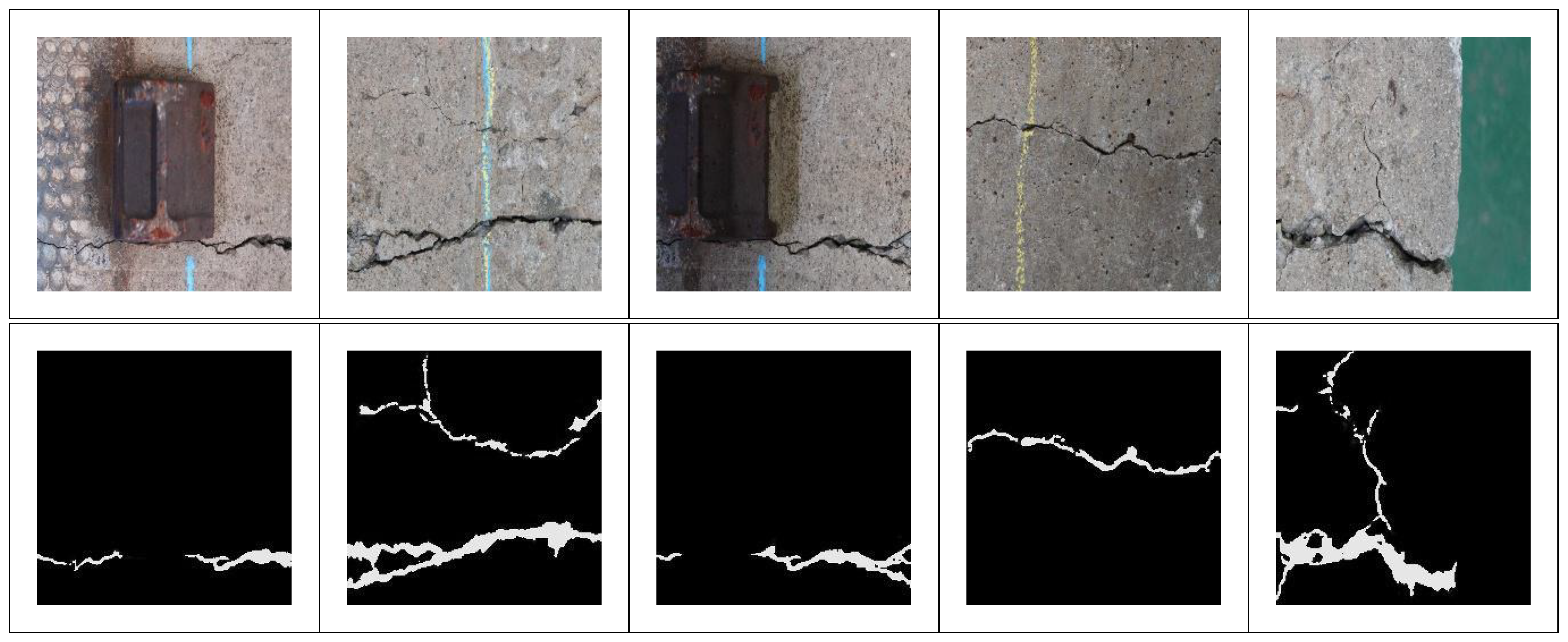
3.1. Dataset Description

The dataset we used in this study is images from a few railway sleepers collected from Busan station, South Korea. We captured 113 images with a resolution of 3500 × 2500 pixels by using a Sony a7r III mirrorless; manufactured by Sony Electronics, San Diego, CA, USA. camera. As the resolution of the images is so high, it may increase the computational complexity, so we could not use the high-resolution images directly in the Deep Learning model. Furthermore, it was also not convenient to resize the images into some smaller resolutions because of the need to maintain the image quality. To overcome this issue, we split each image into nine different parts and got 1017 images. For splitting the images into nine different parts, we first divided the image into three different rows and three different columns. As a result, we obtained 9 different 3 × 3 grids from one single image. After that, we collected the coordinates of those grids and cropped the images based on the grids. As we split the images by dividing them into independent grids based on the coordinates, it helped us to generate non-overlapping image patches from one single image. However, some images among these 1017 images do not contain sleepers. Instead, they contain the lab floor, bucket, and other noises. So, we eliminated those images, and finally, our dataset included 660 images. Later we manually annotated our dataset for the segmentation task. Examples of a few images (original and the mask) of our utilized dataset are displayed in Figure 2.

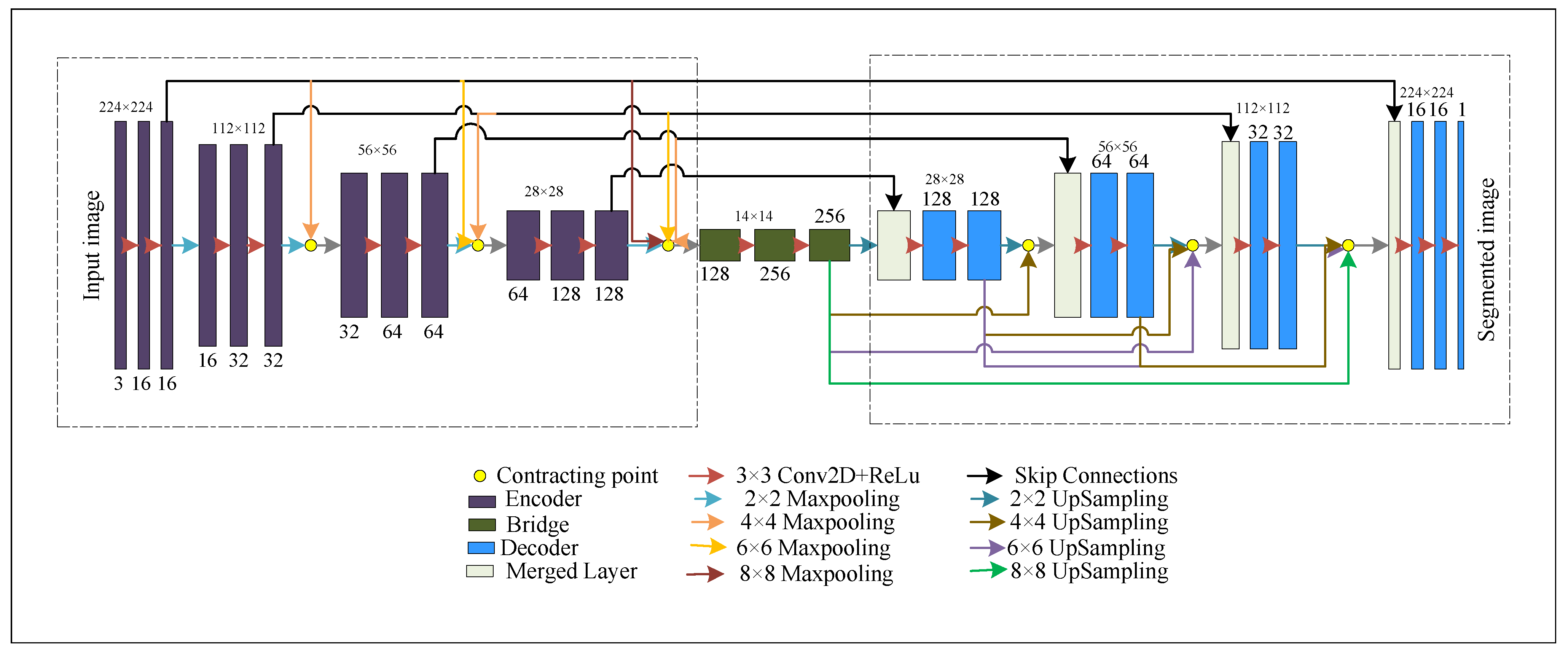
3.2. Model Architecture

This paper designed a railway sleeper crack detection system based on Ronneberger’s U-net architecture. U-net is a classic encoder–decoder [59] model where the encoder part extracts necessary features of the images, and the decoder part of the model generates predicted images (exact resolution with input image) by combining the features extracted from the encoder module. Unlike the FCN model, U-net architecture uses skip connections for maximum information flow from the encoder to the decoder module. To improve the result of the original U-net model, in this study, we proposed a Dense U-net model by combining the concept of both U-net and DenseNet [60] architectures. The architecture of the proposed Dense U-Net method is illustrated in Figure 3.
The encoder module’s structure is shown in the left dotted box. The encoder module consists of a total of 4 encoder blocks. Each of the encoder blocks consists of two repeated convolution layers for extracting the features, followed by an activation function layer. We used a kernel size of 3 × 3, the same padding, and the Rectified Linear Unit (ReLu) activation function throughout the architecture.
The convolution kernels traverse through the images and perform element-wise multiplication with the corresponding elements of the receptive fields. The mathematical equation of the convolution operation is as follows:
F ( p , q ) = ( A B ) ( p , q ) = c d A ( c , d ) B ( p c , q d )
where A is the input image, B is the filter, p, q denotes the rows, and the columns of the image, c, and d are loop controllers. After stacking the outputs from all of the kernels, the feature map function from a particular layer l can be achieved, which can be stated as follows:
v l = f ( b l + W l z l r 1 )
f ( z ) = R e L u ( z ) = z , if z > 0 0 , o t h e r w i s e
where v is the extracted feature, b denotes the bias vector, W denotes the weight matrix, and z is the input from the previous layer. The utilized ReLu activation function converts the output values to z if z is a positive number, otherwise, the output is 0. The dimension of the extracted features can be calculated by utilizing the equation below:
( M , N , N c ) × ( f , f , f c ) = ( [ ( A + 2 p f ) / S + 1 ] )
where S = number of stride, p = number of padding, N c = number of channels, f c = number of filters, A is input image, f = size of the kernel. Finally, at the end of each encoder block, we used a 2 × 2 Maxpooling layer to reduce the spatial dimensions of the feature maps to one-quarter in size. If a feature map has a dimension of N × 1, then the Maxpooling will be
o j = m a x N × 1 { o i n × 1 d ( n , 1 ) }
where, d ( n , 1 ) is a window patch from the N × 1 dimensional feature map and o j is the maximum value among the considered patch.
As the DenseNet model argued that short connections among the layers of a DL network improve the feature propagation, we established a few short linkages among the encoder layers and the original contracting path. We designed the short connections in such a way so that an encoder block, as well as the bridge between the encoder and decoder module, can get the features produced by all of the previous encoder layers directly through the short connections. Mathematically, the eth encoder layer E e is receiving the features of all the previous encoder layers, v E 0 , v E 1 , …… v E e 1 , as input:
v E e = C ( [ v E 0 , v E 1 , v E e 1 ] )
where C denotes the concatenation of all the features from E 0 , E 1 , … E e 1 encoder layers. Before concatenation, we reshape the features from different encoder blocks in a particular spatial size using max pooling of different levels (see Figure 3). We reshape the features of different encoder blocks using multi-kernel max pooling (e.g., 2 × 2, 4 × 4, 6 × 6, 8 × 8), i.e., using multiple receptive fields. We obtain several sub-feature maps from the encoder blocks and capturing pixel information from multi-scale local ranges. As a result, while passing fine-grained low-level information to the proceeding encoder layers, a scale-invariant model is also being developed to share more pixel information. Moreover, the model can share information from multiple scales and increase the architecture’s robustness to extract essential redundant features for detecting cracks of different sizes.
The decoder module’s structure is shown in the right dotted box. The decoder module also consists of 4 decoder blocks. Each block in the decoder consists of a merged layer (see paste colored block in Figure 3), and then the structure contains two repeated 3 × 3 convolution blocks like the encoder. The merged layer includes two inputs: one is the feature map from the corresponding encoder layer (black arrow in Figure 3), and the other one is the concatenation (yellow circle in Figure 3) of the outputs of the previous encoder blocks. The merged layer also includes a bridge as we also construct the short linkages in the decoder module. Before concatenating, we upsampled the features from different blocks in the same spatial size. For example, the merged layer of the last block of the decoder module receives the feature map from the first encoder block, whose shape is 224 × 224 × 16. So, the other input must be in the same shape. We upsampled the feature maps from all of the previous decoder blocks whose initial shapes were 14 × 14 × 256, 28 × 28 × 128, 56 × 56 × 64, 112 × 112 × 32 and converted them in the shape of 224 × 224 × 16 by using different upsampling levels. After getting the same size, we concatenated them and provided them as the second input of the merged layer. In this strategy, the decoder blocks are not only considering the feature maps of the corresponding encoder blocks, but also using the feature maps of all the previous decoder blocks and the bridge. As a result, a better flow of pixel reconstruction has been established, and the U-net model has become more efficient. Finally, a 1 × 1 convolution was utilized to categorize the “Crack” and the “Non-crack” pixels at the last layer.

3.3. Loss Function and Hyperparameters

In this work, we have deployed the dice loss function. The formula to calculate the dice loss function is as follows:
D i c e L o s s = 1 2 i m i n i + γ m i 2 + n i 2 + γ
where m represents the predicted probabilities of the classes, n denotes the ground truth data, and  γ denotes the smoothing factor. In this paper, we divided the dataset into 7:3 for training and testing the model and resized input images and ground truths in the size of (224 × 224 × 3) and (224 × 224 × 1), respectively. We chose the Adam optimizer for optimizing our model. We set the batch size at 8, the learning rate at 0.0001, and trained the model to 100th epochs.

3.4. Crack Severity Analysis

The Dense U-net model segments cracks within images, but assessing the severity requires determining crack count and various morphological traits. To accomplish this, we employed a traditional image processing method outlined as follows.

3.4.1. Counting the Cracks

In the initial phase of our crack severity analysis, we determined the number of individual cracks within the railway sleeper images. This count was achieved by employing contour detection, a method that identifies closed curves with consistent pixel intensities, outlining the boundaries, and connecting continuous points within the images. Let an image as 2D function f ( x , y ) then,
f ( x , y ) = c
where c is the constant pixel value. So, through the contour detection process, we are identifying the connected regions of predicted crack pixels from the Dense U-net model, outlining the crack boundaries. This method enables the calculation of the number of detected contours, essentially representing the count of individual crack objects within the images.

3.4.2. Extracting Morphological Features

Following the extraction of individual crack objects in the prior step, we proceeded to compute the morphological characteristics of the cracks, including length, width, area, and density. To derive the length and maximum width of the cracks, we implemented Algorithm 1. From the previous section, we have the boundaries of the contours, i.e., cracks. Let a contour C = [X, Y], which is an array of two columns and N rows (i.e., length of the contour) and where x 0 , x 1 , …… x n ∈ X denotes the rows of the image and y 0 , y 1 , …… y n ∈ Y denotes the columns of the image. Let ( x 0 , y 0 ) and ( x n , y n ) are the starting point and the ending point of the contour i.e., crack respectively. To find out the length of the crack, we have calculated the distance between the starting point and the ending point of the crack boundary using the distance formula. Then, for calculating the maximum width of a crack, we have traversed from the starting column y 0 to the ending column y n of the crack boundary. During this crossing, we have found out and stored the rows where any particular column y j has traveled in a list named occurs. We estimated the number of rows traveled by any column y j when this searching loop was completed, and we appended the results for each column to a list entitled widths. Finally, we have searched for the maximum value in the list, and thus, we have calculated the maximum width of a crack.
Algorithm 1: Algorithm for length and width calculation.
Algorithms 16 00568 i001
We determined the area of the contours, representing the area of individual cracks. By summing the areas of these individual cracks, we obtained the total area covered by cracks within an image. This total area was then divided by the number of pixels, yielding the density of the cracks present in the image.

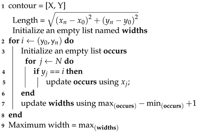
4. Results and Discussions

In this study, we implemented our proposed neural network model in a Python programming language using the Deep Learning framework of Keras. We trained the model and conducted our experiments in a computer configured with a Windows 10 operating system, 32 GB RAM, Intel core i9-11900k @ 3.50 GHz CPU processor, and NVIDIA Geforce RTX 3080Ti graphics card.
To evaluate the performance of our proposed model, the segmentation effect of the railway sleeper images was tested. Both the original U-net model and the improved Dense U-net model were examined on the same test set to compare their effectiveness. The quantitative and qualitative results are discussed in the following sections.

4.1. Quantitative Results

In this section, we present the quantitative results achieved by our proposed Dense U-net model. For verifying the performance of our proposed model, we calculated Accuracy, Recall, Precision, F1-score, IoU as the assessment metrics by using the following equations.
A c c u r a c y = T P + T N T P + T N + F P + F N
P r e c i s i o n = T P T P + F P
R e c a l l = T P T P + F N
F 1 - s c o r e = 2 × P r e c i s i o n × R e c a l l P r e c i s i o n + R e c a l l
I o U = T P T P + F P + F N
where, TP, TN, FP, and FN denote the number of true positives, true negatives, false positives, and false negatives respectively. Table 1 presents the test results of both the U-net and the Dense U-net model. We can see from Table 1 that the segmentation result of the Dense U-net model is better than the result of the original U-net model. Though the Precision value of the Dense U-net model is 0.9% lower than the U-net model, the Recall value is increased by 4.7%; hence, the overall F1-score (an important evaluation metric for segmentation task) is also increased by 2.15%. In this work, we considered one more important metric, IoU, which increased by 3.28% in the Dense U-net model. Thus, the experimental results show that our proposed Dense U-net model is more effective than the original U-net model in the case of segmenting the railway sleeper images.

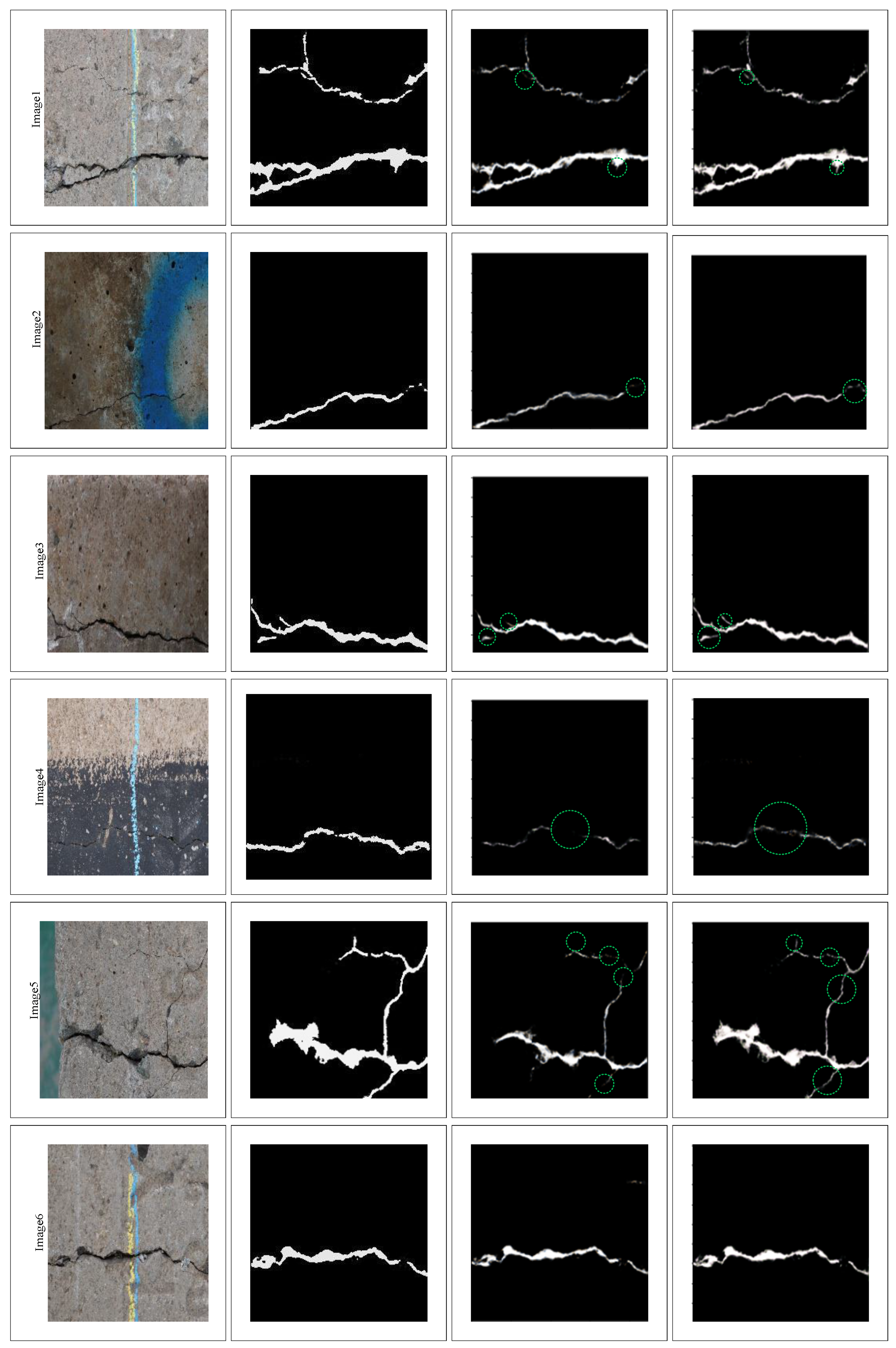
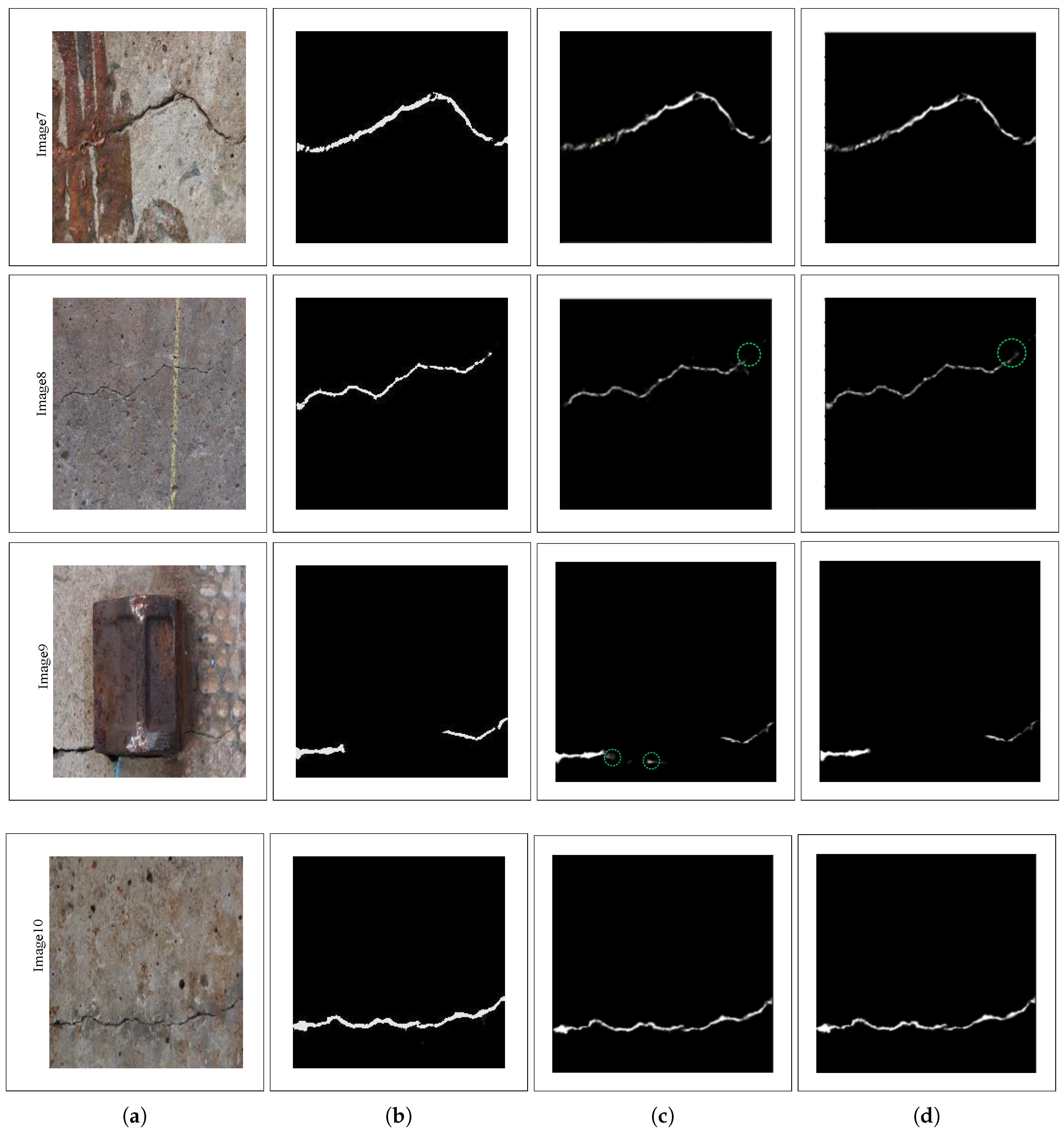
4.2. Qualitative Results

In this subsection, we present the qualitative analysis of some representative images from the test set, as demonstrated in Figure 4. The first column of Figure 4 displays the actual railway sleeper images; the second column displays the corresponding ground truth images; and the last two columns display the segmented results by the U-net model and the Dense U-net model, respectively.
To understand the detailed segmentation performance of the model more clearly, some portions of the images are highlighted by a green circle. We can see that both the original U-net model and the Dense U-net model predict the cracks on the railway sleeper images quite well. However, if we go for a detailed inspection, in the first, second, third, and eighth images, some tiny cracks are detected by a lesser intensity of the pixels. In contrast, the Dense U-net model predicted higher pixel intensity in more detail. In the case of the fourth image, the U-net model could not predict a more significant portion of the tiny cracks when the railway sleeper is black-colored; in contrast, the Dense U-net model predicted more effectively even in a noisy environment. From the fifth picture, it can be viewed that the original U-net model missed multiple narrow portions of the cracks, but the modified U-net model predicted them well. Both of the models were segmented accurately from the sixth, seventh, and tenth images. In the case of the ninth image, the original U-net model mistakenly predicted a non-crack portion as a crack, but the Dense U-net model avoided that portion efficiently. These experimental results show that our proposed Dense U-net model is more accurate than the conventional U-net model for predicting the cracks on the railway sleeper images.

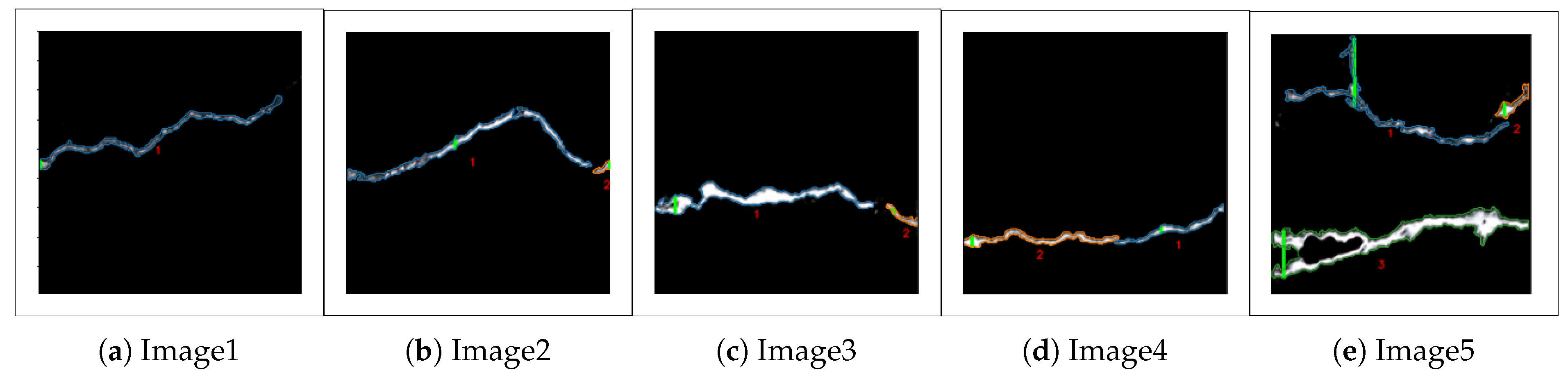
4.3. Crack Measurement Results

In the previous section, we provided the visualization of the segmented cracks by both of the models. We found that the Dense U-net model can detect cracks in more detail. So, we consider the output of the Dense U-net model for finding the number of cracks and the morphological features of the individual cracks in an image. Figure 5 shows a few images in which the individual crack boundaries are designated with different colors; the locations of the cracks that contain the maximum widths are highlighted by a green line, and the cracks are labeled by one specific number.
Figure 5 displays the first image containing only one crack; each of the second, third, and fourth images contain two different cracks; and finally, the fifth picture contains three different cracks. After finding the number of cracks, we have also calculated the length, maximum width, and area of the individual cracks by following the approach presented in Section 3.4.2. We have also determined the entire area of the cracks and the crack density so that we can have a better idea about the severity of cracks in a particular image. Furthermore, we have counted the number of white image pixels to justify the determined area by the method. Table 2 Summarizes the measurement results for all the pictures in Figure 5.
From Table 2, it is evident that in the first image, the crack is the least severe. Only 1.77% of the image contains the cracks. In the second image, there are two separate cracks. One of the cracks is more prominent (208.24 pixels in length), and the other is smaller (17.20 pixels). The maximum width of the two cracks is 9 and 6 pixels, respectively, in this image. We can see that the crack area in the second image is 1288.82 pixels, and it has about 2.56% of crack density. The second, third, and fourth images also contain two separate cracks. Still, the crack density of the third image is higher (3.33%) than the other images, which contain one and two individual cracks. The maximum width of the major crack is also relatively thicker (15 pixels) in this image. In the case of the fifth image, we can see that there is a total of three individual cracks. If we notice carefully, it can be seen that there is a vast difference between the estimated total area and the sum of white pixels for this picture. The main reason behind this is the third crack of this image has a non-crack portion inside the crack boundary. As the other crack portions are continuous, our model counted it as a single crack. Still, for having a non-crack portion, the area calculated by our method has become much greater than the total number of pixels. Furthermore, the maximum width of the first and third cracks is overestimated and not estimated in the correct location. We have used the boundary positions of the cracks to calculate the maximum width. So, if a crack object has multiple horizontally parallel branches, in that case, there are multiple branches of a crack in the same column of the image, our model estimates the distance from the starting point of the first crack to the ending point of the last crack as the width of that location. However, for this image, if we consider the sum of white pixels as area, the density of the cracks becomes 10.21% which is the highest among all the sample pictures in Figure 5.

5. Discussion and Conclusions

In this research work, we presented a modified U-net network named Dense-Unet for detecting cracks on the concrete sleepers of a railroad. At this point, many DL-based methods have already been developed to detect cracks at a pixel level on different concrete structures. However, before our research, no previous research detected cracks at pixel levels on the concrete sleepers of a railroad. To modify the original U-net structure, several short connections were established between each of the encoder and decoder blocks, which extract denser and multi-scale necessary features and obtain and pass denser pixel information. Both the quantitative and qualitative results showed the proposed algorithm performed better than the conventional U-net model when predicting cracks on the concrete sleepers. The overall F1-score reached 86.56%, which was 2.15% greater than the original U-net model. Furthermore, we analyzed the severity of cracks in the predicted images by calculating the length, maximum width, area, and ratio of the cracks. Compared with the previous works in the field of crack detection in railway sleepers, the advantage of our method is it can detect the cracks at the pixel level, whereas the previous DL-based works can only detect the existence of cracks from the images. Our method can detect the existence of cracks from the images as well as localize the cracks in the image. Besides these, our method can extract the shape of the cracks in an image and detect the pixels containing the cracks, which helps find out the size of the cracks and the severity of the cracks. In short, our work advances the field from the present state of knowledge by implementing a segmentation technique rather than using classification techniques that open a window for having the idea of crack locations, crack shapes, and the severity of cracks in railway sleepers. The disadvantage of our method is the DL-based supervised model is always in need of labeled data, which is difficult and time-consuming to annotate. Moreover, during the creation of the dataset, we collected the images from an indoor environment. Our dataset does not cover the images of concrete sleepers of different locations, of different time frames, (e.g., morning, noon, evening, night), and different illumination conditions. As a consequence, our developed method may struggle during practical real-time detection. As in a real environment, there might be extreme sunshine, and dark shadow, which can vary the brightness level of the pictures, and the sleepers may have different textures. Hence, our trained model can find it difficult to detect railway sleeper cracks during practical application. So, in the future, domain-adaptive self-supervised learning techniques can be adopted to detect cracks in railway sleepers to solve the issue of annotated data as well as the problem of domain shift. One more limitation of our method for severity analysis is that if a crack object has multiple horizontally parallel branches, our model overestimates the maximum width and overlooks the maximum width location. In our future work, we plan to develop a more accurate segmentation model as well as a regression-based Deep Learning technique for detecting crack sizes, and severity without any postprocessing techniques.

Author Contributions

Conceptualization, M.A.-M.K. and S.-H.K.; methodology, M.A.-M.K., A.-A.N. and S.-H.K.; software, M.A.-M.K. and S.-H.K.; validation, S.-H.K., A.-A.N. and M.A.-M.K.; writing—original draft preparation, M.A.-M.K., S.-H.K. and A.-A.N.; writing—review and editing, S.-H.K., A.-A.N. and M.A.-M.K. All authors have read and agreed to the published version of the manuscript.

Funding

This research was supported by the Basic Science Research Program through the National Research Foundation of Korea (NRF) funded by the Ministry of Education (2016R1A6A1A03012812).

Institutional Review Board Statement

Not applicable.

Informed Consent Statement

Not applicable.

Data Availability Statement

Data are contained within the article. However, the data presented in this study are also available upon request from the corresponding author.

Acknowledgments

The works in the paper were performed at the department of ICT integrated Ocean Smart Cities Engineering at Dong-A University, Busan, South Korea when Md. Al-Masrur Khan was a master’s degree student at Dong-A University.

Conflicts of Interest

The authors declare no conflict of interest.

References

  1. International Union of Railways—The Worldwide Railway Organisation. UIC. Available online: https://uic.org/ (accessed on 14 December 2023).
  2. Tang, Y.; Zhang, A.A.; Luo, L.; Wang, G.; Yang, E. Pixel-level pavement crack segmentation with encoder-decoder network. Measurement 2021, 184, 109914. [Google Scholar] [CrossRef]
  3. Zheng, M.; Lei, Z.; Zhang, K. Intelligent detection of building cracks based on Deep Learning. Image Vis. Comput. 2020, 103, 103987. [Google Scholar] [CrossRef]
  4. Ren, Y.; Huang, J.; Hong, Z.; Lu, W.; Yin, J.; Zou, L.; Shen, X. Image-based concrete crack detection in tunnels using deep fully convolutional networks. Constr. Build. Mater. 2020, 234, 117367. [Google Scholar] [CrossRef]
  5. Fu, H.; Meng, D.; Li, W.; Wang, Y. Bridge Crack Semantic segmentation based on improved deeplabv3+. J. Mar. Sci. Eng. 2021, 9, 671. [Google Scholar] [CrossRef]
  6. Nigam, R.; Singh, S.K. Crack detection in a beam using wavelet transform and photographic measurements. Structures 2020, 25, 436–447. [Google Scholar] [CrossRef]
  7. Qu, Z.; Chen, Y.-X.; Liu, L.; Xie, Y.; Zhou, Q. The Algorithm of Concrete Surface Crack Detection Based on the Genetic Programming and Percolation Model. IEEE Access 2019, 7, 57592–57603. [Google Scholar] [CrossRef]
  8. Chen, B.; Zhang, X.; Wang, R.; Li, Z.; Deng, W. Detect concrete cracks based on Otsu algorithm with Differential Image. J. Eng. 2019, 2019, 9088–9091. [Google Scholar] [CrossRef]
  9. Hou, H.; Lin, W. A new approach for the detection of concrete cracks based on adaptive morphological filtering. In Fuzzy Systems and Data Mining VI; IOS Press: Amsterdam, The Netherlands, 2020. [Google Scholar] [CrossRef]
  10. Krizhevsky, A.; Sutskever, I.; Hinton, G.E. ImageNet classification with deep convolutional Neural Networks. Commun. ACM 2017, 60, 84–90. [Google Scholar] [CrossRef]
  11. Simonyan, K.; Zisserman, A. Very deep convolutional networks for large-scale image recognition. arXiv 2014, arXiv:1409.1556. [Google Scholar]
  12. Szegedy, C.; Liu, W.; Jia, Y.; Sermanet, P.; Reed, S.; Anguelov, D.; Erhan, D.; Vanhoucke, V.; Rabinovich, A. Going deeper with convolutions. In Proceedings of the 2015 IEEE Conference on Computer Vision and Pattern Recognition (CVPR), Boston, MA, USA, 7–12 June September 2014; pp. 1–9. [Google Scholar]
  13. Zhang, L.; Yang, F.; Zhang, Y.D.; Zhu, Y.J. Road crack detection using deep convolutional neural network. In Proceedings of the 2016 IEEE International Conference on Image Processing (ICIP), Phoenix, AZ, USA, 25–28 September 2016; pp. 3708–3712. [Google Scholar] [CrossRef]
  14. Hoang, N.-D. Detection of surface crack in building structures using image processing technique with an improved Otsu method for image thresholding. Adv. Civ. Eng. 2018, 2018, 3924120. [Google Scholar] [CrossRef]
  15. Fujita, Y.; Hamamoto, Y. A robust automatic crack detection method from noisy concrete surfaces. Mach. Vis. Appl. 2010, 22, 245–254. [Google Scholar] [CrossRef]
  16. Hutchinson, T.C.; Chen, Z.Q. Improved image analysis for evaluating concrete damage. J. Comput. Civ. Eng. 2006, 20, 210–216. [Google Scholar] [CrossRef]
  17. Jahanshahi, M.R.; Masri, S.F.; Padgett, C.W.; Sukhatme, G.S. An innovative methodology for detection and quantification of cracks through incorporation of depth perception. Mach. Vis. Appl. 2011, 24, 227–241. [Google Scholar] [CrossRef]
  18. Shi, Y.; Cui, L.; Qi, Z.; Meng, F.; Chen, Z. Automatic Road Crack Detection Using Random Structured Forests. IEEE Trans. Intell. Transp. Syst. 2016, 17, 3434–3445. [Google Scholar] [CrossRef]
  19. Chun, P.; Izumi, S.; Yamane, T. Automatic detection method of cracks from concrete surface imagery using two-step light gradient boosting machine. Comput.-Aided Civ. Infrastruct. Eng. 2020, 36, 61–72. [Google Scholar] [CrossRef]
  20. Cha, Y.-J.; Choi, W.; Büyüköztürk, O. Deep learning-based crack damage detection using convolutional neural networks. Comput.-Aided Civ. Infrastruct. Eng. 2017, 32, 361–378. [Google Scholar] [CrossRef]
  21. Xu, Y.; Li, S.; Zhang, D.; Jin, Y.; Zhang, F.; Li, N.; Li, H. Identification framework for cracks on a steel structure surface by a restricted boltzmann machines algorithm based on consumer-grade camera images. Struct. Control. Health Monit. 2017, 25, e2075. [Google Scholar] [CrossRef]
  22. Chen, F.-C.; Jahanshahi, M.R. NB-CNN: Deep Learning-Based Crack Detection Using Convolutional Neural Network and Naïve Bayes Data Fusion. IEEE Trans. Ind. Electron. 2018, 65, 4392–4400. [Google Scholar] [CrossRef]
  23. Maeda, H.; Sekimoto, Y.; Seto, T.; Kashiyama, T.; Omata, H. Road Damage Detection and Classification Using Deep Neural Networks with Smartphone Images. Comput.-Aided Civ. Infrastruct. Eng. 2018, 33, 1127–1141. [Google Scholar] [CrossRef]
  24. Zhang, J.; Cai, Y.Y.; Yang, D.; Yuan, Y.; He, W.Y.; Wang, Y.J. Mobilenetv3-BLS: A broad learning approach for automatic concrete surface crack detection. Constr. Build. Mater. 2023, 392, 131941. [Google Scholar] [CrossRef]
  25. Nguyen, C.K.; Kawamura, K.; Nakamura, H. Deep learning-based crack detection and classification for Concrete Structures Inspection. In Proceedings of the 17th East Asian-Pacific Conference on Structural Engineering and Construction, Singapore, 27–30 June 2022; Lecture Notes in Civil Engineering. Springer: Singapore, 2023; pp. 710–717. [Google Scholar] [CrossRef]
  26. Katsigiannis, S.; Seyedzadeh, S.; Agapiou, A.; Ramzan, N. Deep learning for crack detection on masonry façades using limited data and transfer learning. J. Build. Eng. 2023, 76, 107105. [Google Scholar] [CrossRef]
  27. Deng, J.; Lu, Y.; Lee, V.C.-S. Imaging-based crack detection on concrete surfaces using You Only Look Once network. Struct. Health Monit. 2021, 20, 484–499. [Google Scholar] [CrossRef]
  28. Huyan, J.; Li, W.; Tighe, S.; Zhai, J.; Xu, Z.; Chen, Y. Detection of sealed and unsealed cracks with complex backgrounds using deep convolutional neural network. Autom. Constr. 2019, 107, 102946. [Google Scholar] [CrossRef]
  29. Xing, J.; Liu, Y.; Zhang, G.-Z. Improved yolov5-based UAV pavement crack detection. IEEE Sens. J. 2023, 23, 15901–15909. [Google Scholar] [CrossRef]
  30. Chen, D.-R.; Chiu, W.-M. Deep-learning-based road crack detection frameworks for dashcam-captured images under different illumination conditions. Soft Comput. 2023, 27, 14337–14360. [Google Scholar] [CrossRef]
  31. Long, J.; Shelhamer, E.; Darrell, T. Fully convolutional networks for semantic segmentation. In Proceedings of the 2015 IEEE Conference on Computer Vision and Pattern Recognition (CVPR), Boston, MA, USA, 7–12 June 2015. [Google Scholar]
  32. Ronneberger, O.; Fischer, P.; Brox, T. U-Net: Convolutional Networks for Biomedical Image Segmentation. In Medical Image Computing and Computer-Assisted Intervention—MICCAI 2015; Lecture Notes in Computer Science; Springer: Cham, Switzerland, 2015; pp. 234–241. [Google Scholar]
  33. Yang, X.; Li, H.; Yu, Y.; Luo, X.; Huang, T.; Yang, X. Automatic pixel-level crack detection and measurement using fully convolutional network. Comput.-Aided Civ. Infrastruct. Eng. 2018, 33, 1090–1109. [Google Scholar] [CrossRef]
  34. Bang, S.; Park, S.; Kim, H.; Kim, H. Encoder–decoder network for pixel-level road crack detection in black-box images. Comput.-Aided Civ. Infrastruct. Eng. 2019, 34, 713–727. [Google Scholar] [CrossRef]
  35. Islam, M.M.; Kim, J.-M. Vision-Based Autonomous Crack Detection of Concrete Structures Using a Fully Convolutional Encoder–Decoder Network. Sensors 2019, 19, 4251. [Google Scholar] [CrossRef]
  36. Liu, Z.; Cao, Y.; Wang, Y.; Wang, W. Computer vision-based concrete crack detection using U-net fully convolutional networks. Autom. Constr. 2019, 104, 129–139. [Google Scholar] [CrossRef]
  37. Ji, J.; Wu, L.; Chen, Z.; Yu, J.; Lin, P.; Cheng, S. Automated pixel-level surface crack detection using U-Net. In Multi-Disciplinary Trends in Artificial Intelligence; Lecture Notes in Computer Science; Springer: Cham, Switzerland, 2018; pp. 69–78. [Google Scholar]
  38. Wang, Y.; Ying, J.; Mao, J.; Chen, Y.; Wu, K. Automatic detection method of bridge cracks based on residual network. IOP Conf. Ser. Earth Environ. Sci. 2021, 643, 012045. [Google Scholar] [CrossRef]
  39. Chen, H.; Lin, H.; Yao, M. Improving the Efficiency of Encoder-Decoder Architecture for Pixel-Level Crack Detection. IEEE Access 2019, 7, 186657–186670. [Google Scholar] [CrossRef]
  40. Sun, M. Semantic Segmentation Using Modified U-Net Architecture for Crack Detection. Master’s Thesis, South Dakota State University, Brookings, SD, USA, 2020. [Google Scholar]
  41. Lin, F.; Yang, J.; Shu, J.; Scherer, R.J. Crack Semantic Segmentation using the U-Net with Full Attention Strategy. arXiv 2021, arXiv:2104.14586v1. [Google Scholar]
  42. Augustauskas, R.; Lipnickas, A. Improved pixel-level pavement-defect segmentation using a Deep Autoencoder. Sensors 2020, 20, 2557. [Google Scholar] [CrossRef] [PubMed]
  43. Li, Y.; Ma, R.; Liu, H.; Cheng, G. Real-time high-resolution neural network with semantic guidance for crack segmentation. Autom. Constr. 2023, 156, 105112. [Google Scholar] [CrossRef]
  44. Wang, W.; Su, C.; Han, G.; Zhang, H. A lightweight crack segmentation network based on knowledge distillation. J. Build. Eng. 2023, 76, 107200. [Google Scholar] [CrossRef]
  45. Yang, L.; Huang, H.; Kong, S.; Liu, Y.; Yu, H. PAF-NET: A Progressive and adaptive fusion network for Pavement Crack Segmentation. IEEE Trans. Intell. Transp. Syst. 2023, 24, 12686–12700. [Google Scholar] [CrossRef]
  46. Khan, M.A.-M.; Harseno, R.W.; Kee, S.-H.; Nahid, A.-A. Development of AI- and robotics-assisted automated pavement-crack-evaluation system. Remote Sens. 2023, 15, 3573. [Google Scholar] [CrossRef]
  47. Saha, S.; Karmakar, S.; Manna, D. Analysis of Railroad Track Crack Detection using Computer Vision. In Proceedings of the 2022 Interdisciplinary Research in Technology and Management (IRTM), Kolkata, India, 24–26 February 2022; pp. 1–4. [Google Scholar] [CrossRef]
  48. Fan, H.; Wang, Q.; Luo, Y.; Li, B. Abnormal railway fastener detection using minimal significant regions and local binary patterns. J. Opt. Technol. 2019, 86, 799–807. [Google Scholar] [CrossRef]
  49. Karakose, M.; Yamanand, O.; Murat, K.; Akin, E. A new approach for condition monitoring and detection of rail components and rail track in Railway. Int. J. Comput. Intell. Syst. 2018, 11, 830–845. [Google Scholar] [CrossRef]
  50. Thendral, R.; Ranjeeth, A. Computer Vision System for Railway Track Crack Detection using Deep Learning Neural Network. In Proceedings of the 2021 3rd International Conference on Signal Processing and Communication (ICPSC), Coimbatore, India, 13–14 May 2021; pp. 193–196. [Google Scholar] [CrossRef]
  51. Min, Y.; Xiao, B.; Dang, J.; Yue, B.; Cheng, T. Real Time Detection System for Rail Surface Defects Based on Machine Vision. EURASIP J. Image Video Process. 2018, 2018, 3. [Google Scholar] [CrossRef]
  52. Mohammad, S.P. Machine Vision for Automating Visual Inspection of Wooden Sleepers. Master’s Thesis, DALARNA University, Borlange, Sweden, 2008. [Google Scholar]
  53. Tabatabaei, S.A.; Delforouzi, A.; Khan, M.H.; Wesener, T.; Grzegorzek, M. Automatic detection of the cracks on the concrete railway sleepers. Int. J. Pattern Recognit. Artif. Intell. 2019, 33, 1955010. [Google Scholar] [CrossRef]
  54. Kim, M.; Kim, K.; Choi, S. Development of automatic crack identification algorithm for a concrete sleeper using pattern recognition. J. Korean Soc. Railw. 2017, 20, 374–381. [Google Scholar] [CrossRef]
  55. Wang, G.; Liu, Y.; Xiang, J. A two-stage algorithm of railway sleeper crack detection based on edge detection and CNN. In Proceedings of the 2020 Asia-Pacific International Symposium on Advanced Reliability and Maintenance Modeling (APARM), Vancouver, BC, Canada, 20–23 August 2020. [Google Scholar]
  56. Xia, B.; Cao, J.; Zhang, X.; Peng, Y. Automatic Concrete Sleeper Crack Detection using a one-stage detector. Int. J. Intell. Robot. Appl. 2020, 4, 319–327. [Google Scholar] [CrossRef]
  57. Jang, J.; Shin, M.; Lim, S.; Park, J.; Kim, J.; Paik, J. Intelligent image-based railway inspection system using Deep Learning-based object detection and Weber contrast-based image comparison. Sensors 2019, 19, 4738. [Google Scholar] [CrossRef]
  58. Free Vector Icons and Stickers—Thousands of Resources to Download. Flaticon. Available online: https://www.flaticon.com/ (accessed on 17 November 2021).
  59. Badrinarayanan, V.; Kendall, A.; Cipolla, R. SegNet: A deep convolutional encoder-decoder architecture for image segmentation. IEEE Trans. Pattern Anal. Mach. Intell. 2017, 39, 2481–2495. [Google Scholar] [CrossRef]
  60. Huang, G.; Liu, Z.; Van Der Maaten, L.; Weinberger, K.Q. Densely connected Convolutional Networks. In Proceedings of the 2017 IEEE Conference on Computer Vision and Pattern Recognition (CVPR), Honolulu, HI, USA, 21–26 July 2017. [Google Scholar]
Figure 1. Methodology of the proposed work. (The vector images in this diagram are completely random and do not reflect the original data. The photos were collected from [58]).
Algorithms 16 00568 g001
Figure 2. Example images and their corresponding ground truth from our dataset. The first row presents the original images, and the second row presents the ground truth images.
Algorithms 16 00568 g002
Figure 3. Structure of the Dense U-net model.
Algorithms 16 00568 g003
Figure 4. Comparison of original U-net and Dense U-net crack segmentation result. (a) Original Image (b) Ground Truth (c) U-net (d) Dense U-net.
Algorithms 16 00568 g004aAlgorithms 16 00568 g004b
Figure 5. Counting and denoting the individual cracks.
Algorithms 16 00568 g005
Table 1. Comparison between original and Dense U-net results.
ModelAccuracy (%)Precision (%)Recall (%)F1-Score (%)IoU (%)Dice Loss (%)
U-net99.1089.4379.9384.4173.032.96
Dense U-net99.1788.5384.6386.5676.312.93
Table 2. Morphological features of the cracks (unit: pixels).
ImageCracksLengthMaximum WidthAreaTotal AreaSum of White PixelsDensity (%)
11213.477892.82892.828731.77
21208.2491227.401288.8212472.56
217.20661.41
31185.04151560.911674.2816453.33
227.515113.36
4196.845406.741044.7210002.08
2132.009637.97
51194.25601292.925960.44512311.87
232.2012254.74
3224.96404413.46
Disclaimer/Publisher’s Note: The statements, opinions and data contained in all publications are solely those of the individual author(s) and contributor(s) and not of MDPI and/or the editor(s). MDPI and/or the editor(s) disclaim responsibility for any injury to people or property resulting from any ideas, methods, instructions or products referred to in the content.

