Article

Optimization of Compensation Network for a Wireless Power Transfer System in Dynamic Conditions: A Circuit Analysis Approach

by
Manuele Bertoluzzo
1,
Paolo Di Barba
2,
Michele Forzan
1,
Maria Evelina Mognaschi
2 and
Elisabetta Sieni
3,*
1
Department of Industrial Engineering, University of Padova, 35122 Padua, Italy
2
Department of Electrical, Computer and Biomedical Engineering, University of Pavia, 35122 Pavia, Italy
3
Department of Theoretical Applied Sciences, University of Insubria, 35122 Varese, Italy
*
Author to whom correspondence should be addressed.
Algorithms 2022, 15(8), 261; https://doi.org/10.3390/a15080261
Submission received: 5 July 2022 / Revised: 22 July 2022 / Accepted: 26 July 2022 / Published: 27 July 2022
(This article belongs to the Special Issue Computational Methods and Optimization for Numerical Analysis)

Abstract

:
The paper is focused on the optimization of the compensation network of a wireless power transfer system (WPTS) intended to operate in dynamic conditions. A laboratory prototype of a WPTS has been taken as a reference in this work, allowing for the experimental data and all the numerical models here presented to reproduce the configuration of the existing device. The numerical model has been used to perform FEM analysis with variable relative positions of the emitting and receiving coil to simulate the movement in a ‘recharge while driving’ condition. Inductive lumped parameters, i.e., self and mutual inductances computed from FEM results, have been used for the optimal design of the compensation network necessary for the WPTS operation. The optimal design of the resonance circuits has been developed by defining objective functions, aiming to achieve these goals: transmitted power must be as constant as possible when the vehicle is in movement and the electrical efficiency must be satisfactory high in most of the coupling conditions. The performances of the optimized network are finally compared and discussed.

1. Introduction

The wireless power transfer system (WPTS) is a recent technology used to charge batteries of electric and electronic devices without the use of a cabled connection but by means of an inductive coupling [1,2,3,4,5,6]. To this aim, WPTS working frequencies span from a few tens of kHz to a few tens of MHz, or even higher frequencies, depending on the application [1,7,8,9,10,11].
This technology is also used to charge the onboard batteries of electric vehicle (EVs). In a static WPTS, the car must stay still on a parking pitch when charging batteries, while in a dynamic WPTS the vehicle moves on tracks consisting of transmitting coils buried under the road surface [7,9,12,13,14,15,16,17].
The static WPTS is the simplest case, because the relative positioning between the coils does not vary and a ‘perfect’ parking position can be automatically estimated when the mutual inductance achieves its maximum [18]. Dynamic WPTSs are based on a system of coils; the transmitting ones are buried under the ground while the receiving coil is mounted under the car frame. The air gap between the transmitting and the receiving coil is in the order of 10–20 cm [18,19]. The design of a dynamic WPTS is more challenging because it must take into account the fact that the electromagnetic coupling between the coil continuously varies [18,20,21]. Indeed, in dynamic WPTSs, the receiving coil may be subsequently fully aligned, partially aligned, or misaligned with respect to the transmitting coil, and also the airgap may vary in a random way. In previous works, the authors investigated the self- and mutual-inductance at different conditions, starting from the fully alignment to the misalignment of the coils [22,23]; a finite element model was developed by the authors in [22] in order to compute the self- and mutual-inductances at different alignment conditions.
The aim of this paper is the optimization of the compensation network (CN) of a dynamic WPTS. The considered CN has a general topology where three reactances arranged in a T circuit are connected at each of the coils of the WPTS. This topology, denoted as TT, is rather general and has been considered as a starting framework in [24], even if in that paper only some particular cases have been analyzed in depth.
Determination of the TT network reactances by inverting the mathematical system of equations that relate them to the WPTS performance is a difficult operation because of the rather complex CNs topology. Hence, simplifying hypotheses are introduced in order to solve the equations in closed form at the price of losing the certainty of obtaining an optimal solution [25]. Other authors avoid any simplification and reach an analytical solution, but they add some hypothesis regarding the reactances that constitute the CN and impose that both its sections are of LCC type, i.e., formed by an inductor and two capacitors [26] or derived from this arrangement [27].
The approach followed in this paper disperses with any limitation on the nature of the reactances and is based on the use of the lumped parameters, the self- and mutual-inductances computed by the FEA, to design an optimized CN that allows the highest power transfer to the load in dynamic conditions with a good efficiency; in fact, both these goals are usually considered when dealing with wireless systems [28,29]. This approach leads to a multi-objective formulation of the design problem. The bi-objective NSGA-II algorithm in the class of genetic algorithms has been chosen to solve the optimization problems [30,31,32,33,34,35,36]. Genetic algorithms and optimization have also been used in [37] to work out the reactances of a double LCC CN, and for other aspects related to WPTS design with a single objective minimization approach, for example, in [38] to find the parameters of the WPTS controller and in [39] to optimize the coils layout.
The presented results are related to an existing prototypal WPTS that was sized to transfer a power of 600 W to charge a minicar battery [40]. The prototype was designed as a static WPTS and it is equipped with a couple of circular coils. For a dynamic WPTS, DD coils or rectangular coils would be preferable because they allow the transfer of higher energy while the receiving coil runs over the transmitting one [41,42]. Nevertheless, in this paper the FEM model of the circular coils has been used because it makes it possible to compare the intermediate numerical results with the available experimental measurements and to validate the model itself before using its outputs in the optimization algorithm. On the other hand, from the point of view of the optimization algorithm, the coil pair is represented by the series of the inductive parameters in different positions. Consequently, the algorithm is in no way aware of the shape of the coils or influenced by it, and could be applied without any change for the optimization of the CNs of a coil pair having any other different shape.
Besides the coils, the proposed model encompasses the bottom of the car frame and the magnetic shielding system, i.e., ferrite yokes and an aluminum plate. The transmitting coil is supplied by a current at 85 kHz, as prescribed by the SAE standard [43]. The simulated device corresponds to a laboratory prototype and was sized to transfer a power of 600 W to charge a minicar battery [40]. At nominal condition, the current in the transmitting coil is 5.7 A and the corresponding voltage induced across the receiving coil is approximately 90 V.

2. Materials and Methods

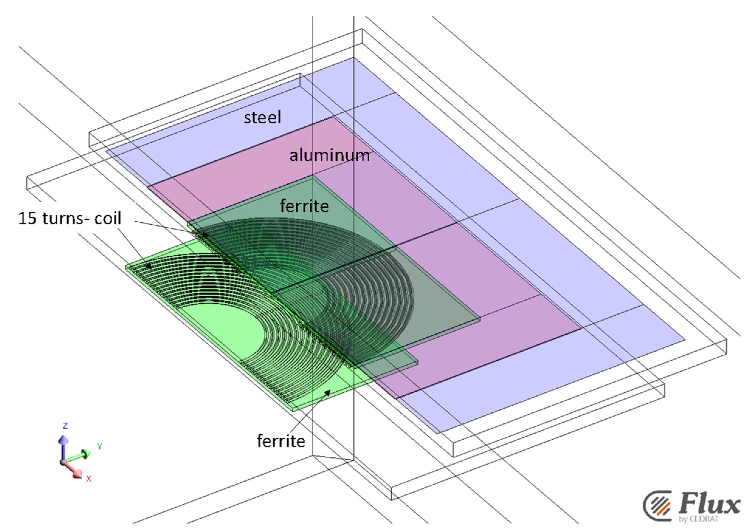
2.1. Lumped Parameter Computation

The self- and mutual-inductances at different alignment conditions were computed using the 3D finite element model (FEM) described in [22]. In order to reduce the number of mesh elements, only half of the device was implemented in Flux 3D software (released by Altair Engineering, Inc., Troy, MI, USA, ref. [44]) by exploiting the system symmetry. The two-faced coils with an airgap of 140 mm exhibit 15 turns made of Litz’s wire (internal diameter 150 mm, turn diameter 4.5 mm, turn pitch 8 mm) and are equipped with a magnetic field concentrator, a ferrite layer with a side of 404 mm made of 3C95 (Ferroxcube, initial relative permeability of 3000, a saturation flux density of 530 mT, [45]). The car frame has been modeled as a steel sheet made of ASTM A1008 steel (resistivity 14.2 × 10⁻⁸ Ωm and initial relative permeability of 1000), 1000 mm × 800 mm, and a thickness equal to 0.7 mm. An aluminum sheet (600 mm × 600 mm) with a thickness of 0.76 mm has been positioned between the ferrite layer and the car frame to reduce the effect of the eddy currents on the steel. In order to reduce the number of mesh elements, the eddy current in the aluminum and steel sheet were computed using a “shell formulation” [46,47,48]. This way the mesh of the model has an average of 1,680,000 second-order tetrahedral elements. The device geometry is shown in Figure 1. All material properties have been considered constant, as reported in Table 1.
The lumped parameters were computed by solving a time harmonic magnetic problem using the T   ϕ formulation with T   electric vector potential and ϕ magnetic scalar potential [49]. The following equations, subject to suitable boundary conditions, were solved in the model domain [22,50,51]:
× σ 1   × T   +   j ω μ   ( T   ϕ ) = 0
Then, the vector of the magnetic field, H   , is given by:
H   = ( T   ϕ )
To evaluate the lumped parameters of the system, the 3D model of the device has been coupled with an electric circuit that includes a perfect current source and a resistive load, whose resistance may be varied, from the actual value of the load connected to the receiving coil to a very high value to simulate an open circuit (Figure 2) [47,48].
The FE model in Figure 1 is ‘fed’ by the circuit in Figure 2. Mutual and self-inductances have been calculated for different relative positions of the receiving and transmitting coil (step of 50 mm). The self-inductances, Li, have been computed by supplying one coil at a time with a current, Is, of 1 Arms at 85 kHz frequency and by measuring the voltage, Vs, at the ends of the supplied coil itself. The not-powered coil is connected to a load resistance, RL = 106 Ω, to represent an open-circuit condition:
This way, the self-inductance is:
L i = V S ω I s      
The mutual inductance, M, has been evaluated by (4), measuring the voltage, VL, induced on the not supplied coil.
M = V L ω I s
Table 2 shows the self and mutual inductances evaluated with FEAs and uses Equations (3) and (4) for different distances of the receiving coil axis with respect to the transmitting coil axis [22].

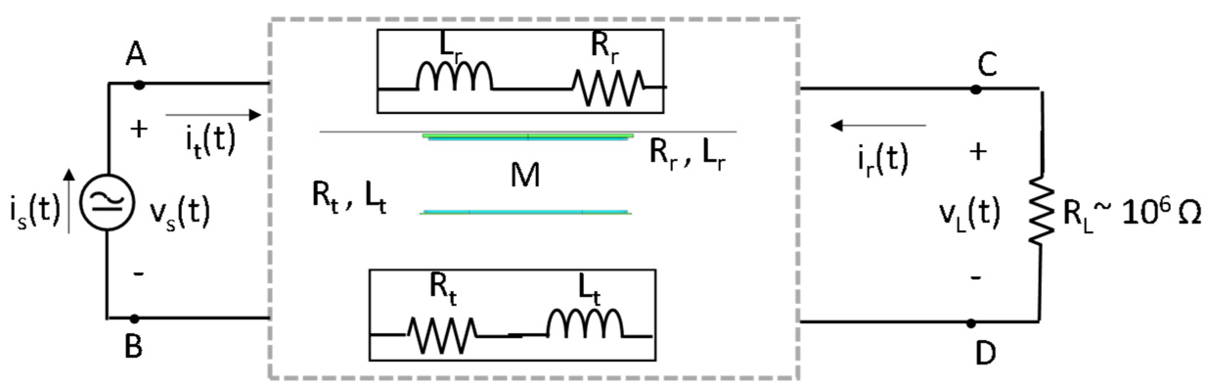
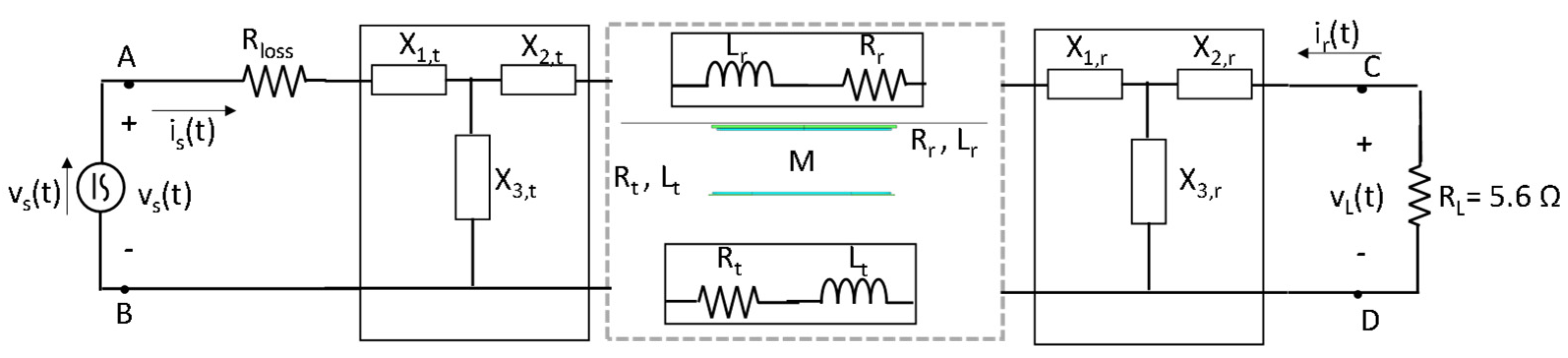
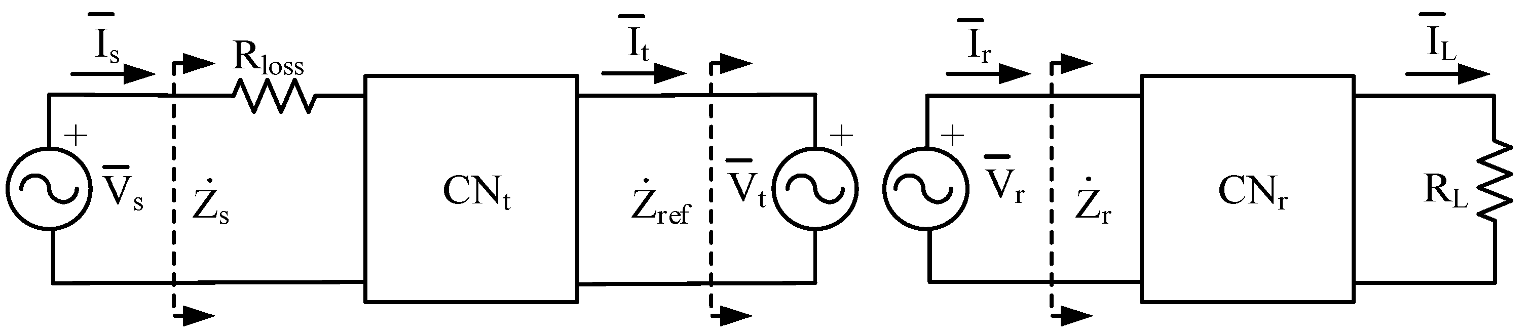
2.2. Compensation Network

A compensation network is a reactive circuit interposed between the power supply, constituted by a high frequency inverter controlled with the phase-shift technique [52], and the transmission coil or between the receiving coil and the load. In the scheme of Figure 3, a general TT network, with three reactances per side, is represented. The optimization of the compensation network in static condition, i.e., for the aligned case, has been performed in previous works [53,54]. In the dynamic WPTS, the optimal CNs must be searched considering the lumped parameters; L and M are not constant in time.
The power, PL, transferred to the load and the, η, of the system are the functions to maximize.
CNs operate on the basis of the resonance phenomenon to achieve a minimum of the reactance seen at the inverter output in correspondence with the nominal supply frequency, ω0. This condition helps to minimize the voltage needed to supply the transmitting side CN-coil assembly and forces the inverter output current to be nearly sinusoidal despite the quasi-square waveform of the output voltage. From this condition, it is derived that the analysis of WPTSs can be performed by hypothesizing that all the involved electrical quantities are sinusoidal at 85 kHz. According to this hypothesis, the circuit of Figure 3 can be redrawn in the scheme of Figure 4, where phasor quantities are considered. Subscripts t and r indicate the receiving and transmitting coils, respectively.
The power dissipated in Rloss represents the conduction losses of the supply inverter, which are proportional to the current flowing in the power switches and, during the dead times, in the free-wheeling diodes. The commutation losses depend on the parasitic capacitance of the switches and diodes and on the voltage applied across them [55,56]. The dc side voltage of the inverter is not an optimized design variable and hence the switching losses are not affected by the optimization process. For this reason, and considering that in the experimental setup taken as reference they are a small fraction of the conduction losses, they are not considered in the representation of Figure 4.
The transferred power and efficiency have been obtained by a sequence of steps that starts by computing the equivalent impedance, Zr, seen by the voltage source, V ¯ r , that represents the voltage induced on the receiving coil. By definition, this is:
Z ˙ r V ¯ r I ¯ r
The transferred power, Z ˙ p u , depends on the values of the reactances forming CNr and on RL, whose values must be known in order to evaluate power and efficiency. To this aim, we can introduce the reflected impedance, Z ˙ r e f , that is a function of Z ˙ p u , M, and the supply angular frequency, ω, but that does not depend on the topology of the CNs:
Z ˙ r e f V ¯ t I ¯ t = ω 2 M 2 Z ˙ r
obtained considering the relations (5) and (7)
V ¯ r = j ω M I ¯ t ,   V ¯ t = j ω M I ¯ r ,
which relate the voltages and currents of the transmitting and receiving coils.
The impedance, Z ˙ s , seen by the voltage supply is computed using Rloss, Z ˙ r e f , and the optimized reactances of CNt.
In computing PL and η, the magnitude of V s is conveniently set to 1 V, so that the reciprocal of Z ˙ s corresponds to the supply current, I s , in the hypothesis of a perfectly linear system. From the supply voltage and current and knowing the values of CNr reactances, it is possible to determine the current, I t , flowing in the transmitting coil. From the latter, the induced voltage, V r , is computed according to the first of (7). The current, I r , is the ratio between V r and the previously computed Z ˙ r . Finally, from V r and I r and knowing the CNr reactances, it is possible to evaluate the current, I L , and the power transferred to the load:
P L = 1 2 R L | I L | 2
where | I L | is the rms magnitude of I L .
The active power delivered by the voltage supply is obtained as:
P s = 1 2 e [ V s I s * ]
where the operator, e [ · ] , computes the real part of its argument.
Finally, the power transfer efficiency is computed using:
η = P L / P s

2.3. Inverse Problem

The reactances of the CNs in Figure 3, coupled to the WPTS device, have been designed considering the movement of the receiving inductor at a constant speed. The power transferred to the load, PL, has been evaluated considering nine different positions of the receiving coil with respect to the transmitting one. Different positions correspond to different self and mutual inductances, as reported in Table 2. In each position, the power transfer efficiency and the power transferred to the load have been evaluated following the procedure described in the previous section.
In order to find the CNs that are the best trade-off in the design of a dynamic WPTS, an inverse problem (identification problem) has been solved considering different combinations of power and efficiency. To this aim, three different formulations of the optimization problem have been considered.
The first problem is based on the following objective functions (OF) to be maximized:
P L s = i = 1 9 P L i ( x i )
η 1 = P L , 1 ( x 1 ) P t , 1 ( x 1 )
where PLi(xi) is the power transferred to the load in the i-th position and PL,1(x1) and Pt,1(x1) are the power transferred to the load and the power at the transmitting coil, respectively, in the aligned position.
In this optimization problem, the total amount of transferred power and the efficiency in the aligned case are considered because their maximum values occur in that position.
The second problem considers the first four displacements (from 0 to 150 mm, see Table 2) and it is based on the following OFs:
P η = min ( P L i ( x i ) · η i ( x i ) )   i = 1 , , 4
P h = m a x ( P L i ( x i ) ) m i n ( P L i ( x i ) )   i = 1 , , 4
The OF (13) is to be maximized, while function (14) is to be minimized. In particular, maximizing the Ph function means searching for a power transfer homogeneity over the first four positions.
Finally, the third problem considers the function Ph, i.e., Equation (14) and the following (15), to be maximized:
P η 4 = i = 1 4 P L i ( x i ) · η i ( x i )
The OFs (13)–(15) use only the first four displacements out of the nine used to compute the inductive parameters L and M because, as can be deduced by analysis of the second row of Table 2, the considered coils are affected by the null-power point phenomenon [22,41], i.e., a value of displacement exists where the mutual inductance is 0 even if the coils are still partially faced. For these coils, the null-power point happens with a displacement between 200 mm and 300 mm. At the null power point, PL is zero irrespectively from the topology and the reactances of the CN. With displacements higher than 200 mm, M is small and consequently there is no reason to attempt to maximize PL in conditions where it is inherently zero or small.
The three problems were solved considering the following constraint: Z ω 0 / Z ω 100 < 1 and Z ω 0 / Z ω 0.01 < 1 , where Zω0 is the impedance at the supply inverter output at the nominal supply angular frequency ω0 (@ 85 kHz), and Zω100 and Zω0.01 are the impedances at the angular frequencies ω100 (100ω0) and ω0.0010/100). The first constraint is opposed to the flow of distorted currents in the CN-coils assembly, while the second constraint avoids the flowing of low frequency current in the CN-coil assembly. Together, the two constraints enforce the minimum of the inverter load impedance at ω0 discussed in the previous subsection.
The second and third problems have been solved by including, eventually, the following constraint: the CN at the receiving side must be composed of capacitors only and the CN at the transmitting side can be composed of inductors or capacitors. In the following, when the constraint is applied, the relevant problem is marked with the receiving capacitor “R.C.” label.
This latter constraint has a twofold rationale: one aspect is related to the reduction of the cost of the CNs because inductors are much more expensive than setting up capacitors by series and parallel connection of standard elements; the second aspect is related to the parasitic resistances of inductors that usually cause more losses than those of capacitors, thus negatively affecting the overall efficiency of the WPTS.
The optimization problems are solved by using a Non-dominated-Sorting-Genetic Algorithm, NSGA-II algorithm [30,31,57]. In all the considered problems, the initial population has 25 individuals, and the stopping criterion is 200 iterations. Three runs of the optimization algorithm with different initial individuals have been performed for each problem.

3. Results and Discussion

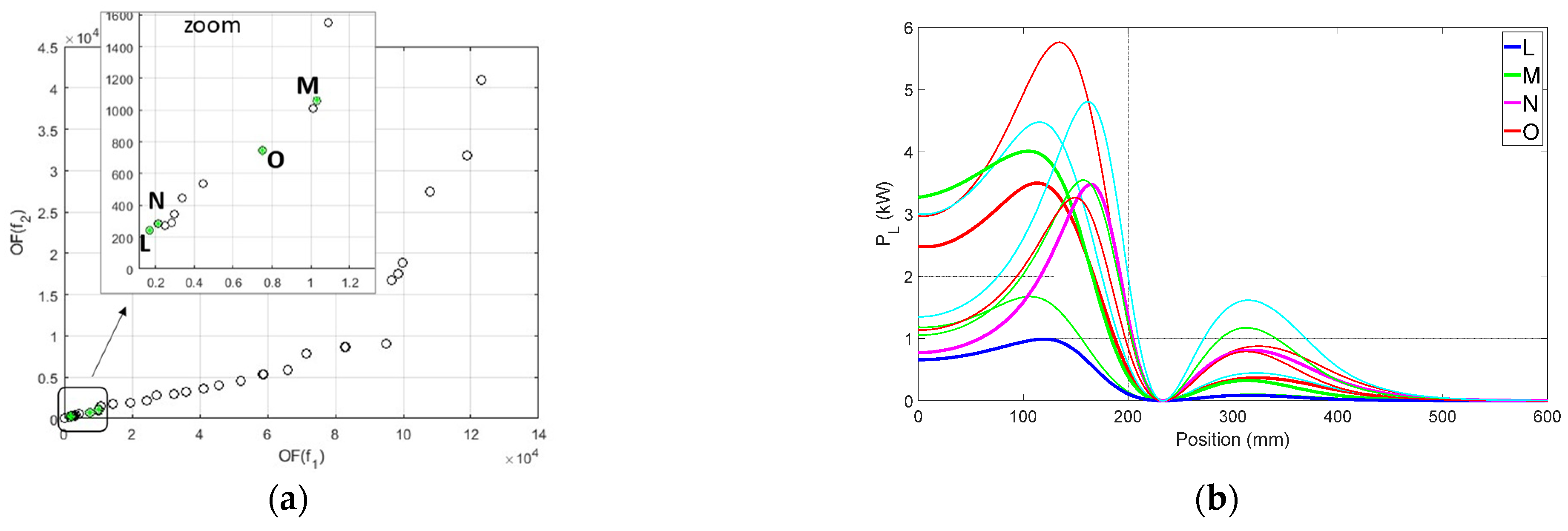
3.1. Selection of Promising Individuals

The selection of the best individuals has been performed considering the specific application of the prototypal WPTS. The prototype and, in particular, its coils, have been designed to charge the battery of a minicar with a maximum power of 600 W. As a matter of fact, for safety reason, the coils and the power converters of the WPTS have been oversized and have been tested for up to 1 kW of output power. It is likely that a WPTS with the same architecture could be easily modified to sustain a power of 3.3 kW, which is the nominal power of the domestic grid in Italy. The control algorithm of the prototype regulates the output power to the required value but, in order to minimize the control effort, it is reasonable to implement CNs that inherently limit the oscillations of the output power due to M variation. Finally, the power transfer efficiency when the coils are aligned must be reasonably high.
From these considerations, among the individuals obtained at the end of the optimization process, only those that satisfy the following conditions have been considered for the subsequent selection:
  • Output power in aligned condition between 0.5 kW and 3.3 kW;
  • Ratio of maximum output power to the power in aligned condition lower than 4.5;
  • Power transfer efficiency in aligned condition higher than 0.8.
It is worth noting that the previous conditions could not be met by any solution found by solving the third optimization problems without the constraint of having a CNr made only of capacitors.
The values of the self- and mutual-inductances reported in Table 2 have been interpolated with a spline to evaluate their value with a position resolution of 1 mm. These latter ones, together with the reactances of the individuals that satisfy the above-mentioned conditions, have been used to compute the profiles of the transferred power as a function of the coils’ relative position and some other related quantities used to evaluate the most promising CNs. In more detail, these quantities are:
  • The profile of the transferred power, PL(x), as a function of the receiving coil position, x;
  • The transferred power in the aligned position, PL(0);
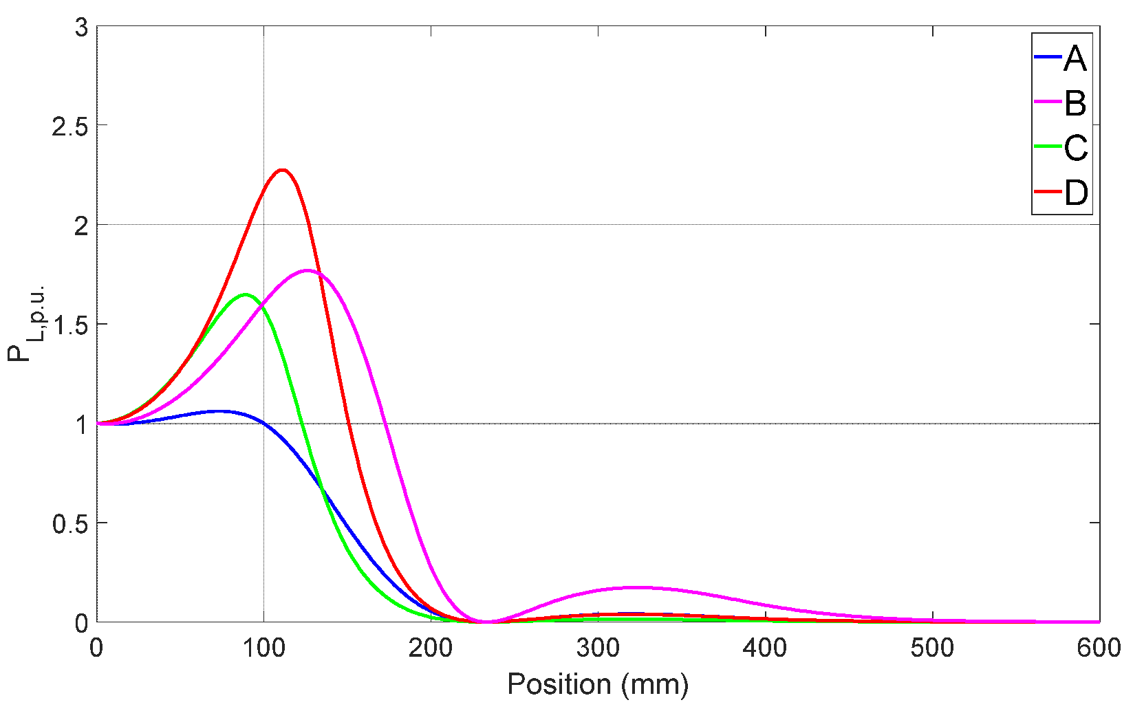
  • The profile of the per unit (p.u.) transferred power, PL,p.u(x), defined as the ratio of PL(x) to PL(0);
  • The maximum p.u. transferred power, PL,p.u.,max;
  • The maximum position, xpmax, where PL,p.u(x) ≥ 1;
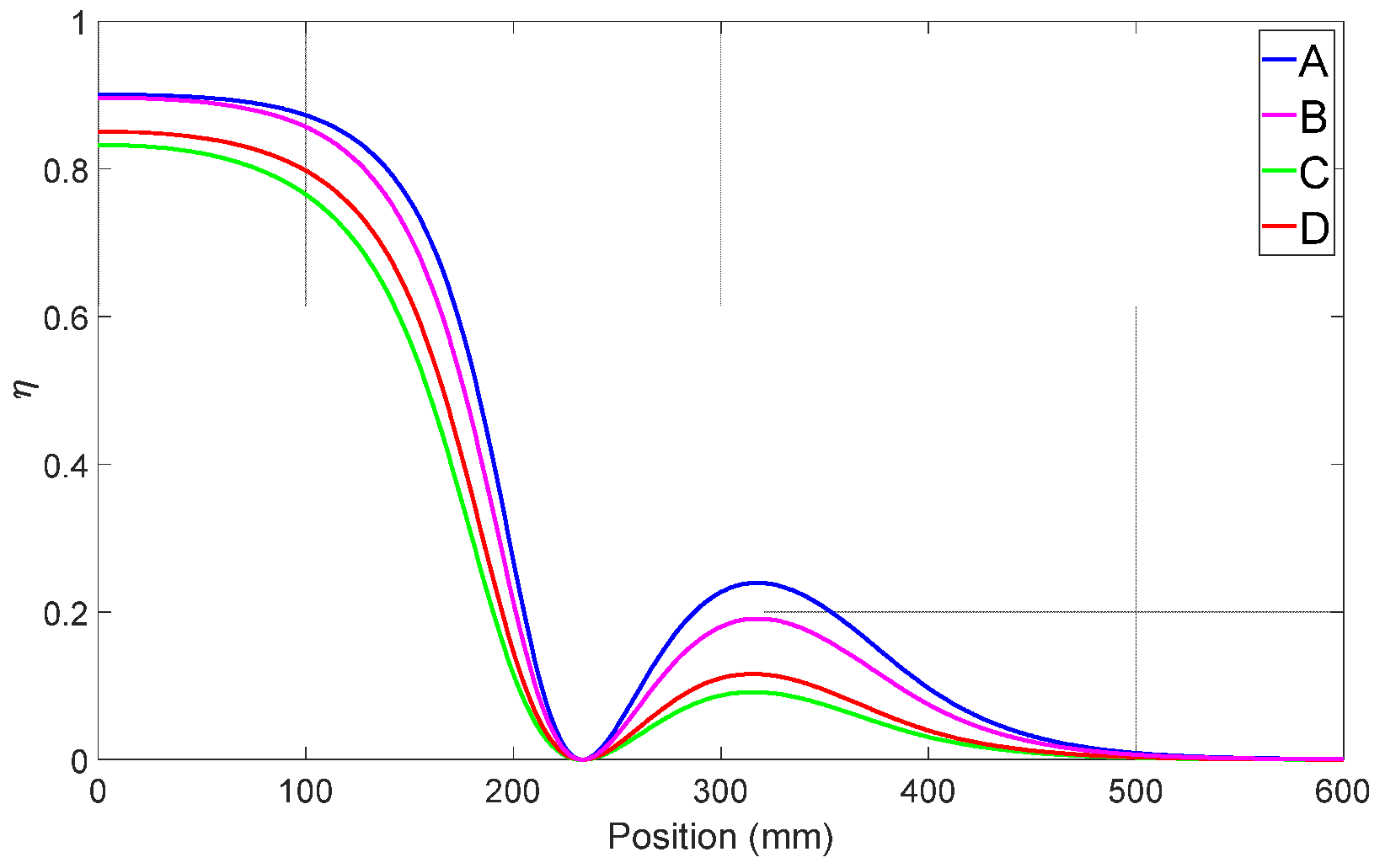
  • The power transfer efficiency in the aligned position;
  • The maximum of the power per unit PL,p.u., PL,p.u.,max.

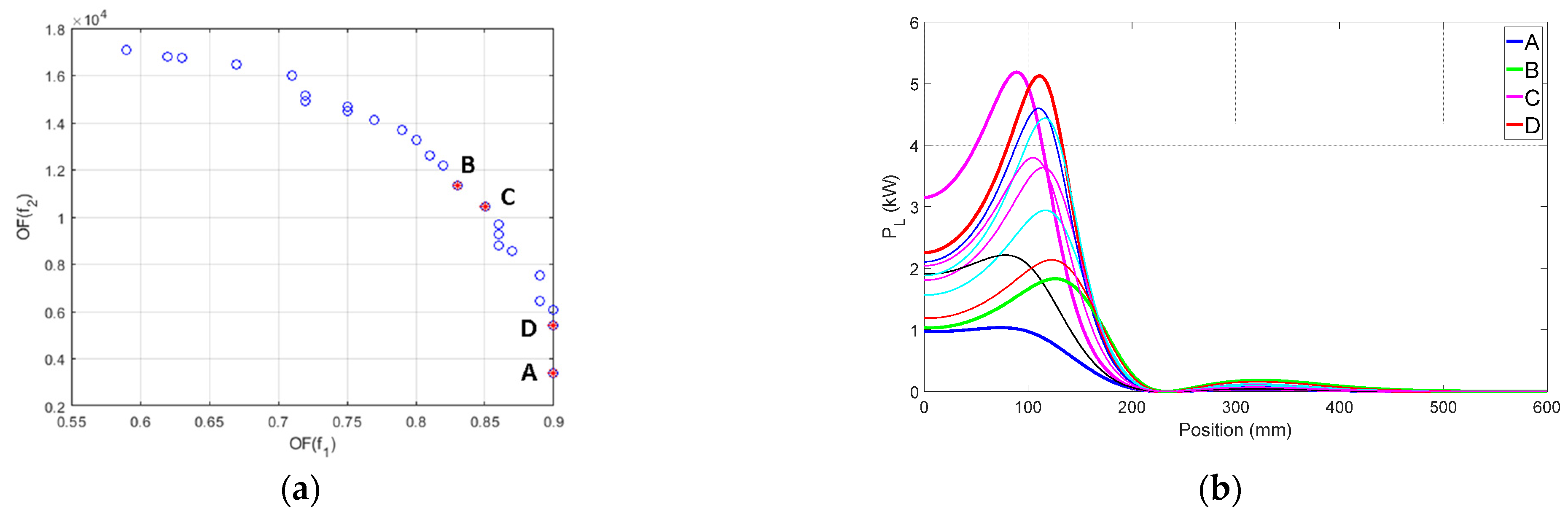
3.2. Results of Problem 1

The Pareto front related to the solutions of Problem 1 is represented in Figure 5a. Considering the whole amount of 75 optimized individuals (three runs with 25 individuals each), only 11 individuals satisfy the three conditions stated in Section 3.1, and their power vs. position profiles are reported in Figure 5b, highlighting with thicker lines the profiles relevant to particular individuals described in the following analysis. All the profiles, apart from the one denoted with the “A”, exhibits the typical behavior of the series–series compensation where, when the mutual inductance, M, decreases, there is an initial increase in the transferred power and then a steep descent. This behavior requires the adjustment of the supply voltage of the transmitting coil, while the distance increases in order to avoid excessive solicitation of the coils and of the power converters. The characteristics of solutions A, B, C, and D of Figure 5 are summarized in Table 3, together with those of other individuals obtained from the optimization algorithm applied to the other two problems. Table 4 lists the reactances forming the CNs of the individuals characterized in Table 3.
Considering the original requirement of transferring a power of 600 W, the individuals that originate the power profiles denoted with “A” and “B” are the most promising. The first one allows to transfer a power of approximately 0.97 kW that is quite constant without the need of adjusting the supply voltage from the aligned position to the maximum position, xpmax, of 100 mm. The second individual enlarges the range where it is possible to transfer the power, PL(0), up to xpmax = 173 mm and limits the maximum transferred power to 1.76 times PL(0). This latter characteristic is highlighted in Figure 6, where PL,p.u. is plotted as a function of the position itself. The figure reports only the profiles relevant to the individuals A, B, C, and D in order to make its analysis easier.
When the transferred power must be maximized, individuals that give the profiles denoted with C or D should be selected. Individual C transfers a PL(0) = 3.15 kW and maintains this power capability up to xpmax = 123 mm with PL,p.u.,max, equal to 1.64. The individual D maintains the power capability of the aligned position up to xpmax = 151 mm, but at the expense of a lower PL(0), equal to 2.25 kW, and a higher PL,p.u.,max, which reaches 2.27.
The power transfer efficiency corresponding to individuals A, B, C, and D is plotted in Figure 7, and its value in the aligned position is reported in Table 3. As a general result, it can be noted that an increase in the transferred power causes a decrease in the efficiency and that the effect is stronger when the coils are misaligned.

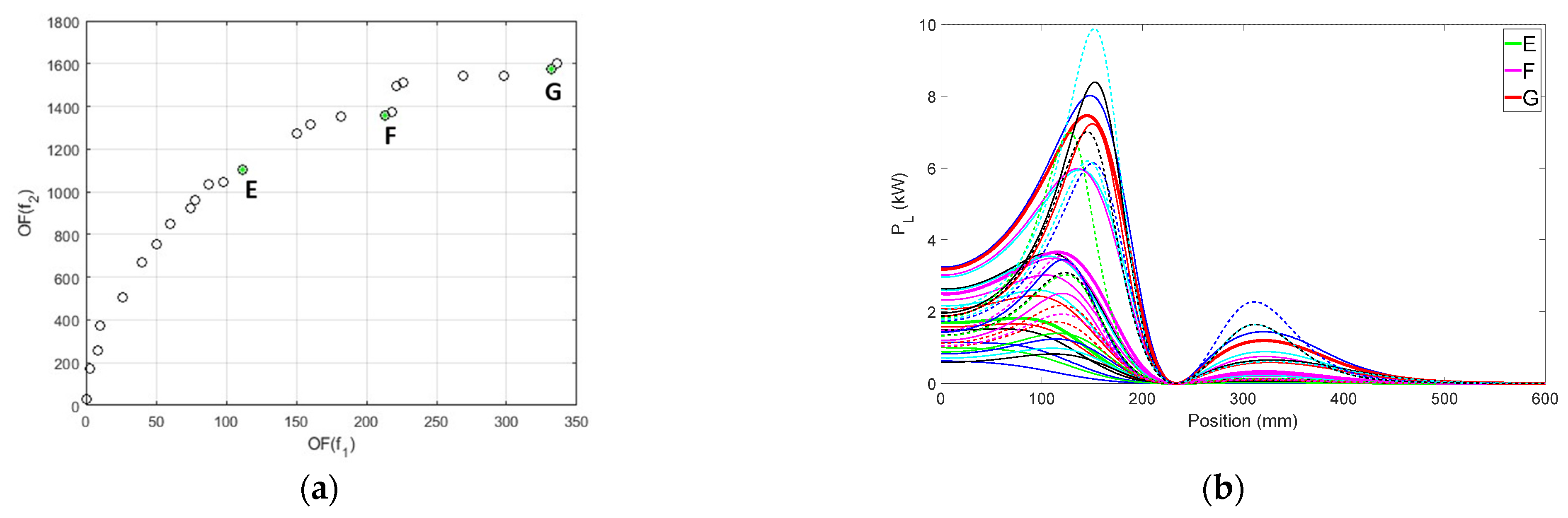
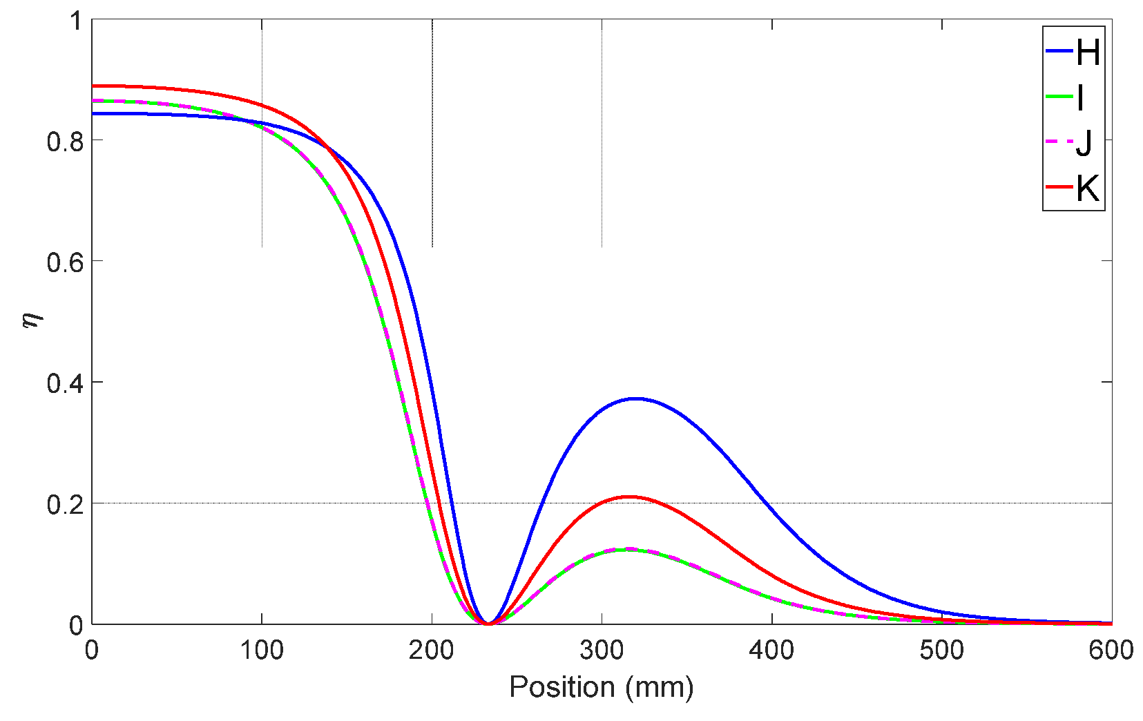
3.3. Results of Problem 2 and CNr Made of Capacitors or Inductors

The Pareto front of Problem 2 is represented in Figure 8a. In this case, the OFs (13), to be maximized, and (14), to be minimized, are used and, among the whole 75 optimized individuals, 36 individuals satisfy the three conditions stated in Section 3.1. Their power vs. position and per unit power vs position profiles are reported in Figure 8b and Figure 9. Two individuals whose per unit power profiles are similar to those of A and B are selected and are denoted as E and F. As a matter of fact, the power, PL(0), transferred using individuals E and F is roughly twice the power relevant to A and B, respectively. The individual E gives nearly the same PL,p.u.,max and xpmax as the individual A, while F originates a lower PL,p.u.,max than B but with a shorter xpmax.
Considering the individuals with the highest power transferred, the one marked with “G” gives the most balanced performance because its relevant PL(0) and xpmax are very near to the highest among the 36 selected individuals and PL,p.u.,max is sensibly lower than the maximum. Considering the power profiles, individual G outperforms D, but unfortunately it originates an efficiency about 3% lower, as can be seen in Figure 10, which plots the efficiency profiles of G, E, and F, and in Table 3. All the analyzed individuals in terms of power profile are marked with green dots in Figure 8a.
This result regarding the efficiency is general, and indeed all the profiles of the 36 selected individuals lie below the profiles of the 11 elements selected in Section 3.2. Figure 7, Figure 8, Figure 9 and Figure 10 confirm that the individuals E, F, and G are characterized by lower efficiency than A, B, C, and D. Moreover, in this case there is not an inverse relation between PL(0) and η because G, which gives the maximum PL(0), has an efficiency higher than F and G. The latter ones have nearly equal efficiency profiles.

3.4. Results of Problem 2 and CNr Made Only of Capacitors

The Pareto front of Problem 2 is shown in Figure 11a. As in the previous subsection, in this case, 36 of the optimized individuals satisfy the three conditions given in Section 3.1. Figure 11b shows that there is a group of individuals characterized by transferring to a load more or less the same PL(0), lower than 1 kW. Among them, the most suitable for the application described in the Introduction is denoted with the letter “H”; its transferred power in the aligned position is just enough to satisfy the specification of the prototypal WPTS; its xpmax is rather long whilst its PL,p.u.,max is acceptable. It could be compared with individual A considered in Section 3.2, but its efficiency in the aligned position is approximately 6% lower.
Considering the power transfer capability, the individual denoted with “I” can be considered as one of the best because of its high PL(0) and low PL,p.u.,max, as shown in Figure 12. Individual I is comparable with individual F, whose characteristics have been described in the previous subsection, but offers a higher efficiency. The individual marked with “J” has a high xpmax that reaches 175 mm. It is comparable with the individual B described in Section 3.2, but suffers from a lower efficiency.
From the point of view of efficiency in the aligned position, individual K is the best: it is slightly overperformed only by individual A, but transfers more than twice its power. This result regarding efficiency can be explained considering that in the power transfer efficiency computation the losses of the CNs capacitors are neglected as they are considered much lower than the losses in the inductors. Consequently, the individuals H, I, J, and K, which do not have inductors on the receiving side, give higher efficiency than the individuals E, F, and G considered in Section 3.3. As shown in Figure 13, the efficiency profiles of I and J are practically equal. Individuals K and H give, respectively, the highest and the lowest efficiency in the aligned position and K exhibit a higher xpmax than H; however, when the coil misalignment exceeds 138 mm, the efficiency of H becomes the highest among the considered individuals, being 10% higher than that of K. All the analyzed individuals in terms of power profile are marked with green dots in Figure 11a. The power profile characteristics and the reactances relevant to individuals H, I, J, and K are listed in Table 3 and Table 4.

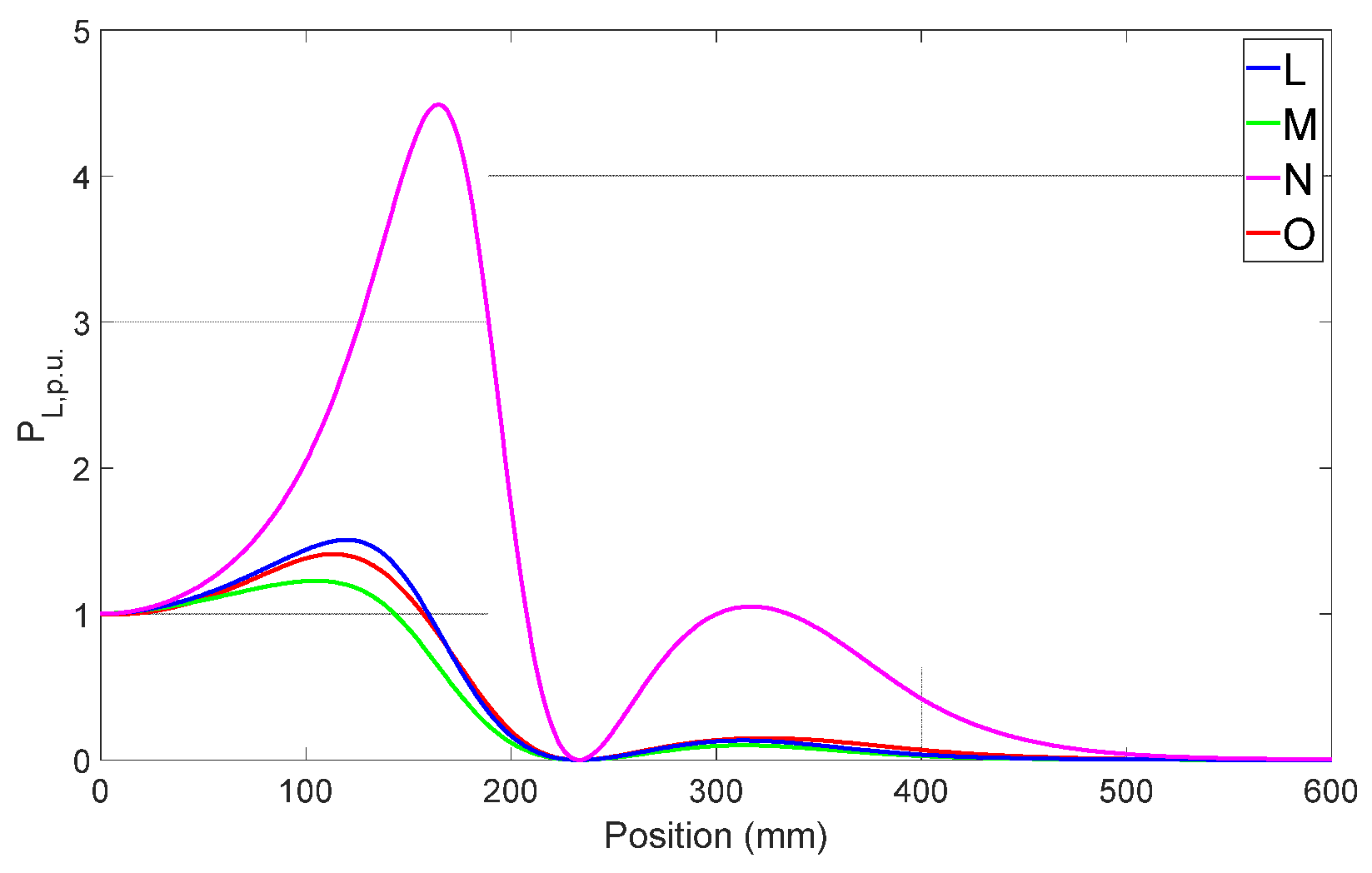
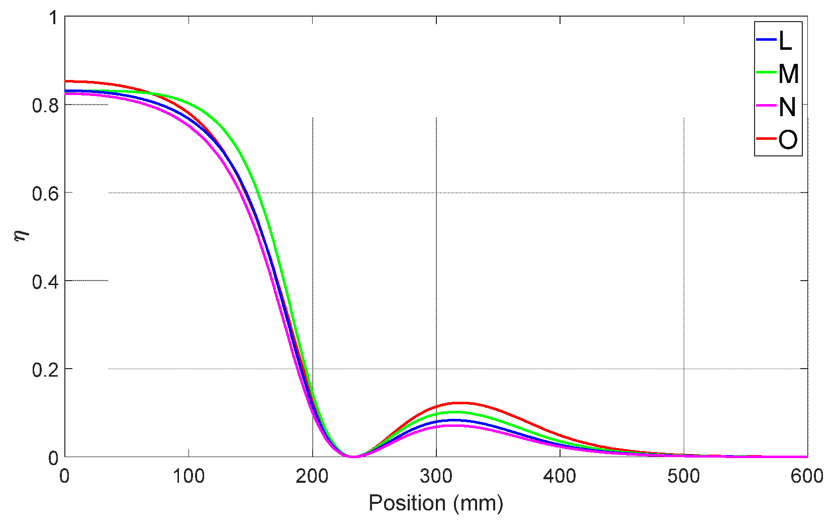
3.5. Results of Problem 3 and CNr Made Only of Capacitors

The Pareto front of Problem 3 is shown in Figure 14a. Among the 75 individuals of this group, only 10 satisfy the conditions of Section 3.1. As shown in Figure 14b, they can be roughly divided into two groups, one supplying PL(0) around 1 kW and the other with PL(0) around 3 kW.
Among the latter ones, individual M gives the highest PL(0) with the lowest PL,p.u.,max. Unfortunately, Figure 15 and Table 3 show that its xpmax is the shortest and so it is not suitable for a dynamic WPTS.
The efficiency profile of individual M is reported in Figure 16 and has more or less the same behavior of the efficiency profile relevant to individual H plotted in Figure 13; in the aligned condition, the efficiency is lower than that of the other individuals, but it becomes the highest when the distance to the aligned position increases. For Problem 3, the maximum efficiency in the aligned condition is achieved by individual O, even if it is outperformed by other individuals obtained using the first or the second pair of OFs. All the analyzed individuals in terms of power profile are marked with green stars in Figure 14a.
Considering the individuals with PL(0) around 1 kW, the one marked with the “L” supplies the lowest power equal to 660 W, comparable with the performance of individual H considered in the Section 3.4; with respect to the later one, L has a longer pmax and approximately the same efficiency, but its PL,p.u.,max is considerably higher and hence it requires a stronger control effort to regulate the output power.
The pmax of the individual denoted with “N” is the longest among the total of the individuals resulting from the optimization process and results of 207 mm. This performance is obtained at the expense of a very high PL,p.u.,max, which reaches 4.48, and of a profile of efficiency that lies under the others for any position.

4. Conclusions

The paper deals with the optimization of the CNs of a dynamic WPTS. Three pairs of OFs have been used, with one or two additional constraints regarding the CN’s topology. After the optimization, a number of possible design solutions have been obtained. They have different characteristics that allow one to select the solutions or group of solutions that are most suitable for the given specifications. For example, individuals that have the capacity to transfer significant power while the coils are shifted at a relative long distance have been recognized; other individuals showed success in limiting the transmitted power increment while the coils move, while others are characterized by high efficiency.
The perfect solution that maximizes at the same time all these aspects cannot be found; nevertheless, the approach detailed in the paper can be considered as a valuable tool for the WPTS designer. Indeed, after filling Table 2 with the inductive parameters acquired from the FEM simulation of the considered pair of coils, and adjusting consequently the maximum index, I, in OFs (13)–(15), this approach can be applied to the design of a CN for any pair of coils, whether equal to each other, as in the considered case, or with different architectures [19].

Author Contributions

Conceptualization, M.B. and P.D.B.; methodology, M.F. and P.D.B.; validation, M.B. and E.S.; formal analysis, M.B., M.F., and E.S.; investigation, E.S.; resources, M.B. and M.F.; data curation, M.B., M.E.M., and E.S.; writing—original draft preparation, M.E.M., M.B, and E.S.; writing—review and editing, P.D.B. and M.E.M.; visualization, E.S. and M.B.; supervision, M.E.M. and P.D.B.; funding acquisition, M.B. and M.F. All authors have read and agreed to the published version of the manuscript.

Funding

This research received no external funding.

Institutional Review Board Statement

Not applicable.

Data Availability Statement

Not applicable.

Conflicts of Interest

The authors declare no conflict of interest.

References

  1. Barmada, S.; Tucci, M.; Fontana, N.; Dghais, W.; Raugi, M. Design and Realization of a Multiple Access Wireless Power Transfer System for Optimal Power Line Communication Data Transfer. Energies 2019, 12, 988. [Google Scholar] [CrossRef] [Green Version]
  2. Gaire, P.; Vital, D.; Khan, M.R.; Chibane, C.; Bhardwaj, S. Adhoc mobile power connectivity using a wireless power transmission grid. Sci. Rep. 2021, 11, 17867. [Google Scholar] [CrossRef] [PubMed]
  3. Kindl, V.; Frivaldsky, M.; Zavrel, M.; Pavelek, M. Generalized Design Approach on Industrial Wireless Chargers. Energies 2020, 13, 2697. [Google Scholar] [CrossRef]
  4. Shen, S.; Clerckx, B. Joint Waveform and Beamforming Optimization for MIMO Wireless Power Transfer. IEEE Trans. Commun. 2021, 69, 5441–5455. [Google Scholar] [CrossRef]
  5. Naik, M.K.; Bertoluzzo, M.; Buja, G. Design of a contactless battery charging system. In Proceedings of the 2013 Africon, Pointe aux Piments, Mauritius, 9–12 September 2013; pp. 1–6. [Google Scholar] [CrossRef]
  6. Patel, B.R. Wireless Charging of Implantable Pacemaker’s Battery. J. Biosens. Bioelectron. 2018, 9, 258. [Google Scholar] [CrossRef]
  7. Sun, L.; Ma, D.; Tang, H. A review of recent trends in wireless power transfer technology and its applications in electric vehicle wireless charging. Renew. Sustain. Energy Rev. 2018, 91, 490–503. [Google Scholar] [CrossRef]
  8. Feng, H.; Tavakoli, R.; Onar, O.C.; Pantic, Z. Advances in High-Power Wireless Charging Systems: Overview and Design Considerations. IEEE Trans. Transp. Electrif. 2020, 6, 886–919. [Google Scholar] [CrossRef]
  9. Choi, S.Y.; Gu, B.W.; Jeong, S.Y.; Rim, C.T. Advances in Wireless Power Transfer Systems for Roadway-Powered Electric Vehicles. IEEE J. Emerg. Sel. Top. Power Electron. 2015, 3, 18–36. [Google Scholar] [CrossRef]
  10. Brizi, D.; Fontana, N.; Tucci, M.; Barmada, S.; Monorchio, A. A Spiral Resonators Passive Array for Inductive Wireless Power Transfer Applications With Low Exposure to Near Electric Field. IEEE Trans. Electromagn. Compat. 2020, 62, 1312–1322. [Google Scholar] [CrossRef]
  11. Mou, X.; Gladwin, D.T.; Zhao, R.; Sun, H. Survey on magnetic resonant coupling wireless power transfer technology for electric vehicle charging. IET Power Electron. 2019, 12, 3005–3020. [Google Scholar] [CrossRef] [Green Version]
  12. Cirimele, V.; Diana, M.; Freschi, F.; Mitolo, M. Inductive Power Transfer for Automotive Applications: State-of-the-Art and Future Trends. IEEE Trans. Ind. Appl. 2018, 54, 4069–4079. [Google Scholar] [CrossRef]
  13. Orasanu, A.; Dragomir, A.; Bobaru, L.; Iordache, M.; Deleanu, S. On Optimization of Wireless Power Transfer Systems. In Proceedings of the 2018 International Symposium on Fundamentals of Electrical Engineering (ISFEE), Bucharest, Romania, 1–3 November 2018; pp. 1–6. [Google Scholar] [CrossRef]
  14. Bi, Z.; Kan, T.; Mi, C.C.; Zhang, Y.; Zhao, Z.; Keoleian, G.A. A review of wireless power transfer for electric vehicles: Prospects to enhance sustainable mobility. Appl. Energy 2016, 179, 413–425. [Google Scholar] [CrossRef] [Green Version]
  15. Lukic, S.; Pantic, Z. Cutting the Cord: Static and Dynamic Inductive Wireless Charging of Electric Vehicles. IEEE Electrif. Mag. 2013, 1, 57–64. [Google Scholar] [CrossRef]
  16. Siqi, L.; Mi, C.C. Wireless Power Transfer for Electric Vehicle Applications. IEEE J. Emerg. Sel. Top. Power Electron. 2015, 3, 4–17. [Google Scholar] [CrossRef]
  17. Triviño, A.; González-González, J.M.; Aguado, J.A. Wireless Power Transfer Technologies Applied to Electric Vehicles: A Review. Energies 2021, 14, 1547. [Google Scholar] [CrossRef]
  18. Di Capua, G.; Maffucci, A.; Stoyka, K.; Di Mambro, G.; Ventre, S.; Cirimele, V.; Freschi, F.; Villone, F.; Femia, N. Analysis of Dynamic Wireless Power Transfer Systems Based on Behavioral Modeling of Mutual Inductance. Sustainability 2021, 13, 2556. [Google Scholar] [CrossRef]
  19. Bertoluzzo, M.; Buja, G.; Dashora, H.K. Design of DWC System Track with Unequal DD Coil Set. IEEE Trans. Transp. Electrif. 2017, 3, 380–391. [Google Scholar] [CrossRef]
  20. Bavastro, D.; Canova, A.; Cirimele, V.; Freschi, F.; Giaccone, L.; Guglielmi, P.; Repetto, M. Design of Wireless Power Transmission for a Charge While Driving System. IEEE Trans. Magn. 2014, 50, 965–968. [Google Scholar] [CrossRef]
  21. Yakala, R.K.; Pramanick, S.; Nayak, D.P.; Kumar, M. Optimization of Circular Coil Design for Wireless Power Transfer System in Electric Vehicle Battery Charging Applications. Trans. Indian Natl. Acad. Eng. 2021, 6, 765–774. [Google Scholar] [CrossRef]
  22. Bertoluzzo, M.; Di Barba, P.; Forzan, M.; Mognaschi, M.E.; Sieni, E. Wireless Power Transfer System in Dynamic Conditions: A Field-Circuit Analysis. Vehicles 2022, 4, 234–242. [Google Scholar] [CrossRef]
  23. Bertoluzzo, M.; Di Barba, P.; Dughiero, F.; Mognaschi, M.E.; Sieni, E. Multicriterion Synthesis of an Electric Circuit for Wireless Power Transfer Systems. Przegląd Elektrotechniczny 2020, 96, 188–192. [Google Scholar] [CrossRef]
  24. Zhang, W.; Mi, C.C. Compensation Topologies of High-Power Wireless Power Transfer Systems. IEEE Trans. Veh. Technol. 2016, 65, 4768–4778. [Google Scholar] [CrossRef]
  25. Feng, H.; Cai, T.; Duan, S.; Zhang, X.; Hu, H.; Niu, J. A Dual-Side-Detuned Series–Series Compensated Resonant Converter for Wide Charging Region in a Wireless Power Transfer System. IEEE Trans. Ind. Electron. 2018, 65, 2177–2188. [Google Scholar] [CrossRef]
  26. Nguyen, V.-T.; Vu, V.-B.; Gohil, G.; Fahimi, B. Coil-to-Coil Efficiency Optimization of Double-Sided LCC Topology for Electric Vehicle Inductive Chargers. IEEE Trans. Ind. Electron. 2022, 69, 11242–11252. [Google Scholar] [CrossRef]
  27. Sun, S.; Liu, Z.; Hou, Y.; Li, X.; Xie, Y.; Zhai, H.; Wei, X. Analysis of harmonic characteristics based on improved double-LCC compensation network structure. Energy Rep. 2022, 8, 891–902. [Google Scholar] [CrossRef]
  28. Barmada, S.; Dionigi, M.; Mezzanotte, P.; Tucci, M. Design and experimental characterization of a combined WPT–PLC system. Wirel. Power Transf. 2017, 4, 160–170. [Google Scholar] [CrossRef] [Green Version]
  29. Barmada, S.; Tucci, M. Optimization of a magnetically coupled resonators system for Power Line Communication integration. In Proceedings of the 2015 IEEE Wireless Power Transfer Conference (WPTC), Boulder, CO, USA, 13–15 May 2015; pp. 1–4. [Google Scholar] [CrossRef]
  30. Deb, K.; Pratap, A.; Agarwal, S.; Meyarivan, T. A fast and elitist multiobjective genetic algorithm: NSGA-II. IEEE Trans. Evol. Comput. 2002, 6, 182–197. [Google Scholar] [CrossRef] [Green Version]
  31. Deb, K. Multi-Objective Optimization Using Evolutionary Algorithms, 1st ed.; John Wiley & Sons: Chichester, UK; New York, NY, USA, 2001. [Google Scholar]
  32. Forrest, S. Genetic Algorithms: Principles of Natural Selection Applied to Computation. Science 1993, 261, 872–878. [Google Scholar] [CrossRef] [Green Version]
  33. Schmitt, L.M. Theory of genetic algorithms. Theor. Comput. Sci. 2001, 259, 1–61. [Google Scholar] [CrossRef] [Green Version]
  34. Srinivas, N.; Deb, K. Multiobjective optimization using nondominated sorting in genetic algorithms. Evol. Comput. 1994, 2, 221–248. [Google Scholar] [CrossRef]
  35. Fonseca, C.M.; Fleming, P.J. An overview of evolutionary algorithms in multiobjective optimization. Evol. Comput. 1995, 3, 1–16. [Google Scholar] [CrossRef]
  36. Lahanas, M.; Schreibmann, E.; Milickovic, N.; Baltas, D. Evolutionary Multi-Criterion Optimization; Springer: Berlin/Heidelberg, Germany, 2003; p. 70. [Google Scholar] [CrossRef]
  37. Li, S.; Wang, L.; Guo, Y.; Tao, C.; Ji, L. Power Stabilization With Double Transmitting Coils and T-Type Compensation Network for Dynamic Wireless Charging of EV. IEEE J. Emerg. Sel. Top. Power Electron. 2020, 8, 1801–1812. [Google Scholar] [CrossRef]
  38. Yang, M.; Li, Y.; Du, H.; Li, C.; He, Z. Hierarchical Multiobjective H-Infinity Robust Control Design for Wireless Power Transfer System Using Genetic Algorithm. IEEE Trans. Control Syst. Technol. 2019, 27, 1753–1761. [Google Scholar] [CrossRef]
  39. Ning, P.; Onar, O.; Miller, J. Genetic algorithm based coil system optimization for wireless power charging of electric vehicles. In Proceedings of the 2013 IEEE Transportation Electrification Conference and Expo (ITEC), Detroit, MI, USA, 16–19 June 2013; pp. 1–5. [Google Scholar] [CrossRef]
  40. Buja, G.; Bertoluzzo, M.; Mude, K.N. Design and Experimentation of WPT Charger for Electric City Car. IEEE Trans. Ind. Electron. 2015, 62, 7436–7447. [Google Scholar] [CrossRef]
  41. Budhia, M.; Covic, G.A.; Boys, J.T. Design and Optimization of Circular Magnetic Structures for Lumped Inductive Power Transfer Systems. IEEE Trans. Power Electron. 2011, 26, 3096–3108. [Google Scholar] [CrossRef]
  42. Budhia, M.; Boys, J.T.; Covic, G.A.; Huang, C. Development of a Single-Sided Flux Magnetic Coupler for Electric Vehicle IPT Charging Systems. IEEE Trans. Ind. Electron. 2013, 60, 318–328. [Google Scholar] [CrossRef]
  43. J2954_202010 Wireless Power Transfer for Light-Duty Plug-in/Electric Vehicles and Alignment Methodology. 2020. Available online: https://www.sae.org/standards/content/j2954_202010/ (accessed on 4 July 2022).
  44. FLUX, (Altair). Available online: https://altairhyperworks.com/product/flux (accessed on 4 July 2022).
  45. Ferroxcube, (n.d.). Available online: https://www.ferroxcube.com/en-global (accessed on 4 July 2022).
  46. Le-Duc, T.; Meunier, G.; Chadebec, O.; Guichon, J.-M. A New Integral Formulation for Eddy Current Computation in Thin Conductive Shells. IEEE Trans. Magn. 2012, 48, 427–430. [Google Scholar] [CrossRef] [Green Version]
  47. Le-Duc, T.; Meunier, G.; Chadebec, O.; Guichon, J.-M.; Bastos, J.P.A. General Integral Formulation for the 3D Thin Shell Modeling. IEEE Trans. Magn. 2013, 49, 1989–1992. [Google Scholar] [CrossRef] [Green Version]
  48. Guerin, C.; Meunier, G. 3-D Magnetic Scalar Potential Finite Element Formulation for Conducting Shells Coupled With an External Circuit. IEEE Trans. Magn. 2012, 48, 323–326. [Google Scholar] [CrossRef]
  49. Morisue, T. Magnetic vector potential and electric scalar potential in three-dimensional eddy current problem. IEEE Trans. Magn. 1982, 18, 531–535. [Google Scholar] [CrossRef]
  50. Meunier, G. (Ed.) The Finite Element Method for Electromagnetic Modeling; ISTE ; Wiley: London, UK; Hoboken, NJ, USA, 2008. [Google Scholar]
  51. Binns, K.J.; Lawrenson, P.J.; Trowbridge, C.W. The Analytical and Numerical Solution of Electric and Magnetic Fields; Wiley: Chichester, UK, 1992. [Google Scholar]
  52. Esteve, V.; Jordán, J.; Dede, E.J.; Sanchis-Kilders, E.; Martinez, P.J.; Maset, E.; Gilabert, D. Optimal LLC Inverter Design With SiC MOSFETs and Phase Shift Control for Induction Heating Applications. IEEE Trans. Ind. Electron. 2022, 69, 11100–11111. [Google Scholar] [CrossRef]
  53. Bertoluzzo, M.; Giacomuzzi, S.; Sieni, E. Automatic Optimization of the Compensation Networks of a Wireless Power Transfer System. Energies 2020, 13, 5298. [Google Scholar] [CrossRef]
  54. Bertoluzzo, M.; Di Barba, P.; Forzan, M.; Mognaschi, M.E.; Sieni, E. Multiobjective optimization of compensation networks for wireless power transfer systems. COMPEL-Int. J. Comput. Math. Electr. Electron. Eng. 2021, 41, 674–689. [Google Scholar] [CrossRef]
  55. Patil, D.; Sirico, M.; Gu, L.; Fahimi, B. Maximum efficiency tracking in wireless power transfer for battery charger: Phase shift and frequency control. In Proceedings of the 2016 IEEE Energy Conversion Congress and Exposition (ECCE), Milwaukee, WI, USA, 18–22 September 2016; pp. 1–8. [Google Scholar] [CrossRef]
  56. Graovac, D.D.; Pürschel, M.; Kiep, A. MOSFET Power Losses Calculation Using the Data- Sheet Parameters. Infineon Appl. Note 2006, 1, 1–23. [Google Scholar]
  57. Zitzler, E.; Thiele, L. Multiobjective evolutionary algorithms: A comparative case study and the strength Pareto approach. IEEE Trans. Evol. Comput. 1999, 3, 257–271. [Google Scholar] [CrossRef] [Green Version]
Figure 1. Geometry of the implemented half FE model of the WPTS system.
Algorithms 15 00261 g001
Figure 2. FE model coupled with the supply and load circuit for lumped parameter evaluation.
Algorithms 15 00261 g002
Figure 3. Scheme of the compensation networks to be optimized in the constant-speed moving condition.
Algorithms 15 00261 g003
Figure 4. Phasor representation of the WPTS.
Algorithms 15 00261 g004
Figure 5. (a) Pareto front of the improved solutions and (b) Power vs. position for Problem 1. In panel (a) the red stars show the selected individuals in the analysis.
Algorithms 15 00261 g005
Figure 6. Per unit power vs. position (Problem 1).
Algorithms 15 00261 g006
Figure 7. Efficiency vs. position (Problem 1).
Algorithms 15 00261 g007
Figure 8. (a) Pareto front of Problem 2 (CNs made of capacitors and inductors) and (b) Power vs. position. In panel (a) the green stars show the selected individuals for the analysis.
Algorithms 15 00261 g008
Figure 9. Per unit power vs. position (Problem 2 and both CNs made of capacitors and inductors).
Algorithms 15 00261 g009
Figure 10. Efficiency vs. position for (Problem 2 and both CNs made of capacitors and inductors).
Algorithms 15 00261 g010
Figure 11. (a) Pareto front of Problem 2 and (b) Power vs. position fore results of Problem 2 and receiving side CN made only of capacitors. In panel (a), the green stars show the selected individuals in the analysis.
Algorithms 15 00261 g011
Figure 12. Per unit power vs. position (Problem 2 and receiving side CN made only of capacitors).
Algorithms 15 00261 g012
Figure 13. Efficiency vs. position (Problem 2 and receiving side CNs made only of capacitors).
Algorithms 15 00261 g013
Figure 14. (a) Pareto front of the improved solutions for Problem 3 and receiving side CN made only of capacitors and (b) Power vs. position. In panel (a) the green dots show the selected individuals in the analysis.
Algorithms 15 00261 g014
Figure 15. Per unit power vs. position (Problem 3 and receiving side CN made only of capacitors).
Algorithms 15 00261 g015
Figure 16. Efficiency vs. position (Problem 3 and receiving side CNs made only of capacitors).
Algorithms 15 00261 g016
Table 1. Electrical characteristics of the materials used in the FE model.
Materialμrρ [Ωm]
Ferrite 3C953000 (saturation 530 mT)5
steel100014 × 10−8
aluminum12.6 × 10−8
Table 2. Self and mutual inductances of the WPTS device for different positions.
x [mm]050100150200300400500600
M [μH]28.926.018.810.253.1−2.7−1.6−0.5−0.1
Lt [μH]116.4116.7117.2117.7117.5115.7117.3118.7117.4
Lr [μH]113.2113.2113.2113.0112.7111.1110.1110.0110.1
Table 3. Power profile characteristics. R.C.: only capacitors on the CNs at receiving coil.
Power ProfilePL(0) (kW)PL,p.u..maxxpmax (mm)ηOpt. ProblemCNs Composition
A0.971.061000.901
B1.031.761730.891
C3.151.641230.831
D2.252.271510.851
E1.691.071050.822
F2.501.461590.802
G3.182.341910.822
H0.631.271410.842R.C.
I2.801.491610.862R.C.
J2.521.821750.862R.C.
K2.072.141720.892R.C.
L0.661.511600.833R.C.
M3.261.231430.833R.C.
N0.774.482070.823R.C.
O2.481.411570.853R.C.
Table 4. Reactances of optimized individuals. Value of the OFs considered in the solved problem.
Power ProfileX1,t (Ω)X2,t (Ω)X3,t (Ω)X4,t (Ω)X5,t (Ω)X6,t (Ω)O.F(f1)O.F(f2)
A63.3−5.81−34.2−12.9−37.7252.10.903388.33
B68.4−0.7−34.0−10.3−38.7251.90.8311,363.72
C65.6−1.6−33.8−17.6−44.0251.70.8510,442.11
D66.4−0.2−33.9−18.6−41.4252.10.905394.30
E126.1−296.0−306.3−13.2−40.3460.9112.011103.99
F125.9−295.7−287.1−20.0−34.7463.6213.001355.46
G127.8−290.9−294.8−10.3−45.1464.3331.611573.74
H−46.2−19.9165.9−15.2−57.6−158.3401.62254.47
I20.8−98.8−37.0−35.2−33.3−219.41516.51915.10
J20.3−96.7−39.4−35.4−33.5−219.41866.401192.95
K−68.629.0214.5−58.3−2.4−498.41794.831365.26
L−149.2−223-280.6−1.0−76.0−317.91705.49243.15
M7.0−71.4−10.4−0.8−84.4−301.310,305.271064.63
N−153.9−234.280.9−1.1−76.2−318.12153.36284.35
O−35.16.863.20−60.7−497.27496.86746.16
Publisher’s Note: MDPI stays neutral with regard to jurisdictional claims in published maps and institutional affiliations.

