Abstract
Mechanical vibrations have a significant impact on ride comfort; the driver is constantly distracted as a result. Volumetric engine inertial unbalances and road profile irregularities create mechanical vibrations. The purpose of this study is to employ optimization algorithms to identify structural elements that contribute to vibration propagation and to provide optimal solutions for reducing structural vibrations induced by engine unbalance and/or road abnormalities in a motorcycle. The powertrain assembly, swing-arm assembly, and vibration-isolating mounts make up the vibration-isolating system. Engine mounts are used to restrict transferred forces to the motorbike frame owing to engine shaking or road irregularities. Two 12-degree-of-freedom (DOF) powertrain motorcycle engine systems (PMS) were modeled and examined for design optimization in this study. The first model was used to compute engine mount parameters by reducing the transmitted load through the mounts while only considering shaking loads, whereas the second model considered both shaking and road bump loads. In both configurations, the frame is infinitely stiff. The mount stiffness, location, and orientation are considered to be the design parameters. The purpose of this study is to employ computational methods to minimize the loads induced by shaking forces. To continue the optimization process, Grey Wolf Optimizer (GWO), a meta-heuristic swarm intelligence optimization algorithm inspired by grey wolves in nature, was utilized. To demonstrate GWO’s superior performance in PMS, other optimization methods such as a Genetic Algorithm (GA) and Sequential Quadratic Programming (SQP) were used for comparison. To minimize the engine’s transmitted force, GWO was employed to determine the optimal mounting design parameters. The cost and constraint functions were formulated and optimized, and promising results were obtained and documented. The vibration modes due to shaking and road loads were decoupled for a smooth ride.
1. Introduction and Background
Ride comfort is one of the most important dynamic aspects of motorcycles. Ride comfort is mostly harmed by mechanical and acoustic vibrations, which expose the driver to continual disturbances. Mechanical vibrations are mostly caused by volumetric engine inertial unbalances and variable road profiles [1].
In recent years, the need for vehicle/motorcycle vibration and noise performance has increased. It is vital to have a mounting mechanism that works better in terms of vibration isolation. The link between performance and design elements in mounting systems, on the other hand, is complex, and determining the conditions necessary to achieve optimal isolation performance is difficult. Engine mounts that support the engine while limiting the engine’s transmitted force to the frame have recently been improved using optimization approaches. Under defined boundary constraints, optimization algorithms can explore the design search domain to discover the optimal design variables that will reduce mechanical vibration-transmitted stresses to the frame [2]. The motorcycle engine mount mechanism, as well as the motorcycle frame shape design, has been optimized using various optimization approaches.
The design optimization of motorcycle engine mounts has long been a crucial issue in the motorcycle business. In this work, a few effective and durable optimization techniques are used to optimize the motorcycle engine mounting system. Engine mounts are rubber parts that go between the engine and the body or frame of a motorcycle to isolate and eliminate mechanical vibrations. They also secure the engine to the body/frame and improve ride comfort by isolating or limiting engine vibration transfer to the body/frame. Force and motion isolation are two of the most important considerations for engineers when designing an engine mounting system. Motorcycle engines have reciprocating elements that create shaking forces due to the movement of various sections of the engine. The main goal is to limit such tremors to a bare minimum. This is accomplished by sustaining the powertrain using a strong support or isolator.
Johnson and Subhedar [3] designed and published a computer simulation and optimization method for determining the best mounting system configuration that matches user-defined system dynamic characteristics. Their goal was to figure out the optimal first mounting configuration. They discussed the challenges and limitations of generic engine mounting system designs. They improved the design of the powertrain mounting system, focusing on natural frequency and the energy-decoupling rate as optimization targets, and attained good results. For vibration insulator design, Arai et al. [4] established a simple optimization approach. The stiffness, location, and tilt of each insulator were used as design factors in their model. A new optimization approach has been developed based on a performance index and the sensitivity of design elements. A designer might easily examine the performance of a mount system in development and determine the optimum system specs, according to the authors. Heyns [5] used an optimization method to create stiff body mounting arrangements in 1996. He employed sequential quadratic programming (SQP) as a direct optimization method. As design elements that may be modified to limit force transfer to the vehicle body, mounting positions and stiffness coefficients were considered. Foumani et al. [6] devised an experimental/numerical approach for engine mount optimization. They provided an optimization approach for active and passive vibration isolators or absorbers in any mechanical system. Rather than using a mathematical model of the vehicle or its components, their proposed technique optimizes based on experimental data. Two optimization based approaches were utilized to tackle an issue by Kaul et al. [7]. Due to dynamic stresses, the first strategy minimizes the load delivered to the frame while keeping engine displacement within a set envelope. The second procedure adjusts the mount settings to modify the system’s natural frequencies to avoid specified predetermined operational frequency ranges. In both approaches, the authors used the local optimization search method. For determining the optimal engine-mounting configuration, Courtelle et al. [8] developed a MATLAB/FRONTIER design technique. The authors created a GA (MOGA) based on a multi-objective optimization technique and determined that it meets industry standards for preliminary engine suspension system design. They claim that their method meets both comfort and packing requirements in a reasonable length of time while also considering the solution’s robustness. Kual et al. [9] investigated the impact of frame flexibility on an improved engine mounting method for improved motorcycle vibration isolation. They developed a theoretical model to depict the structural dynamics of the engine mount system on a motorcycle. Due to enforced stresses, the optimization approach used optimizes the load given to the frame while keeping engine displacement within set limitations. The stiffnesses, locations, and orientations of the mounts are used as design elements in their model. Kual and Anoop [10] regarded the engine mounts as triaxial spring-damper systems, and the front-end assembly was represented as a lumped mass. They created a complete vehicle model to solve the engine mount optimization challenge, which entails decreasing the overall force imparted to the frame while remaining compliant with packaging and other constraints. The mount system’s stiffness, position, and orientation vectors were used as design variables in their model’s optimization problem. Forces and moments induced by engine imbalance, as well as loads conveyed through the tire patch due to high amplitude, low frequency bump loads, were among the imposed loads. Nariman-Zadeh et al. [11] used multi-objective optimization using genetic algorithms (MOGA) on a five-degree-of-freedom vehicle vibration model, and the optimization results clearly improved vibration isolation performance. Cheli F., et al. [12] developed a technique for statistically forecasting inertial engine unbalances induced by the crank mechanism and, ultimately, the countershaft, lowering the consequent propagating vibrations transmitted to the frame by optimizing the engine mount structure. Design issues included the quantity of the engine mounts, their optimal positions, and their viscous elasticity qualities. Their goal was to discover the optimal engine mount architecture that would limit the engine block’s shaking effects on the frame in terms of forces. Ooi and Ripin optimized an engine mounting system dynamically [13], considering frequency-dependent stiffness and loss factor. The optimal placements and orientation angles of the individual engine mounts were found to lower the system’s mean force transmissibility across a wide frequency range, and the dynamic characteristics in all three principal directions were measured in their model. The application of optimization methods in the design of fluid mounts was examined by Ahn Y. et al. [14]. The authors explored the role of the notch and resonance peak in the dynamic stiffness of fluid mounts. The utility of two additional optimization approaches for selecting the parameter combination that generated the deepest notch and shortest resonant peak, the Enhanced Genetic Algorithm (EGA) and Sequential Quadratic Programming (SQP), was also investigated. The literature on the application of meta-heuristic algorithms (MHs) or evolutionary algorithms (EAs) for engine mounting and part design was reviewed by Ayarani-N et al. [15] using finite element (FE) and multibody dynamics (MBD) simulation techniques. The balance of a single cylinder motorcycle engine’s crankshaft was changed by Ganguly et al. [16] to reduce vibration at the motorcycle’s touch sensitive point (TSP), which includes the handlebar and footrest. In 2016, AlKhatib and Dhingra [17] presented a vibration isolation model for a motorcycle mounting system. Their methodology only considers shaking loads, with the purpose of disconnecting vibrations (decoupling) by lowering transmitted loads. Scappaticci et al. [2] improved the performance of a tubular frame intended for Moto2 racing by using an optimization technique based on the size of the frame’s single pipes and involving the creation of an objective function to reduce the frame’s weight by managing its stiffness. Kerathana and Nizamuddin [18] used CATIA for modeling and Hyper-works for finite element analysis to examine the topology optimization of a ‘Chevrolet beat’ engine-mounting bracket. By evaluating the design and material arrangement, they were able to lower the weight of the engine-mounting bracket. Xu et al. [19] developed a vehicle vibration model based on GA and fusion robustness analysis, with the targets being the decoupling rate and modal frequency of the mountings in all directions, and GA optimizing the stiffness of the three mountings. Using a multi-objective evolutionary algorithm, Sleesongsom and Bureerat [20] proposed a new design technique for the vibration mitigation of a single-cylinder engine (MOEA). Design components such as the engine’s shape and sizing characteristics are shown in [21] to decrease inertia and pressure forces.
The purpose of this study is to employ computational design optimization algorithms to determine optimal design parameters that minimize the loads induced by shaking forces, which eventually isolate mechanical vibrations. The following is a breakdown of the structure of the paper. Section 2 provides background information on engine mount system optimization techniques, specifically global optimization algorithms. In Section 3, we presetn advanced computerized automated optimization approaches that can be used to improve the problem’s design. GWO [22], GA [23], and SQP [24] were used to find the best design parameters for the two 12 DOF PMS models given. In Section 4, the computational simulation is carried out, and the simulation results are presented and explained in detail. Finally, the final section is summarized in the conclusion.
2. Engine Mounting System Optimization Procedures
A typical engine mount system consists of three to four engine mounts. The overall performance of the mounting system, as well as the performance of individual mounts, determines how the mounting system behaves. In the design of an engine mount system, stiffness coefficients, position, and orientation of individual mounts are routinely used design criteria. Mounts were traditionally built utilizing time-consuming analysis techniques, experimental methodologies, or technical skills. If the development activity’s initial mounting configuration is close to optimum, this situation is greatly enhanced. Defining a near-optimal first mounting arrangement is difficult due to the convoluted nature of engine inertia qualities and packing constraints on mount locations imposed by manufacturability factors. An efficient computational design approach, black-box optimization techniques, and accurate modeling methodologies are crucial for such applications.
A flurry of optimization strategies has been introduced over the years. New concepts and strategies have been developed to deal with highly nonlinear engineering design difficulties, which are intrinsically complicated. Calculating the gradient for such engineering problems is extremely time-consuming and expensive, requiring significant computational effort and resources. Non-gradient optimization techniques (stochastic or heuristic optimization algorithms) became appealing and promising because of their enhanced efficiency and capacity to extract information from the search space without experiencing any computational problems.
Despite the availability of a variety of optimization algorithms to solve complex engineering problems for a variety of applications, the complexity of engineering design challenges mandates the use of a reliable and efficient optimization technique. Such challenges have just recently begun to be addressed by swarm intelligence optimization approaches. Most swarm intelligence-based algorithms use multi-agent algorithms, which are inspired by social organisms such as bees, fireflies, and ants, as well as other animal societies including herds of birds, schools of fish, and packs of wolves. The firefly algorithm (FFA) [25] uses firefly-flashing activity instead of fish and bird behaviour in the traditional particle swarm optimization (PSO) [26]. Cuckoo search (CS) [27] is based on the brood parasitism of some cuckoo species, whereas the bat algorithm depends on the echolocation of foraging bats. Ant colony optimization (ACO) [28] is based on the chemical language of social ants, whereas bee algorithms (BA) [29,30] are based on honeybee foraging behaviour. Swarm intelligence-based algorithms have become quite popular and have been widely used in recent years due to their capacity to disseminate information among several agents. The efficiency of such algorithms is improved by self-organization, co-evolution, and learning over iterations. Another argument is that large-scale optimization may be easily handled by parallelizing several agents. As a result, nonlinear and difficult design optimization problems involving costly analysis and simulation methods such as finite element analysis (FEA) and computational fluid dynamics are well suited to such optimization strategies (CFD). Yildiz et al. [31] examined the efficacy of ten modern meta-heuristic strategies for optimizing the design of six mechanical engineering optimization problems. Their comparative analysis optimization methods were recently developed and shown to be promising and capable of generating good results. Yildiz et al. [31] employed some of these methodologies in a comparative study. The methods include particle swarm optimization (PSO) [25], moth–flame optimization (MFO) [32], ant lion optimizer (ALO) [33], water cycle algorithm (WCA) [34], the evaporation rate water cycle algorithm WCA (ER-WCA) [35], grey wolf optimizer (GWO) [22], mine blast algorithm (MBA) [36], whale optimization algorithm (WOA) [37], and salp swarm algorithm [38].
The engine mount application in this study is optimized using two types of swarm intelligence optimization algorithms, with the purpose of minimizing transmitted forces from the engine to the frame and hence mechanical vibrations. A local search optimization method is also used to compare performance and show how swarm intelligent optimization algorithms perform better in real-world engineering applications. These three methods are most notable in that they are utilized to determine the optimal design variables that minimize the objective function while taking into consideration the application limits, eventually lowering the transmitted forces caused by engine vibrations.
3. Utilized Design Optimization Algorithms
There are various advantages of potential design optimization methods over other procedures. For starters, they drastically cut computational time, which is a sophisticated feature for costly, non-linear, high-dimensional, and computationally heavy models. Second, such algorithms are known for their robustness, accuracy, and high convergence efficiency (convergence speed).
This article’s optimization approach employs a range of optimization methods from several categories. Swarm optimization intelligence, evolutionary, and gradient-based optimization techniques were used to optimize two motorcycle engine mount models. These optimization strategies have already been tested on real-world problems and have proven to be effective and dependable [23,25,26]. Yildiz [31] presents a comprehensive and in-depth examination, as well as the application of ten newly developed algorithms, including GWO, to six mechanical design problems. The next sections give an overview of the overall context and promising optimization tactics employed in this study to complete the optimization process for PMS.
3.1. Grey Wolf Optimizer (GWO)
In 2014, Mirjalili et al. [22] proposed the grey wolf optimizer (GWO), a groundbreaking swarm intelligence optimization algorithm that simulates various animals’ hunting and searching activities. GWO is a nature-inspired metheuristic that is based on the behavior of a pack of wolves. It explores the search space in hope of finding an optimal solution. It is an iterative method that is used to solve optimization problems. It primarily mimics the natural wolf leadership structure and hunting mechanism. Four types of grey wolves are employed to replicate the leadership structure: alpha, beta, delta, and omega. GWO also executes the three core hunting processes: locating prey, enclosing prey, and attacking prey. Muro et al. [39] summarized the hunting strategy of GWO in first approaching and chasing the prey, followed by an encircling maneuver around the prey until it completely stops moving, and finally attacking of the prey when it is exhausted.
In terms of optimization performance, the authors in [22] show that ordinary GWO is better than other optimization algorithms in the same family such as PSO, GSA, DE, and FEP algorithms.
The pseudo code of GWO (Algorithm 1) can be summarized as follows:
| Algorithm 1. Grey Wolf Optimizer |
| Initialize the grey wolf population Xi, i = 1…n |
| Initialize a, A, and C |
| Calculate the fitness of each search agent |
| Xalpha = the best search agent |
| Xbeta = the second best search agent |
| Xgamma= the third best search agent |
| Whilet < max number of iterations do |
| for each search agent do |
| Randomly initialize r1 and r2 |
| 1.1 Update the position of the current search agent |
| 2.1 Update a, A, and C |
| Calculate the fitness of all search agents |
| Update Xalpha, Xbeta, Xgamma |
| t = t + 1 |
| Return Xalpha |
3.2. Genetic Algorithm (GA)
The genetic algorithm (GA) [23] is an evolutionary optimization (EO) algorithm. GA is modeled after natural selection, in which the fittest individuals are picked for reproduction to produce children for the following generation. The goal of these tactics is to use randomization, mating behavior, and mutations to evolve our solution. A genetic profile is assigned to each particle, which is utilized to determine its fitness. The particles with the highest fitness will reproduce more, whereas those with the lowest fitness will die and be replaced. Crossover reproduction procedures are utilized, mixing both parents’ genes, although mutations are possible, allowing the new generation to evolve further. Five phases are considered in GA, intial population; fitness function; selection; crossover; and mutation. GA is used in this study to find the optimal design variables for reducing transmitted forces from the engine to the frame. Mechanical vibrations are decreased or isolated as a result.
3.3. Gradient-Based Algorithms
Gradient-based algorithms are one type of deterministic optimization technique. When the gradient is easily defined, it can deal with problems involving unimodal and convex functions. The gradient of the goal function and the initial guess or starting search point are crucial in these algorithms. They resemble a ball shot aloft that is retracted downhill by gravity until it lands in a stable spot. SQP methods solve a sequence of optimization sub-problems, each of which optimizes a quadratic model of the objective subject to a linearization of the constraints. The downside of these algorithms when dealing with multi-model objective functions is that they are easily locked in local optimum rather than global optimum. SQP (Sequential Quadratic Programming) [24] is an example of such algorithms that will be used to compare and explain whether gradient-based methods succeed or fail in tackling MPS design optimization in this study. The failure of gradient-based algorithms to converge to global solutions or handle complex optimization problems is widely known. It is used in this research to show that such algorithms fail horribly in complex engineering issues such as PMS. Some researchers, including AlKhatib in [40], employed a gradient-based technique and were pleased with the results; however, some parameters, such as the initial search point, needed to be changed or adjusted in order for the algorithm to converge to an optimal solution. The pseudo code of SQP (Algorithm 2) can be summarized as follows:
| Algorithm 2. Sequential Quadratic Programming |
| 3.1 begin |
| Choose a starting point Xo and approximation Ho to the Hessian |
| repeati = 1, 2,… |
| Solve a QP sub-problem QPi to obtain the search direction Si |
| Given Si, find alpha so to determine Xi+1 |
| Update the approximation Hessian Hi+1 using the BFGS scheme |
| i = i + 1 |
| Untilreaching stopping criterion |
| end |
4. Motorcycle Engine Mount Design Models
One of the most common challenges engineers face when it comes to vibration isolation is motion isolation. This is a burden when external loads are transmitted to the engine. These loads, which are caused by road profile faults, are transferred to the frame via the tire patch. The typical engine mounting system consists of an engine, rubber engine mounts, and a base, which is represented by the motorcycle frame or body. As can be seen in Figure 1, the engine is modeled as a twelve DOF rigid body that can translate and rotate along/around three Cartesian axes. According to the pattern of excitations, the powertrain is allowed to oscillate on its mounts. Because the engine’s inherent frequency is substantially higher than that of the mounting mechanism, it should be treated as a stiff body. In each of the three major directions, the mounts are represented as springs with stiffness coefficients and hysteresis or viscous damping. Figure 2 depicts a 12-DOF model with a shaft assembly connecting the powerplant to the swing arm. This consists of two rigid bodies, one for the powertrain and the other for the swing-arm assembly, connected by a coupler shaft.
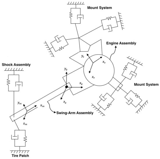
Figure 1.
Powertrain and swing-arm layout [40].
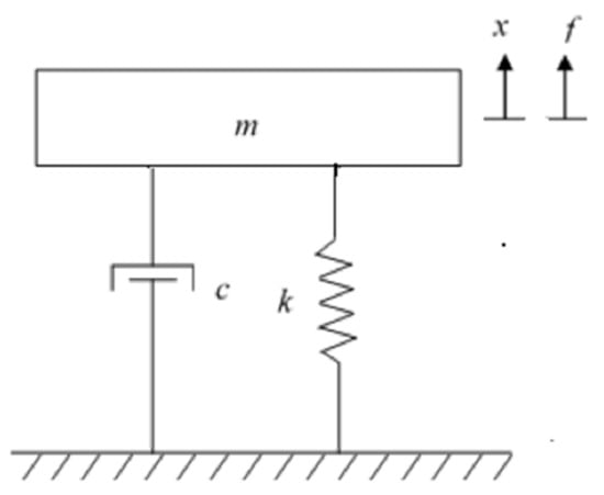
Figure 2.
Schematic diagram of the motorcycle engine mount model.
This section shows the first of two twelve-degree-of-freedom (DOF) models for the motorcycle mounting system, with the first considering the influence of road loads. Road loads must be addressed when building a motorcycle mounting system because of the nature of motorcycles. This ensures the greatest possible handling. In this work, two twelve-DOF motorcycle engine mount models were modified and improved. The first model has twelve degrees of freedom but ignores road loads, whereas the second model has twelve degrees of freedom but takes into consideration both road and shaking loads.
4.1. Model 1: Deriving Matrices for Stiffness and Damping Coefficients
In the model presented herein [40], the equation of motion (EOM) is represented as follows:
For mass, damping, and stiffness, M, C, and K are 12 × 12 matrices. F denotes the input force vector coming from engine imbalance and/or road loads produced by road profile defects. The term is called a harmonic vector in which angular frequency and t is time. X represents both the swing-arm and the powertrain’s displacement vector, which encompasses both translational and rotational DOFs. Equation (2) demonstrates how to represent the vector X.
The subscripts ‘sa’ and ‘e’ in Equation (2) denote the parameters for the wing-arm and powertrain assemblies, respectively. , and represent rotation motion for the wing arm. The same applies for powertrain assemblies where represent translation motion along the x; y; and z axes, and represent rotational motion around the x, y, and z axes. The system’s total mass matrix is calculated as stated in Equation (3) below:
Mengine and Mswingarm are the 6 × 6 mass matrices for the powertrain and swing-arm assemblies, respectively. Z6 is a 6 × 6 zero matrix as a result.
The wing-arm and engine mass matrices are equivalent, and they are defined as shown in Equation (4). The inertia matrices for the engine and swing-arm are set at their respective local centers of gravity.
The stiffness matrix for the 12-DOF system is determined in Equation (5), whereas the damping matrix is defined in Equation (6):
Ke and Kse and Ce and Csa are the stiffness and damping matrices for the powertrain and swing-arm, respectively, in Equations (5) and (6). The stiffness characteristics of the two rear shock springs linking the swing-arm to the frame are used to create the swing-arm’s stiffness matrix. The coupler’s stiffness and damping matrices, Kc and Cc, are both 6 × 6.
The frame is indefinitely stiff in this model. This assumption implies that the connection points between the engine mounts and the frame, as well as the frame and the rear suspension, exhibit zero deflection.
Two situations will be discussed using the EOM formulation introduced in the previous section. The first example addresses the engine’s shaking forces as they are communicated to the frame (Model 1). The second scenario examines the loads sent to the frame by shaking forces, as well as the loads transmitted to the frame by the road (Model 2).
4.2. Model 1: Shaking Forces
In Equation (7), the shaking force vector is a 6 × 1 vector. It is worth noting that the shaking force vector development is for a 45°-bank angle V-twin engine.
The overall shaking forces of the V-twin engine are shown in Equations (8) and (9)
The corresponding masses at distances r1 and r2 for the left and right banks are mcb1 and mcb2, respectively, in the previous formulae.
In Equations (10) and (11) below, the overall shaking moments for the V-twin engine are articulated:
The shaking torque is expressed in Equation (12).
where r is the crank length, , mB is the equivalent rotating mass, and β is the bank angle.
4.3. Model 2: Shaking Forces and Road Loads (Combined Loads)
Both shaking forces related to imbalance inside the engine and loads due to irregularities in the road profile are considered in the model given here. Model 1 shows the governing equations for shacking loads. Through the tire patch, road loads are passed to the frame. The road loads that are transmitted to the frame might be either periodic or nonperiodic. The frequency content of these loads is determined using Fourier Transforms [21] after they are evaluated for specified displacement functions. Fast Fourier Transforms (FFT) in MATLAB were employed in this study. The loads are calculated using Equation (13) for a certain road profile.
In Equation (13), Fy is the vertical force component that is transmitted through the tire patch due to displacement x and the velocity generated from the road profile. k and c are the respective stiffness and damping of the rear wheel in the y-direction.
The continuous time Fourier series (CTFS) for a periodic function is expressed in the equation below:
In the above equation, cm is the Fourier series coefficients that are determined as follows:
P is the fundamental period of the displacement function, which corresponds to the fundamental frequency ωo, as shown in Equation (14). The discrete time Fourier series (DTFS) is written as
where and cmd are the Fourier series coefficients that are determined using the following equation:
In Equations (16) and (17), the sample period is denoted by T. Equation (18) is used to derive the DTFS coefficients. When a restricted band displacement function is used and a suitable sample frequency is set using FFT, the following results are obtained:
The continuous time Fourier transform (CTFT) of the displacement function is shown in Equation (19), and the discrete time Fourier transform (DTFT) is expressed in Equation (20) below:
In Equations (19) and (20), X(ω) is the spectrum of x(t) that can be used for periodic and non-periodic displacement functions.
The optimization problem for the model presented in Figure 2 is solved using a swarm intelligence optimization method (GWO), an evolutionary algorithm (GA), and a local optimization algorithm known as Sequential Quadratic Programming (SQP). The objective function is designed to lower transmitted forces while also considering the engine displacement constraints imposed by static and dynamic loads.
4.4. Formulation of the Optimization Problems
The cost function used in this study is the weighted total of the transmitted force through each individual mount. The shaking loads inside the engine generate the transmitted forces through the mounts. The force that each individual mount exerts on the frame is calculated as follows:
Xti and Xri are the translational and rotational displacements at the powertrain’s center of gravity owing to shaking loads, and ri is the skew symmetric from the position vector of the individual mount stated in Equation (1). ki is the individual mount’s local stiffness matrix. The objective function, fw, is obtained by adding the Euclidean norms of the individual forces passed by each mount.
is the weighting parameter in Equation (22) that corresponds to various loading circumstances.
Adding a deflection limitation to the optimization issue determines the maximum permitted engine weight. The static deflection Xst at the origin of the global coordinate system is calculated as follows:
In Equation (23), Fst is the static load on the system.
The engine mount optimization problem can be expressed as follows:
Mount stiffness, location, and orientation, , represent the design parameters in Equation (24) that are subjected to a total of N constraints . The problem has boundary constraints on the engine mount stiffness, constraints on the mount placement based on available space, symmetry requirements on the mount orientation, and lastly a constraint on the powertrain’s center of gravity deformation owing to static weight. The objective function is defined by Equation (22). Both fw and, are functions of the design parameters, .
5. Results and Discussion
In this section, the optimization findings are reported and discussed. The results of the optimization algorithms are exhibited and compared to each other to demonstrate that swarm intelligence optimization algorithms can effectively and reliably tackle highly non-linear optimization problems and complicated engineering challenges. Most notably, the two 12-DOF models’ optimal design variables were successfully determined, and the transmitted force from the body/frame to the engine, and vice versa, was minimized. Mechanical vibrations were thus isolated and/or reduced.
Each method undergoes a total of five computational optimization experiments to guarantee that appropriate and dependable results are obtained. In addition to the tolerance given in the method, the maximum number of iterations is set to 1000 iterations as a stopping condition for these algorithms. Table 1 lists the parameters for the GWO, GA, and SQP algorithms. Table 2 shows the engine mount’s optimum design variables, as well as their upper and lower bounds. The achieved design optimization results for the first model, which solely addresses shaking loads, are shown in Table 3 and Table 4. The achieved design optimization results for the second model that includes the combined loads are shown in Table 5 and Table 6 (shaking and road loads).

Table 1.
The set parameters of the employed algorithms.
Table 2.
Upper and lower bounds of the design variables.
Table 3.
Optimized mounts’ stiffness (12-DOF model—shaking loads only).
Table 4.
Optimization results of natural frequencies (12-DOF model—shaking loads only).
Table 5.
Optimization results of damping coefficients (12-DOF model—shaking loads only).
Table 6.
Optimized mounts’ position and orientation (12-DOF model—shaking loads only).
The decoupled vibration modes for the two models utilizing different optimization strategies are shown in Figure 3, Figure 4, Figure 5, Figure 6, Figure 7, Figure 8, Figure 9, Figure 10 and Figure 11. It is accomplished by minimizing the global stiffness matrix’s off-diagonal terms. We guarantee that the diagonal stiffness matrix terms are the only dominant ones by doing so. This will ensure that the powertrain’s rolling motion is kept to a minimum. At lower frequency values, vibration modes are not decoupled as intended. Meanwhile, the vibration modes are cleaner, i.e., when the vibration frequency is higher, and decoupling occurs as shown in Figure 3, Figure 4, Figure 5, Figure 6, Figure 7 and Figure 8 for model 1 (shaking loads only) and Figure 9, Figure 10, Figure 11, Figure 12, Figure 13 and Figure 14 for model 2 (combined loading).
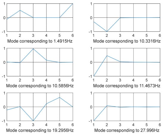
Figure 3.
GWO-optimized mode shapes 1–6 (12-DOF model—shaking loads only).
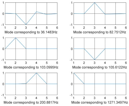
Figure 4.
GWO-optimized mode shapes 7–12 (12-DOF model—shaking loads only).
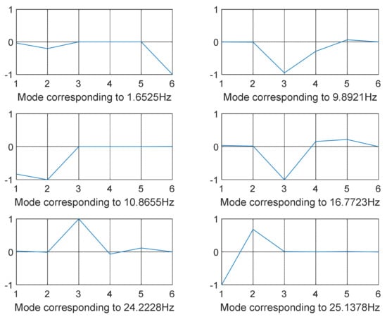
Figure 5.
GA-optimized mode shapes 1–6 (12-DOF model—shaking loads only).
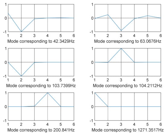
Figure 6.
GA-optimized mode shapes 7–12 (12-DOF model—shaking loads only).
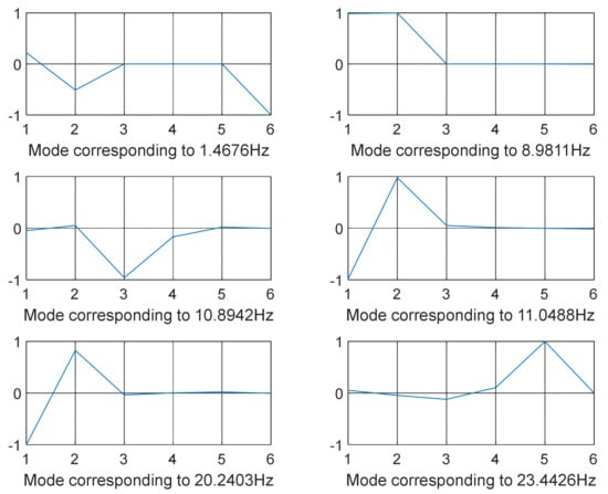
Figure 7.
SQP-optimized mode shapes 1–6 (12-DOF model—shaking loads only).
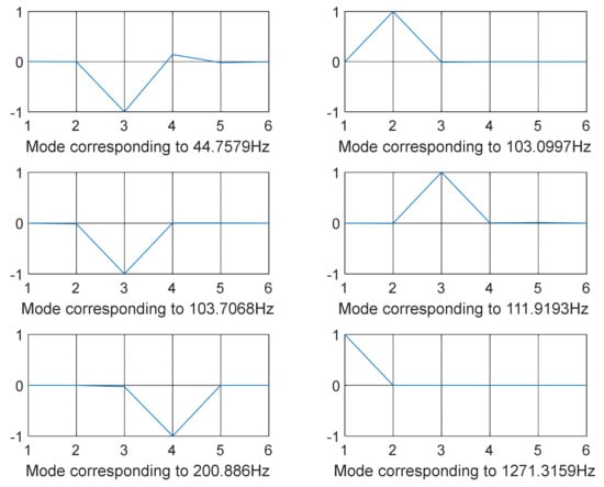
Figure 8.
SQP-optimized mode shapes 7–12 (12-DOF model—shaking loads only.
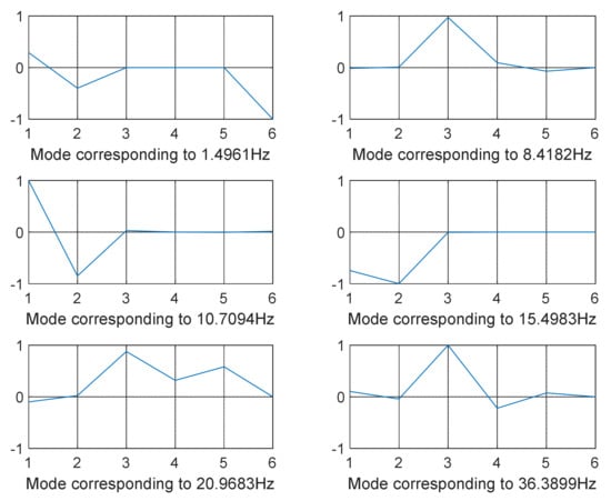
Figure 9.
GWO-optimized mode shapes 1–6 (12-DOF model—combined loading).
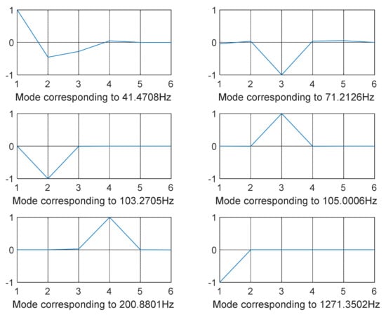
Figure 10.
GWO-optimized mode shapes 7–12 (12-DOF model—combined loading).
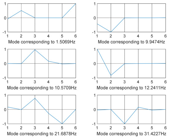
Figure 11.
GA-optimized mode shapes 1–6 (12-DOF model—combined loading).
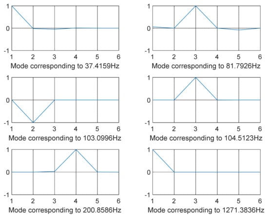
Figure 12.
GA-optimized mode shapes 7–12 (12-DOF model—combined loading).
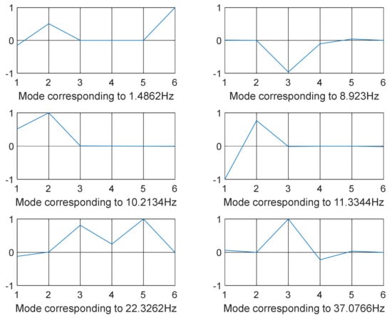
Figure 13.
SQP-optimized mode shapes 1–6 (12-DOF model—combined loading).
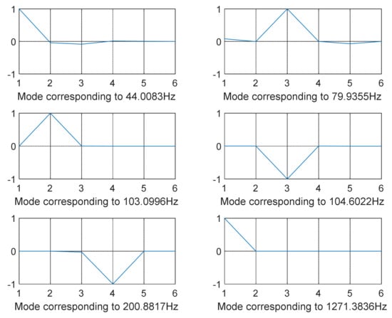
Figure 14.
SQP-optimized mode shapes 7–12 (12-DOF model–combined loading).
The modes were not totally separated for low-vibration frequencies, as shown in Figure 3 and Figure 4 specifically when the frequency was in the range of 0–100 Hz except for few shapes where even at low frequency decoupling occurred Figure 3 (mode shape at frequency 10.3316 Hz) and Figure 5 (mode shape at frequency 25.1378 Hz). GA and SQP were also successful in decoupling the modes of vibration but at high computational cost and not forgetting the values of the transmitted force that were not optimal compared to those obtained by GWO.
The best design variables and objective function for the 12-DOF model considering solely the shaking loads are shown in Table 3, Table 4 and Table 5. Table 3 reports the optimized mount stiffness along each axis. Table 4 and Table 5 report the damped and un-damped natural frequencies and damping coefficients, respectively. Table 6 reports the optimized mounts’ position and orientation where the engine mounts at these positions and orientations largely contribute towards minimizing transmitted forces and isolating mechanical vibrations considering shaking loads only. Likewise, Table 7, Table 8 and Table 9 report the optimal design variables, optimized objective function, and mount stiffness along each axis for the 12-DOF model when considering the combined shaking loads and road forces for various optimization strategies. Table 10 reports the optimized mounts’ position and orientation considering combined loads. It is worth noting that because the goal function values are directly proportional to the design variables, the lower objective function values indicate a better overall isolation system. Lower damping and stiffness values, on the other hand, will aid in accomplishing this goal. The amount of damping and stiffness of a vehicle has a direct impact on its handling and maneuverability. High damping and stiffness rates can result in low vibration transmission at low frequencies, resulting in poor performance at higher frequencies. Low damping and stiffness rates, on the other hand, will result in low noise but significant vibration transmission. Finding the best damping and stiffness parameters for the engine mounts can assist in reducing vibration transmission without sacrificing handling and agility. The GWO method, as shown in Table 3 and Table 7, delivers the lowest values of the objective function, i.e., transmitted loads. The related values of the improved design variables, such as mount stiffness, position, and orientation, are shown in Table 3 and Table 6 when only shaking loads are considered and in Table 7 and Table 10 when combined loading is considered.
Table 7.
Optimized mounts’ stiffness (12-DOF model—combined loading).
Table 8.
Optimization results of natural frequencies (12-DOF model—combined loading).
Table 9.
Optimization results of damping coefficients (12-DOF model—combined loading).
Table 10.
Optimization results for mounts’ positions and orientations (12-DOF model—combined loading).
After around 100 iterations, GWO converged to the global optimum solution, which was significantly less than the 1000 iterations chosen as the stopping condition. This demonstrates that GWO had a fast convergence rate for this particular application PMS, which means less computing time and expense, as well as optimum outcomes with limited computational resources. The outcomes of the PMS application demonstrate GWO’s exploration ability.
The convergence characteristics of the first PMS model, which only includes shaking loads, are shown in Figure 15 and Figure 16. In terms of convergence speed, GWO outperformed GA and SQP, needing less computational time, iterations, and function evaluations. It also shows that GWO discovered the finest global minima.
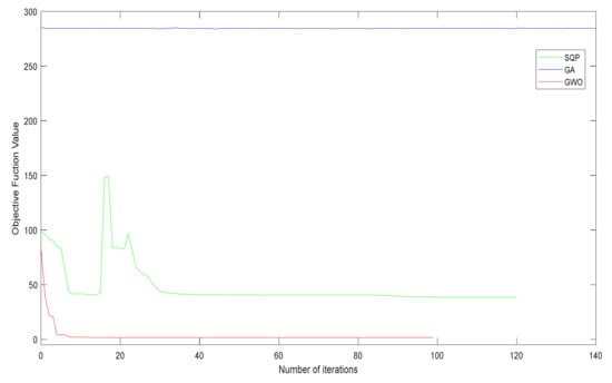
Figure 15.
Convergence characteristics of the optimization algorithms used for the 12-DOF model (shaking loads only).
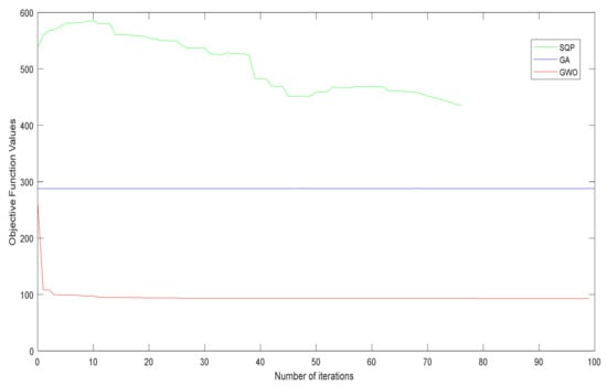
Figure 16.
Convergence characteristics of the optimization algorithms used for the 12-DOF model (combined loading).
GWO achieved a minimal value of 1.5981 lb. for the objective function, minimizing the transmitted load, compared to 285.5898 lb. and 38.7022 lb. for GA and SQP, respectively. The transmitted force from the engine to the framework was minimized for model 1 (including only shaking loads) and was found to be 1.5981 lb., 285.5898 lb., and 38.7022 lb. using GWO, GA, and SQP, respectively. As can be observed in Figure 17, GWO obtained the optimal and least transmitted force value of 1.5981 lb., as opposed to the high values obtained by GA and SQP. A similar scenario can be seen for the other model, model 2 (combined loading), where GWO obtained the smallest (optimal) transmitted force of 92.9407 lb. compared to 288.0116 lb. and 434.3781 lb. using GA and SQP, respectively, as shown in Figure 18.
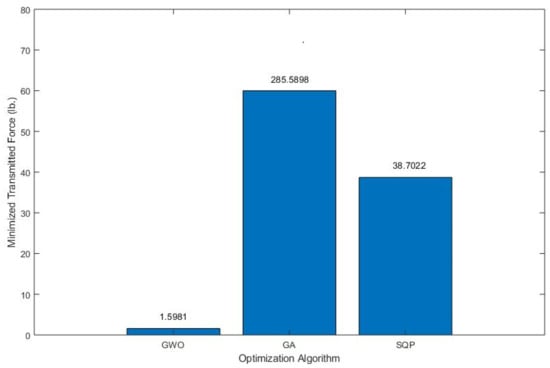
Figure 17.
Minimized transmitted force for the 12-DOF model (shaking loads only).
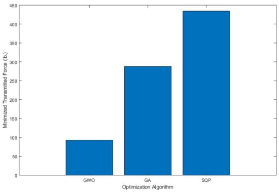
Figure 18.
Minimized transmitted force for the 12-DOF model (combined loading).
In contrast to GA and SQP, GWO smoothly and precisely converged to a global optimal solution, as illustrated in Figure 15. For the proposed PMS model, this reflects the efficiency and resilience of the swarm intelligence optimization algorithm. The convergence characteristics of the second PMS model when combined loads (shaking and road loads) are considered are shown in Figure 16. Even though this is a complex model, GWO outperformed GA and SQP. As shown in Figure 16, even the beginning of the search in GWO was better than the optimum to which GA and SQP converged. GWO’s capacity to handle complex PMS design optimization models is demonstrated in this way. When swarm intelligence optimization techniques are applied to complex PMS models, the computing cost is reduced, and the outcomes are improved.
It is worth mentioning that GA did not work well on MPS models since the objective function value did not change much over many iterations, as seen in Figure 15 and Figure 16. In other words, new generations and children do not appear to have made much progress. The SQP convergence trend shows that the algorithm has trouble finding a global best solution. In both Figure 15 and Figure 16, the objective function evaluation did not smoothly converge from high to low values, but rather traveled up and down until it reached what the algorithm believed is a global optimum. This is because SQP is a local search method, and the best solution (which could be local or global) is determined by the search beginning point. In [41], the authors gave a performance comparison of GA, SQP, and other evolutionary and swarm optimization techniques.
Figure 17 and Figure 18 show that GWO performed better than the GA and SQP algorithms in terms of the amount of transmitted force for both 12-DOF models, the first model that considers only shaking loads and the second model that considers the combined loads. GWO was able to minimize the transmitted loads to 1.5981 lb. while GA and SQP did not do well compared to GWO and produced a transmitted load of 285.58 lb. (the worst) and 38.7002 lb., respectively. When considering combined loads, GWO outperformed GA and SQP as can be seen in Figure 18. GWO minimized the shaking and road loads and transmitted about 92.94 lbs. to the motorcycle frame compared to GA (transmitted 288 lbs.) and SQP, which was the worst in this loading case (transmitted 434 lbs.). It can be concluded that GWO did very well for both models by minimizing and isolating mechanical vibrations.
Finally, GO surpassed the competition in terms of PMS design optimization, as well as being more resilient and less costly in terms of CPU costs. The results of GWO were positive, highlighting the importance of swarm intelligence algorithms in MPS design and optimization. On the other hand, different optimization techniques such as GA and SQP may perform well in other technological applications. As a result, the engineering problem determines the optimization algorithm. In MPS applications, GWO was better than MPS; however, it may not be as effective in other engineering applications.
6. Conclusions
This paper investigated and optimized two 12-DOF PMS models. The first model considers only shaking loads, while the second model considers both shaking loads and road loads. The purpose of this work was to determine optimal PMS design parameters that minimize the loads induced by shaking forces, which eventually isolate mechanical vibrations. Stiffness, position, and orientation of the engine mounts were considered to be design parameters. The optimal design parameters that minimize the selected objective function of both models were determined using low-cost swarm intelligence and evolutionary optimization approaches. The implemented optimization approaches were successful in capturing vibration isolation qualities and producing appropriate PMS design parameters. Based on the findings of this study, swarm intelligence optimization approaches such as GWO have been shown to be promising in sophisticated and extensive computation engineering applications such as PMS. The transmitted force from the engine to the framework was minimized for model 1 (including only shaking loads) and found to be 1.5981 lb., 285.5898 lb., and 38.7022 lb. using GWO, GA, and SQP, respectively. Compared to GA’s and SQP’s high values, GWO had the ideal and least transmitted force value of 1.5981 lb. For the other model, model 2 (combined loading), the transmitted force obtained by GWO was 92.9407 lb., which was the smallest (optimal) when compared to 288.0116 lb. and 434.3781 lb. using GA and SQP, respectively. A comparison of the optimization algorithms utilized in this work revealed GWO’s superior performance. In comparison to GA and SQP, GWO successfully decoupled vibration modes at high frequencies with less computational cost. GWO demonstrated improved performance in terms of reducing the transmitted force values from the engine to the frame and decoupling vibration modes at a reduced computational cost. Based on the simulation and computational findings for this particular application PMS, GWO was the best in terms of convergence speed, accuracy, and computing cost.
Author Contributions
Conceptualization, A.Y., F.A. and Z.D.; methodology, A.Y.; software, A.Y.; validation, A.Y., F.A. and Z.D.; formal analysis, A.Y.; investigation, A.Y.; resources, A.Y., F.A. and Z.D.; data curation, A.Y. and F.A.; writing—original draft preparation, A.Y.; writing—review and editing, Z.D.; visualization, A.Y.; supervision, Z.D.; project administration, A.Y. All authors have read and agreed to the published version of the manuscript.
Funding
This research received no external funding.
Institutional Review Board Statement
Not applicable.
Informed Consent Statement
Not applicable.
Data Availability Statement
Not applicable.
Conflicts of Interest
The authors declare no conflict of interest.
References
- Stefano, A.; Natale, B.A. Investigation of Structural Motorcycle Vibrations Due to Engine; Omniscriptum Gmbh & Co., Kg.: Saarbrücken, Germany, 2015; ISBN 978-3639659429. [Google Scholar]
- Scappaticci, L.; Bartolini, N.; Guglielmino, E.; Risitano, G. Structural optimization of a motorcycle chassis by pattern search algorithm. Eng. Optim. 2017, 49, 1373–1387. [Google Scholar] [CrossRef]
- Johnson, S.; Subhedar, J. Computer Optimization of Engine Mounting Systems. SAE Technical Paper 790974; In 3rd International Conference on Vehicle Structural Mechanics; SAE International: Warrendale, PA, USA, 1979. [Google Scholar] [CrossRef]
- Arai, T.; Kubozuka, T.; Gray, S. Development of an Engine Mount Optimization Method Using Modal Parameters. In SAE 1993 Transactions: Journal of Passenger Cars-V102-61993; SAE Technical Paper 932898; SAE International: Warrendale, PA, USA, 1993. [Google Scholar] [CrossRef]
- Heyns, S. An Optimization Approach to Engine Mounting Design; SPIE—The International Society for Optical Engineering: Bellingham, WA, USA, January 1996. [Google Scholar]
- Foumani, M.S.; Khajepour, A.; Durali, M. Optimization of Engine Mount Characteristics Using Experimental/Numerical Analysis. J. Control. Vib. 2003, 9, 1103–1120. [Google Scholar] [CrossRef]
- Kaul, S.; Dhingra, A.K.; Hunter, T.G. Two approaches for optimum design of motorcycle engine mount systems. J. Eng. Optim. 2005, 37, 307–324. [Google Scholar] [CrossRef]
- Courteille, E.; Mortier, F.; Leotoing, L.; Ragneau, E. Multi-objective robust design optimization of an engine mounting system. In Proceedings of the SAE 2005 Noise and Vibration Conference and Exhibition, Traverse City, MI, USA, 16 May 2005. [Google Scholar]
- Kaul, S.; Anoop, D.; Timothy, H. Frame Flexibility Effects on Engine Mount Optimization for Vibration Isolation in Motorcycles. J. Vib. Acoust. 2007, 129, 590–600. [Google Scholar] [CrossRef]
- Kaul, S.; Dhingra, A.K. Engine mount optimization for vibration isolation in motorcycles. Veh. Syst. Dyn. 2009, 47, 419–436. [Google Scholar] [CrossRef]
- Nariman-Zadeh, N.; Salehpour, M.; Jamali, A. Pareto optimization of a five-degree of freedom vehicle vibration model using a multi-objective uniform-diversity genetic algorithm (MUGA). Eng. Appl. Artif. Intel. 2010, 23, 543–551. [Google Scholar] [CrossRef]
- Cheli, F.; Pezzola, M.; Agostoni, S.; Giombini, M. Methodology to optimize engine mounts design in order to minimize inertial unbalances vibration propagation. In Proceedings of the 2011 19th Mediterranean Conference on Control & Automation (MED), Corfu, Greece, 20–23 June 2011. [Google Scholar]
- Ooi, L.; Ripin, Z.M. Optimization of an engine mounting system with consideration of frequency-dependent stiffness and loss factor. J. Vib. Control 2016, 22, 2406–2419. [Google Scholar] [CrossRef]
- Ahn, Y.K.; Kim, Y.C.; Yan, B.S.; Ahmadian, M.; Ahn, K.K.; Morishita, S. Optimal Design of an Engine Mount Using an Enhanced Genetic Algorithm with Simplex Method. Veh. Syst. Dyn. 2005, 431, 57–81. [Google Scholar] [CrossRef]
- Ayarani-N, M.H.; Yao, X.; Xu, H. Meta-heuristic algorithms in car engine design: A literature survey. IEEE Trans. Evol. Comput. 2015, 19, 609–629. [Google Scholar] [CrossRef]
- Ganguly, A.; Bhatia, N.; Agarwal, V.; Mohite, U. Balancing Optimization of a Motorcycle Engine Crankshaft for Vibration Reduction; SAE Technical Paper 2016-01-1060; SAE International: Warrendale, PA, USA, 2016. [Google Scholar] [CrossRef]
- AlKhatib, F.; Dhingra, A. Vibration analysis, shape and design of motorcycle mounting system subjected to shacking forces. Int. J. Eng. Sci. Res. Technol. 2016, 5, 698–713. [Google Scholar]
- Kirthana, S.; Nizamuddin, M. Finite Element Analysis and Topology Optimization of Engine Mounting Bracket. Mater. Today Proc. 2018, 5, 19277–19283. [Google Scholar] [CrossRef]
- Xu, X.; Su, C.; Dong, P.; Liu, Y.; Wang, S. Optimization design of powertrain mounting system considering vibration analysis of multi-excitation. Adv. Mech. Eng. 2018, 10, 1687814018788246. [Google Scholar] [CrossRef]
- Sleesongsom, S.; Bureerat, S. Vibration Suppression of a Single-Cylinder Engine by Means of Multi-objective Evolutionary Optimization. Sustainability 2018, 10, 2067. [Google Scholar] [CrossRef]
- Ohadi, A.R.; Maghsoodi, G. Simulation of engine vibration on nonlinear hydraulic engine mounts. J. Vib. Acoust. 2007, 129, 417–424. [Google Scholar] [CrossRef]
- Mirjalili, S.; Mirjalili, S.M.; Lewis, A. Grey wolf optimizer. Adv. Eng. Softw. 2014, 69, 46–61. [Google Scholar] [CrossRef]
- Holland, J.H. Adaptation in Natural and Artificial Systems; University of Michigan Press: Ann Arbor, MI, USA, 1975. [Google Scholar]
- Nocedal, J.; Wright, S.J. Numerical Optimization, 2nd ed.; Springer: New York, NY, USA, 2006; ISBN 978-0-387-30303-1. [Google Scholar]
- Yang, X.S. Nature-Inspired Metaheuristic Algorithms; Luniver Press: Frome, UK, 2008; ISBN 978-1-905986-10-1. [Google Scholar]
- Kennedy, J.; Eberhart, R.C. Particle swarm optimization. In Proceedings of the IEEE International Conference on Neural Networks, Perth, Australia, 27 November–1 December 1995. [Google Scholar]
- Yang, X.-S.; Deb, S. Cuckoo Search via Levy Flights. In Proceedings of the World Congress on Nature Biologically Inspired Computing, NaBIC 2009, Coimbatore, India, 9–11 December 2009; pp. 210–214. [Google Scholar]
- Dorigo, M.; Birattari, M. Ant colony optimization. IEEE Comput. Intell. Mag. 2006, 1, 28–39. [Google Scholar] [CrossRef]
- Dervis, K. An Idea Based on Honeybee Swarm for Numerical Optimization; Technical Report-TR06; Erciyes University, Computer Engineering Department: Kayseri, Türkiye, 2005. [Google Scholar]
- Karaboga, D.; Basturk, B. A powerful and efficient algorithm for numerical function optimization: Artificial bee colony (ABC) algorithm. J. Glob. Optim. 2007, 39, 459–471. [Google Scholar] [CrossRef]
- Yildiz, A.R.; Abderazek, H.; Mirjalili, S. A Comparative Study of Recent Non-traditional Methods for Mechanical Design Optimization. Arch. Comput. Methods Eng. 2020, 27, 1031–1048. [Google Scholar] [CrossRef]
- Mirjalili, S. Moth-flame optimization algorithm: A novel nature-inspired heuristic paradigm. Knowl. Based Syst. 2015, 89, 228–249. [Google Scholar] [CrossRef]
- Mirjalili, S. The ant lion optimizer. Adv. Eng. Softw. 2015, 83, 80–98. [Google Scholar] [CrossRef]
- Eskandar, H.; Sadollah, A.; Bahreininejad, A.; Hamdi, M. Water cycle algorithm–A novel metaheuristic optimization method for solving constrained engineering optimization problems. Comput. Struct. 2012, 110, 151–166. [Google Scholar] [CrossRef]
- Sadollah, A.; Eskandar, H.; Bahreininejad, A.; Kim, J.H. Water cycle algorithm with evaporation rate for solving constrained and unconstrained optimization problems. Appl. Soft. Comput. 2015, 30, 58–71. [Google Scholar] [CrossRef]
- Sadollah, A.; Bahreininejad, A.; Eskandar, H.; Hamdi, M. Mine blast algorithm for optimization of truss structures with discrete variables. Comput. Struct. 2012, 102, 49–63. [Google Scholar] [CrossRef]
- Mirjalili, S.; Lewis, A. The whale optimization algorithm. Adv. Eng. Softw. 2016, 95, 51–67. [Google Scholar] [CrossRef]
- Mirjalili, S.; Gandomi, A.H.; Mirjalili, S.Z.; Saremi, S.; Faris, H.; Mirjalili, S.M. Salp Swarm Algorithm: A bio-inspired optimizer for engineering design problems. Adv. Eng. Softw. 2017, 114, 163–191. [Google Scholar] [CrossRef]
- Muro, C.; Escobedo, R.; Spector, L.; Coppinger, R. Wolf-pack (Canis lupus) hunting strategies emerge from simple rules in computational simulations. Behav. Process. 2011, 88, 192–197. [Google Scholar] [CrossRef]
- Fadi, A. Techniques for Engine Mount Modeling and Optimization. Ph.D. Thesis, University of Wisconsin Milwaukee, Milwaukee, WI, USA, 2013. [Google Scholar]
- Younis, A.; Dong, Z. Trends, features, and tests of common and recently introduced global optimization methods. Eng. Optim. 2010, 42, 691–718. [Google Scholar] [CrossRef]
Publisher’s Note: MDPI stays neutral with regard to jurisdictional claims in published maps and institutional affiliations. |
© 2022 by the authors. Licensee MDPI, Basel, Switzerland. This article is an open access article distributed under the terms and conditions of the Creative Commons Attribution (CC BY) license (https://creativecommons.org/licenses/by/4.0/).