
Design of Multi-Objective-Based Artificial Intelligence Controller for Wind/Battery-Connected Shunt Active Power Filter


Abstract
:1. Introduction
1.1. Challenges and Motivation
1.2. Literature Review
1.3. Key Contribution
- ⮚
- Design of hybrid controller (NFIHC) involving both the properties of FL and ANN techniques for the WPGS and BS-integrated SHAPF (SH-WPBS).
- ⮚
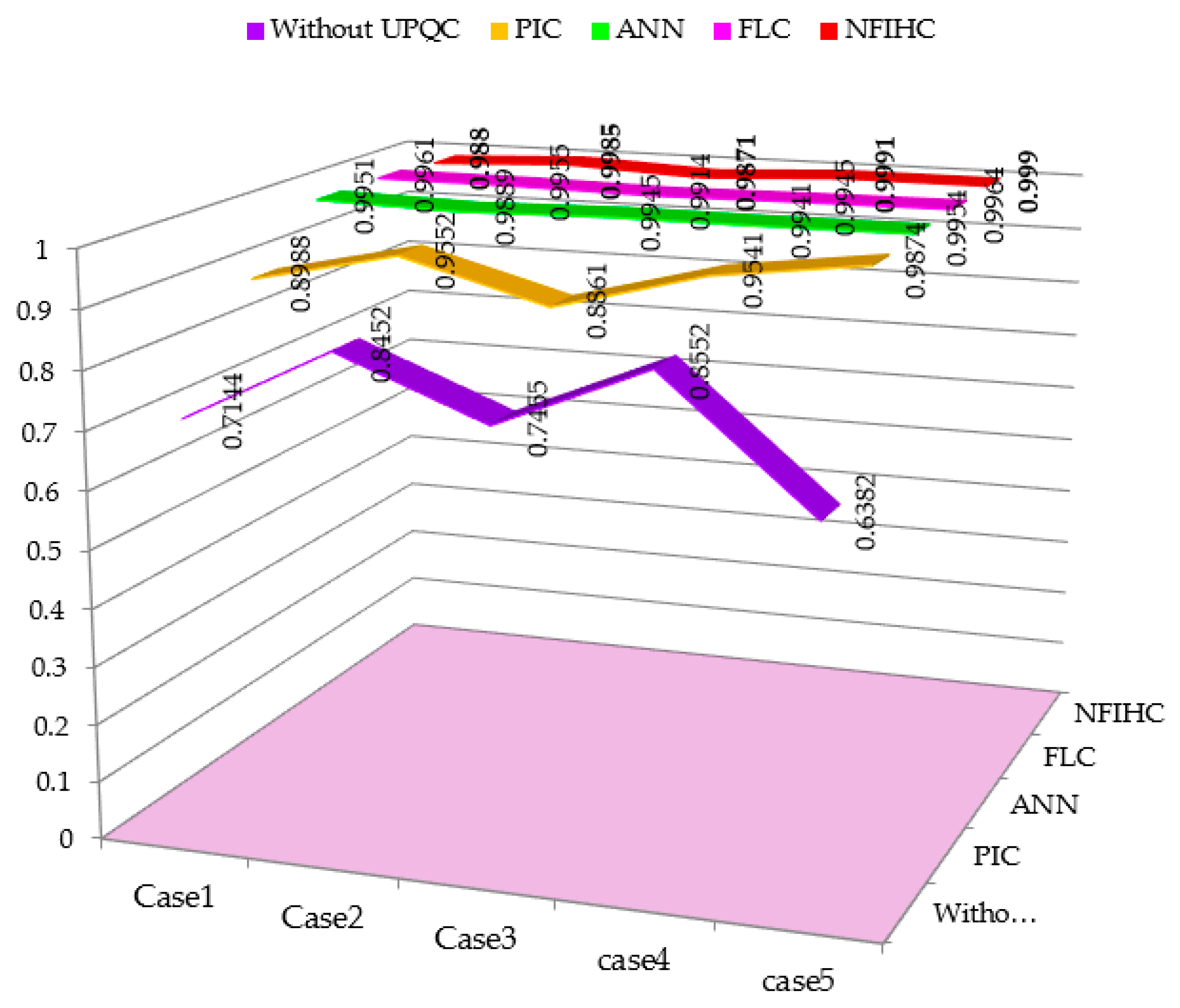
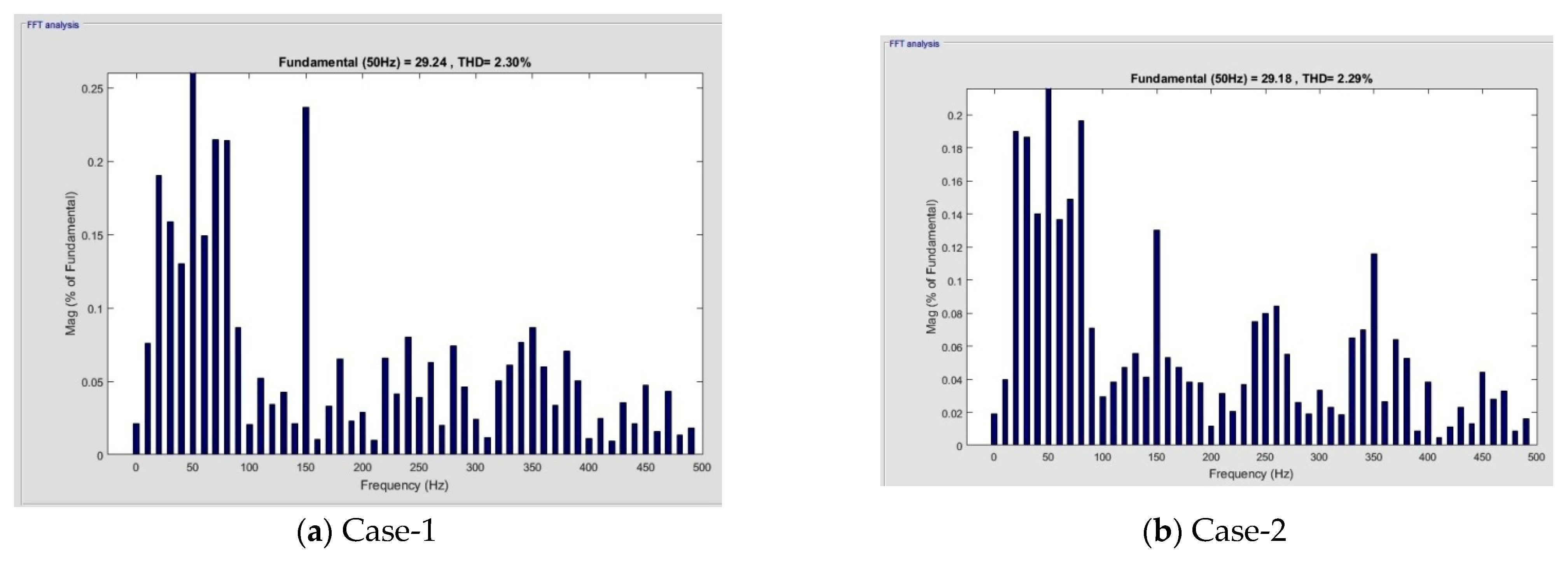
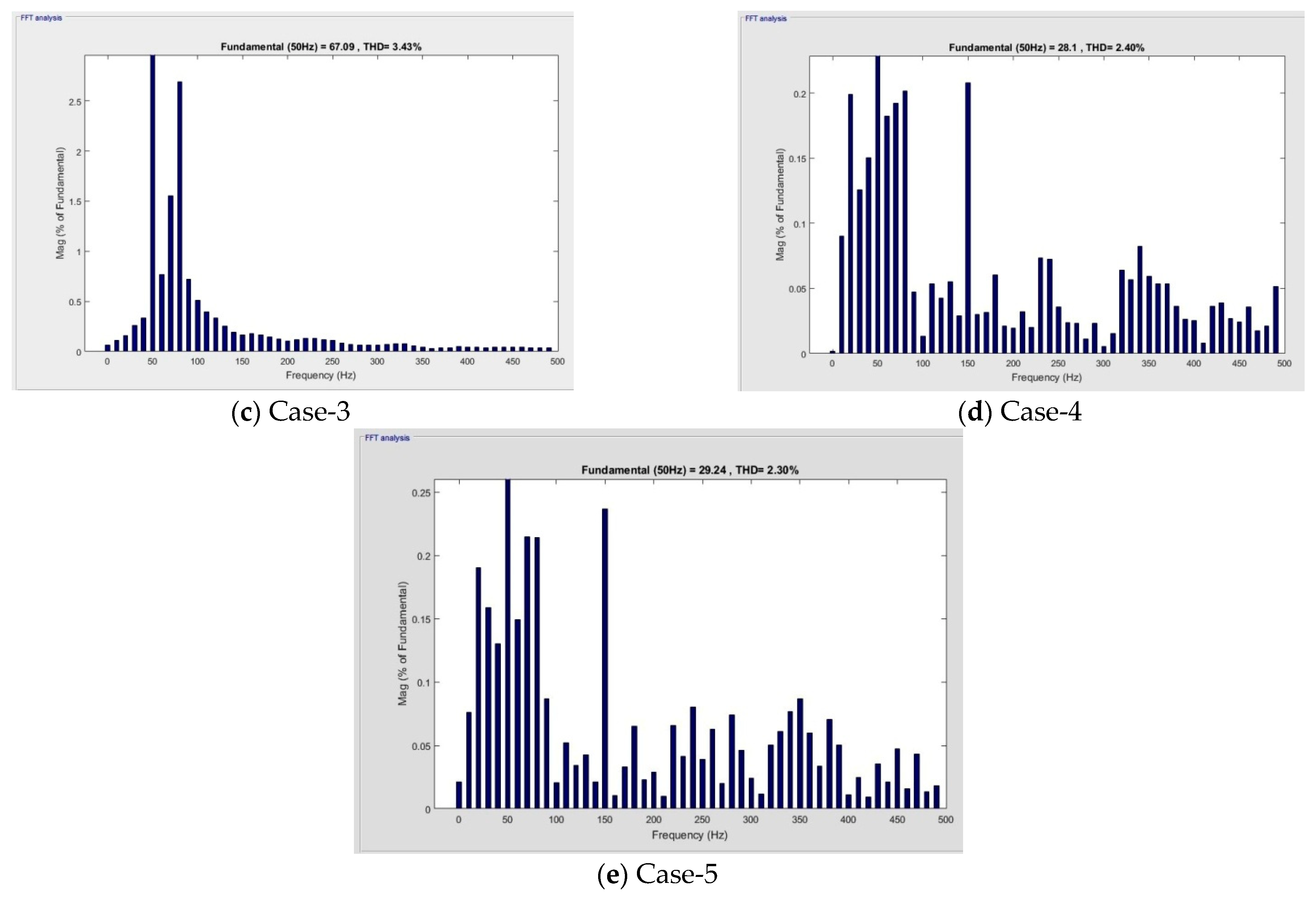
- The prime aim of the proposed method is to minimize THD thereby improving PF and maintaining constant DC-Link voltage.
- ⮚
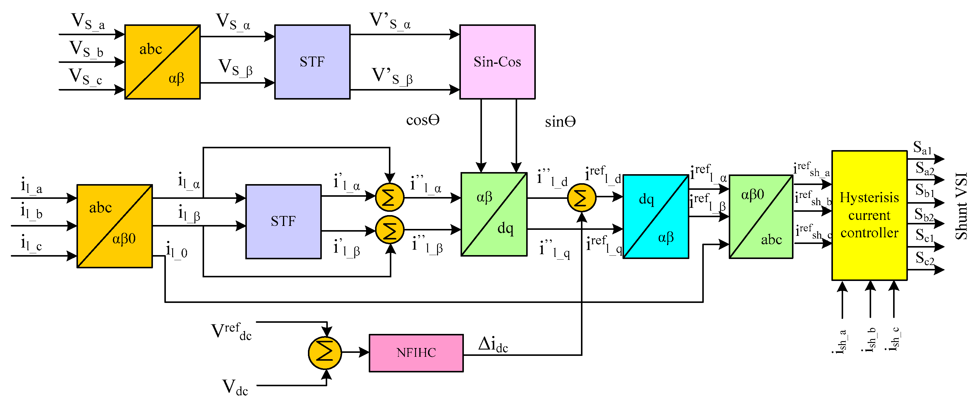
- The proposed STF is used to generate synchronization phases (SYP) for SHAPF instead of PLL. In addition, STF also does the work of LPFs and HPFs for splitting the FC of current.
- ⮚
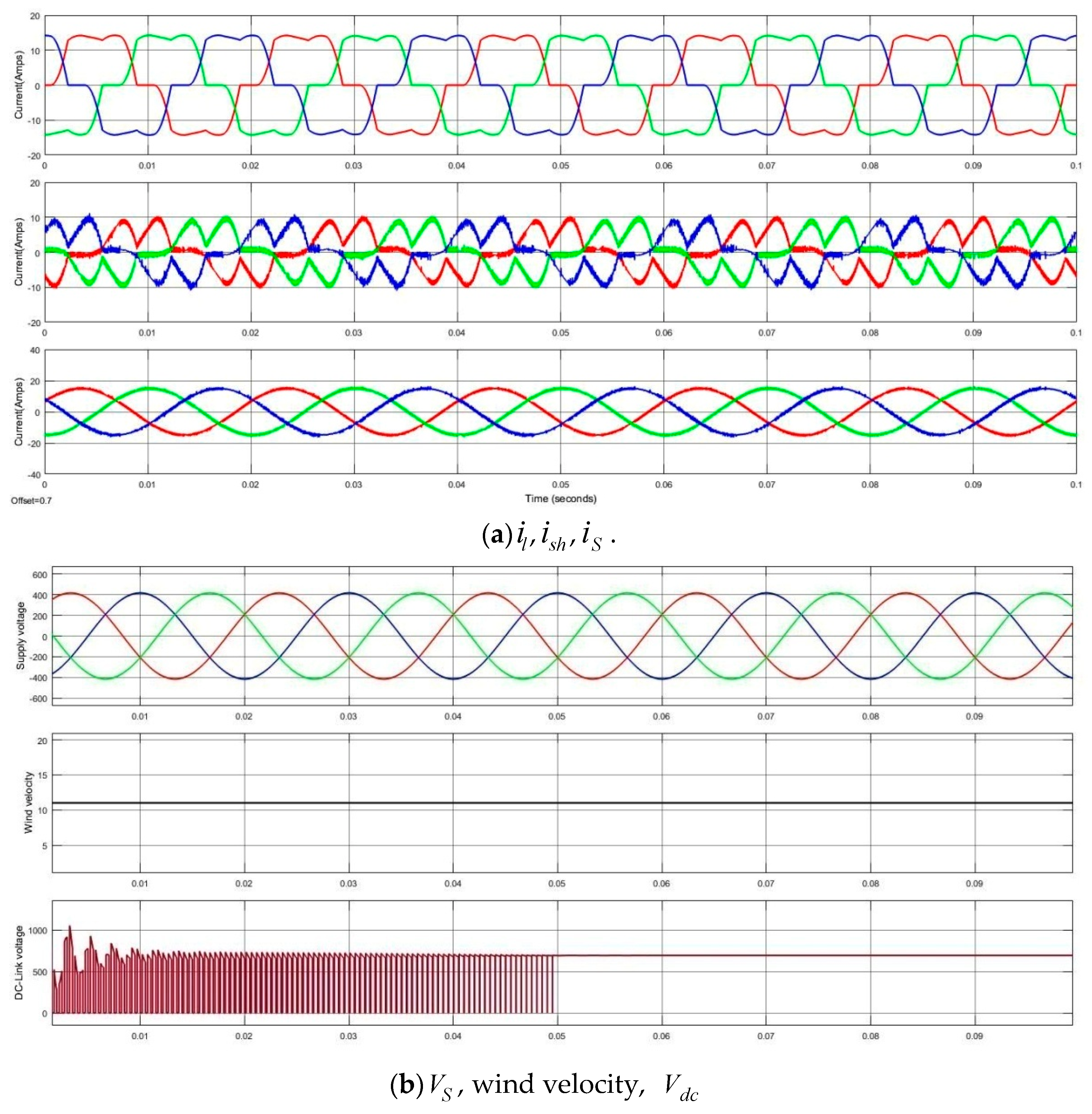
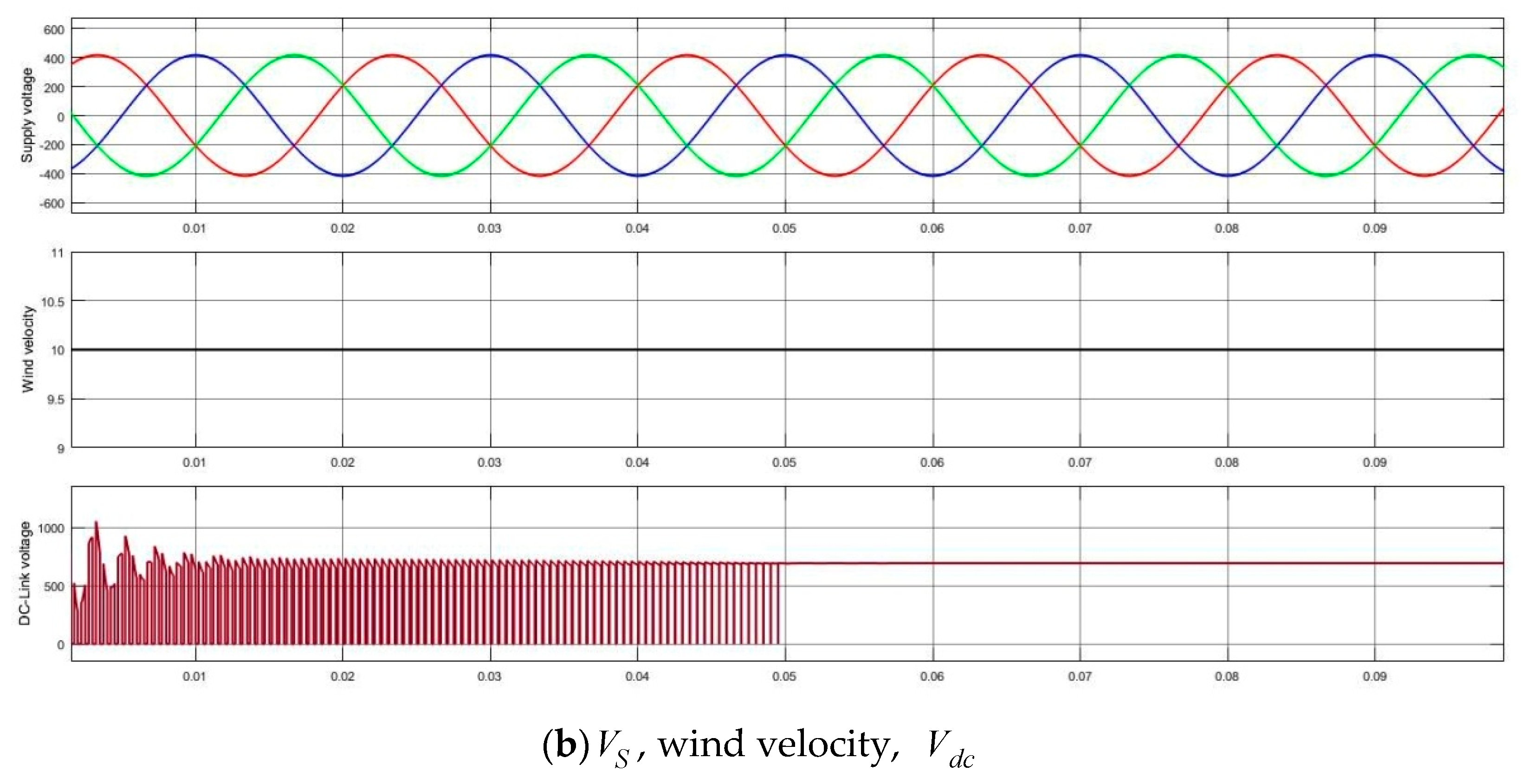
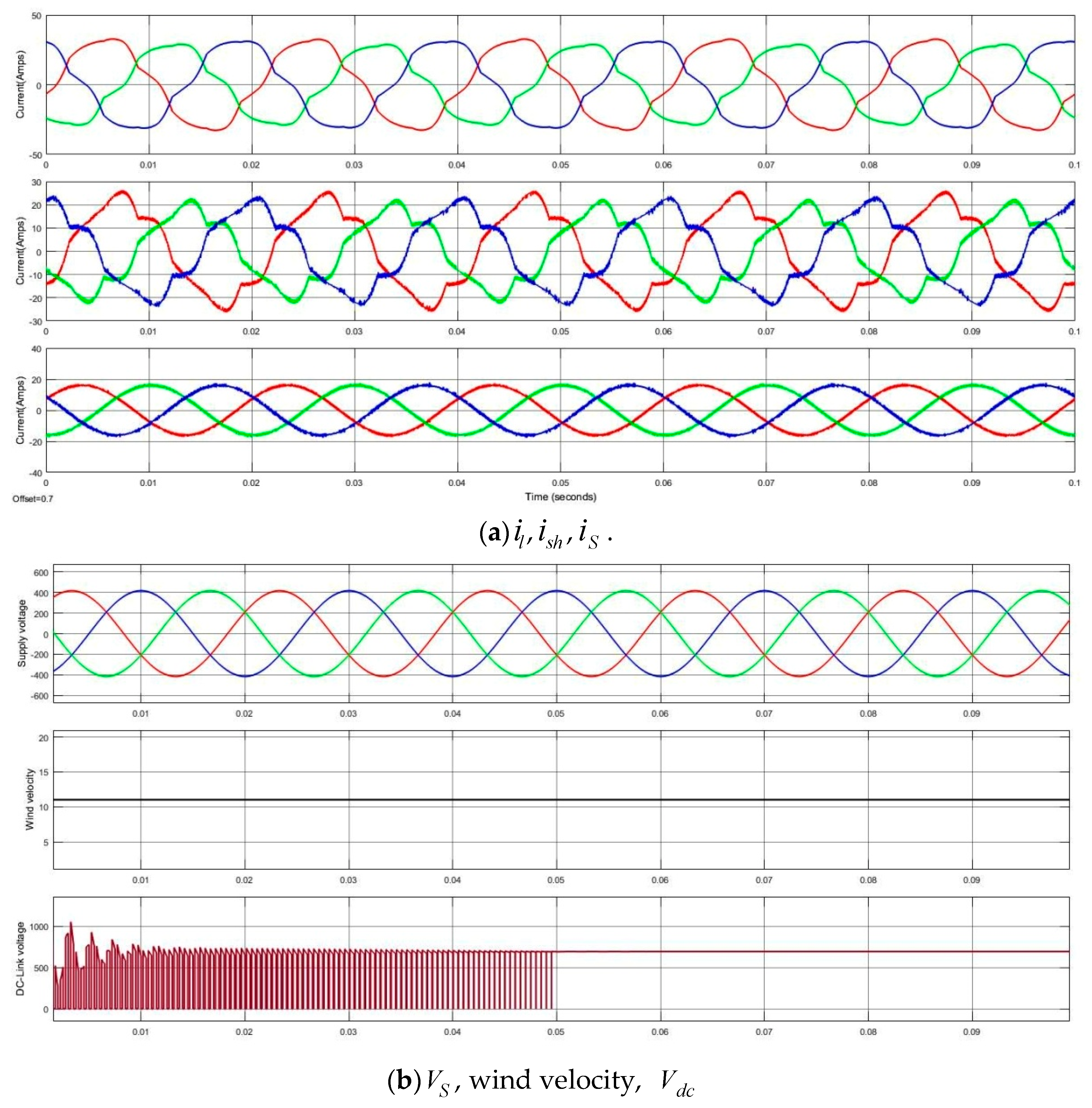
- The results are obtained for variation in loads, distorted supply voltage, and wind uncertainties as case studies.
- ⮚
- Future performance analysis was carried out with PI, FL, and ANN controllers. To exhibit the superiority of the proposed technique, validation was done with those existing methods that are available in the literature.
1.4. Paper Organization
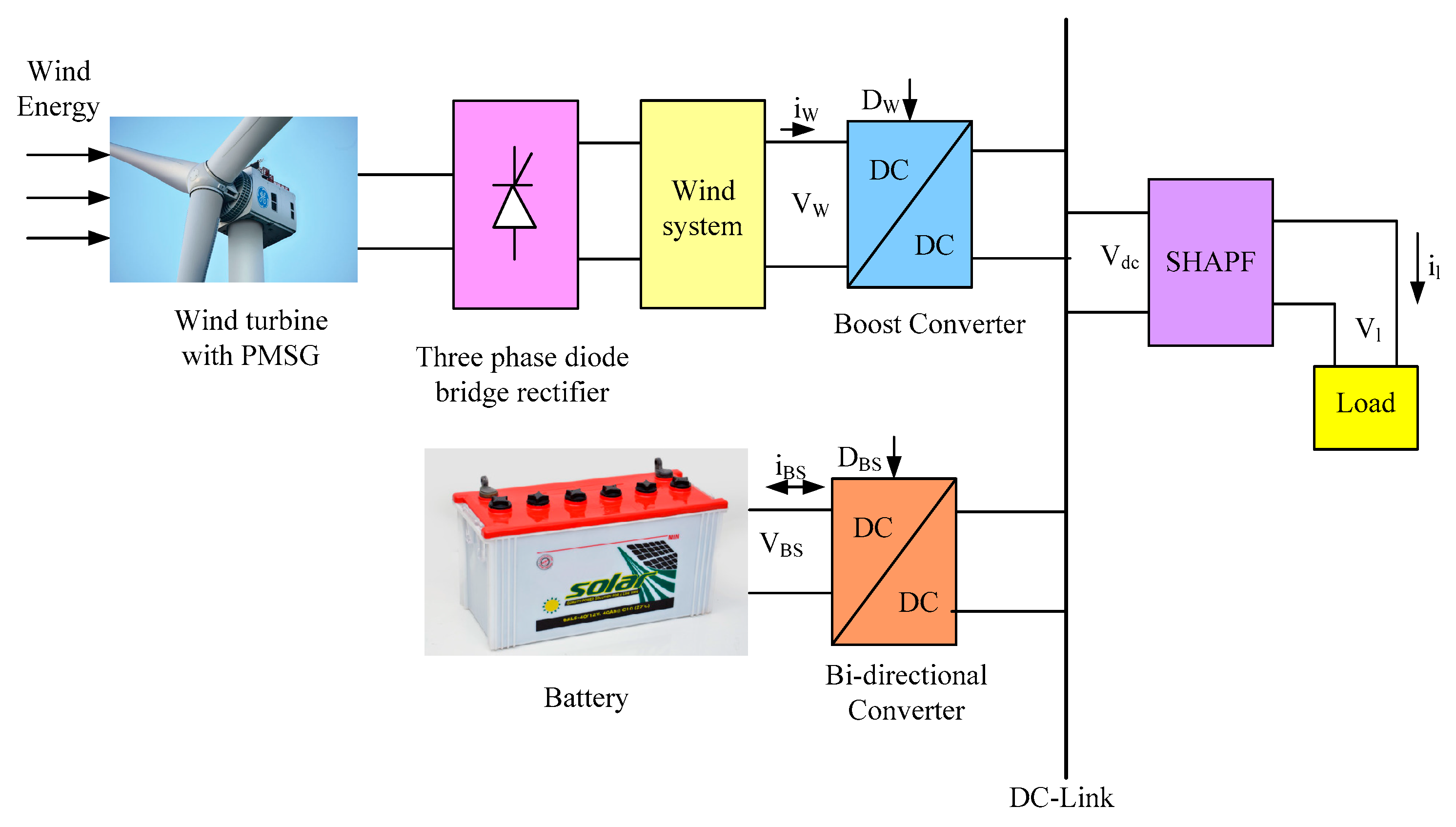
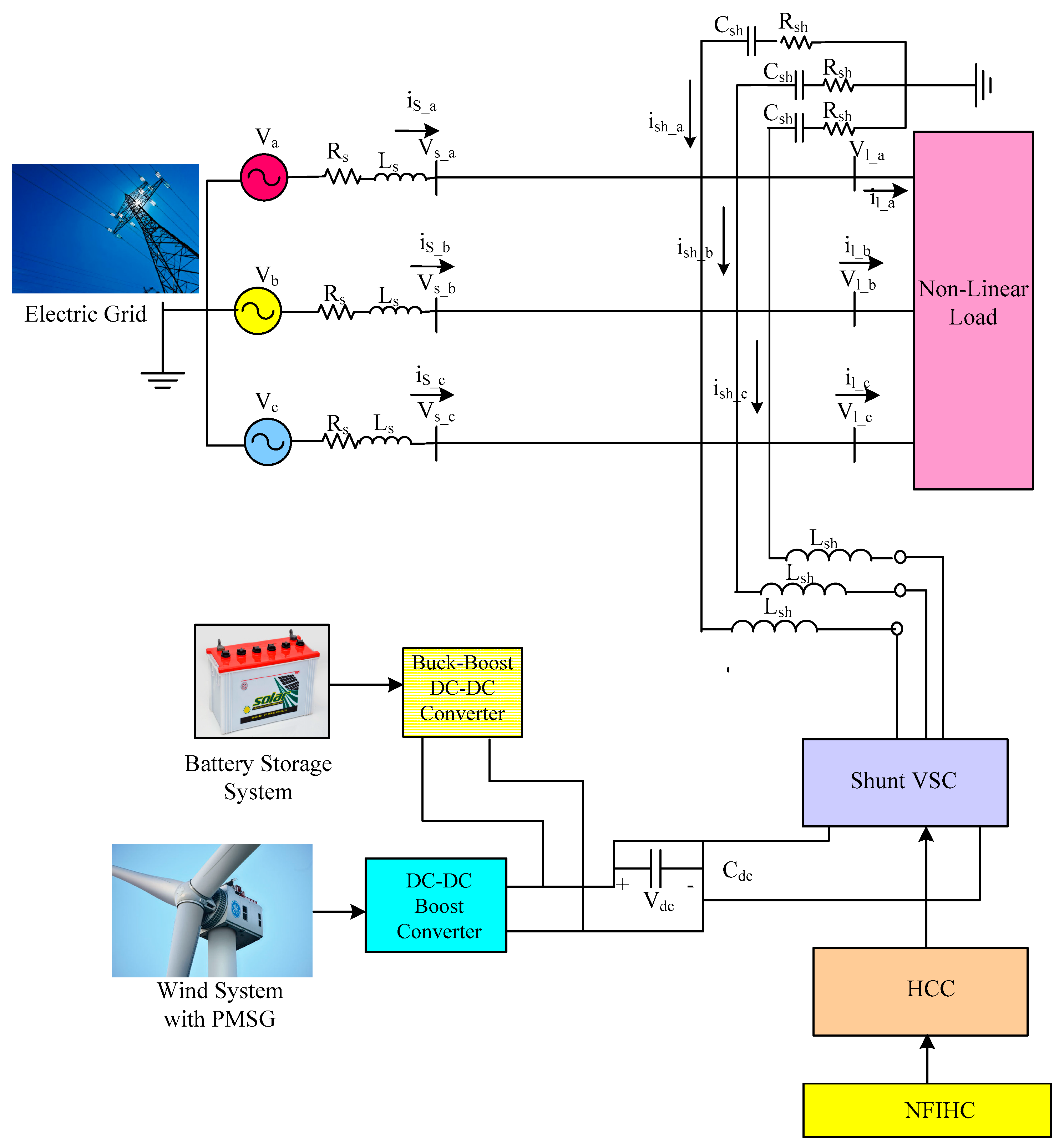
2. Proposed SH-WPBS
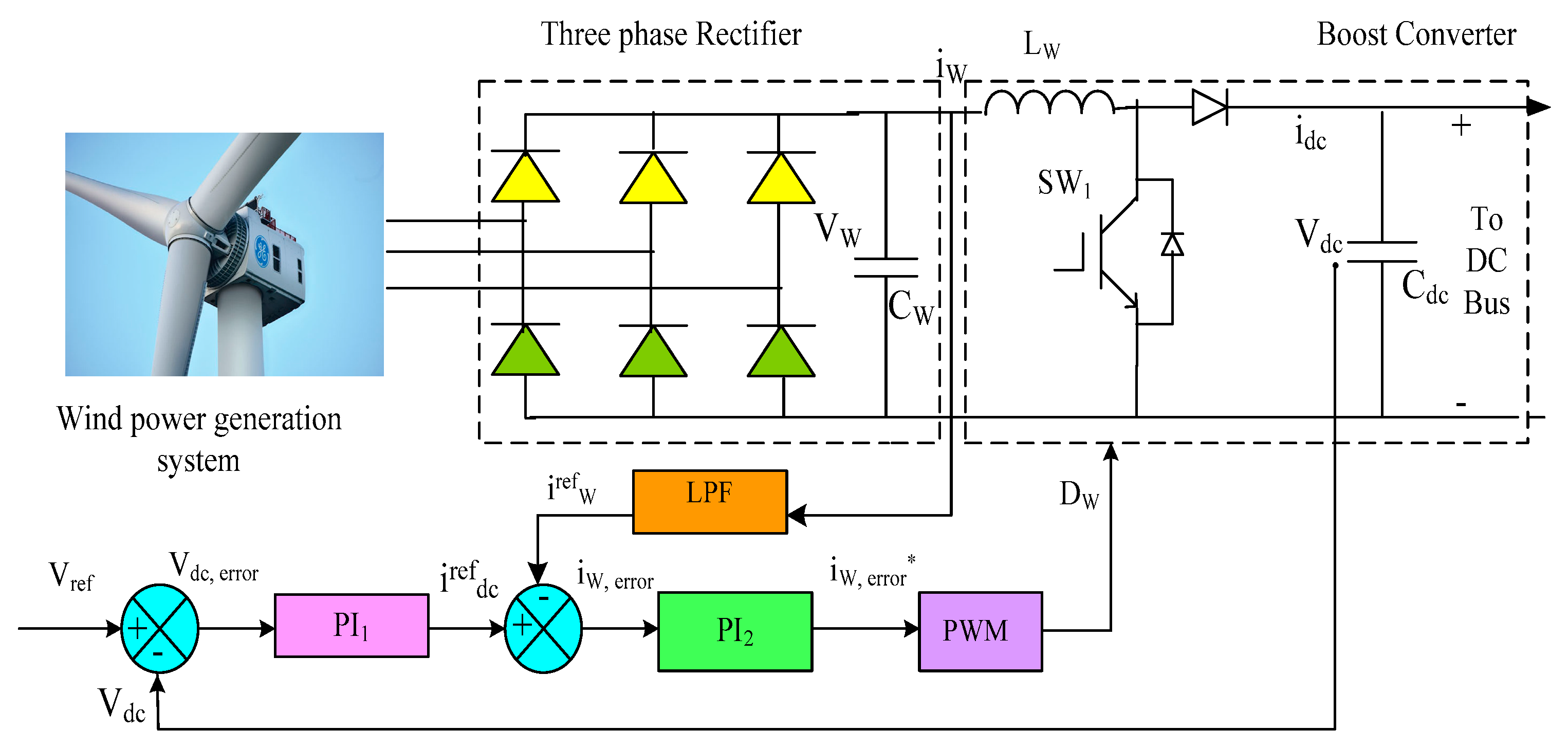
2.1. Wind Power Generation System (WPGS)
- is the density of air in kg/m3
- is the area under swept by the rotor turbine blades in m2
- is the velocity of the wind in m/s
- is the coefficient of power, function of (TSR, ) and pitch-angle ().
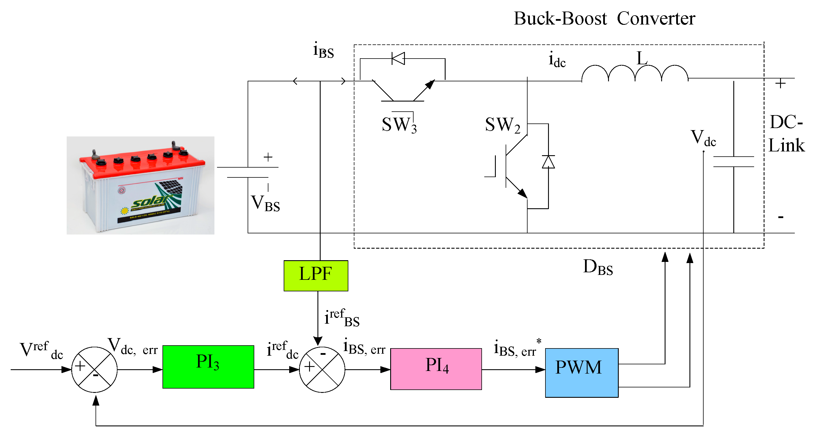
2.2. Battery Storage (BS)
3. Control Strategy
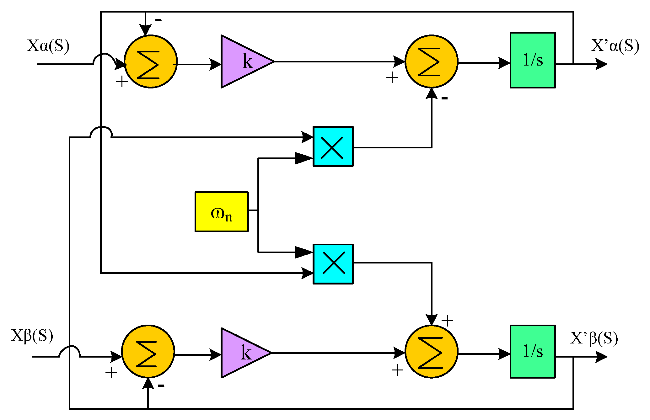
3.1. Modelling of STF
3.2. SHAPF
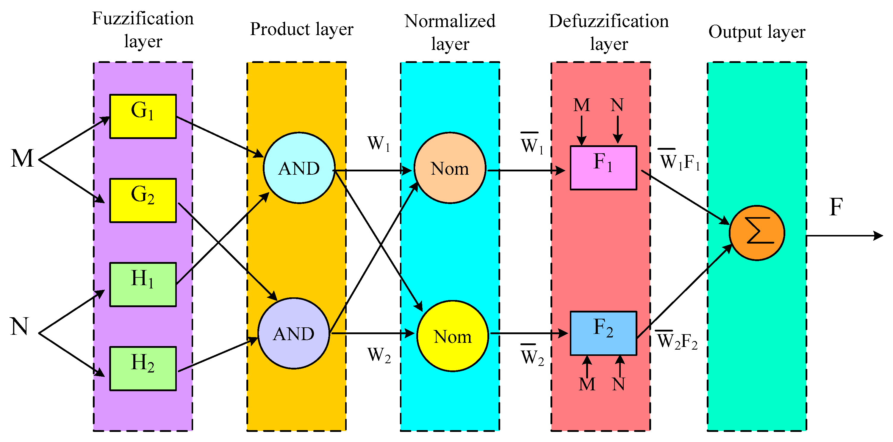
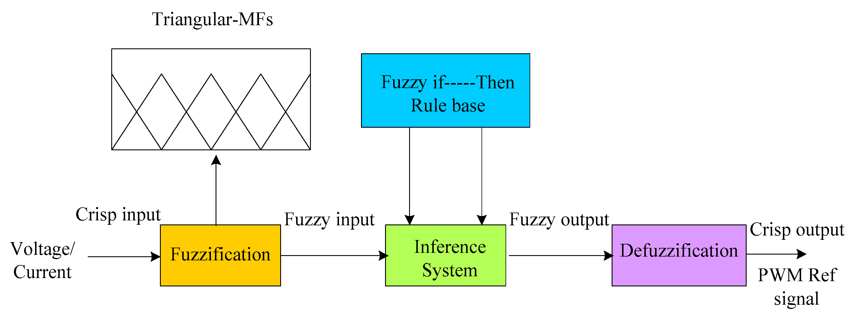
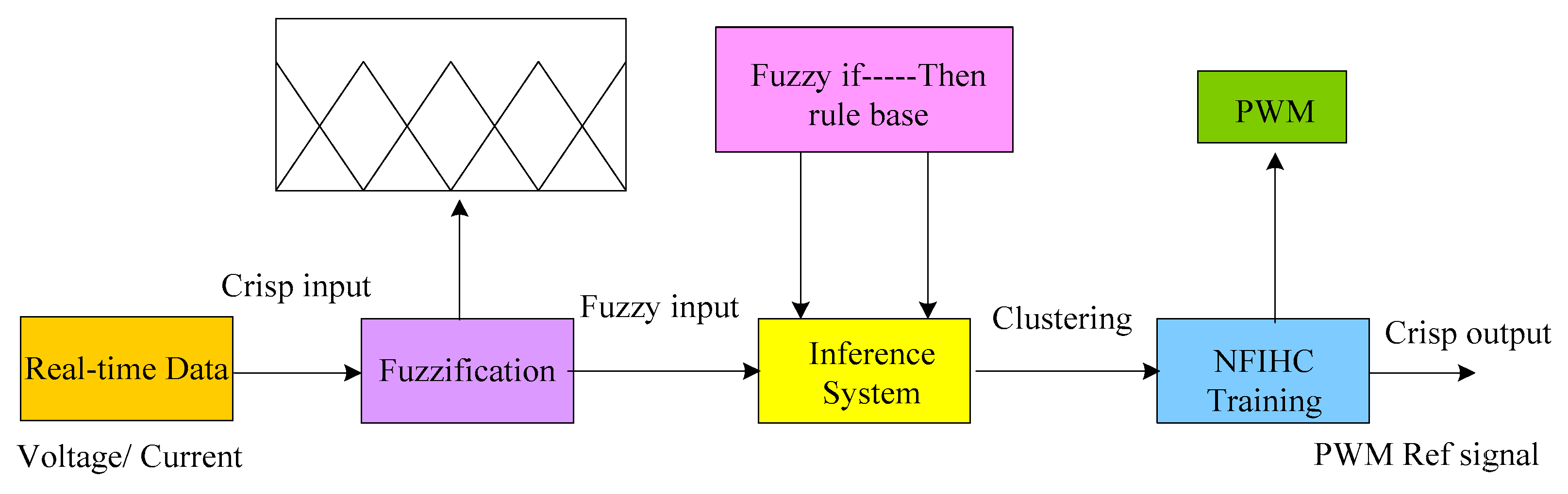
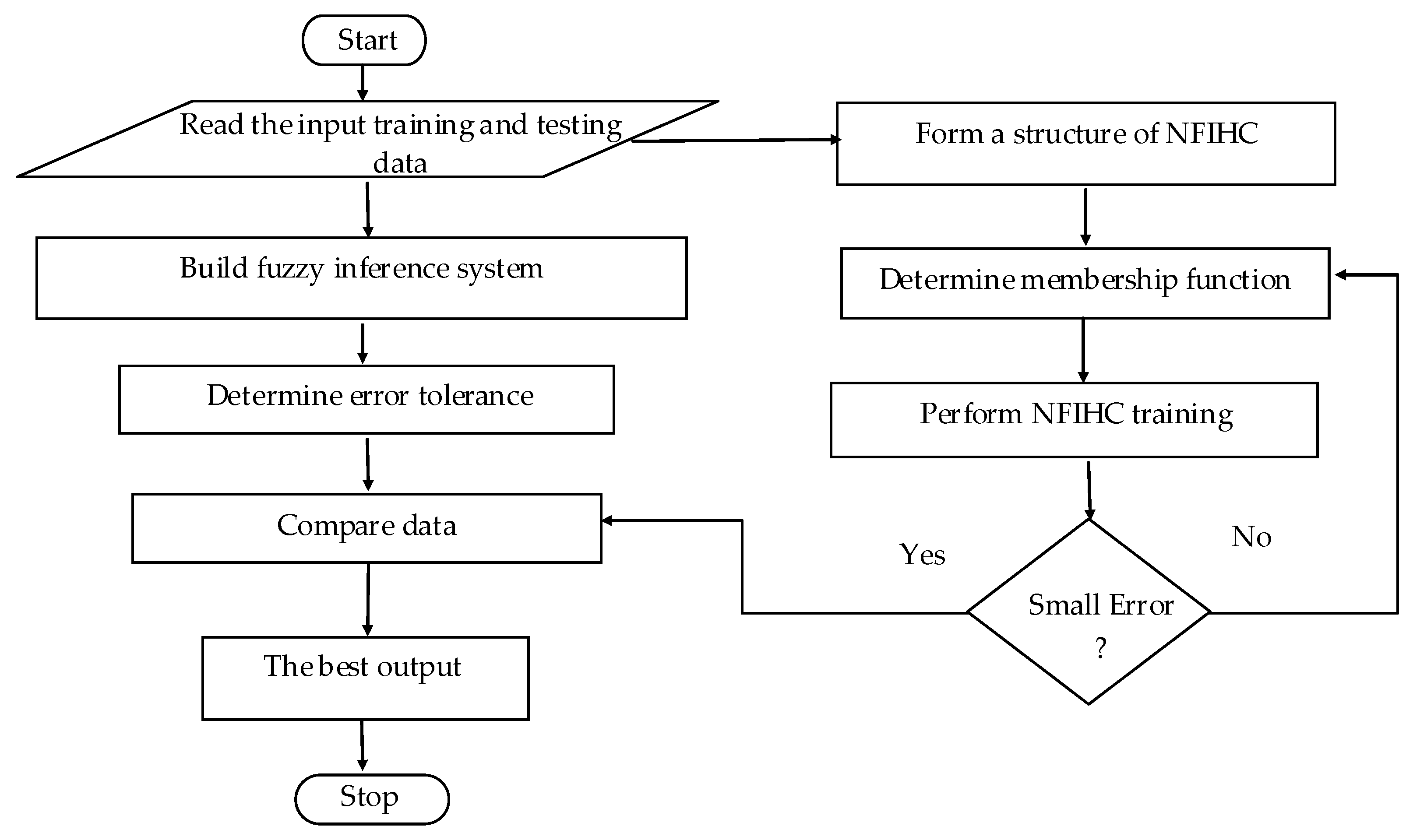
Proposed NFIHC
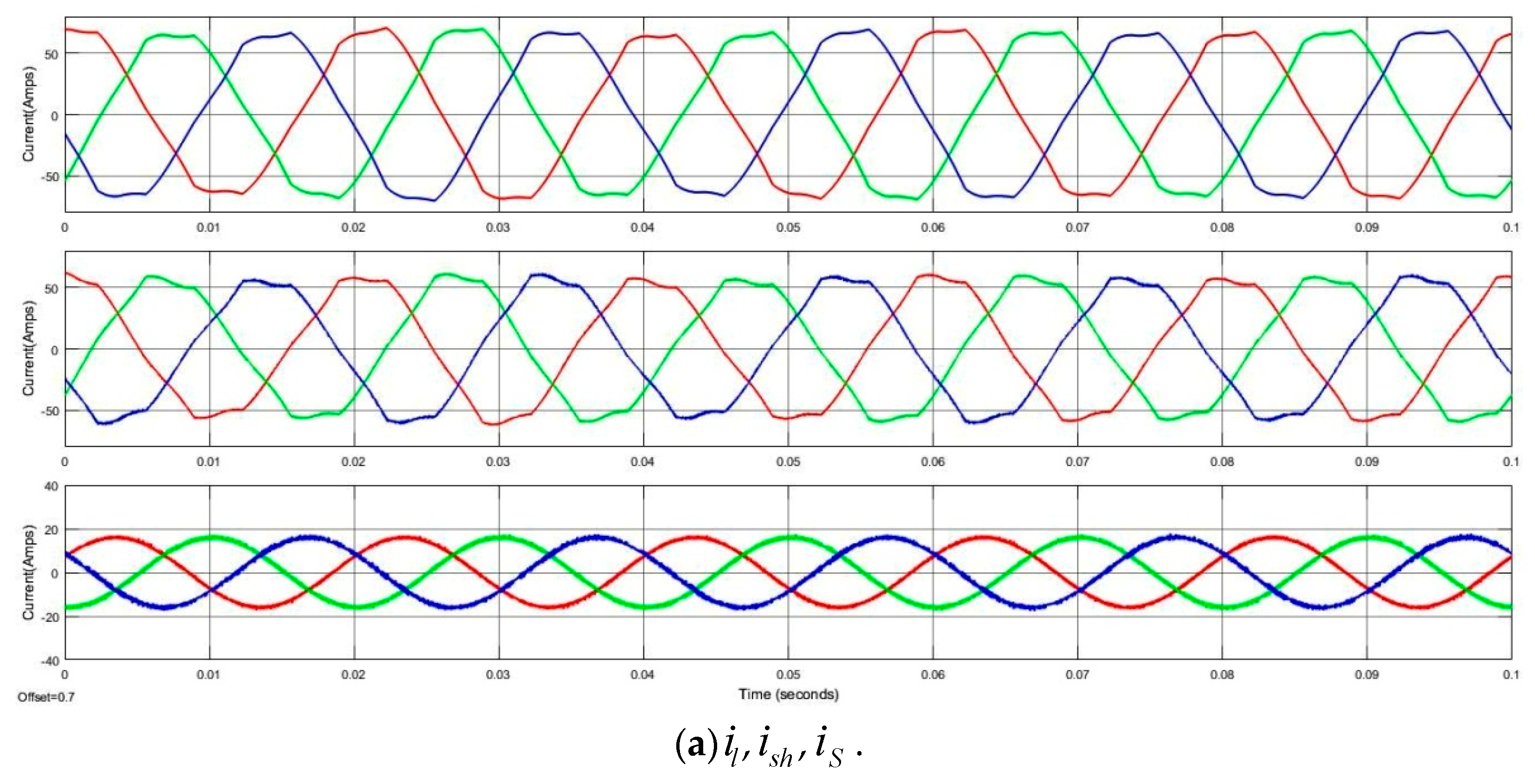
4. Simulation Results and Discussion
5. Conclusions
Author Contributions
Funding
Institutional Review Board Statement
Informed Consent Statement
Data Availability Statement
Conflicts of Interest
Nomenclature
| Source voltage for phases a, b, c | |
| Source voltage in -- domain | |
| FC of source voltage in -- domain | |
| Source current for phases a, b, c | |
| Source Resistance | |
| Source Inductance | |
| Load voltage for phases a, b, c | |
| Load current for phases a, b, c | |
| Load currents in -- domain | |
| FC of load currents in -- domain | |
| HC of load currents in -- domain | |
| HC of load currents in - domain | |
| Reference load current for phases abc | |
| Reference load current -- domain | |
| Reference load current in - domain | |
| SHAPF-injected current for phases a, b, c | |
| Reference SHAPF injected current for phases abc | |
| Capacitance of SHAPF | |
| Resistance of SHAPF | |
| Inductance of SHAPF | |
| DC-Link capacitance | |
| Actual DC-Link capacitor voltage | |
| DC-Link reference voltage | |
| Dc link error | |
| Wind output power | |
| Wind output voltage | |
| Wind output current | |
| Power demand at DC-Link | |
| Battery rated capacity | |
| Battery output voltage | |
| Battery output current | |
| DPD | DC-Link power demand |
| MFs | Membership Functions |
| IPL | Input-layer |
| HDL | Hidden-layer |
| OPL | Output-layer |
| state-of-charge | |
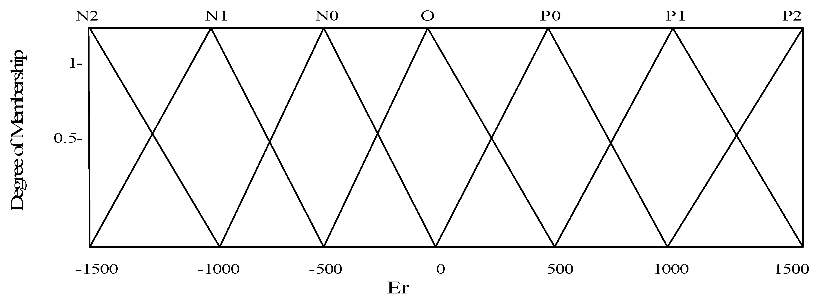
| Error | |
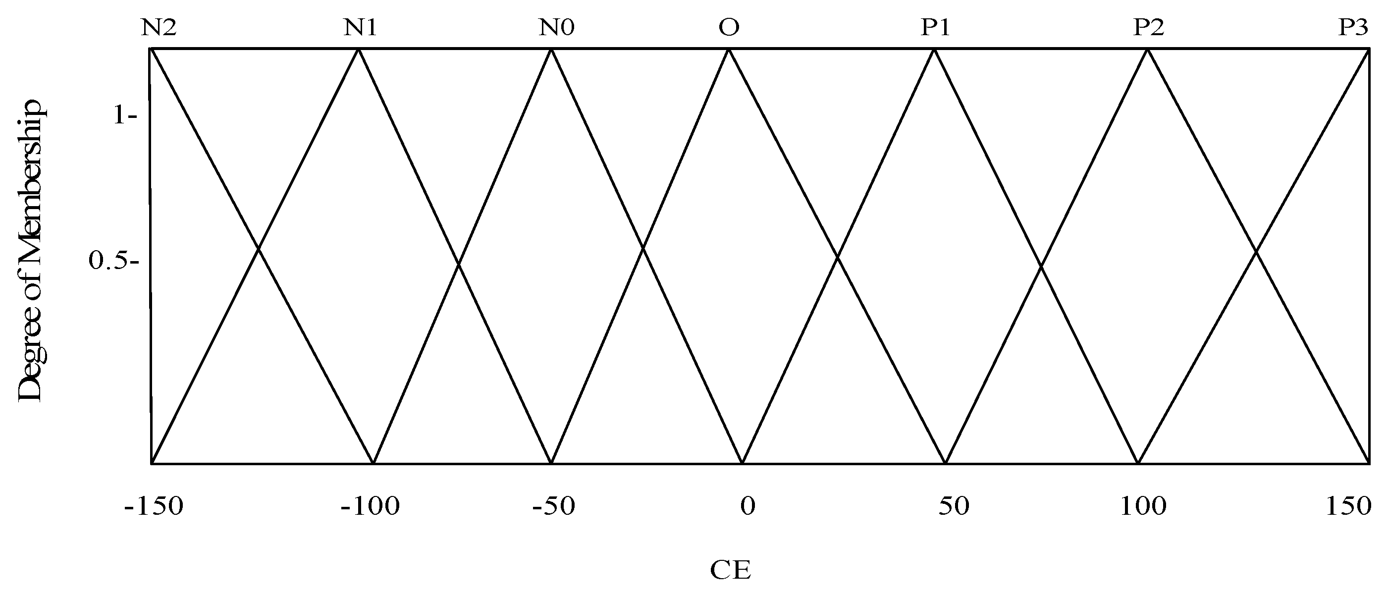
| Change in error | |
| SRFT | Synchronous Reference-frame theory |
| TSR | Tip speed Ratio |
| HCC | Hysteresis current control |
References
- Vijayakumar, G.; Nitin, G.; Gupta, R.A. Mitigation of power quality problems using shunt active power filters: A comprehensive review. In Proceedings of the 12th IEEE Conference on Industrial Electronics and Applications (ICIEA), Siem Reap, Combadia, 18–20 June 2017. [Google Scholar]
- Metin, K.; Engin, O. Synchronous-Reference-Frame-Based Control Method for UPQC under Unbalanced and Distorted Load Conditions. IEEE Trans. Ind. Electron. 2011, 58, 3967–3975. [Google Scholar]
- Suresh, M.; Panda, A.K. PI and Fuzzy Logic Controller based 3-phase 4-wire Shunt active filter for mitigation of Current harmonics with Id-Iq Control Strategy. J. Power Electron. 2011, 11, 914–921. [Google Scholar]
- Soumya, R.D.; Prakash, K.R.; Asit, M.; Gayadhar, P. Power Quality Enhancement in PV and Battery Storage Based Microgrid Using Hybrid Active Filter. In Proceedings of the 3rd International Conference on Energy, Power and Environment: Towards Clean Energy Technologies, Shillong, India, 5–7 March 2021. [Google Scholar]
- Suresh, M.; Panda, A.K. RTDS hardware implementation and simulation of SHAF for mitigation of harmonics using p-q control strategy with PI and Fuzzy logic controllers. Front. Electr. Electron. Eng. 2012, 7, 427–437. [Google Scholar]
- Lin, H.C. Intelligent Neural Network-Based Fast Power System Harmonic Detection. IEEE Trans. Ind. Electron. 2007, 54, 43–52. [Google Scholar] [CrossRef]
- Dash, P.K.; Panda, S.K.; Lee, T.H.; Xu, J.U.; Routray, A. Fuzzy and Neural Controllers for Dynamic Systems: An Overview. In Proceedings of the Second International Conference on Power Electronics and Drive Systems, Singapore, 26–29 May 1997. [Google Scholar]
- Sachin, D.; Bhim, S. Design and Performance Analysis of Three-Phase Solar PV Integrated UPQC. In Proceedings of the IEEE 6th International Conference on Power Systems(ICPS), New Delhi, India, 4–6 March 2016. [Google Scholar]
- Viswanth, K.; Santanu, K.D.; Kumari, R.G. Development and Analysis of Power Quality by using Fuel cell based Shunt Active Power Filter. In Proceedings of the 2020 2nd International Conference on Innovative Mechanisms for Industry Applications (ICIMIA), Banglore, India, 5–7 March 2020. [Google Scholar]
- Alok, K.M.; Soumya, R.D.; Prakash, K.R.; Ranjan, K.M.; Asit, M.; Dillip, K.M. PSO-GWO Optimized Fractional Order PID Based Hybrid Shunt Active Power Filter for Power Quality Improvements. IEEE Access 2022, 8, 74497–74512. [Google Scholar]
- Kumar, C.; Jaisiva, S.; Clement, R.A.; Logeshwari, V. Hybrid renewable energy based smart grid system for reactive power management and voltage profile enhancement using artificial neural network. Energy Sources Part ARecovery Util. Environ. Eff. 2021, 43, 2419–2442. [Google Scholar]
- Mohanraj, M.R.; Prakash, R.A. Unified Power Quality Conditioner for Power Quality Improvement in Distributed Generation Network Using Adaptive Distributed Power Balanced Control (ADPBC). Int. J. Wavelets Multi-Resolut. Inf. Process. 2020, 18, 1941021. [Google Scholar] [CrossRef]
- Krishna, S.; Debashis, C.; Goswami, S.K. A modified PV-wind-PEMFCS-based hybrid UPQC system with combined DVR/STATCOM operation by harmonic compensation. Int. J. Model. Simul. 2020, 41, 243–255. [Google Scholar]
- Ramesh, J.; Suneel, T.; Prakash, R.B.; Vijay Muni, T. Analysis of sliding mode controller based DSTATCOM for power quality improvement in distribution power system. Mater. Today Proc. 2021, in press. [Google Scholar]
- Dheeban, S.S.; Muthu Selvan, N.B. ANFIS-based Power Quality Improvement by Photovoltaic Integrated UPQC at Distribution System. IETE J. Res. 2021. [Google Scholar] [CrossRef]
- Mohamed, A.; Philippe, P.; Shahram, K.; Shahrokh, S. New digital reference current generation for shunt active power filter under distorted voltage conditions. Electr. Power Syst. Res. 2009, 79, 759–765. [Google Scholar]
- Almelian, M.; Mohd, I.; Omran, M.; Sheikh, U. Performance of unified power quality conditioner (UPQC) based on fuzzy controller for attenuating of voltage and current harmonics. IOP Conf. Ser. Mater. Sci. Eng. 2018, 3, 12–84. [Google Scholar] [CrossRef]
- Vinothkumar, V.; Kanimozhi, R. Power flow control and power quality analysis in power distribution system using UPQC based cascaded multi-level inverter with predictive phase dispersion modulation method. J. Ambient. Intell. Humaniz. Comput. 2021, 12, 6445–6463. [Google Scholar] [CrossRef]
- Tejinder, S.S.; Lakhwinder, S.; Gill, B.; Om Parkash, M. Effectiveness of UPQC in Mitigating Harmonics Generated by an Induction Furnace. Electr. Power Compon. Syst. 2018, 46, 629–636. [Google Scholar]
- Samal, S.; Hota, P.K. Design and analysis of solar PV-fuel cell and wind energy based microgrid system for power quality improvement. Cogent Eng. 2017, 4, 1402453. [Google Scholar] [CrossRef]
- Nandhini, E.; Sivaprakasam, A.A. Review of Various Control Strategies Based on Space Vector Pulse Width Modulation for the Voltage Source Inverter. IETE J. Res. 2020, in press. [Google Scholar] [CrossRef]
- Garima, G.; Pankaj, K.G. Self-adaptive learning based controller to mitigate PQ issues in internet of things devices. Int. Trans. Electr. Energy Syst. 2021, 31, e12888. [Google Scholar]
- Nafeh, A.A.; Heikal, A.; El-Sehiemy, R.A.; Salem, W.A. Intelligent fuzzy-based controllers for voltage stability enhancement of AC-DC micro-grid with D-STATCOM. Alex. Eng. J. 2022, 61, 2260–2293. [Google Scholar]
- Sayed, J.A.; Sabha, R.A.; Ranjan, K.J. Biogeography based optimization strategy for UPQC PI tuning on full order adaptive observer based control. IET Gener. Transm. Distrib. 2021, 15, 279–293. [Google Scholar]
- Renduchintala, U.K.; Pang, C.; Tatikonda, K.M.; Yang, L. ANFIS-fuzzy logic based UPQC in interconnected microgrid distribution systems: Modeling, simulation and implementation. J. Eng. 2021, 21, 6–18. [Google Scholar] [CrossRef]
- Devassy, S.; Singh, B. Performance analysis of solar pv array and battery integrated unified power quality conditioner for microgrid systems. IEEE Trans. Ind. Electron. 2021, 68, 4027–4035. [Google Scholar] [CrossRef]
- Rajesh, P.; Shajin, F.H.; Umasankar, L. A Novel Control Scheme for PV/WT/FC/Battery to Power Quality Enhancement in Micro Grid System: A Hybrid Technique. Energy Sources Part A Recovery Util. Environ. Eff. 2021, 1–17. [Google Scholar] [CrossRef]
- Dheeban, S.S.; Muthu Selvan, N.B.; Umashankar, S. Artificial Neural Network based Solar Energy Integrated Unified Power Quality Conditioner. Energy Sources Part A Recovery Util. Environ. Eff. 2021. [Google Scholar] [CrossRef]
- Fredrick, N.; Franklin, N.; Ifedayo, O.; Ramon, Z. Optimal Design and Performance Analysis of Solar PV Integrated UPQC for Distribution Network. Eur. J. Electr. Eng. Comput. Sci. 2021, 5, 39–46. [Google Scholar]
- Gade, S.; Agrawal, R.; Munje, R. Recent Trends in Power Quality Improvement: Review of the Unified Power Quality Conditioner. ECTI Trans. Electr. Eng. Electron. Commun. 2021, 19, 268–288. [Google Scholar] [CrossRef]
- Nikita, G.; Seethalekshmi, K. Artificial neural network and synchrosqueezing wavelet transform based control of power quality events in distributed system integrated with distributed generation sources. Int. Trans. Electr. Energy Syst. 2021, 31, e12824. [Google Scholar]
- Nima, K.; Salwa, E.; Rasoul, B.; Zineb, H.; Rahman, H.; Mustapha, M. Enhancement of power quality issues for a hybrid AC/DC microgrid based on optimization methods. IET Renew. Power Gener. 2022, 16, 1773–1791. [Google Scholar]
- Pazhanimuthu, C.; Ramesh, S. Grid integration of renewable energy sources (RES) for power quality improvement using adaptive fuzzy logic controller based series hybrid active power filter (SHAPF). J. Intell. Fuzzy Syst. 2018, 35, 749–766. [Google Scholar] [CrossRef]


| Component | Rating |
|---|---|
| Source | : 0.150 mH |
| Shunt compensator | : 1.0 µf hysteresis band: 0.010 A |
| DC-Link | Voltage: 700.0 V |
| Equipment | Parameter | Rating |
|---|---|---|
| Li-ion battery | Rated-capacity | 400 Ah |
| Maximum-capacity | 500 Ah | |
| Nominal-voltage | 750 V | |
| Maximum-voltage | 756 V | |
| Wind Turbine | Nominal turbine mechanical power | 3 MW |
| Base wind speed | 11 m/s | |
| Pitch angle controller integral gain | 5 | |
| Pitch angle controller proportional gain | 25 | |
| Maximum pitch angle | 45 deg. | |
| Maximum rate of change of pitch angle | 25 deg./s |
| Level of WPG | Action |
|---|---|
| . | |
| No WPG | . |
| Er | CE | ||||||
|---|---|---|---|---|---|---|---|
| P2 | P1 | P0 | O | N0 | N1 | N2 | |
| N2 | O | N0 | N1 | N2 | N2 | N2 | N2 |
| N1 | P0 | O | N0 | N1 | N2 | N2 | N2 |
| N0 | P1 | P0 | O | N0 | N1 | N2 | N2 |
| O | P2 | P1 | P0 | O | N0 | N1 | N2 |
| P0 | P2 | P2 | P1 | P0 | O | N0 | N1 |
| P1 | P2 | P2 | P2 | P1 | P0 | O | N0 |
| P2 | P2 | P2 | P2 | P2 | P1 | P0 | O |
| Load | Case 1 | Case 2 | Case 3 | Case 4 | Case 5 |
|---|---|---|---|---|---|
| Balanced supply voltage | ✓ | ✓ | ✓ | ✓ | |
| Unbalanced supply voltage | ✓ | ||||
| 11 m/s wind speed | ✓ | ✓ | ✓ | ||
| 10 m/s wind speed | ✓ | ✓ | |||
| Balanced Rectifier Load: 30.00 Ω & 20.00 mH | ✓ | ✓ | ✓ | ||
| Unbalanced R-L Load: R: 10, 20 &15 Ω; L: 9.50, 10.50 & 18.50 mH. | ✓ | ✓ | ✓ | ||
| Induction Furnace load: LC = 400.0 mH, 50.0 μF RL = 10.0 Ω, 100.0 mH | ✓ |
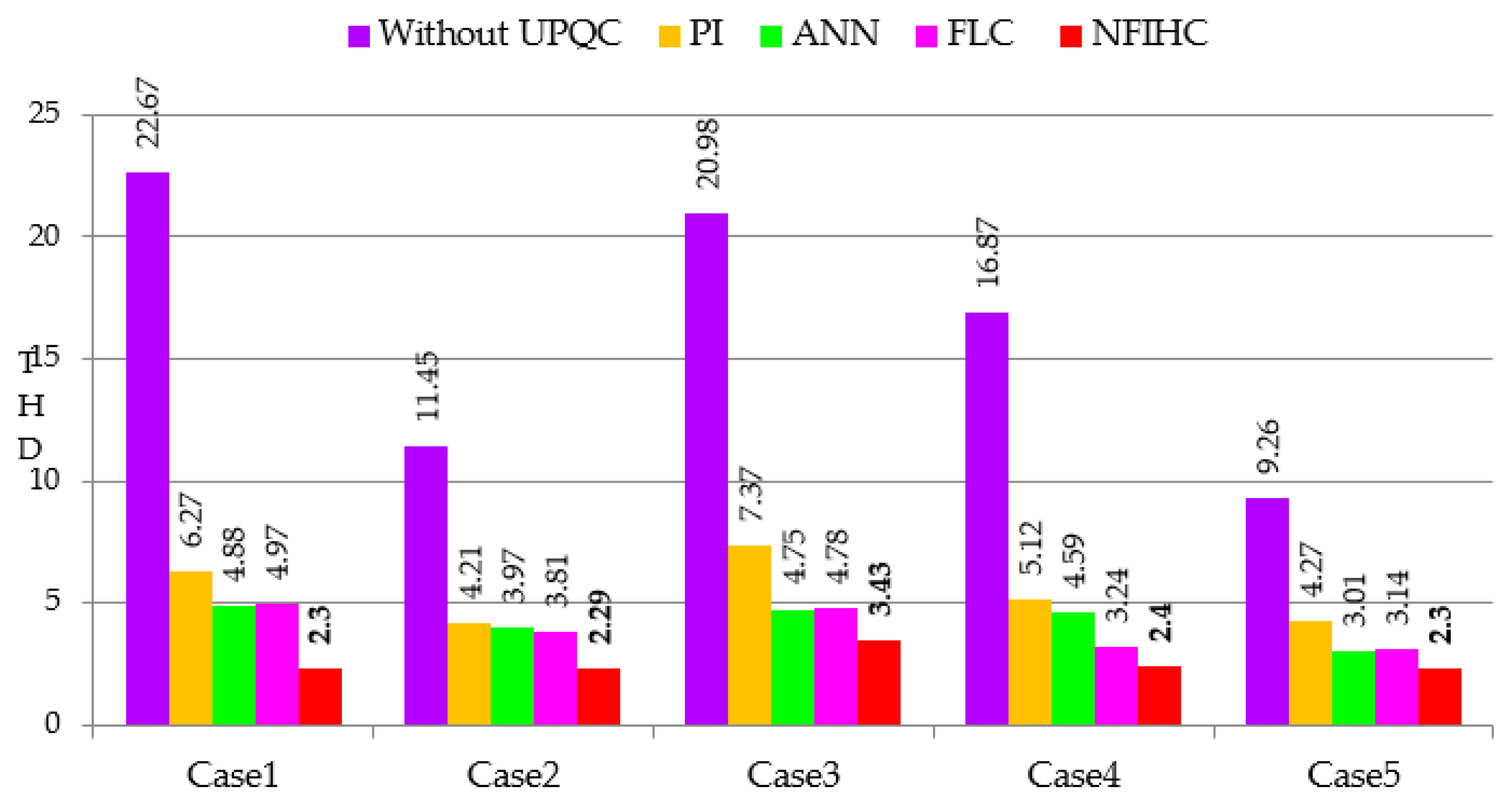
| Method | Case 1 | Case 2 | Case 3 | Case 4 | Case 5 |
|---|---|---|---|---|---|
| Without SH-SPVBS | 22.67 | 11.45 | 20.98 | 16.87 | 9.26 |
| PI | 6.27 | 4.21 | 4.37 | 5.12 | 4.27 |
| ANN | 4.88 | 3.97 | 4.75 | 4.59 | 3.01 |
| FL | 4.97 | 3.81 | 4.78 | 3.24 | 3.14 |
| PI-C [20] | 3.28 | -- | -- | -- | -- |
| SMC [20] | 2.44 | -- | -- | -- | -- |
| PI [25] | 14.74 | -- | -- | -- | -- |
| FL [25] | 6.13 | -- | -- | -- | -- |
| ANFIS [25] | 2.43 | -- | -- | -- | -- |
| PIC [33] | 3.65 | -- | -- | -- | -- |
| FLC [33] | 2.52 | -- | -- | -- | -- |
| NFIHC | 2.30 | 2.29 | 3.43 | 2.4 | 2.30 |
Publisher’s Note: MDPI stays neutral with regard to jurisdictional claims in published maps and institutional affiliations. |
© 2022 by the authors. Licensee MDPI, Basel, Switzerland. This article is an open access article distributed under the terms and conditions of the Creative Commons Attribution (CC BY) license (https://creativecommons.org/licenses/by/4.0/).
Share and Cite
Koganti, S.; Koganti, K.J.; Salkuti, S.R. Design of Multi-Objective-Based Artificial Intelligence Controller for Wind/Battery-Connected Shunt Active Power Filter. Algorithms 2022, 15, 256. https://doi.org/10.3390/a15080256
Koganti S, Koganti KJ, Salkuti SR. Design of Multi-Objective-Based Artificial Intelligence Controller for Wind/Battery-Connected Shunt Active Power Filter. Algorithms. 2022; 15(8):256. https://doi.org/10.3390/a15080256
Chicago/Turabian StyleKoganti, Srilakshmi, Krishna Jyothi Koganti, and Surender Reddy Salkuti. 2022. "Design of Multi-Objective-Based Artificial Intelligence Controller for Wind/Battery-Connected Shunt Active Power Filter" Algorithms 15, no. 8: 256. https://doi.org/10.3390/a15080256
APA StyleKoganti, S., Koganti, K. J., & Salkuti, S. R. (2022). Design of Multi-Objective-Based Artificial Intelligence Controller for Wind/Battery-Connected Shunt Active Power Filter. Algorithms, 15(8), 256. https://doi.org/10.3390/a15080256