Article

Novel Algorithm for Multi-Time Data Implantation in a Special Cyber-Manufacturing Architecture

by
Mahbubun Nahar
1,†,
A. H. M. Kamal
1,*,†,
Md Rafiul Hassan
2 and
Mohammad Ali Moni
3,*
1
Department of Computer Science and Engineering, Jatiya Kabi Kazi Nazrul Islam University, Mymensingh 2224 , Bangladesh
2
Department of Computer Science and Engineering, University of Maine at Presque Isle, 181 Main Street, Presque Isle, ME 04769, USA
3
Artificial Intelligence & Digital Health Data Science, School of Health and Rehabilitation Sciences, Faculty of Health and Behavioural Sciences, The University of Queensland, St Lucia, QLD 4072, Australia
*
Authors to whom correspondence should be addressed.
These authors contributed equally to this work.
Algorithms 2022, 15(10), 335; https://doi.org/10.3390/a15100335
Submission received: 31 July 2022 / Revised: 19 August 2022 / Accepted: 9 September 2022 / Published: 20 September 2022
(This article belongs to the Section Algorithms for Multidisciplinary Applications)

Abstract

:
A physical cyber system connects all authenticated cyber devices in its network. Nowadays, many wearable devices function as cyber devices. In essence, people are using these devices more for their healthcare. These devices would be very popular if an easy-to-use manufacturing architecture could be created and, at the same time, the devices could protect the data stored on the device. In this article, we suggest a good manufacturing architecture for a healthcare device, in which our proposed data protection method works well. The architecture is very simple to implement and the data protection method hides information in a DNA sequence. The present DNA-based data hiding schemes implant secrets in converted binaries of nucleotides. The number of implanted bits is no more than the length of nucleotides, however, these schemes expand the stego DNA sequence noticeably. While implanting a large message, e.g., historical records of patients, it would be harder for these schemes to manage the implantation of the whole secret in a single DNA sequence. A large DNA sequence might be a solution in some contexts. Nevertheless, managing a large DNA sequence and its expanded part in a fixed memory space would be challenging as those are too large in size. To address this problem, we propose a multi-time data embedment method that could implant as much data in a DNA sequence as needed. Although it presents a greater embedding capacity, it does not increase the length of the modified DNA/RNA sequence. Thus, it optimizes the extra memory load in the chip. The proposed method implemented several features to improve the security of both implanted data and DNA sequence. The experimental results outperform all measurements over the competing schemes.

1. Introduction

Cyber manufacturing is one of the most influential branches of the physical cyber system. Typically, a cyber-manufacturing system focuses on the architecture of the devices used in cyber systems, their data acquisition, retrieval and processing methods, the functional efficiency and security features of data and devices [1]. At the same time, it deals with related engineering and technological aspects of the devices to make them good-looking, easy to use and strong. Very commonly used cyber devices are smart watches, healthcare and assistance devices of disabled and elderly people [2]. With the advancement in industry and technology, those devices have started to stand out in terms of their functionality. In today’s world, no one doubts that, in near future, a small device will provide us with multiple services, e.g., we could add our own security, day-to-day work, accounting, asset management, etc. Then, body-worn devices will obtain a different dimension. These devices will be widely used to simplify our day-to-day operations and increase security [2].
Certainly, these devices will include healthcare services, as well. Current healthcare devices are capable of storing several pieces of casual information about the people who wear them. Some devices may update a user’s information to a limited extend through a set of device-implanted sensors. However, future healthcare devices will show many surprises that are unimaginable compared to the present time. They will be able to perform many physical and pathological experiments on the human body automatically. These devices will automatically start communicating with the designated doctors or any healthcare provider to receive suggestions and consultations. It will not be surprising if a robotic device takes its owner to the doctor or hospital if it senses the deteriorated health condition of the owner. Although we have started to see similar applications in a short range, there are still questions about their capability and the quality of their skills. That limitation is mainly due to the small size and low-cost demand of such devices. However, we expect better services from them by making them capable of processing and storing huge amounts of information.
The healthcare devices will store demographic, pathological, historical and other data of the owner in their memory. This information will be updated regularly. In that case, if we preserve the historical data, at some point in time, that data will become larger, especially for old patients and chronic diseases. It could even be larger than the memory capacity of the device. Again, the information stored on the device will be threatened because the device will be connected to the cyber world and its information can easily be stolen if we store plane data in them. Hence, processing data to a secured format is essential. Moreover, failure to provide data protection will also hamper the cyber-manufacturing process. Therefore, in these days, the security breach on the information will be a big obstacle in the way of obtaining good service. If we do not work now on the security architecture of the cyber-manufacturing world, the cyber-manufacturing method, especially on wearable healthcare devices, will not be implemented [3]. Consequently, we have to look at three things—(i) a simple architecture for the device, (ii) its information management and (iii) information security. Hence, in this article, we place an emphasis on developing an architecture for future healthcare devices and an efficient algorithm for their data management and security.
Our primary target is to design a simple but effective architecture. We first assume that the intended wearable cyber device is equipped with the necessary sensors to collect and process human health information as well as to store them. The sensors are connected to a memory unit and a signalling unit through the processing unit of the device. The memory unit consists of two parts—a restricted part and a reusable part. The initial information of the person, e.g., the demographic information of a person, will be kept in a restricted part of the memory at the time of manufacturing or in the one-time erasable memory of the device. Generally, this are very ordinary personal information, e.g., name, parent’s name, address, gender, etc. All of this information will be encrypted and stored in that stated memory. The details of the architecture are given at Section 3.
Our secondary target is to meet the demand of storing a large volume of data, even if it is an ever-growing dataset. As we are working on smart devices where memory size is a concerning issue, we have presented a method of repeatedly implanting secrets in a small-sized cover. As a medium, we have chosen a small DNA/RNA sequence. That technique has helped us in both managing large data and securing them.
The proposed scheme has several distinct features: (i) It presents a simple architecture for cyber devices that will be a boon for production in the industry; (ii) The architecture would be useful for managing its memory, a signaling unit and sensors effectively and building a perfect synchronization among these units; (iii) Uses of restricted memory will allow the devices to be used for other purposes, e.g., in banking, owner identifying, etc.; (iv) As far as we know, no other study has used a small chunk of nucleotides for embedment of a large volume of data, e.g., a chunk of the ten nucleotides is enough to conceive any volume of information; (v) A multi-time implantation method is proposed for the first time in the field of its kind; (vi) There is no other scheme that generalizes its functionality to work with any size of message, e.g., message size of some multiple of the length of DNA; (vii) Shuffling elements in the stego key by the proposed scheme is an innovative idea that is effective for improving the security of data. For this, we think that the proposed method will be a striking one in the field of cyber physical manufacturing, as well as the DNA-based data hiding arena.
The study involved experiments on real medical data, as well as on four separate RNA and three DNA sequences to justify its robustness. Four RNA sequences of COVID-19 and one DNA sequence were taken from the NCBI repository. The RNA sequences of nCoV-19 and DNA sequences are open to all [4,5,6,7] and, therefore, freely available. Two additional sequences were prepared by us from real data. The proposed method worked successfully in all the RNA/DNA sequences and provided promising results.
The article comprises seven sections. Section 2 is provided to give a description of the background studies. Section 3 narrates the proposed cyber physical manufacturing architecture. The proposed multi-time data embedment method is given in Section 4. Section 5 analyses the proposed scheme. We discuss the results in Section 6. Section 7 concludes the article.

2. Background Study

2.1. Related Study on Architecture

Kamal and Islam in [8,9] presented two architectures for securing data in a smart card. They implanted patients’ data in the card owner’s photograph. However, these methods can neither handle the sensor data nor connect the devices to a cloud and doctors. Rather, the information security provisions have been worked out in those schemes, when someone wants to receive healthcare at a terminal using a smart card. Lin W. D. and Low Y. H. in 2020 [10] proposed a digital twin architecture of the physical cyber system. Again, Liu, Xiaoqing F. et al. [11] in 2017 proposed a communication layer architecture of the cyber physical system. However, they did not state the hardware architecture of the device, which is essential for manufacturing industries.

2.2. Related Study on Data Security

Cryptography is a traditional method of managing the secrecy of the message. In cryptography, an encryption technique destroys the meaning of the data. The sender side does it at its end using a suitable key. The secret key helps the communicating parties to decrypt the modified data at the retriever end [12]. A smart technique of present data communication is to hide the secret message in a media, e.g., image, audio, video. The processes of hiding data in media are classified as watermarking and steganography. Watermarking is mainly used to provide data integrity, rather than security [13,14,15]. On the contrary, steganography is the art of hiding message data in a cover medium for securing a data communication method. A steganography method modifies the cover medium by some rules while implanting the secret message in it. The modified medium then called stego media. The steganography process makes the data invisible in the stego medium and thus, one cannot realize the existence of a secret in it while the stego medium is stolen. In fact, the system attains the ability of deceiving unauthorized person or devices pretending that there is nothing more inside the media. Therefore, the interest from both the data handler and the number of researchers is increasing in the field of steganography. Steganography schemes are broadly classified into two groups—reversible and irreversible. Reversible schemes retrieve both data and cover media at the extractor end without taking any help from the encoder module [9,16,17,18,19,20,21,22,23,24]. On the other hand, irreversible schemes only extract secret data from the stego contents [8,25,26,27,28,29]. These schemes are not concerned with rebuilding the cover media.
Although image, audio and video are famous media for steganography, recently, some researchers have used a deoxyribonucleic acid (DNA) sequence in the cloud as a medium of hiding secrets [30,31]. DNA sequences are available at various repositories. A very renowned one is NCBI [7,30,31]. Rahman et al. [30] and Hamed G. et al. [31] implanted secret bits in DNA. In 2019, the authors in [30] stated a DNA data hiding approach for data authenticity in mobile cloud. The cloud was based on the healthcare system. The authors used a cover DNA sequence with nucleotides A, C, G, T of length l. They implanted a message M of n-bits. They converted the DNA sequence into a 2D matrix with n rows and l / n columns. They randomly calculated a one-time string E of n-bits. That E was a secret key. The method divides both M and E in σ segments with b-bits each, where σ = n / b and 2 b l / n . They also used a substitution rule (SR), presented in Table 1, where they used ‘00’ for nucleotide ‘A’, ‘01’ for ‘C’, ‘10’ for ‘G’ and ‘11’ for ‘T’.
The position of a nucleotide in a 2D matrix was selected randomly using a sequence generator. The column sequence was stored in a set of named payload (R). Then, the method substitutes a pointed nucleotides by mapping binary values of the SR table, i.e., Table 1. That substitution mechanism produced a codeword W s of length of b-bits. After that, W ¯ s were generated by the exclusive OR operation between message segment M s , codeword W s , and string segment E s . The W ¯ s was converted into nucleotides according to the SR. A 2D matrix was generated after repeating the aforementioned process and this 2D matrix was transformed into one-dimensional vector of nucleotides. Finally, it appended the payload R and tail T with the one-dimensional vector to construct the stego DNA sequence C ¯ . The stego DNA sequence C ¯ and a stego key SK are sent to the cloud, where the stego key contains l , M , E , b , SR and a seed for generating a pseudo-random sequence. The length of C was less than the length of C ¯ .
Hamed G. et al. in 2016 [31] combined cryptography and steganography to hide data in the DNA sequence as well as to improve the volatility of stego DNA. The method first converts the DNA and the cipher text into binary. The scheme places bits of cipher text into arbitrary position of DNA’s binary using true random number seed. That placement introduces an expansion in the final string. The scheme executes a conversion method to create stego nucleotides from these binaries. Instead of managing true random number seed, the scheme was simple by nature.
Wang et al. [32] in 2019 applied a recombinant DNA technique to embed secrets in DNA sequence. The method works in two phases. First, it converts each character of message in to a DNA triplet, known as encoded message. The scheme next selects a cover DNA and a reference DNA. During data embedment, a three-input-based substitution table maps to a single nucleotide where these three input elements come from cover DNA sequence, reference DNA sequence and encoded message, respectively and progressively. The mapped values are called setgo DNA sequence. As the method is based on living organisms, at its second phase, it ligases the stego DNA sequence with a selectable marker and thus, it obtains a recombinant DNA sequence. Finally, the method transforms that recombinant DNA sequence into a host cell. These cells, along with many dummy cells, are sent to a destination. After cultivating these cells, reversible functions are applied to extract the secrets and the cover DNA sequence. As the second phase is fully based on biological affairs and it does not conceive any secret message there, we correlate only its first phase with our scheme.

3. Proposed Architecture

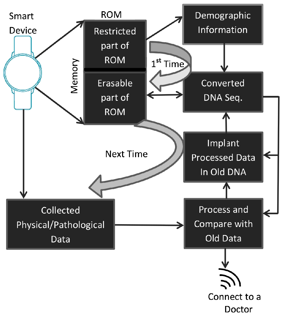
The list of main hardware of the target smart devices is a processing unit, a memory unit, a set of sensors for collecting user data, a wireless sensor to connect to the cloud and a set of connections among the units. The memory unit consists of a restricted ROM and a general purpose ROM. These two ROMs could be implanted in the device as either two separate ROMs or in a single ROM. In the second case, a part of the ROM will be declared as a restricted part of the memory. The restricted ROM is writable for a single time only. The demographic information of the device owner will be written there.
The proposed method will convert this demographic information into a DNA sequence. The converted DNA sequence will be stored in an erasable ROM (E-ROM) (or part of one). In all subsequent tasks, it will achieve five aims—(i) it will gather the latest health information of a person through its sensors; (ii) it will collect the previously stored information from E-ROM and will extract all healthcare data; (iii) it will understand the situation of the patient by comparing that information with the most recently collected information; (iv) if that measurement signifies some serious issues that are to be treated soon, it will take the necessary steps to save the patient, otherwise, it will notify the person through a gentle signalling process; (v) it will update the device memory with the latest information. The updating task will be performed by the proposed data hiding technique. The architecture of the proposed cyber-manufacturing system is graphically shown in Figure 1. The functionality of the hardware equipment of the proposed architecture is described in detail in the section on the analysis of the proposed method with a different figure.
A concern issue of this research work is to secure the information in the second and fifth steps of the above five tasks. For this, during its update task, the scheme will implant the latest information in the previously stored DNA sequence. That is why it is advised to generate a DNA sequence from the owner’s demographic information at the first stage of the device registration.
The proposed scheme will convert the demographic information to a DNA sequence, as explained. That conversion technique will, indeed, make the information useless to outer applications. However, this demographic information might be used for other purposes, e.g., in banking. To make the device usable for applications other than healthcare, we have preserved this demographic information in a restricted ROM as raw data.

4. Proposed Method of Securing Data in Cyber Device

It is already mentioned that a major issue of concern in this research is to secure the data at the fifth operational step, as stated in the proposed architecture. We intend to apply a data embedment policy for establishing a data security task. The embedment is performed in the fake DNA sequence where the fake DNA sequence was generated from demographic information of the device owner. However, the length of the fake DNA sequence would not be long enough to conceive the information in a single DNA sequence, because the information might be larger than the length of the DNA sequence for considering historical data. For example, if we consider a cyber device for a patient that will mainly be used for telemedicine purposes or as a smart medical card, the device has to save all previous information of the patient as well as the current information. Such data become larger for a chronically ill or old patient. To overcome this problem, we, in this research, apply multi-time data embedment in the same DNA sequence.

4.1. Proposed Multi-Time Data Embedment Scheme

All DNA sequences comprise A, C, G and T named nucleotides. According to [4,5,6,33,34], the RNA sequence of nCoV-19 also consists of the same four nucleotides. Let a RNA sequence of nCoV-19 is N r . As an example, consider, N r = “AGGCTCCA…”. The proposed method implants a binary message stream M in the nucleotides of N r .

4.1.1. Secret Implantation Method

Figure 2 depicts the whole embedding process. The algorithmic steps of the proposed multi time data implantation method are presented in Algorithm 1 and shown in Figure 2 as well.
Algorithm 1: Data Implantation
1. 
Nucleotides in N r are converted to binary values according to Table 1. Let the converted binaries of the RNA sequence be R. The size of R is twice that of N r as two bits of binary are generated for each of the nucleotides.
2. 
Measure the length of R and store that integer value in L.
3. 
Generate a secret key S that consists of L number of binary bits.
4. 
Divide the binary message M into M 1 , M 2 , , M n , M t , where the size of each of M 1 to M n is L and the size of the last chunk M t could be equal to or less than L and M = M 1 M 2 M n M t , when   stands for concatenation of binary string. Let the length of M t be L t . Thus, the total length of the message is n × L + L t bits. Now, append L L t number of zeros to the left of M t to make it of equal size to M 1 .
5. 
Set R ˜ = R and R ˜ x = R .
6. 
The following loop executes two statements for n + 1 times. Each time, it takes a chunk of message M i from M. It generates stego results by performing an exclusive-OR operation of M i with R ˜ and S. At the first stage of the loop, R ˜ means R, according to step 5. After each execution of Equation (1), R ˜ is appended to the end of R ˜ x according to Equation (2). R ˜ x is a dynamically expandable array where each time it is enlarged by L. The objective of uses of R ˜ x is to keep track of stegos of first ( n 1 ) cycles. That is why the length of R ˜ x is ( n 1 ) × L . The proposed scheme will make it a part of stego key. Stegos of the last cycle are stored at R ˜ . The length of R ˜ is L. Finally, these R ˜ and R ˜ x are converted to N ˜ r and N ˜ x , respectively. For i = 1 to n + 1, do
R ˜ = R ˜ S M i ,
where ⊕ stands for exclusive-OR operator.
If i < ( n + 1 )
R ˜ x = R ˜ x R ˜
End if
End loop
7. 
Grouping bits into pairs and converting R ˜ and R ˜ x into nucleotides again according to Table 1, we obtain the stego nucleotides. Let the sequences of stego nucleotides be N ˜ r and N ˜ x , respectively. The sender side, thus, implants n × L bits of secrets in an RNA sequence and produces two new stego sequences N ˜ r and N ˜ x . Among these two, N ˜ r is used as stego nucleotides and stored to a cloud for further uses. The other sequence, i.e., N ˜ x , is kept as a part of the stego key. The length of N ˜ r is the same as that of N r and the length of N ˜ x is n 1 times that of N r .
The scheme could also serve in both standalone and cloud based applications. In cloud-based application, only the N ˜ r will be stored in a cloud space. The intended person will collect N ˜ r from the cloud and then will request the sender side/server for a stego key. In that case, only a cloud space of L / 2 nucleotides is enough for communicating n × L bits of the message.

4.1.2. Stego Key Generation

The stego key is a secret key that is used to extract the implanted secrets from the stego DNA/RNA. The encoder was privately communicated to share it. Thus, the authorized decoder collects it from the encoder. The stego key consists of N ˜ x , length of message bits L that are implanted at the last cycle, total execution cycle n and the secret key S. Thus the stego key (SK), as shown in Table 2, was defined by S K = < N ˜ x , L , n , S > . The length of S K is shown in Table 2.

4.1.3. Data Extraction Method

The destination end, i.e., decoder, might collect N ˜ r from either cloud, standalone system or through a communication link according to nature of the application. However, our concern issue was to extract message bits from N ˜ r and to generate cover DNA/RNA N r . Before proceeding to do that, the decoder next collect the SK and thereafter, it separates N ˜ x , L , n and S from S K . The method converts both the N ˜ r and N ˜ x into binary values using Table 1, which are, indeed, R ˜ and R ˜ x , respectively. Concatenate R ˜ and R ˜ x to form R ˜ x , i , where 1 i n + 1 . Next, it divides the R ˜ x into pieces of L bits. Let the pieces are R ˜ x , 1 , R ˜ x , 2 , …, R ˜ x , n + 1 .
The method executes the following steps of Algorithm 2 and Equations (3)–(6) to extract secrets.
Algorithm 2: Data Extraction
Step 1: For i = n + 1 to 2 do step-1
R 1 = R ˜ x , i
R 2 = R ˜ x , i 1
M 1 = R 1 R 2 S
M = M 1 M , w h e r e M i s i n i t i a l l y e m p t y .
End loop
The flowchart of the extraction process is depicted in Figure 3. If we look back at Equation (1), we see that R 1 was produced by performing an exclusive-OR operation among R 2 , S and M i . Therefore, R 1 XOR R 2 XOR S of Equation (5) will produce M i . Equation (6) appends every extracted message chunk to the lagging of M as it extracts each most recently implanted chunk, i.e., it extracts the last chunk first, then the second-last chunk, and so on.
After completing the execution of the loop, R 2 will hold the value of R ˜ x , 1 . That R ˜ x , 1 is mainly R, as presented in step (5) of Figure 1. Hence, R 2 is R. The R is converted to nucleotides N r according to Table 1. As the scheme has the capability to generate N r , it is a reversible method. The proposed reversible method, thus, extracts M and N r at the receiver end.

5. Analysis of Proposed Method

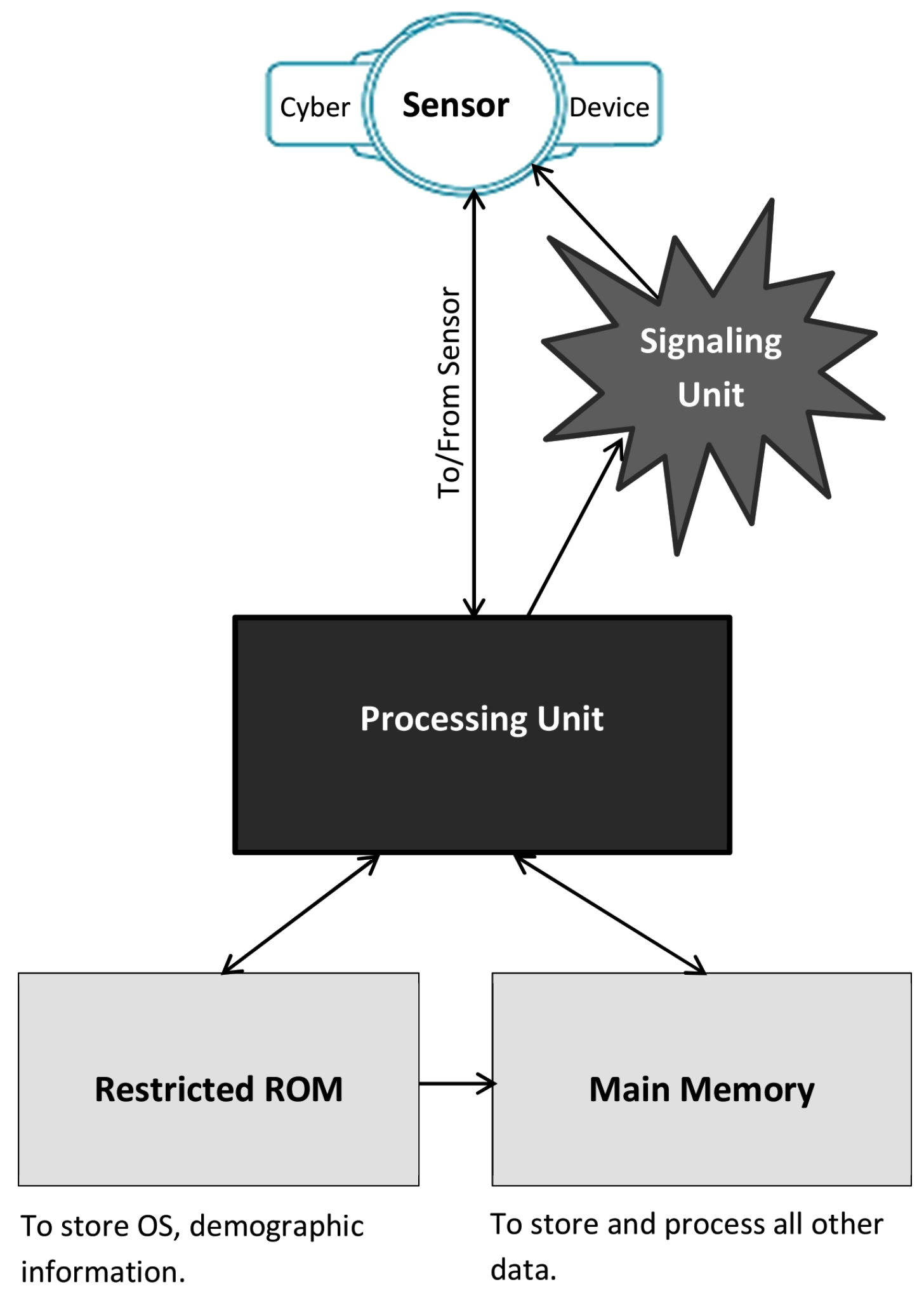
5.1. Manufacturing Architecture

The hardware architecture of the system is depicted in Figure 4.

5.1.1. Manufacturing Architecture: Processing Unit

The processing unit of the cyber device stores demographic information of the device owner in the restricted a memory as raw data. At the same time, it converts the demographic information into a DNA sequence and hides the other information in it using our proposed data hiding method. After that, it saves the stego DNA sequence in the main memory. Next, when the processing unit senses a new piece of data from its sensors, the unit collects the most recently saved DNA sequence from the main memory. The processing unit then extracts the secret data from that stego DNA sequence. The unit also generates the original DNA sequence by the proposed reversible data extraction method. The processing unit compares the newly sensed data with the extracted data. It sends the results to the signaling unit.

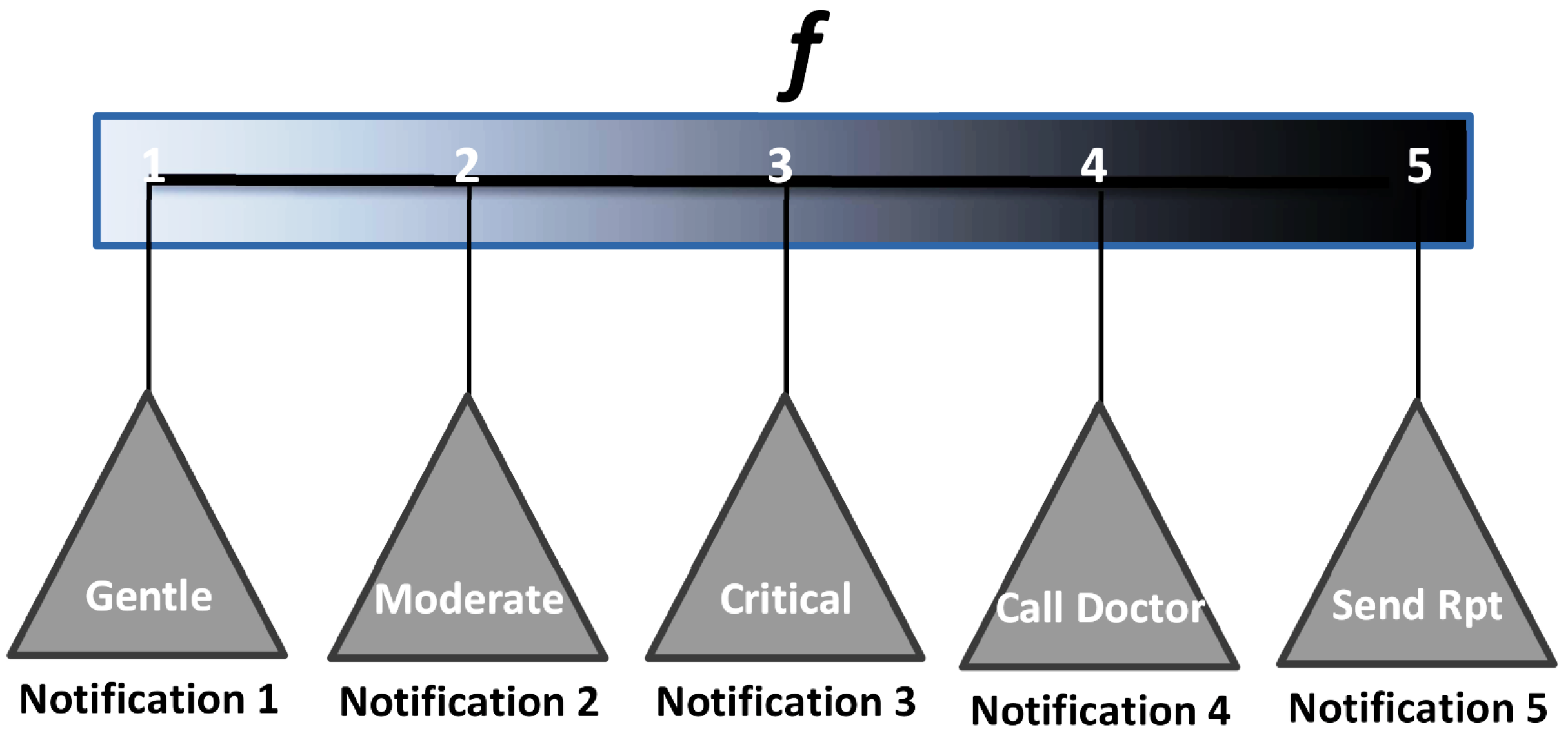
5.1.2. Manufacturing Architecture: Signaling Unit

The signaling unit is developed to provide one of five notifications. The first four notifications are called in-control signals. The last one is referred to as an out-control signal. According to the demand of the users, the manufacturer can increase the number of in- and out-control signals. The signaling unit applies a mathematical function f to generate a number from 1, 2, 3, 4, i.e., f = 1 or f = 2 or f = 3 or f = 4. Here, we have not given any fixed equation as a part of that function. Rather, it is left to the manufacturer so that they can set their own function and fitted parameters according to this proposal or their modified one. The signaling unit may generate one of the four notifications automatically based on a function’s generated value f. When the signaling unit generates f = 1, the cyber device creates a gentle notification. That means that there is no problem in the sensed data. f = 2 indicates some minor changes in the health statistics. The device signals accordingly. Again, f = 3 indicates major changes in the health conditions. The person demands extra care. If the signaling unit measures f = 4, the person is in danger. They should consult a doctor immediately. The signaling unit then automatically calls a designated doctor. Notification 5 is not generated by the auto system of the signaling unit. This is done after receiving a request from a doctor. That request automatically triggers the signaling unit to set f = 5. When the device realizes a value of f = 5 , it sends the report of the last-sensed and the extracted historical data to the doctor. A list of those notifications is shown in Figure 5.

5.2. Analysis on Data Hiding Algorithm

To analyze, the data hiding method first considers a small DNA sequence. Let us consider the sequence TTTGTTGAGT.
Hence, DNA N r : TTTGTTGAGT;
DNA to Binary, R: 11111110111110001011;
Secret Key, S: 00001111110111000001;
Message, M: 101101111000111001100010011101110111010111111110001011100001.
Divide M into chunks of length of L (here, it is 20)
Then, M = 10110111100011100110-00100111011101110101-11111110001011100001
The embedding program returns the following results:
Stego DNA, i.e., N ˜ r : GCTTTTATGA;
Concatenated Stego DNA, i.e., N ˜ x : CACGGGGGTACGTGAAACGAGCTTTTATGA.
In the following, the processing steps and their results are demonstrated.

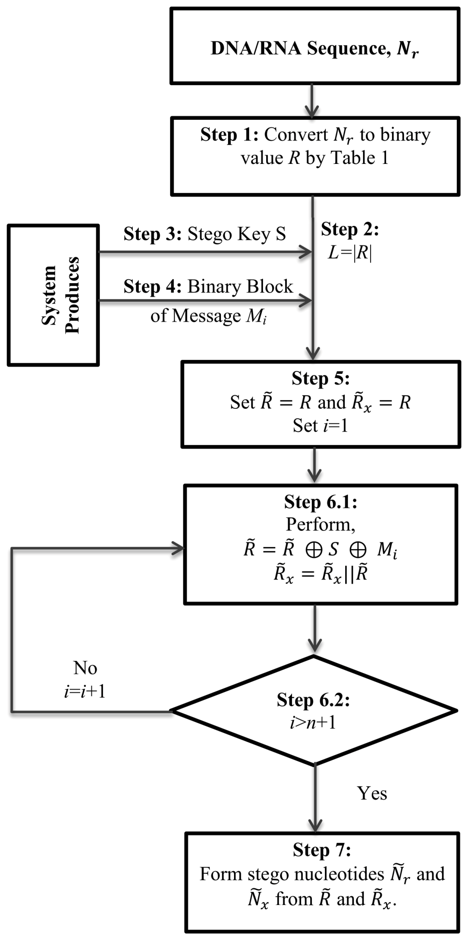
5.3. Execution of Data Implantation Module

In the following, we explain the execution steps of the data implantation module.
  • Execution cycle 1: R ˜ x = R ˜ = R = 11-11-11-10-11-11-10-00-10-11
    Using Equation (2), R ˜ x = R ˜ x R ˜ = 11-11-11-10-11-11-10-00-10-11 ‖ 01-00-01-10-01-10-10-10-11-00
    The result is depicted in Table 3.
  • Execution cycle 2: R ˜ x = 11-11-11-10-11-11-10-00-10-11 ‖ 01-00-01-10-01-10-10-10-11-00 ‖ 01-10-11-10-00-00-00-01-10-00
    The result is shown in Table 4.
  • Execution cycle 3: R ˜ x = 11-11-11-10-11-11-10-00-10-11 ‖ 01-00-01-10-01-10-10-10-11-00 ‖ 01-10-11-10-00-00-00-01-10-00 ‖ 10-01-11-11-11-11-00-11-10-00
    N ˜ r = GCTTTTATGA
    N ˜ x = TTTGTTGAGT-CACGCGGGTA-CGTGAAACGA-GCTTTTATGA
    The result is tabulated in Table 5.

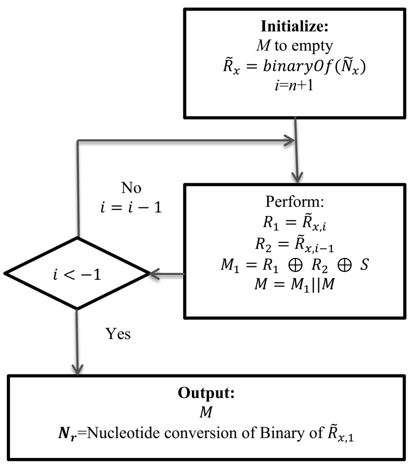
5.4. Execution of Data Extraction Module

Data extraction rules work at receiver end. The receiver end has all the necessary information to extract the implanted data and to reconstruct the cover DNA/RNA. It has
N ˜ x = TTTGTTGAGT-CACGCGGGTA-CGTGAAACGA-GCTTTTATGA;
Secret key, S = 00001111110111000001.
Then, the receiver generates R ˜ x , where R ˜ x = 11-11-11-10-11-11-10-00-10-11 ‖ 01-00-01-10-01-10-10-10-11-00 ‖ 01-10-11-10-00-00-00-01-10-00 ‖ 10-01-11-11-11-11-00-11-10-00
The execution steps are shown below:
  • Execution cycle 1: Using Equation (3): R 1 = 10-01-11-11-11-11-00-11-10-00 (last chunk of R ˜ x ). Using Equation (4): R 2 01-10-11-10-00-00-00-01-10-00 (second chunk of R ˜ x from the last). Using Equation (5), we can compute new R 1 , R 2 , S and M 1 . Here, M 1 is the value of M 3 in the data implantation module. The result is shown in Table 6.
    Using Equation (6), M is computed.
    M = M 1 = 11-11-11-10-00-10-11-10-00-01
  • Execution cycle 2: Now, again, using Equations (3)–(5), we compute R 1 , R 2 and M 1 . In this cycle, the value of M 1 is the same as the value of M 2 in the data implantation module. The result is depicted in Table 7
    R 1 = 01-10-11-10-00-00-00-01-10-00
    R 2 = 01-00-01-10-01-10-10-10-11-00
    Equation (6) gives:
    M = M 1 M = 00-10-01-11-01-11-01-11-01-01 ‖ 11-11-11-10-00-10-11-10-00-01
  • Execution cycle 3: Using Equations (3)–(5), we can compute R 1 , R 2 and M 1 . This M 1 is the same as the M 1 of the data implantation module. The result is depicted in Table 8
    R 1 = 01-00-01-10-01-10-10-10-11-00
    R 2 = 11-11-11-10-11-11-10-00-10-11 Equation (6) yields:
    M = M 1 M = 10-11-01-11-10-00-11-10-01-10 ‖ 00-10-01-11-01-11-01-11-01-01 ‖ 11-11-11-10-00-10-11-10-00-01
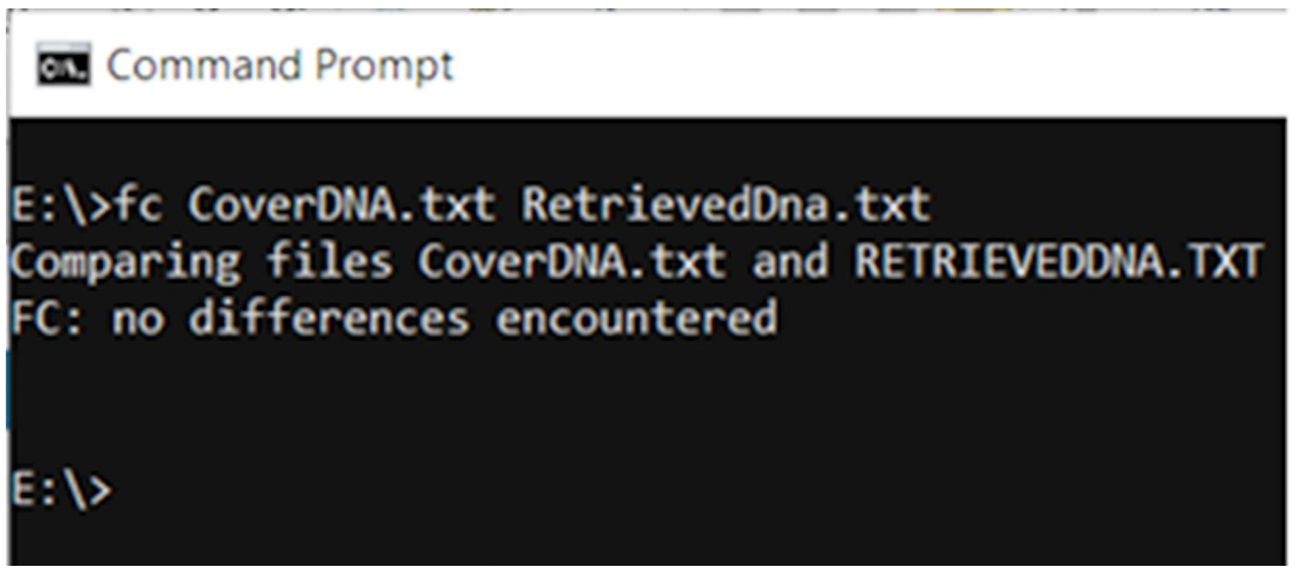
    After the execution of the i loop in the data extraction part of the Method, we will find R = R 2 . Hence, R = 11-11-11-10-11-11-10-00-10-11, DNA conversion of R is N r = TTTGTTGAGT. Thus, the scheme retrieves the hidden message and rebuilds the cover DNA/RNA.

5.5. Boosting Up Vulnerability

One noticeable point of the scheme is that the cover DNA is found at the first block of N ˜ x . The same is true in the case of RNA. According to the above example, cover DNA is TTTGTTGAGT. As the cover DNA is always found as a first block of N ˜ x , in case of stolen key, it cannot preserve the security of cover DNA. Therefore, we introduce a shuffling policy of blocks of N ˜ x . We have not explained that policy in the previous section due to better understanding. Moreover, it is not a necessary part of the algorithm for its functionality.
We know that N ˜ x consists of n 1 stego DNA blocks. Table 9 shows the method of shuffling n 1 stego blocks among themselves. The first column of the table shows the current block numbers of N ˜ x . These block numbers are randomly rearranged. After shuffling, block positions have changed. The second column shows the position of blocks after shuffling, e.g., the blocks, 0, 1, 2, 3, and so on, are moved to the 1, 0, 2, 0, … index positions, respectively. The indices of all blocks after their movements are tabulated at the third column. The fourth and fifth column show the equivalent binary of moved position and converted nucleotides of the binaries. These nucleotides are interpreted in a top-down manner, and thus, the read values are ACATAGAACGCATCTATTCTTGGTGGGACCGC. Say, it is N ˜ s . We make that N ˜ s as a part of stego key. In that case, S K will increase in size by more than 64 bits. Finally, N ˜ x will be modified by N ˜ x by N ˜ 3 N ˜ 0 N ˜ 2 N ˜ 1 , where ‖ stands for concatenation. Then, the new sequence will be as N ˜ x = GCTTTTATGA-TTTGTTGAGT-CGTGAAACGA-CACGCGGGTA.
At the receiver end, the decoder first separates N ˜ s from the last 32 nucleotides of S K . For this example, it is ACATAGAACGCATCTATTCTTGGTGGGACCGC. At that stage, it is necessary to know the number of blocks that the stego nucleotides contain. That could be part of a negotiated stego key or might be managed by adding two additional nucleotides. In our case, we communicate that information between encoder and decoder through stego key. Indeed, it is the cycle number, i.e., n. In our above example, we used 4 blocks. Hence, the decoder will separate first eight nucleotides of the ACATAGAACGCATCTATTCTTGGTGGGACCGC, i.e., ACATAGAA. The decimal conversion of that ACATAGAA will produce 1-3-2-0. That result states that the 2nd block, 4th block, 3rd block and 1st block are the reading sequences. The readers will generate N ˜ x by N ˜ 1 N ˜ 3 N ˜ 2 N ˜ 0 . Thus, N ˜ x = TTTGTTGAGT-CACGCGGGTA-CGTGAAACGA-GCTTTTATGA. From that stage, the process of extracting secrets and recovering cover DNA is explained in earlier discussions.

6. Result Analysis and Discussions

A good number of experiments were conducted on different DNA and RNA datasets, most of which were collected from NCBI datasets [4,5,6,7]. Rest of them was obtained by our developed program. Our generated DNAs were used to check whether the proposed method could be able to work on independent data set or not. We found no anomalies, i.e., the method worked successfully.
Among those datasets, results of seven datasets are presented in the following discussions. Table 10 states the properties of those seven datasets.
To use in our analysis, we produce several binary data of different length, as of Table 11. We assume these as a secret message and then implant these in various DNA and RNA dataset of Table 10.

6.1. Checking Reversibility

First, we allow the data embedment module to implant data bits of the confidential message, of Table 11, in DNA/RNA of Table 10. Thereafter, we execute the extraction module to retrieve data from the stego DNA/RNA and reconstruct the original cover DNA/RNA. Our system does it blindly, i.e., without taking any extra help from the decoder. The extracted message was stored in RetrivedMsg.txt, while the original message stream was saved to SecretMsg.txt file. We compare these two files using the file comparing function, named fc of DOS. We follow this procedure for the cover and extracted DNA as well. In both cases, no difference was encountered. That result of a DNA was shown in Figure 6. Thus, the proposed method proves its success in secret extraction and covers DNA reconstruction processes.
The method of calculating the error rate is shown in Equation (7). The equation is given just to measure the error rate if an error arises. As the fc command of DOS encounters no differences between cover DNA and extracted DNA in our case, the error rate is set to zero, as shown in Table 12.
E r r o   R a t e s = N o .   o f   E r r o r s L e n g t h   o f   N u c l e o t i d e s 100 %

6.2. Payload Comparison

The payload was determined by the number of bits that a scheme implants in a DNA or RNA sequence. In our experiment, the proposed scheme implants in about N r nucleotides. Therefore, at each cycle, the scheme implants | N r | × 2 bits and finally, payload tallies to ( | N r | × 2 ) × c for c time of data embedment, as showed in Equation (8). Again, as in Equation (9), capacity is a measure of bits that could be implantable per nucleotide.
P a y l o a d = ( | N r | × 2 ) × c
C a p a c i t y = P a y l o a d T o t a l   N u c l e o t i d e s = ( | N r | × 2 ) × c | N r | = 2 c
where | N r | stands for the number of cover nucleotides and c indicated the number of embedment cycles.
Table 13 presents the results of payload. Our method strongly dominates the other competing schemes. The same result is noted at Figure 7. Even single cycle execution ( c = 1 ) also implants a double of the [30] and three times of [31,32]. Every higher cycle increases that payload amount to twice that of the one immediately before.

6.3. Expansion

The methods that we studied, which are state-of-the-art methods, indicate that due to data embedment, the size of stego nucleotides increases. The method of computing the expansion rate is a process of measuring the ratio between the differences in length of stego and cover nucleotides and the cover nucleotides. For the proposed scheme, it is c × 100 % , as shown in Equation (10).
E R = ( | N ˜ x | | N r | ) | N r | × 100 % = ( c × | N r | ) | N r | × 100 % = c × 100
We observed that the stego DNAs other than the last cycle are in N ˜ x and the final stego DNAs are in N ˜ r . If we keep both the stego DNAs in the cloud, an intruder might feel interested to look for the secret message in the stego DNA due to the large size of stego DNA. Therefore, we propose to upload only N ˜ r at the cloud and to make N ˜ x as a part of S K . Thus, we minimize the expansion rate of stego DNA to 0%. Even then, the size of S K is L × n + 20 bits which is smaller than the competing method [30] because the length of S K in [30] is 2 × | M | + 136 . In fact, this 2 × | M | + 136 is about double of L × n + 136 .
Table 14 shows the results of the expansion rate. Our method presents dominating results. Although we executed our method for 16 cycles, for the purpose of the paper organization, only the results of the first three cycles are provided in Table 13 and Table 14.

6.4. Robustness

There are many steganalysis methods that try to detect stego contents in a cover medium [35,36]. Therefore, checking the robustness of a scheme is necessary.

6.4.1. Cracking Probability

To crack the concealed data in our method, an intruder first needs to guess S. To this end, the length of S should be guessed as well. Let the length of S be l, where 1 l | N r | × 2 . The total possibility of forming separate S is defined by Equation (11).
S N = l = 1 | N r | × 2 2 l
Note that, in practice, l is a very big number. Moreover, that cracking probability will increase for every subsequence cycle. It is hard to assume the probable number of executing cycles. However, for simplicity, we consider 16 execution cycles. Then, the cracking possibility (CP) will increase by more than 16 times. Again, there are 2 n possible messages which might be formed in the given length n, where n is the length of the message. Consequently, the cracking possibility C P increases and it is defined by Equation (12).
C P ( S , M , c ) = l = 1 | N r | × 2 2 l + n + 4
We have increased vulnerability by shuffling 16 blocks of N ˜ x . That shuffling will again enlarge the probable number by 2 16 . Consequently, the total cracking possibility will further increase and thus, the total C P will be 2 16 times that of Equation (12). After simplifying the exponential values, we can compute C P using Equation (13).
C P ( S , M , c , N ˜ x ) = l = 1 | N r | × 2 2 l + n + 20
The cracking probability is the inverse of the different possible cracking capabilities, i.e., cracking probability P is 1 / C P . Hence, we can now deduce the cracking probability P by Equation (14).
P ( S , M , c , N ˜ x ) = 1 l = 1 | N r | × 2 2 l + n + 20

6.4.2. Machine Learning

Nowadays, intruders apply various machine learning algorithms to guess whether a media contain stego contents or not. They even try to extract the secrets as well through their machine learning algorithms. To evaluate the robustness of our scheme, we implement a one-hot encoder for using nucleotides in a convolution neural network. The method first takes the cover nucleotides and the stego nucleotides of the proposed method, Rahman et al. [30], Hamed et al. [31] and Wang et al. [32] in five separate files. We first extracted the nucleotides from the cover file. As the nucleotides are one of ‘A’, ‘C’, ‘G’ and ‘T’, we generated four bits as one-hot codes for each nucleotide. ‘A’, ‘C’, ‘G’ and ‘T’ are used for label/class values. Thus, we had a long list of data where each one consisting of 4 bits. Suppose that this is X. Similarly, we have the same length of class labels, i.e., nucleotides. Let these data be Y. We divided both X and Y in a ratio of 9:1. Let the first 90% of data be t r a i n X and t r a i n Y . In the same way, let the remaining 10% of data be t e s t X and t e s t Y . We built a convolution neural network (CNN) model to train t r a i n X and t r a i n Y . Afterwards, we applied t e s t X to predict t e s t Y . We measured the accuracy in decoding the one-hot code. We performed the same tasks for the other four files, i.e., for the stego nucleotides of the proposed method, following Rahman et al. [30], Hamed et al. [31] and Wang et al. [32]. The results are demonstrated in Table 15. The table states that the accuracies in stego nucleotides are very close to those in cover. This means that detecting stego contents in a stego DNA sequence by deep learning is quite hard.
Another noticeable point is that the accuracy is 0 in Rahman and Wang for O u r D N A . 2 cover sequence. It happens as a result of the small size of the sequence. That sequence contains only 10 nucleotides. For such a small dataset, a deep learning or machine learning algorithm cannot provide accurate results. Rather, any result can be produced by a machine. Hence, it would not be rational to believe the accuracy of the other three pieces of data of the O u r D N A . 2 cover sequence as well.

6.5. Summary

As a summary, Table 16 summarizes the comparison results of the proposed scheme with two closely related works. Although, in our scheme, the expansion rate is 0%, it provides a notably higher payload than the others. The scheme creates stego DNA which is same as that of cover DNA by size. As a result, stego DNA does not demand extra space in the cloud. The cracking probability is also a considerable number and greater than the others. Thus, it ensures higher security. The proposed scheme works with an RNA sequence while the others do not. The proposed scheme can work on only a few of nucleotides, e.g., about 10 nucleotides, while the others cannot perform their operation on such small size of nucleotides. As the proposed scheme implants secrets in working DNA for multi-time, it has the ability to implant more bits in a small-sized DNA set than the others, even if the others implant on a large DNA set as well.

7. Conclusions

The proposed cyber-manufacturing system is very simple but effective. It would be easy for the industry to manufacture such devices. The research also provides strong data security, as well as enhances the embedding capacity. The proposed multi-time data embedment scheme allows an application to implant any number of bits of secret message in a small DNA sequence and even in a small portion of a DNA sequence, known as a DNA strand. Hence, a small memory is enough to make the scheme functional. Thus, this opens up a unique opportunity for data hiding-based healthcare applications as well as for the manufacturing industries.
Moreover, the scheme could be used in message communication, identifying a device and recognizing the source of data. It will work in both offline and in the cloud. This will be a very useful scheme for an organization whereby the organization works with DNA. The medical and criminology departments of a country work on DNA and/or RNA. They just have to manage a huge volume of information for their patients and criminals. It would be a very notable application to hide the large volume of their secrets in their official DNA/RNA. From a managerial point of view, this contribution will be a smart one in handling their data. In our future work, we hope to work more on manufacturing architecture. We will work to improve the hardware and software architectures of such cyber devices to make them more user-friendly, efficient and functional. Additionally, we intend to embed personal information and one’s DNA strand in a smart wearable device in our next research. Then, criminals and unknown dead bodies could be identified easily.

Author Contributions

M.N. and A.H.M.K. are the main contributors to this article. M.N. is working as a PhD student under the supervision of A.H.M.K.. This work is a contribution of PhD research work. M.R.H. and M.A.M. advise the other two authors at several phases of the implementation. To improve the figure's quality and organization of the article, they helped. Additionally, they did the proofreading of the written article and provided necessary suggestions to the two premier authors. All authors have read and agreed to the published version of the manuscript.

Funding

This research work is partially supported by University Grants Commission of Bandladesh through its research project and the Information and Communication Technology division of the Ministry of Post, Telecommunication and Information Technology of the Government of Bangladesh.

Institutional Review Board Statement

Not applicable.

Informed Consent Statement

Not applicable.

Data Availability Statement

We used data from the National Center of Biotechnology Information (NCBI) repository. Additionally, we generated some data that were not uploaded anywhere. However, that could be made available on request.

Acknowledgments

Kamal and Nahar work as the chief implementer of this research project. This project is funded by the University Grant Commission of Bangladesh through its Research and Expansion cell of Jatiya Kabi Kazi Nazrul Islam University. Nahar works as a PhD student under the supervision of Kamal and consequently, Kamal and Nahar work jointly in this research work. Nahar is a PhD fellow of the Information and Communication Technology division of the Ministry of Post, Telecommunication and Information Technology of the Government of Bangladesh. Both Kamal and Nahar are the key persons in this research work. Hence, the authors are pleased to acknowledge these two supports of the respective bodies.

Conflicts of Interest

There are no conflict of interest with this research work.

References

  1. Andronie, M.; Lǎzǎroiu, G.; Ştefǎnescu, R.; Uţǎ, C.; Dijmǎrescu, I. Sustainable, smart, and sensing technologies for cyber-physical manufacturing systems: A systematic literature review. Sustainability 2021, 13, 5495. [Google Scholar] [CrossRef]
  2. Chen, X.; Jin, R. Adapipe: A recommender system for adaptive computation pipelines in cyber-manufacturing computation services. IEEE Trans. Ind. Inform. 2020, 17, 6221–6229. [Google Scholar] [CrossRef]
  3. Song, J.; Wang, C.; Saudrais, C.; Swanson, M.K.; Greaney, E.A.; Moon, Y.B. Cyber-Manufacturing System Testbed Development: Adversarial Insider Manipulation. Procedia CIRP 2020, 93, 180–185. [Google Scholar] [CrossRef]
  4. Severe Acute Respiratory Syndrome Coronavirus 2 Isolate Wuhan-Hu-1, Complete Genome, GenBank: MN908947.3, Total Gene 29903. Available online: https://www.ncbi.nlm.nih.gov/nuccore/MN908947 (accessed on 12 August 2021).
  5. Lu, R.; Zhao, X.; Li, J.; Niu, P.; Yang, B.; Wu, H.; Wang, W.; Song, H.; Huang, B.; Zhu, N.; et al. Genomic characterisation and epidemiology of 2019 novel coronavirus: Implications for virus origins and receptor binding. Lancet 2020, 395, 565–574. [Google Scholar] [CrossRef]
  6. Severe Acute Respiratory Syndrome Coronavirus 2 Isolate Wuhan-Hu-1, Complete Genome, NCBI Reference Sequence: NC_045512.2, Total Gene 29903. Available online: https://www.ncbi.nlm.nih.gov/nuccore/NC_045512 (accessed on 12 August 2021).
  7. Mus Musculus 10 BAC RP23-383C2 (Roswell Park Cancer Institute (C57BL/6J Female) Mouse BAC Library) Complete Sequence, NCBI Reference Sequence: AC153526.13, Total Gene 200117. Available online: https://www.ncbi.nlm.nih.gov/nuccore/AC153526.13 (accessed on 12 August 2021).
  8. Kamal, A.H.M.; Islam, M.M. Facilitating and securing offline e-medicine service through image steganography. Healthc. Technol. Lett. 2014, 1, 74–79. [Google Scholar] [CrossRef]
  9. Kamal, A.H.M.; Islam, M.M. An image distortion-based enhanced embedding scheme. Iran J. Comput. Sci. 2018, 1, 175–186. [Google Scholar] [CrossRef]
  10. Lin, W.D.; Low, Y.H. Concept design of a system architecture for a manufacturing cyber-physical digital twin system. In Proceedings of the 2020 IEEE International Conference on Industrial Engineering and Engineering Management (IEEM), Singapore, 14–17 December 2020. [Google Scholar]
  11. Liu, X.F.; Shahriar, M.R.; Al Sunny, S.N.; Leu, M.C.; Hu, L. Cyber-physical manufacturing cloud: Architecture, virtualization, communication, and testbed. J. Manuf. Syst. 2017, 43, 352–364. [Google Scholar] [CrossRef]
  12. Ismail, S.M.; Said, L.A.; Radwan, A.G.; Madian, A.H.; Abu-Elyazeed, M.F. Generalized double-humped logistic map-based medical image encryption. J. Adv. Res. 2018, 10, 85–98. [Google Scholar] [CrossRef]
  13. Najafi, E.; Loukhaoukha, K. Hybrid secure and robust image watermarking scheme based on SVD and sharp frequency localized contourlet transform. J. Inf. Secur. Appl. 2019, 44, 144–156. [Google Scholar] [CrossRef]
  14. Chan, H.T.; Hwang, W.J.; Cheng, C.J. Digital Hologram Authentication Using a Hadamard-Based Reversible Fragile Watermarking Algorithm. J. Disp. Technol. 2015, 11, 193–203. [Google Scholar] [CrossRef]
  15. Wang, X.Y.; Wang, C.P.; Yang, H.Y.; Niu, P.P. A robust blind color image watermarking in quaternion Fourier transform domain. J. Syst. Softw. 2013, 86, 255–277. [Google Scholar] [CrossRef]
  16. Lee, S. Reversible Data Hiding for DNA Sequence using Multilevel Histogram Shifting. Hindawi Secur. Commun. Netw. 2018, 2018, 3530969. [Google Scholar] [CrossRef]
  17. Chung, K.L.; Huang, Y.H.; Yan, W.M.; Teng, W.C. Distortion reduction for histogram modification-based reversible data hiding. Appl. Math. Comput. 2012, 218, 5819–5826. [Google Scholar] [CrossRef]
  18. Lin, C.C.; Tai, W.L.; Chang, C.C. Multilevel reversible data hiding based on histogram modification of difference images. Pattern Recognit. 2008, 41, 3582–3591. [Google Scholar] [CrossRef]
  19. Rahman, M.S.; Khalil, I.; Yi, X. Reversible Biosignal Steganography Approach for Authenticating Biosignals using Extended Binary Golay code. IEEE J. Biomed. Health Inform. 2020, 25, 35–46. [Google Scholar] [CrossRef] [PubMed]
  20. Gujjunoori, S.; Amberker, B.B. DCT based reversible data embedding for MPEG-4 video using HVS characteristics. J. Inf. Secur. Appl. 2013, 18, 157–166. [Google Scholar] [CrossRef]
  21. Parah, S.A.; Ahad, F.; Sheikh, J.A.; Bhat, G.M. Hiding clinical information in medical images: A new high capacity and reversible data hiding technique. J. Biomed. Inform. 2017, 66, 214–230. [Google Scholar] [CrossRef]
  22. Kamal, A.H.M.; Islam, M.M. Boosting up the data hiding rate multi cycle embedment process. J. Vis. Commun. Image Represent. 2016, 40, 574–588. [Google Scholar] [CrossRef]
  23. Kamal, A.H.M.; Islam, M.M. Enhancing embedding capacity and stego image quality by employing multi predictors. J. Inf. Secur. Appl. 2017, 32, 59–74. [Google Scholar] [CrossRef]
  24. Bhalerao, S.; Ansari, I.A.; Kumar, A.; Jain, D.K. A reversible and multipurpose ECG data hiding technique for telemedicine applications. Pattern Recognit. Lett. 2019, 125, 463–473. [Google Scholar] [CrossRef]
  25. Islam, S.; Gupta, P. Effect of morphing on embedding capacity and embedding efficiency. Neurocomputing 2014, 137, 136–141. [Google Scholar] [CrossRef]
  26. Abdullah, A.A.; Eesa, A.S.; Abdo, A.M. New data hiding approach based on biological functionality of DNA sequence. Sci. J. Univ. Zakho 2019, 7, 184–189. [Google Scholar] [CrossRef]
  27. Hong, W.; Chen, T.S.; Luo, C.W. Data embedding using pixel value differencing and diamond encoding with multiple-base notational system. J. Syst. Softw. 2012, 85, 1166–1175. [Google Scholar] [CrossRef]
  28. Hong, W.; Chen, T.S. A novel data embedding method using adaptive pixel pair matching. IEEE Trans. Inf. Forensics Secur. 2012, 7, 176–184. [Google Scholar] [CrossRef]
  29. Wang, W.J.; Huang, C.T.; Wang, S.J. VQ applications in steganographic data hiding upon multimedia images. IEEE Syst. J. 2011, 5, 528–537. [Google Scholar] [CrossRef]
  30. Rahman, M.S.; Khalil, I.; Yi, X. A lossless DNA data hiding approach for data authenticity in mobile cloud based healthcare systems. Int. J. Inf. Manag. 2019, 45, 276–288. [Google Scholar] [CrossRef]
  31. Hamed, G.; Marey, M.; Amin, S.E.S.; Tolba, M.F. Hybrid randomized and biological preserved DNA-based crypt-steganography using generic N-bits binary coding rule. In Proceedings of the International Conference on Advanced Intelligent Systems and Informatics, Cairo, Egypt, 24–26 October 2016; Springer: Cham, Switzerland, 2016. [Google Scholar]
  32. Wang, Y.; Han, Q.; Cui, G.; Sun, J. Hiding messages based on DNA sequence and recombinant DNA technique. IEEE Trans. Nanotechnol. 2019, 18, 299–307. [Google Scholar] [CrossRef]
  33. Severe Acute Respiratory Syndrome Coronavirus 2 Isolate SARS-CoV-2/Human/USA/CA-CZB-22407/2021, Complete Genome, NCBI Reference Sequence: MW738481, Total Gene 29847. Available online: https://www.ncbi.nlm.nih.gov/nuccore/MW738481.1/ (accessed on 12 August 2021).
  34. Severe Acute Respiratory Syndrome Coronavirus 2 Genome Assembly, Chromosome: 1, NCBI Reference Sequence: OU055787.1, Total Gene 29817. Available online: https://www.ncbi.nlm.nih.gov/nuccore/OU055787 (accessed on 12 August 2021).
  35. Pevný, T.; Bas, P.; Fridrich, J. Steganalysis by subtractive pixel adjacency matrix. IEEE Trans. Inf. Forensics Secur. 2010, 5, 215–224. [Google Scholar] [CrossRef]
  36. Fridrich, J.; Kodovsky, J. Rich models for steganalysis of digital images. IEEE Trans. Inf. Forensics Secur. 2012, 7, 868–882. [Google Scholar] [CrossRef] [Green Version]
Figure 1. Cyber manufacturing: architecture and functionality. The proposed device has several sensors to generate pathological data. The device stores the sensed data in a memory unit after implanting them in a DNA sequence. The DNA sequence is generated from the demographic information of the owner. Each time, it senses the present health statistics through its sensors. Then, it compares the sensed data with the historical data. Historical data were saved earlier by implanting them in a DNA sequence.
Algorithms 15 00335 g001
Figure 2. Flowchart for generating Stego DNA. This is, indeed, the proposed data hiding method. The method converts nucleotides to binaries. It generates a secret key S for one time only. This could be the password of the owner. The method employs a binary form of the message M i , secret key S and the binary of nucleotides R to generate stego nucleotides. If the message length is too big to hide in nucleotides, the scheme repeats the process.
Algorithms 15 00335 g002
Figure 3. Message and cover DNA extraction process. This is an inverse method that extracts the secrets from the stego DNA and rebuilds the cover DNA sequence as well.
Algorithms 15 00335 g003
Figure 4. Hardware architecture: Processing unit collects information from sensors. The processing unit then extracts the DNA sequence from the main memory. Then retrieve the historical and other data from the DNA sequence. The processing unit compares the sensor’s current data with the older one and signals accordingly. Updating the historical data with sensed information, the processing unit again implants that in the original DNA sequence. Finally, the processing unit sends back the stego DNA sequence to the main memory.
Algorithms 15 00335 g004
Figure 5. Signaling Unit: It generates one of the five signals based on the comparison of sensed data and the extracted historical data. A mathematical function f is used to generate one of the numbers from the set 1, 2, 3, 4. Here, f = 1 refers to gentile notification, which means that there is no problem. Moderate notification, i.e., f = 2, is generated for some level in changes of sensed data. f = 3 is generated to alarm the user about their health condition. When signaling unit measure f = 4, it automatically calls a doctor. For f = 5, the signaling unit sends the latest report and the historical data to the designated doctor.
Algorithms 15 00335 g005
Figure 6. Checking the reversibility of the proposed method. Here, we first save the cover and stego nucleotides in two different files. Then, we rebuild the cover DNA sequence from the stego DNA sequence using our proposed algorithm. The rebuilt DNA sequence is saved to another file. The DOS operating system has a special function named fc, which is used to compare two files. We used the fc command to compare the files containing cover and rebuilt cover DNA sequences. The fc command encountered no differences. That means that the two files contain similar information. Thus, proof of reversibility is obtained.
Algorithms 15 00335 g006
Figure 7. Payload analysis of different schemes. Here, we presented payloads of three competing methods and the results of our method for three different cycles. In the whole dataset, the proposed scheme gives higher payloads. The payload increased along with the higher embedding cycle.
Algorithms 15 00335 g007
Table 1. Nucleotides to binary conversion and vice versa.
NucleotidesBinary Values
A00
C01
G10
T11
Table 2. Stego key’s elements and its length.
SK
N ˜ x LnS
L × ( n 1 ) 16 bits4 bits L bits
T o t a l : ( L × n + 20 ) bits
Table 3. Results of execution cycle 1 in data implantation module.
N r TTTGTTGAGT
R11111110111110001011
S00001111000111000001
M 1 10110111100011100110
Using Equation (1): R ˜ = R ˜ S M i
R ˜ 01000110011010101100
Table 4. Results of execution cycle 2 in data implantation module.
R01000110011010101100
S00001111000111000001
M 2 00100111011101110101
R ˜ 01101110000000011000
Table 5. Results of execution cycle 3 in data implantation module.
R01101110000000011000
S00001111000111000001
M 3 11111110001011100001
R ˜ 10011111111100111000
Table 6. Results of execution cycle 1 in data extraction module.
R 1 10011111111100111000
R 2 01101110000000011000
S00001111000111000001
Equation (5): M 1 = R 1 R 2 S
M 1 11111110001011100001
Table 7. Results of execution cycle 2 in the data extraction module.
R 1 01101110000000011000
R 2 01000110011010101100
S00001111000111000001
Equation (5): M 1 = R 1 R 2 S
M 1 00100111011101110101
Table 8. Results of execution cycle 3 in the data extraction module.
R 1 01000110011010101100
R 2 11111110111110001011
S00001111000111000001
Equation (5): M 1 = R 1 R 2 S
M 1 10110111100011100110
Table 9. Shuffling stego blocks.
Block No.of N ˜ x After Shuffling Block’s No.Current Indexof Original Block N ˜ x Binary of Current PositionEquivalent Nucleotides of Binaries
0310001AC
1030011AT
2220010AG
3100000AA
4560110CG
51440100CA
64131101TC
79121100TA
813151111TT
91570111CT
1012141110TG
1111111011GT
127101010GG
13681000GA
141050101CC
15891001GC
Table 10. Sample DNA sequences that are used as cover medium.
Genome BankGenome IDDescriptionNo. of Nucleotides
MN908947.3RNA1coronavirus 2 isolateWuhan-Hu-1 [4]29,903
NC045512.2RNA2coronavirus 2 isolateWuhan-Hu-1 [6]29,903
MW738481RNA3coronavirus 2 isolateSARS-CoV-2/human/USA/CA-CZB-22407/2021 [33]29,847
OU055787.1RNA4coronavirus 2 genome assembly,
chromosome: 1 [34]
29,817
AC153526DNA1Mus musculus 10BAC RP23-383C2 [7]200,117
OurDNA.1DNA2It was producedby a program100,000
OurDNA.2DNA3We producedmanually10
Table 11. Length of tested of message.
Message NameDescriptionLength in Bits
OurMsg.1We produced it with our program.800,000
OurMsg.2We produced it manually.60
OurMsg.3We produced it with our program.2000
OurMsg.4We produced it with our program.20,000
OurMsg.5We produced it with our program.100,000
OurMsg.4We produced it with our program.200,000
Table 12. Error rate of proposed method.
Genome BankNo. of NucleotidesError Rates in %
MN908947.329,9030
NC045512.229,9030
MW73848129,8470
OU055787.129,8170
AC153526200,1170
OurDNA.1100,0000
OurDNA.2100
Table 13. Payload of the proposed method for different sequences.
Genome BankHamedWangRahmanProposed
1Cycle2Cycle3Cycle
MN908947.39676996529,00058,000116,00017,4000
NC045512.29786996529,00058,000116,000174,000
MW7384819569994329,00058,000116,000174,000
OU055787.19235993629,00058,000116,000174,000
AC15352669,67466,695200,000400,000800,0001,200,000
OurDNA.134,36733,329100,000200,000400,000600,000
OurDNA.23310204060
Table 14. Expansion rate of methods.
Genome BankHamed %Wang %Rahman %Proposed %
1Cycle2Cycle3Cycle
MN908947.317.420051000
NC045512.217.720051000
MW73848116.620045000
OU055787.116.120043000
AC15352617.920087000
OurDNA.117.820097000
OurDNA.216.920089000
Table 15. Decoding accuracy of CNN.
SequenceCoverProposedHamedRahmanWang
AC15352651.7948.8348.8348.8048.79
MN908947.348.3748.4048.4048.6448.24
MW73848147.2947.3947.2647.5747.20
NC045512.248.3748.4048.3248.6448.20
OU055787.148.0948.1448.1147.3047.96
OurDNA.136.7736.7936.8336.9636.89
OurDNA.233.3333.3350.0000
Table 16. Comparison between the proposed scheme and the related works.
CriteriaProposed SchemeRahman [30]Hamed [31]Wang [32]
Payload ( | N r | × 2 ) × c L l L 1 3 N r 1 3 N r
ReversibilityYesYesYesYes
Expansion ExistNoYesYesNo
PreserveDNA/RNACharacteristicsYesYesYesYes
CrackingProbability (P)P = Equation (14)P > Equation (14)P > Equation (14)P > Equation (14)
Adaptive withEncrypted Dataand DNA/RNAYesNot saidNot saidYes
BlindYesYesYesYes
Depends onPublic DNAData SetNoNoNoNo
Multi-TimesEmbedmentYesNoNoNo
Can Work onSmall DatasetYesNoNoNo
Shifting performedin stego keyYesNoNoNo
Cover DNAguessableNoYesYesNo
Uses RNAYesNoNoNo
Cover and StegoLength same?YesNoNoYes
UsesReference DNANoNoNoYes
UsesReference KeyNoYesNoNo
Use stego keyYesYesYesYes
Publisher’s Note: MDPI stays neutral with regard to jurisdictional claims in published maps and institutional affiliations.

