Article

Optimal Coronavirus Optimization Algorithm Based PID Controller for High Performance Brushless DC Motor

by
Mohamed A. Shamseldin
Mechanical Department, Faculty of Engineering, Future University in Egypt, Cairo Governorate 11835, Egypt
Algorithms 2021, 14(7), 193; https://doi.org/10.3390/a14070193
Submission received: 24 April 2021 / Revised: 17 May 2021 / Accepted: 29 May 2021 / Published: 25 June 2021
(This article belongs to the Special Issue Algorithms for PID Controller 2021)

Abstract

:
This paper presents an efficient coronavirus optimization algorithm (CVOA) to find the optimal values of the PID controller to track a preselected reference speed of a brushless DC (BLDC) motor under several types of disturbances. This work simulates how the coronavirus (COVID-19) spreads and infects healthy people. The initial values of PID controller parameters consider the zero patient, who infects new patients (other values of PID controller parameters). The model aims to simulate as accurately as possible the coronavirus activity. The CVOA has two major advantages compared to other similar strategies. First, the CVOA parameters are already adjusted according to disease statistics to prevent designers from initializing them with arbitrary values. Second, the approach has the ability to finish after several iterations where the infected population initially grows at an exponential rate. The proposed CVOA was investigated with well-known optimization techniques such as the genetic algorithm (GA) and Harmony Search (HS) optimization. A multi-objective function was used to allow the designer to select the desired rise time, the desired settling time, the desired overshoot, and the desired steady-state error. Several tests were performed to investigate the obtained proper values of PID controller parameters. In the first test, the BLDC motor was exposed to sudden load at a steady speed. In the second test, the continuous sinusoidal load was applied to the rotor of the BLDC motor. In the third test, different operating points of reference speed were selected to the rotor of the BLDC motor. The results proved that the CVOA-based PID controller has the best performance among the techniques. In the first test, the CVOA-based PID controller has a minimum rise time (0.0042 s), minimum settling time (0.0079 s), and acceptable overshoot (0.0511%). In the second test, the CVOA-based PID controller has the minimum deviation about the reference speed (±4 RPM). In the third test, the CVOA-based PID controller can accurately track the reference speed among other techniques.

1. Introduction

Nowadays, the industrialized world needs good accuracy with fast manipulation [1]. Therefore, a high-performance actuator with an efficient control system becomes essential [2,3]. The brushless DC (BLDC) motor considers a permanent magnet synchronous machine that gives the advantage of the high starting torque and wide range of speeds [4,5]. Also, the construction simplicity of the BLDC motor drive system offers several advantages not introduced with brushed DC motors in terms of low rotor inertia and size [6,7].
Currently, the BLDC motor can be utilized in several engineering applications such as unmanned aeronautical vehicles (UAVs), industrial robots, CNC machines, electric vehicles, and servomechanism systems [8,9].
The conventional PID controller uses on a wide scale in industrial applications due to its simplicity, reliability, and the easy tuning of its parameters [10]. The challenge of a conventional PID controller is the selection of the proper parameters for a certain application [11,12]. There are several techniques to find the PID controller parameters such as trial and error and Ziegler and Nichols methods [13,14]. However, these previous techniques give an approximate solution. Currently, optimization techniques can be used to find the optimal values of the PID controller parameters [15,16]. There are different types of optimization techniques such as Genetic Algorithm (GA) which have been employed successfully to solve complex optimization problems, Particle Swarm Optimization (PSO), Ant Colony optimization, and Harmony Search (HS) optimization [17,18].
The coronavirus (COVID-19) is considered an unknown respiratory virus, revealed in humans in December 2019, that has spread worldwide with more than 10 million infected people so far. This virus can infect people and these people can either die, infect other people, or recover after the infection. Vaccines and the immune defense system usually fight the disease and help to alleviate their effects while an individual is still infected [19]. This behavior can be modeled by a SIR model, consisting of three categories of individuals: S presents the number of susceptible, I stands for the number of infectious, and R is the number of recovered. Metaheuristics need to deal with huge search spaces, even infinite for the continuous cases, and must find suboptimal solutions in reasonable execution times [20].
The fast propagation of the coronavirus along with its ability to infect most of the countries in the world rapidly has inspired the novel metaheuristic proposed in this work, named Coronavirus Optimization Algorithm (CVOA). The proposed CVOA is used to find the optimal parameters for the PID controller. The vaccines stand for the used objective function which can treat the infected patients. A study case is included in this work to discuss the CVOA performance. CVOA has been used to find the optimal values for the PID controller parameters based on a multi-objective function that contains the desired rise time, desired settling time, desired maximum overshoot, and desired steady-state error. The purpose of the control system is to accurately track a preselected reference speed for BLDC motor under different types of loads.
A Comparative study using Grey Wolf Optimizer (GWO), Particle Swarm Optimization (PSO), and Genetic Algorithms was presented in [21]. The results showed that the proposed GWO algorithm has a lower root mean square compared to PSO and GA, and therefore, it could be an effective method for optimal PID controllers for power converters applications.
The position control of BLDC motor using HS Algorithm optimization technique was demonstrated in [22]. It demonstrates that the HS method can improve the dynamic performance of the system in a better way.
The design of a PSO optimized PID controller for the process liquid level control was illustrated in [23]. The computer simulation results show far better settling time and peak values with PSO optimized PID control, thus ensuring overall higher efficiency.
The performance comparison of Moth-Flame Algorithm (MFO) and PSO for optimal tuning the fractional order fuzzy PID controller for A DC-DC boost converter was designed in [24]. The MFO method is helpful to select the best values of fractional order fuzzy PID Controller for a DC-DC boost converter.
The paper is prepared as follows. Firstly, the BLDC motor dynamic model is presented. Secondly, CVOA is explained. Thirdly, the proposed CVOA based PID controller is demonstrated. Fourthly, the simulation results are illustrated. Finally, the conclusion is discussed.

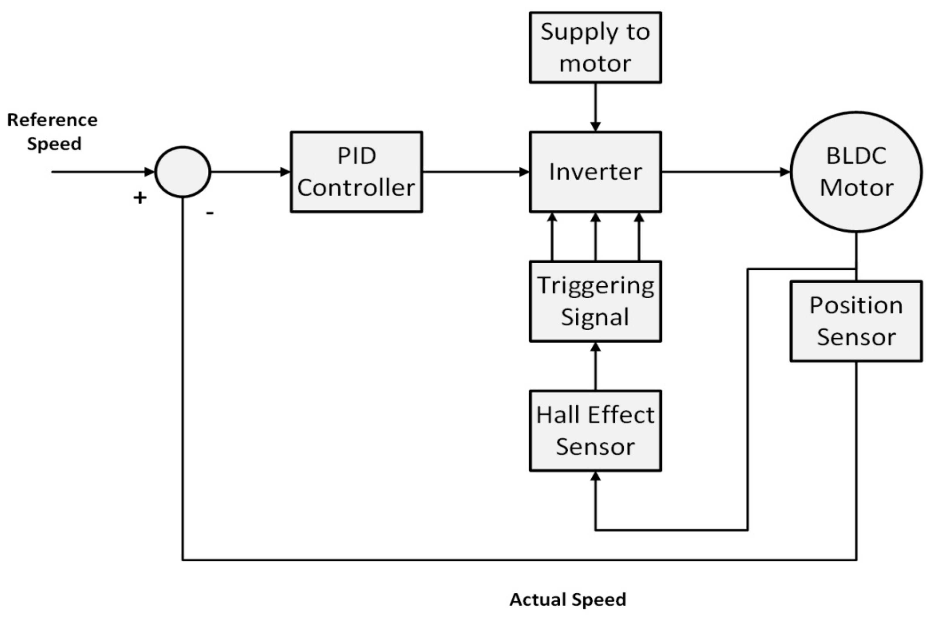
2. BLDC Motor Dynamic Model

The transfer function considers one of the most important techniques of control theory. Some control design and analysis methods, such as the root-locus method and the frequency-response method, are also developed based on the system transfer function. Usually, a 3-phase BLDC motor is connected by six electronic switches (power transistors) to produce a 3-phase voltage simultaneously to a full-bridge configuration power converter. The switching sequence can be adjusted by the position sensor [25].
The cases of rotor position are monitoring using three hall sensor devices. The hall sensors provide the information to the decoder block to create the sign of reference current signal vector to the back electromotive force (BEMF) [26].
To operate the motor in the opposite direction, the current is altered in the reverse direction or the switching order of the controller is changed. The controlled DC supply value depends on the PID controller output to can track a preselected speed profile [27].
The inverter used to transform the DC voltage to AC voltage likewise has a DC voltage converter to switch DC to this framework. Figure 1 demonstrates the main components of the BLDC motor drive system [28].
The state-space equation method is one of the most important analysis methods in modern control theory. The state-space method is becoming more and more popular in designing control systems with the fast development of computer techniques. The state-space model of the BLDC motor can be considered as Equations (1) and (2) [1].
i a . i b . w m . θ m . = R L 0 0 0 0 R L 0 0 0 0 B v J 0 0 0 1 0 i a i b w m θ m + 2 3 L 1 3 L 0 1 3 L 1 3 L 0 0 0 1 J 0 0 0 v a b _ e a b v a b _ e a b T e _ T L
i a i b i c w m θ m = 1 0 0 0 0 1 0 0 1 1 0 0 0 0 1 0 0 0 0 1 i a i b w m θ m
The vAB and vBC consider line input voltage. The ia and ib are the phase current through BLDC stator winding. The eAB and eBC stand for the equivalent line back emf. The R is the phase resistance of the winding. The L is the phase inductance of winding. The rotor moment of inertia is J while the rotor speed is ω. The TL is the load torque and Te is the electrical torque. The Ke and KT are the coefficient of lineback-EMF and the coefficient of line torque constant, respectively. Recently, the Bv stands for the viscous friction coefficient.
The parameters of the BLDC motor are listed in Table 1.
Figure 2 demonstrates the open-loop dynamic response of the BLDC motor drive system model. The no-load rotor speed stabilizes at 4000 RPM through 0.04 s. A fixed 50% of rated torque was applied on the motor shaft at time 0.1. Due to the sudden load, the corresponding rotor speed will be reduced to 3200 RPM. This behavior of the BLDC model indicates that the model was developed correctly.
Figure 3 shows the corresponding phase current of the BLDC motor. Usually, the starting current of the BLDC motor is very high and decreases to zero in the case of no-load. it provides this fact where the starting current reaches 18 Ampere and decays to zero at stabilizes the rotor speed. Besides, it can noted that the phase current will be increased at time 0.1 s to ±2.5 A due to the sudden load.

3. Control Techniques

The conventional PID controller is executed in various fields of engineering applications owing to its simplicity, reliability, and flexibility in tuning its parameters. The transfer function of the PID controller is k(s) = Kp + Ki/s + Kd s, where Kp, Ki, and Kd are proportional, integral, and differential gains, respectively. The function of each part of a PID controller can be described as follows: the proportional part decreases the error responses of the system to disturbances, the integral part rejects the steady-state error, and finally, the derivative part diminishes the dynamic response and improves the system stability.
The problem in the PID controller is to choose the three parameters to be suitable for the controlled plant. There are many methods to define the parameters of PID controller such as try and error and Ziegler-Nichols methods but most of these methods are rough roads. Therefore, this paper presents a novel CVOA methodology to find the optimal values of the PID controller.

3.1. GA Based PID Controller

A Genetic Algorithm (GA) is considered as a useful optimization tool to search and optimize several parameters of control systems and scientific problems. As such, this paper uses the GA to optimize the PID controller parameters based on a certain objective function. The important step is to encode the problem into suitable GA chromosomes and then build the population. The previous works recommend 20 to 100 chromosomes in one population. The higher chromosome number gives us a better chance to get the optimal results. However, the execution time is a barrier to increasing the number of chromosomes. So, this work uses 80 chromosomes in each generation [3,29].
Each chromosome covers three parameters Kp, Ki, and Kd with value, bounds varied depend on the objective function used. The initial values of Kp, Ki, and Kd are determined from the Ziegler–Nichols rule, to get a better result.
The population in each generation is represented by an 80 × 4 matrix as obvious in Equation (3), depends on the number of the chromosome in population.
K p 1 K i 1 K d 1 J t 1 K p 2 K i 2 K d 2 J t 2 K p n K i n K d n J t n
where n: number of chromosomes.
Each row is one chromosome that comprises Kp, Ki, and Kd values then the last column is added to accommodate fitness values (Jt) of corresponding chromosomes [4,30]. The final values of Kp, Ki, and Kd are determined by minimizing a certain objective function. Many objective functions may be used for this purpose. In this work, the objective function in Equation (11) is considered [31].

3.2. HS Based PID Controller

Harmony Search (HS) was developed by Geem et al. in 2001. HS depends on the aesthetic quality which can be improved by adjusting the pitch of each musical instrument. Also, the objective function value determines the quality of the decision variables [32].
In the music improvisation process, all players’ sound pitches within range join together to achieve one harmony. If all pitches achieve good harmony each player stores in his memory that experience and the possibility to achieve a good harmony is increased in the next iterations [33].
The same thing occurs in the optimization; the initial solution is generated randomly from decision variables within the possible range. If the objective function values of these decision variables are acceptable to achieve a promising solution, then the possibility to reach a good solution is increased in the next iterations [34].
The initial population of Harmony Memory (HM) is generated randomly. HM consists of Harmony Memory Solution (HMS) vectors where
x j = [ K p j , K i j   a n d   K d j ] , j = 1 , ..... , H M S
The HM is filled with HMS vectors as follows [35]:
H M = K p 1 K i 1 K d 1 J t 1 K p 2 K i 2 K d 2 J t 2 . . . . . . . . . . . . K P H M S K i H M S K d H M S J t H M S
The Harmony Memory Consideration (HMC) rule, for this rule a new number r1 is generated within the range [0 1]. If r1 < HMCR, where HMCR is the harmony memory consideration rate, then the first decision variable in the new vector X j n e w is chosen randomly from the values in the current HM as follows [36]:
x j n e w = x j , x j { x 1 , x 2 , x 3 ..... , x H M S J }
The obtained decision variables from the harmony memory consideration rule are further examined to determine if it needs to pitch adjustment or not. A new random number r2 is generated within the range [0 1]. If r2 < PAR, where PAR is a pitch adjustment rate, then the pitch adjustment decision variable is calculated as follows:
x j n e w = x j ± r a n d ( 0 , 1 ) . B W
where BW is a bandwidth factor, which is used to control the local search around the selected decision variable in the new vector. Random initialization rule, If the condition r1 < HMCR fails, the new first decision variable in the new vector X j n e w is generated randomly as follows:
x j n e w = L x + U X L X .   r a n d ( 0 , 1 )
where LX and UX are the lower and upper bound for the given problem. After the harmony vector X n e w is generated, it will substitute the worst harmony vector X worst in the harmony memory if its objective function value is better than the objective function value of the worst harmony vector.

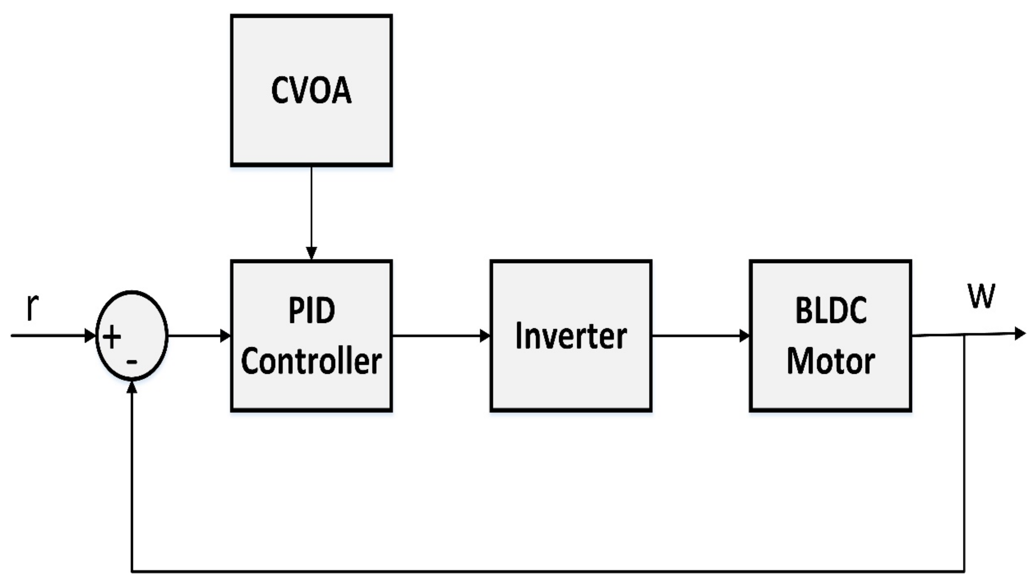
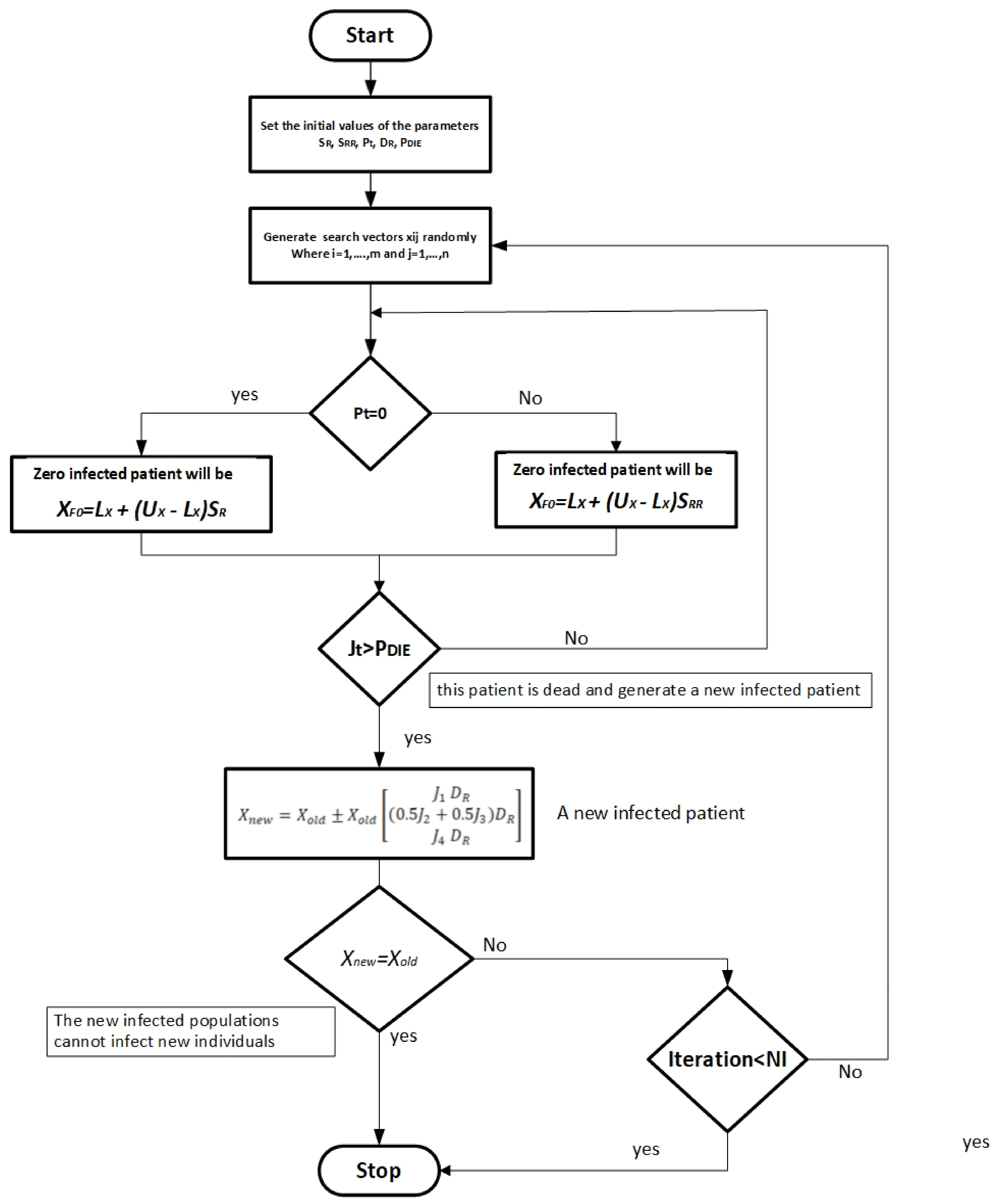
3.3. CVOA Based PID Controller

There are several bioinspired metaheuristics to deal with optimization problems. Although CVOA has been considered to optimize any type of optimization problem, this section focused on optimization algorithms used to find the optimal value of the PID controller parameters. The first step, generation of the initial population. The initial population (zero patient) contains one individual vector. As in the coronavirus epidemic scenario, it recognizes the first human being infected [37].
In the second step, the disease spread depends on the behavior of one individual vector (zero patient), several cases can be considered. The first case is that some of the infected individuals die. The possibility of death is according to the coronavirus death rate. Such individuals can no longer infect new individuals. The second case that is the individuals surviving the coronavirus will infect new individuals (intensification). Therefore, two types of disease propagation are considered, according to a given probability for ordinary spreaders. Infected individuals will infect new ones according to the rate spreading rate, while if the rate of coronavirus spread is high, the infected individuals will infect new ones according to the coronavirus super spreading rate. Both ordinary and super-spreader individuals can follow and find solutions quite dissimilarly. Therefore, individuals have a probability of traveling thus allowing them to spread the disease to solutions that may be quite different.
The third step consists of modernizing populations. Three populations are preserved and updated for each generation.If any individual dies, it is added to this population and can never be used again. After each iteration, infected individuals (after spreading the coronavirus according to the previous step) are sent to the recovered population. It is known that there is a reinfection probability. Hence, an individual fitting to this population could be re-infected at any iteration provided that it matches the reinfection criterion.
Another condition must be measured since individuals can be isolated simulating they are executing the social distancing procedures. For ease, it is considered that an isolated individual is sent to the recovered population as well when meeting an isolation probability.
Recently, a newly infected population has emerged. This population collects all individuals infected at each iteration, according to the procedure described in the previous steps. It is possible that repeated new infected individuals are created at each iteration and, consequently, it is recommended to eliminate such repeated individuals from this population before the next iteration starts running. The vaccines are considered as the used objective function, which can treat the infected population [19].
The fourth step is the stop criterion. One of the most important features of the proposed algorithm lies in its capability to end without the need of controlling any parameter. This situation occurs because the recovered and dead populations are constantly increasing as time goes by, and the newly infected population cannot infect new individuals. It is estimated that the number of infected individuals increases for a certain number of iterations. However, from a particular iteration on, the size of the newly infected population will be smaller than that of the current one because recovered and dead populations are too big, and the size of the infected population decays over time.
The initial population contains the upper and lower values of the PID controller parameters as shown in Equations from (3) to (5)
X = K p 0 K i 0 K d o . . . . . . . . . K p n K i n K d n
L X = [ K p 0 K i 0 K d 0 ]
U X = [ K p n K i n K d n ]
The performance of each row will be investigated according to the objective function in Equation (6). The poor performance specifies the infected population, which has the possibility to die. While the good performance indicates the recovered population from corona antivirus.
J t = j 1 + j 2 + j 3 + j 4 4
J 1 = t r t r d t r d
J 2 = t s t s d t s d
J 3 = t e s s t e s s d t e s s d
J 4 = O S O S d O S d
where (trd) is the desired rise time and (tr) is the measured rise time, (OSd) is the desired maximum overshoot and (OS) is the actual overshoot, (tsd) is the desired settling time and (ts) is the determining settling time, and (essd) is the desired steady-state error and (ess) is the estimated steady-state error.
It can be noted that objective function attempts to satisfy the designer using four sub-objective functions. The first sub-objective function focuses on improving the rise time of the overall drive systems. The second sub-objective function attempts to reduce the settling time. The third sub-objective function measures the steady-state error. The fourth sub-objective function investigates the required overshoot. The value of each sub-objective function ranges from zero to one. So, the overall objective function considers the average of the sum of four sub-objective functions. Figure 4 shows the CVOA offline tuning system with the BLDC motor drive system.
The first step investigates the Probability of travel If Pt = 0 then the type of spreading is SR = (0 to 0.5). In case of Pt = 1 then the type of spreading SRR = (0.5 to 1). In the second step, the zero infected patient If Pt = 0 will become as follows:
X F O = L X + U X L X S R
If zero infected patient If Pt = 1.
X F O = L X + U X L X S R R
The third step investigates if Jt > PDIE then this patient is dead and generates a newly infected patient. In the case of Jt < PDIE then the newly infected patient will be as follows:
X n e w = X o l d ± X o l d J 1 . D R 1 2 ( J 2 + J 3 ) . D R J 4 . D R
The optimization will be stopped if (Xnew = Xold) where the newly infected populations cannot infect new individuals. If the number of iteration ended before this previous condition. the CVOA cannot give the optimal solution. Therefore, to obtain the optimal parameters of PID controller must be (Xnew = Xold) to guarantee the global solution.
Table 2 demonstrates the used CVOA parameters through offline optimization.
The objective function has been minimized subjected to:
K p min K p K p max K i min K i K i max K d min K d K d max
The upper and lower limits of PID controller parameters as the following.
L X = [ K p min K i min K d min ]
U X = [ K p max K i max K d max ]
Best Fitness values are plotted against generations or number of iterations to get the convergence characteristic shown in Figure 5.
The sequence flow chart of optimization as shown in Figure 6.

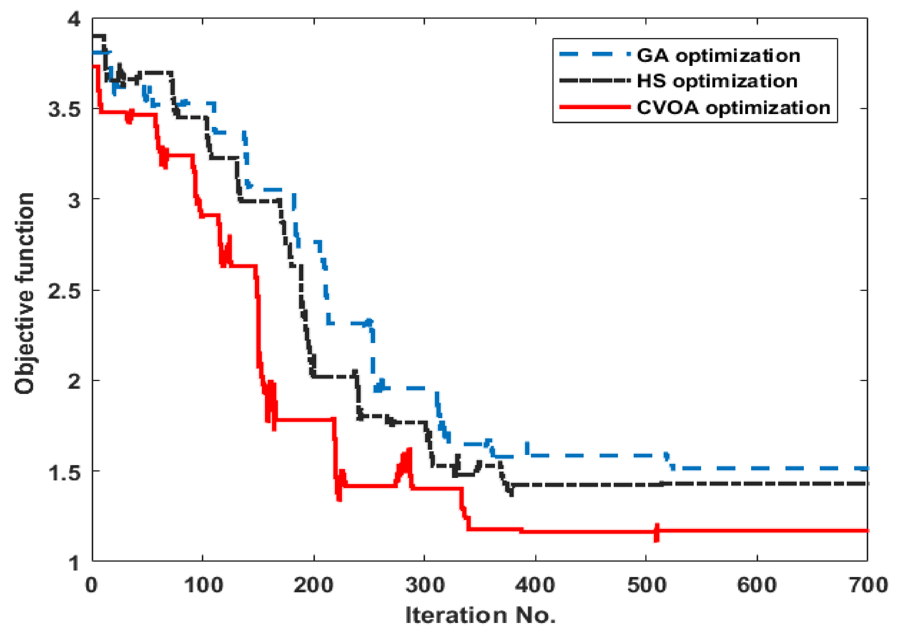
3.4. Optimization Results

This section presents the results of the optimization of each PID controller. It can be noted that Table 3 gives different values of the PID controller for each optimization technique. The obtained three different PID controllers were applied to the BLDC motor to investigate the performance and robustness of each control technique.
This results in faster convergence for the solutions in the CVOA technique. GA has no such guidance mechanism. Better solutions only pass the information when they participate in the crossover with some other chromosomes. Also, the updated generation does not directly depend on the value of the objective function in both GA and HS. In contrast of the updated law of the CVOA technique in Equation (18) has a direct relation with the objective function where the value of the objective function can determine and estimated the new generation value as follows:
Xnew(1) = Kp = F(J1)
Xnew(2) = Ki = F(0.5.J2 + 0.5.J3)
Xnew(3) = Kd = F(J4)
From Equations (22) to (24), we can note that when J1, J2, J3, and J4 close to zero the Xnew = Xold to achieve the stop criterion (the newly infected populations cannot infect new individuals). Also, the DR parameter is randomly determined by the immunity of individuals which is an important factor to estimate the newly infected individuals.
GA does not use memory to keep track of the solutions throughout different generations. Modern machines are good with mathematical computations. CVOA and HS technique has an inherent tendency to exploit this advantage because all the computations and procedures in CVOA are purely mathematical. However, GA has procedures like crossover, mutation which are not purely mathematical which makes GA more time-consuming than CVOA.

4. Simulation Results

This section of the paper shows the performance of the BLDC motor at different types of PID controllers. The first type is based on the GA. the second type is based on the HS. The third type is based on the proposed CVOA. Besides, several tests will be performed. The first test is the speed regulation at sudden load. The second test is the speed regulation at sinusoidal load. The third test is the speed tracking at different operating points at the reference speed.

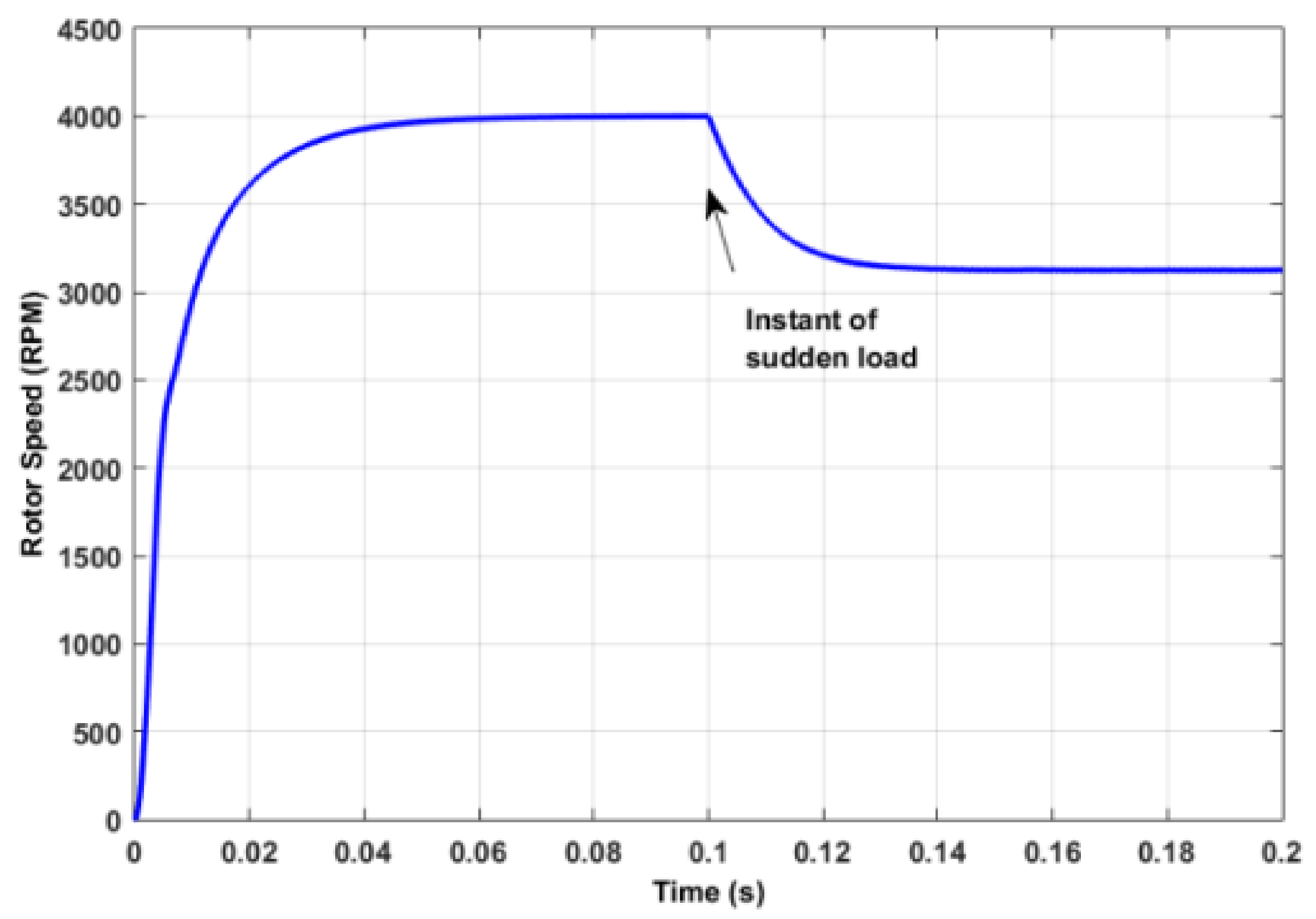
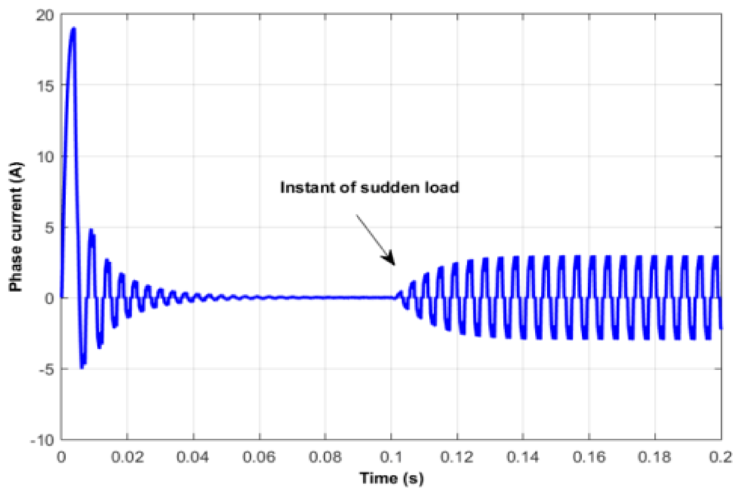
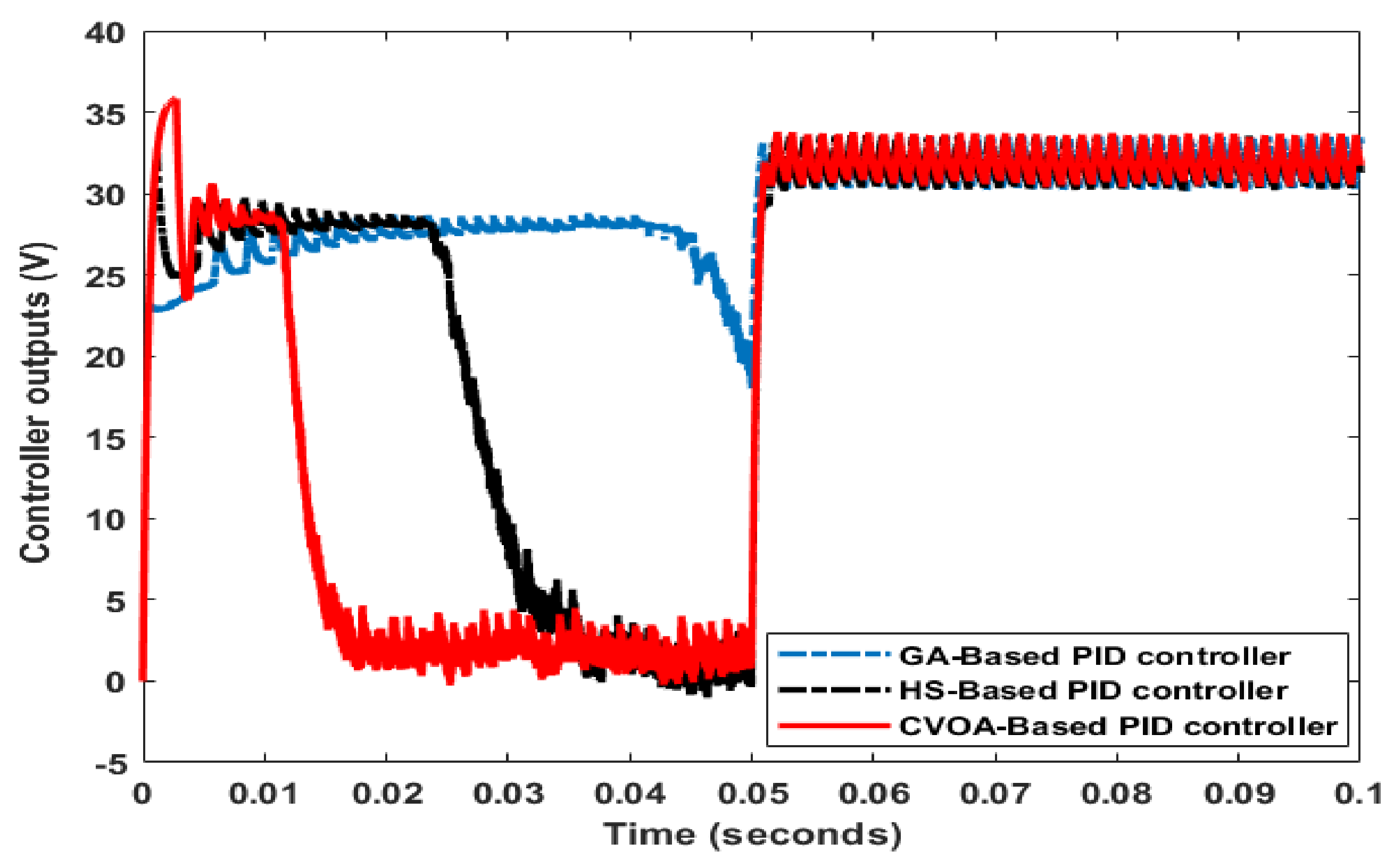
4.1. Speed Regulation at Sudden Load Case

Figure 7 shows that the CVOA-based PID controller can track the reference speed rapidly compared to the GA-based PID controller and HS-based PID controller. Besides, the CVOA-based PID controller can absorb the sudden load disturbance at an instant of 0.05 s in a short time.
Table 4 summarizes the performance of each control technique. It can be noted that the CVOA-based PID controller has the least rise time and settling time. Also, the steady-state of the proposed CVOA is very small compared to other techniques algorithm.
Figure 8 demonstrates the corresponding controller output of each control technique. It is clear that the CVOA-based PID controller can detect rapidly any change in BLDC motor dynamic. In addition, the CVOA-based PID controller has a step change value at a sudden load test.

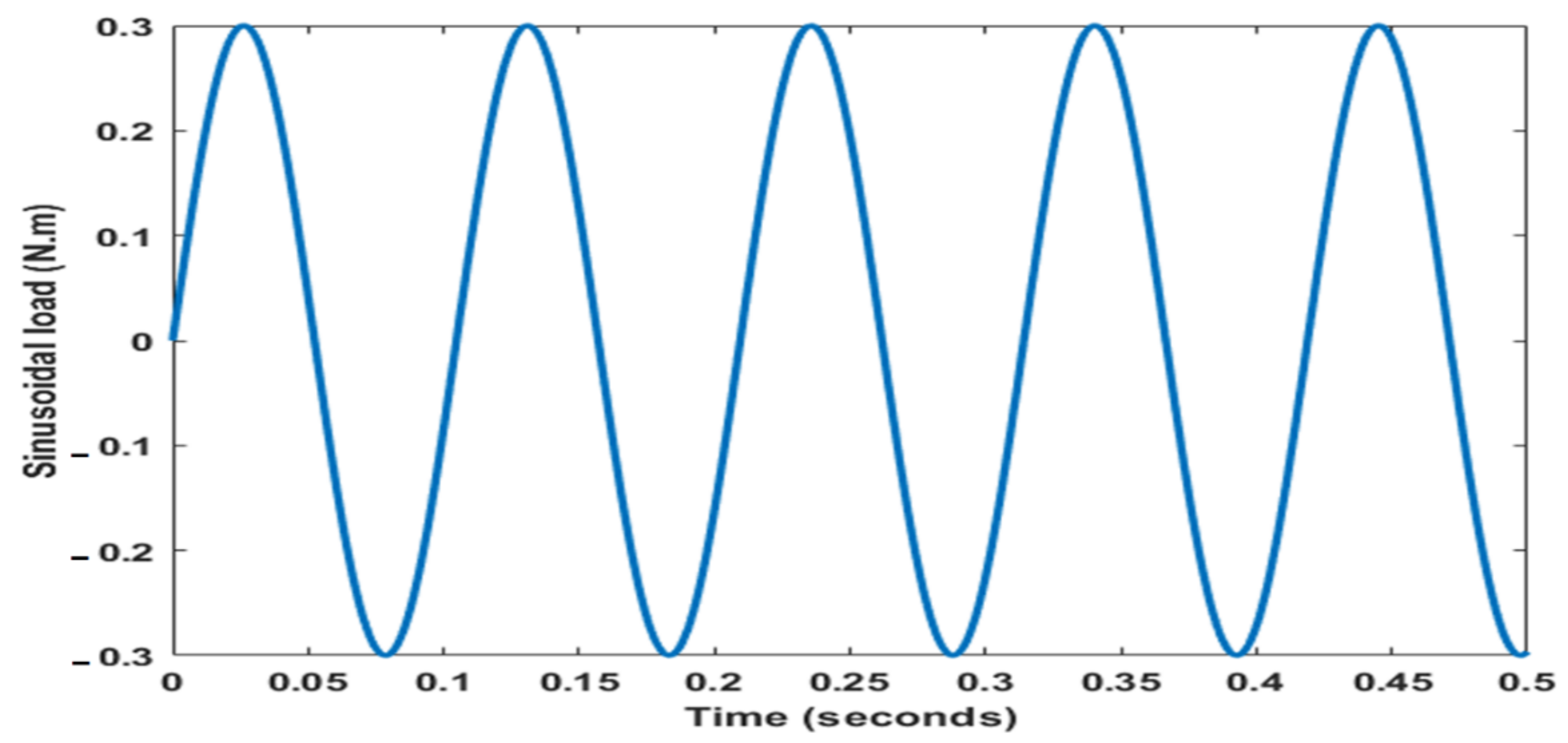
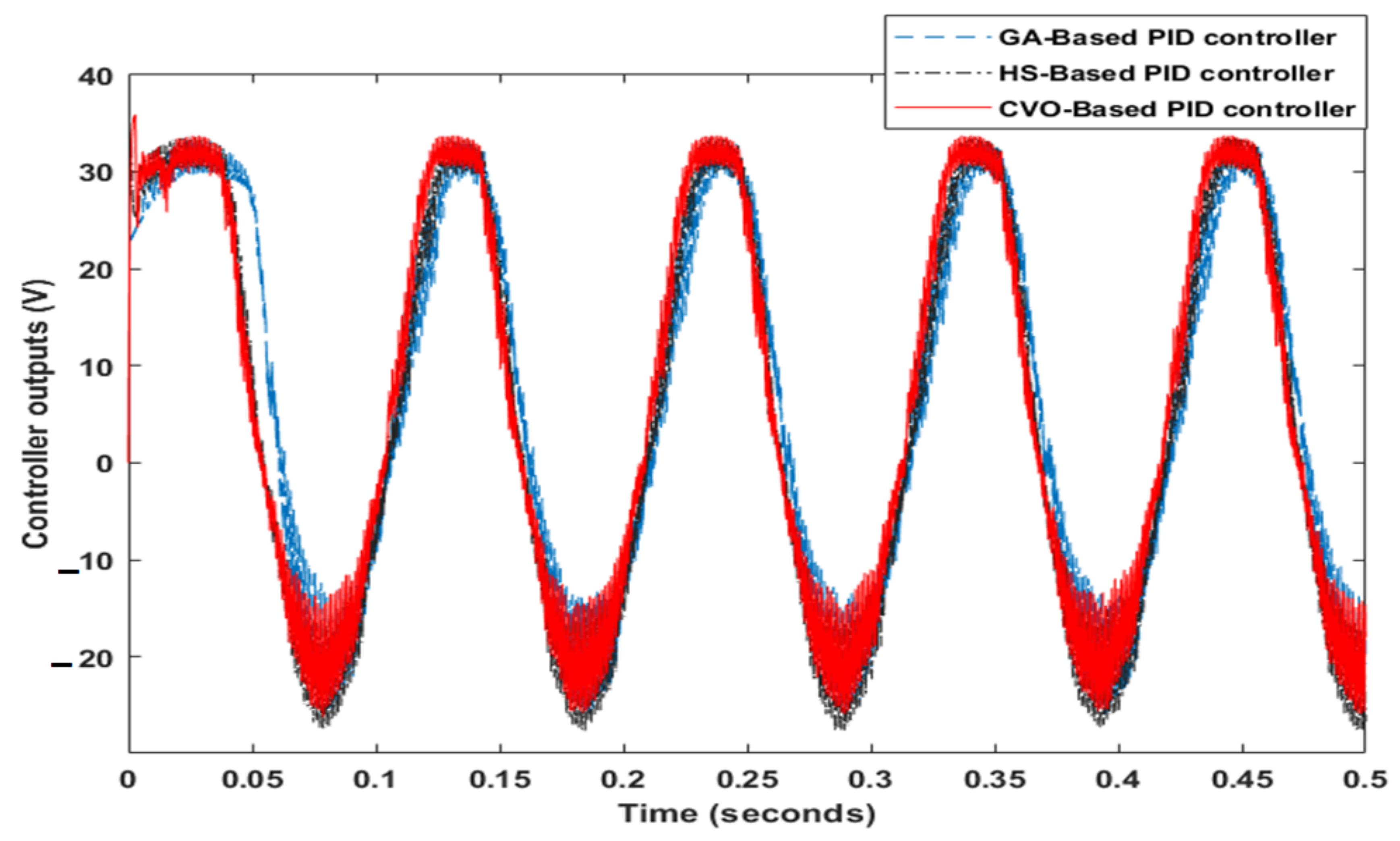
4.2. Speed Regulation at Sinusoidal Load Case

Most of the industrial applications such as robotics and CNC machines are exposed to sinusoidal load because of the rotor movements under continuous change of inertia so need to regulate the speed of the BLDC motor. Applying sinusoidal load on the BLDC motor drive system as shown in Figure 9. Figure 10 displays that the CVOA-based PID controller can track the reference speed better than other techniques (GA-based PID controller and HS-based PID controller) although the sinusoidal load. Where the CVOA-based PID controller has maximum speed tolerance about the reference speed ±4 RPM while the maximum deviation of GA-based PID controller ±25 RPM and the HS-based PID controller is ±10 RPM.
Figure 11 illustrates the corresponding controller output of each control technique at sinusoidal load torque. It can be noted that the controller output is fluctuating to can absorb the sinusoidal load disturbance. The phase shift between the output of the CVOA-based PID controller and the phase of the sinusoidal load is very small so, it can give a high performance through the continuous change of load.

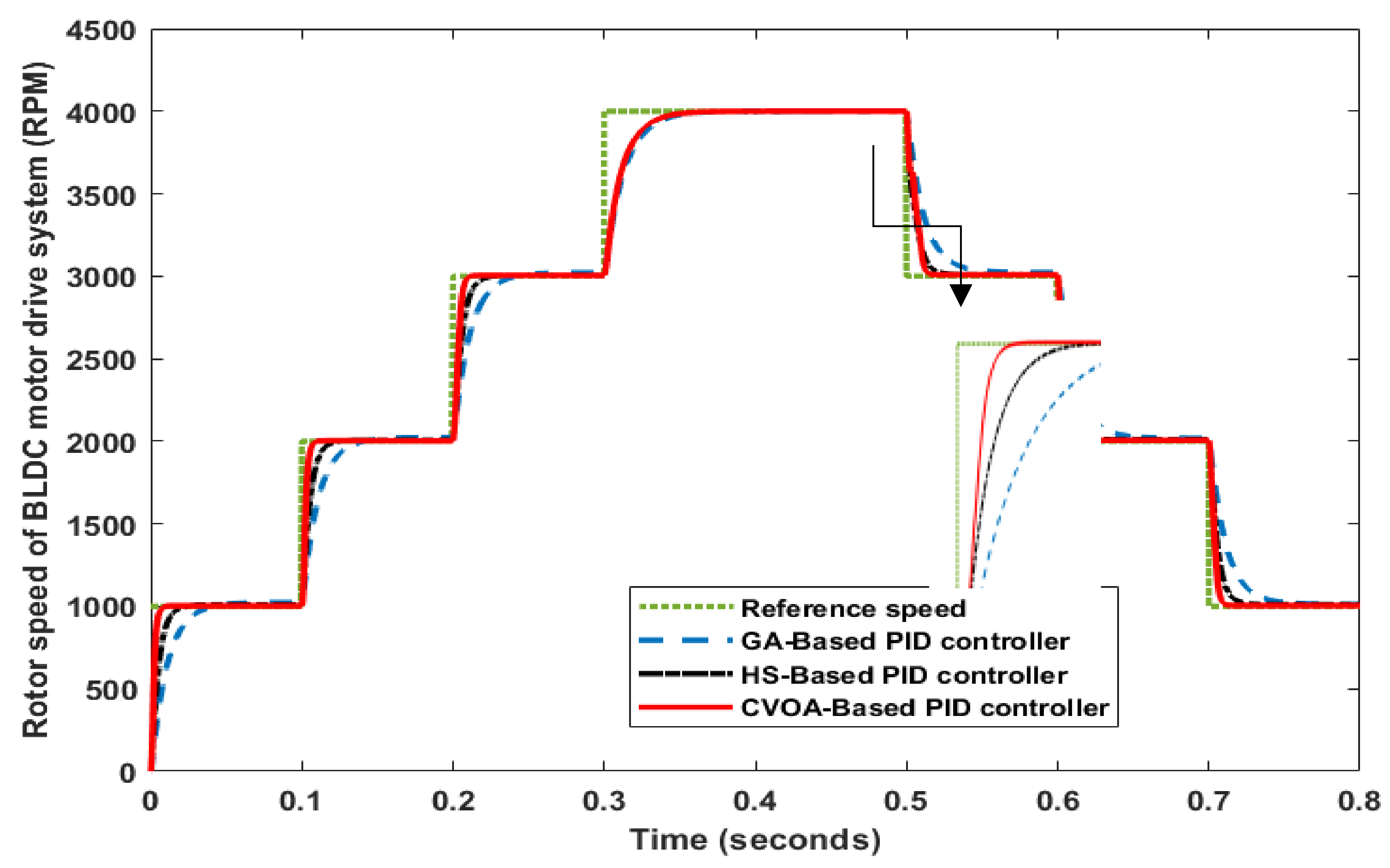
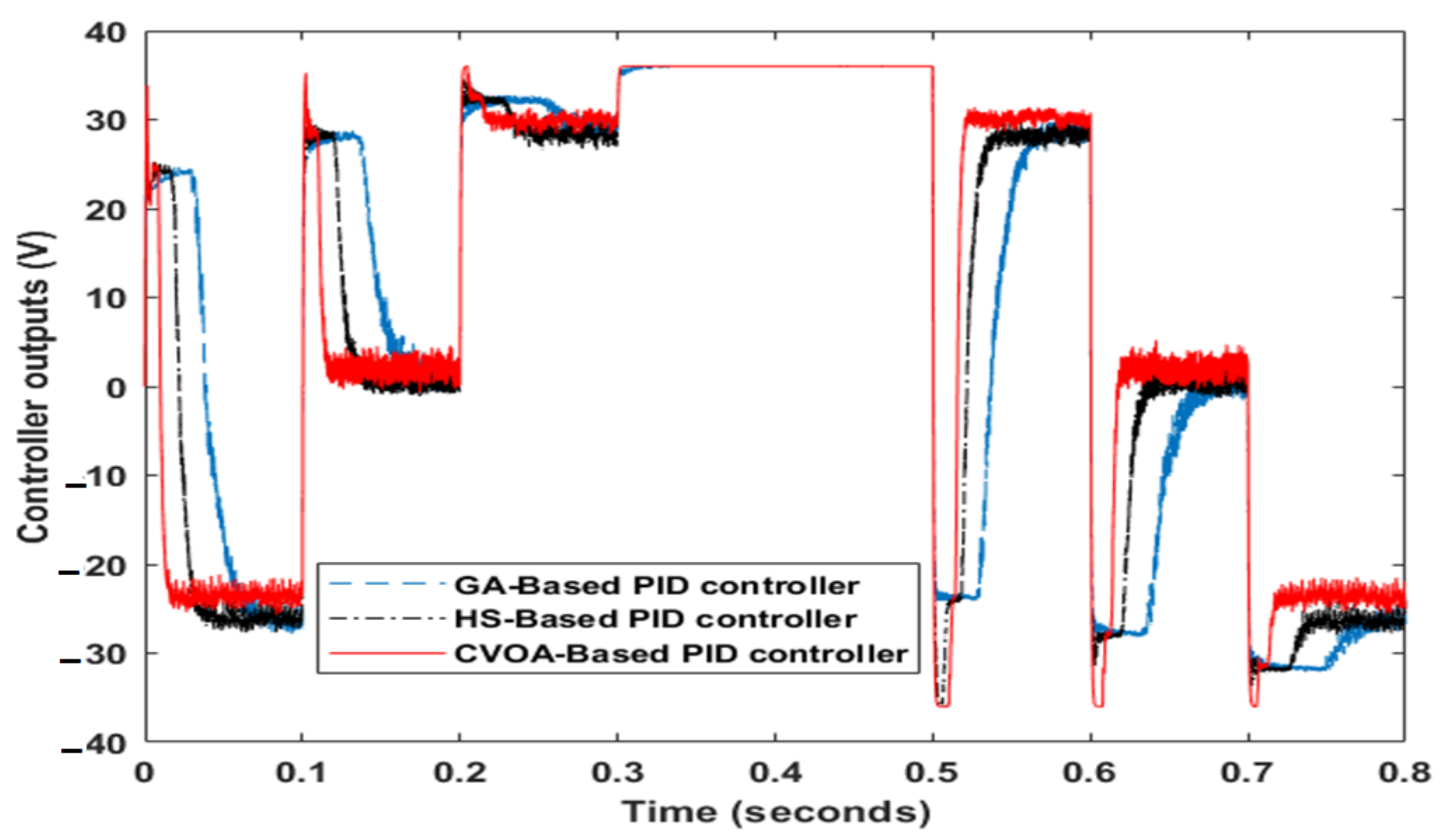
4.3. Speed Tracking Case

Figure 12 displays the dynamic performance of each control technique. It can be noted that the CVOA-based PID controller can follow accurately the reference speed of the BLDC motor. At low reference speeds, the tracking accuracy is high while the error between the reference and actual speed will increase for high reference speeds.
Figure 13 exhibits the controller outputs of each control technique. It can be noted that the response of CVOA-based PID controller output can change rapidly according to the variation of the reference speed. The polarity of controller outputs for the proposed control techniques will be reversed due to the reference speed transit from high value to low value. There is not shuttering at the highest value of reference speed because all controller outputs generate the maximum voltage of the motor. The on-off switching of transistors of the inverter causes a shuttering in signal output for the controller outputs.

5. Conclusions

A new coronavirus optimization algorithm (CVOA) is developed to design an optimal PID controller that can accurately track a preselected reference speed of brushless DC (BLDC) motor under several types of disturbances. The zero patient is presented by the initial values of PID controller parameters, which can infect new patients (the upper and lower values for PID controller parameters). The CVOA model is designed to simulate as accurately as possible the coronavirus behavior. The advantage of CVOA is its parameters can adapt according to disease statistics to prevent the trial and error of designers that occurs when initializing them with arbitrary values. In addition, the algorithm has the ability to end after several iterations when the infected population cannot infect new individuals. The proposed CVOA was compared with well-known optimization techniques such as the genetic algorithm (GA) and Harmony Search (HS) optimization. A multi-objective function can adjust the desired rise time, the desired settling time, the desired overshoot, and the desired steady-state error. Several tests have been executed to study the obtained appropriate values of PID controller parameters. The first test, the BLDC motor is the regulation speed with the sudden load. In the second test, the variable sinusoidal load is subjected to the rotor of the BLDC motor. In the third test, several commands of reference speed are selected to the rotor of the BLDC motor. The results prove that the CVOA-based PID controller can enhance the performance of the BLDC motor drive system where the motor dynamic will be improved (minimum rise time, minimum settling time, and acceptable overshoot).

Funding

This research received no external funding.

Institutional Review Board Statement

Not applicable.

Informed Consent Statement

Not applicable.

Acknowledgments

The author would like to offer thanks to Abdel-Ghany Mohamed and Adel EL Samahy, Faculty of Engineering, Helwan University, for their efforts in designing the BLDC motor model.

Conflicts of Interest

The author declares no conflict of interest.

References

  1. Kumar, S.D. Modeling of brushless dc drive using genetic algorithm based tuning of pid con-troller. IJEEER 2014, 4, 113–126. [Google Scholar]
  2. Chen, S.-C.; Kuo, C.-Y. Design and implementation of double-integral sliding-mode controller for brushless direct current motor speed control. Adv. Mech. Eng. 2017, 9, 1–9. [Google Scholar] [CrossRef] [Green Version]
  3. Kota, R.T.U.K. Tuning of PID Controller for A Linear Brushless DC Motor using Swarm Intelligence Technique Pooja Sharma, Rajeev Gupta. J. Eng. Res. Appl. 2014, 4, 125–128. [Google Scholar]
  4. Navatakke, R.R.; Bichagatti, J. Optimal PID control of a brushless DC motor using PSOtechnique. IOSR J. Electr. Electron. Eng. 2015, 10, 13–17. [Google Scholar] [CrossRef]
  5. Selvakumar, P.; Kannadasan, T. Comparative Study of Intelligent Controllers for Brushless. Dc Motor. J. Theor. Appl. Inf. Technol. 2014, 63, 431–436. [Google Scholar]
  6. Reddy, C.S.R.; Kalavathi, M.S. Performance Analysis of BLDC Motor Drive using New Simulation Model with Fuzzy and ANFIS Speed Controllers. Glob. J. Res. Eng. F Electr. Electron. Eng. 2014, 14, 55697187. [Google Scholar]
  7. Reddy, P.N. Modeling and Analysis of PI Controller Based Speed Control of Brushless DC Motor Drive. IJESRT 2013, 2, 2226–2231. [Google Scholar]
  8. Purwadi, A.; Dozeno, J.; Heryana, N. Testing Performance of 10 kW BLDC Motor and LiFePO4 Battery on ITB-1 Electric Car Prototype. Procedia Technol. 2013, 11, 1074–1082. [Google Scholar] [CrossRef] [Green Version]
  9. Shamseldin, M.; Eissa, M.A.; EL-Samahy, A. Practical Implementation of GA-Based PID Controller for Brushless DC Motor. In Proceedings of the 17th International Middle East Power System Conference (MEPCON’15), Mansoura University, Mansoura, Egypt, 15–17 December 2015. [Google Scholar]
  10. Bingul, Z.; Karahan, O. Comparison of PID and FOPID controllers tuned by PSO and ABC algorithms for unstable and integrating systems with time delay. Optim. Control Appl. Methods 2018, 39, 1431–1450. [Google Scholar] [CrossRef]
  11. Sun, C.; Gong, G.; Wang, F.; Yang, H.; Ouyang, X. Single neuron adaptive PID control for hydro-viscous drive clutch. In Proceedings of the 2016 12th IEEE/ASME International Conference on Mechatronic and Embedded Systems and Applications (MESA), Auckland, New Zealand, 29–31 August 2016; pp. 1–4. [Google Scholar] [CrossRef]
  12. Shamseldin, M.A.; Sallam, M.; Bassiuny, A.M.; Mohamed, A.G. LabVIEW implementation of an enhanced nonlinear PID controller based on harmony search for one-stage servomechanism system. J. Comput. Appl. Res. Mech. Eng. 2020, 10, 111–123. [Google Scholar] [CrossRef]
  13. Shamseldin, M.A.; Sallam, M.; Bassiuny, A.M.; Abdel, A. A new model reference self-tuning fractional order PD control for one stage servomechanism system. WSEAS Trans. Syst. Control 2019, 14, 8–18. [Google Scholar]
  14. Shamseldin, M.A.; Sallam, M.; Bassiuny, A.M.; Ghany, A.M.A. Real-time implementation of an enhanced nonlinear PID controller based on harmony search for one-stage servomechanism system. J. Mech. Eng. Sci. 2018, 12, 4161–4179. [Google Scholar] [CrossRef]
  15. Pillai, B.; Nair, K.T. Intelligent adaptive controller for DC servo motor position control in LabVIEW. In Proceedings of the 2017 International Conference on Intelligent Computing, Instrumentation and Control Technologies (ICICICT), Kannur, India, 6–7 July 2017; pp. 981–985. [Google Scholar] [CrossRef]
  16. Shamseldin, M.; Abdel Ghany, M.; Hendawey, Y. Optimal Nonlinear PID Speed Control Based on Harmony Search for An Electric Vehicle Optimal Nonlinear PID Speed Control Based on Harmony Search for An Electric. Future Eng. J. 2021, 2, 4. [Google Scholar]
  17. Wang, C.; Quan, L.; Jiao, Z.; Zhang, S. Nonlinear Adaptive Control of Hydraulic System With Observing and Compensating Mismatching Uncertainties. IEEE Trans. Control Syst. Technol. 2017, 26, 927–938. [Google Scholar] [CrossRef]
  18. Dinc, A.; Otkur, M. Optimization of Electric Vehicle Battery Size and Reduction Ratio Using Genetic Algorithm. In Proceedings of the 2020 11th International Conference on Mechanical and Aerospace Engineering (ICMAE), Athens, Greece, 14–17 July 2020; Institute of Electrical and Electronics Engineers (IEEE): New York, NY, USA, 2020; pp. 281–285. [Google Scholar]
  19. Alanazi, S.A.; Kamruzzaman, M.M.; Alruwaili, M.; Alshammari, N.; Alqahtani, S.A.; Karime, A. Measuring and Preventing COVID-19 Using the SIR Model and Machine Learning in Smart Health Care. J. Healthc. Eng. 2020, 2020, 1–12. [Google Scholar] [CrossRef]
  20. Kozioł, K.; Stanisławski, R.; Bialic, G. Fractional-Order SIR Epidemic Model for Transmission Prediction of COVID-19 Disease. Appl. Sci. 2020, 10, 8316. [Google Scholar] [CrossRef]
  21. Águila-León, J.; Chiñas-Palacios, C.D.; Vargas-Salgado, C.; Hurtado-Perez, E.; García, E.X. Optimal PID Pa-rameters Tunning for a DC-DC Boost Converter. In Proceedings of the 2020 IEEE Conference on Technologies for Sustainability (SusTech) Optimal, Las Vegas, NV, USA, 24–25 April 2020; pp. 40–45. [Google Scholar]
  22. Kumar, M.; Chaursiya, K. Position control of brushless DC motor using harmony search algorithm optimization technique. In Proceedings of the 2017 International conference of Electronics, Communication and Aerospace Technology (ICECA), Coimbatore, India, 20–22 April 2017; Volume 1, pp. 754–757. [Google Scholar]
  23. Mukhtar, A.; Tayal, V.K.; Singh, H. PSO Optimized PID Controller Design for the Process Liquid Level Control. In Proceedings of the 2019 3rd International Conference on Recent Developments in Control, Automation & Power Engineering (RDCAPE), Noida, India, 10–11 October 2019; pp. 590–593. [Google Scholar] [CrossRef]
  24. Bennaoui, A.; Saadi, S.; Ameur, A. Performance Comparison of MFO and PSO for Optimal Tuning the fractional order fuzzy PID Controller for A DC-DC Boost Converter. In Proceedings of the 2020 International Conference on Electrical Engineering (ICEE), Istanbul, Turkey, 25–27 September 2020; pp. 1–5. [Google Scholar] [CrossRef]
  25. Yang, L.; Zhu, Z.Q.; Shuang, B.; Bin, H. Adaptive Threshold Correction Strategy for Sensorless High-Speed Brushless DC Drives Considering Zero-Crossing-Point Deviation. IEEE Trans. Ind. Electron. 2019, 67, 5246–5257. [Google Scholar] [CrossRef]
  26. Maharajan, M.P.; Xavier, S.A.E. Design of Speed Control and Reduction of Torque Ripple Factor in BLdc Motor Using Spider Based Controller. IEEE Trans. Power Electron. 2019, 34, 7826–7837. [Google Scholar] [CrossRef]
  27. Gaurav, A.; Gaur, A. Modelling of Hybrid Electric Vehicle Charger and Study the Simulation Results. In Proceedings of the 2020 International Conference on Emerging Frontiers in Electrical and Electronic Technologies (ICEFEET), Aarhus, Denmark, 10–11 July 2020; Institute of Electrical and Electronics Engineers (IEEE): New York, NY, USA, 2020; pp. 1–6. [Google Scholar]
  28. Shamseldin, M.A.; El-Samahy, A.A.; Ghany, A. Different techniques of self-tuning FOPID control for Brushless DC Motor. In Proceedings of the 2016 Eighteenth International Middle East Power Systems Conference (MEPCON), Cairo, Egypt, 27–29 December 2016; pp. 342–347. [Google Scholar]
  29. Nasri, M.; Nezamabadi-Pour, H.; Maghfoori, M. A PSO-Based Optimum Design of PID Controller for a Linear Brushless DC Motor. Int. J. Electr. Robot. Electron. Commun. Eng. 2007, 1, 184–188. [Google Scholar]
  30. Deraz, S.A. Genetic Tuned PID Controller Based Speed Control of DC Motor Drive. Int. J. Eng. Trends Technol. 2014, 17, 88–93. [Google Scholar] [CrossRef] [Green Version]
  31. Omar, M.; Soliman, M.; Ghany, A.M.A.; Bendary, F. Optimal Tuning of PID Controllers for Hydrothermal Load Frequency Control Using Ant Colony Optimization. Int. J. Electr. Eng. Inform. 2013, 5, 348–360. [Google Scholar] [CrossRef]
  32. Kiran, S.R.; Amani, G. Load Frequency Control of a Two-Area Power System Using FOPID with Harmony Search Algorithm. Natl. Conf. Trends Eng. Technol. 2017, 6495, 12–17. [Google Scholar] [CrossRef]
  33. Omar, M.; Ebrahim, M.A.; Abdel Ghany, A.M.; Bendary, F. Reduced Size Harmony Search Algorithm for Optimization. J. Electr. Eng. 2016, 1, 1–8. [Google Scholar]
  34. Omar, M.; Ebrahim, M.A.; Ghany, A.M.A.; Bendary, F. Tuning of PID Controller for Load Frequency Control Problem via Harmony Search Algorithm. Indones. J. Electr. Eng. Comput. Sci. 2016, 1, 255–263. [Google Scholar] [CrossRef]
  35. Banu, U.S.; Lakshmanaprabu, S.K. Multivariable Centralized Fractional Order PID Controller tuned using Harmony search Algorithm for Two Interacting Conical Tank Process. In Proceedings of the SAI Intelligent Systems Conference, London, UK, 10–11 November 2015; pp. 320–327. [Google Scholar]
  36. Omar, M.; Ghany, A.M.A.; Bendary, F. Harmony Search based PID for Multi Area Load Frequency Control Including Boiler Dynamics and Nonlinearities. WSEAS Trans. Circuits Syst. 2015, 14, 407–414. [Google Scholar]
  37. Martínez-Álvarez, F.; Asencio-Cortés, G.; Torres, J.F.; Gutiérrez-Avilés, D.; Melgar-García, L.; Pérez-Chacón, R.; Rubio-Escudero, C.; Riquelme, J.C.; Troncoso, A. Coronavirus Optimization Algorithm: A Bioinspired Metaheuristic Based on the COVID-19 Propagation Model. Big Data 2020, 8, 308–322. [Google Scholar] [CrossRef]
Figure 1. BLDC Motor Block Diagram.
Algorithms 14 00193 g001
Figure 2. Open-loop response of BLDC motor drive system model.
Algorithms 14 00193 g002
Figure 3. The corresponding phase current of the BLDC motor model.
Algorithms 14 00193 g003
Figure 4. The CVOA tuning system with BLDC motor drive system.
Algorithms 14 00193 g004
Figure 5. The convergence curve for GA, HS, and CVOA.
Algorithms 14 00193 g005
Figure 6. The CVOA flow chart.
Algorithms 14 00193 g006
Figure 7. The speed of BLDC motor at speed regulation with sudden load test.
Algorithms 14 00193 g007
Figure 8. The controller outputs at speed regulation with sudden load test.
Algorithms 14 00193 g008
Figure 9. The applied sinusoidal load.
Algorithms 14 00193 g009
Figure 10. The speed regulation at the sinusoidal load test.
Algorithms 14 00193 g010
Figure 11. The controller outputs at the sinusoidal load test.
Algorithms 14 00193 g011
Figure 12. The rotor speed of the BLDC motor at several operating points of the reference speed test.
Algorithms 14 00193 g012
Figure 13. The controller outputs at several operating points of reference speed.
Algorithms 14 00193 g013
Table 1. The BLDC motor parameters.
RatingSymbolValueUnits
DC resistanceR0.57
InductanceL1.5mH
Torque constantKT0.082N.m/A
No. of PolesP4
Rated torqueTp0.42N.m
Rated VoltageV36V
Rotor InertiaJ23 × 10−6Kg.m2
Friction coefficientBv0.0000735N.M. S
Rated Speedω4000RPM
Rated currentI5A
Table 2. The CVOA parameters.
No.CVOA ParameterSymbolValue
1Probability of DeathPDIErandom value from 0 to 1
2Death RateDRrandom value from 0 to 1
3Spreading RateSRrandom value from 0 to 0.5
4Super Spreading RateSRRrandom value from 0.5 to 1
5Probability of travelPtrandom binary value 0 or 1
6Lower boundary LX[0.1, 0.1, 0.1]
7Upper boundaryUX[100, 100, 10]
Table 3. The obtained parameters of each control technique.
Control TechniqueKpKiKd
GA-based PID controller40.32550.230.401
HS-based PID controller90.56466.3650.352
CVOA-based PID controller85.14470.3650.121
Table 4. The performance of each control technique.
Control TechniqueRise Time (s)Settling Time (s) Overshoot (%)
GA-based PID controller0.02340.04170.0089
HS-based PID controller0.01040.01910.0159
CVOA-based PID controller0.00420.00790.0511
Publisher’s Note: MDPI stays neutral with regard to jurisdictional claims in published maps and institutional affiliations.

