1. Introduction
Recently, data traffic is increasing explosively as a variety of user equipment (UE) and intelligent devices such as smartphones, tablets, smart cars, and smart home devices go hand in hand with the evolution of cloud computing and network softwarization technologies. With the increase in the network diversity and complexity to manage multiple devices and to optimize the distribution and delivery of increasing amounts of data traffic, the efficient operation and management of network service resources becomes complicated. In order to overcome this problem, as a way of applying automation and intelligence to network infrastructure, the software-defined network (SDN) is evolving for dynamic and virtualized networking services, efficient network management, and cost-saving benefits in network deployment and operations [
1,
2].
The SDN can manage and control network resources using a logically centralized controller that is separated from the data transmission layer called the data plane. For example, OpenFlow is an SDN technology to abstract and control the flow table in OpenFlow-enabled switches, adjusting data delivery paths on the basis of flow information [
3]. An SDN controller acts like a network operating system (NOS). It monitors and collects network status and configuration data in real time to evaluate the global network topology while making network devices dynamically programmable. In this procedure, network automation and intelligence can be provided with an SDN, and one of the latest technological trends of SDNs is to pursue network resource virtualization and dynamic network slicing for automated and intelligent network management integrated with machine learning and deep learning technologies [
4,
5]. By applying network automation and intelligence to network infrastructure, the collected network big data (e.g., logs, flows, events, and status) are analyzed by machine learning and deep learning models, and exploited for configuration, management, control, and orchestration of physical and virtual network resources.
As a use case in the network virtualization and orchestration, KREONET-S (Korea Research Environment Open Network Softwarization) was developed to operate as a wide-area SDN infrastructure spanning five regions in South Korea, two regions in the United States, and one region in China, adopting OpenFlow as its southbound interface [
6,
7]. Virtual dedicated network (VDN) and VDN orchestrator (VDNO) applications are being developed and deployed over KREONET-S to provide end-to-end virtual network slicing and automated orchestration capability for UE, end-hosts, and cloud resources, gaining high quality of data transmission and secure end-to-end communication services enabled by dynamic and dedicated resource (e.g., network bandwidth) provisioning.
In addition, considering cloud computing as another evolutionary information and communications technology (ICT) shift, multi-access edge computing (MEC) has become an essential technology for collecting, analyzing, and processing data generated by widely distributed user equipment (UE), wireless end-hosts, Internet of things (IoT) sensors, etc., providing real-time and high-quality networking services with ultralow end-to-end latency guaranteed between various user devices and edge cloud computing nodes. The European Telecommunication Standard Institute (ETSI) MEC ISG [
8,
9,
10] is primarily involved in the standardization efforts of MEC which is considered a key component of future fifth- and sixth-generation (5G and 6G) systems to meet the requirements of telecommunication operators in terms of flexibility and reconfigurability for the increasing traffic demand [
11,
12]. MEC brings processing and storage capabilities to the edge of the network to inspire the development of new IoT applications and services through intelligent and big data analytics [
13], and to offload the applications demanding huge processing resources from mobile devices to the edge computing cloud [
14]. MEC can improve latency and bandwidth utilization while making users, developers, and content providers access network services more easily on the basis of its realization technologies including SDN and network slicing [
15,
16,
17].
However, there is an arising issue that the cloud resources at the MEC on-site (access point) and edge site are restricted and insufficient primarily because of the operation and management constraints (e.g., limited space and capacity) in the case of on-demand dynamic computing and storage resource deployment in cloud-assisted mobile and multi-access edge computing by end-user requests in particular [
18,
19,
20]. Resource provisioning in the MEC environment generally embraces hypervisor-based and container-based virtualization technologies. Furthermore, as the edge or distributed cloud is increasingly prevailing, it is desired that lightweight and container-based service resources are converged with an automated and intelligent networking environment. Therefore, a resource integration and orchestration technology is required to select and allocate computing, storage, and network resources efficiently over the SDNized and containerized edge cloud infrastructure in order for dynamic resource management; thus, MEC services can be enhanced with the improved quality of experience and service in a more intelligent and secure way.
In this paper, we propose a dynamic and flexible network virtualization and orchestration scheme for automated and selective MEC services over a wide-area SDN (KREONET-S).
Section 2 introduces how KREONET-S operates as a wide-area SDN infrastructure that meets the MEC-specific dynamic resource provisioning requirements.
Section 3 describes the development of VDN and VDNO applications that can be utilized for selective MEC services by using a location- and load-aware approach. Consequently, as a use case of network automation based on dynamic virtual network slicing over KREONET-S, an experiment using Globus Online [
21] is explained in association with the virtual networking (VDN) and orchestration (VDNO) technologies in
Section 4. Finally, we conclude this article in
Section 6 after considering a multitier service architecture and selective MEC model for the scheme proposed in
Section 5.
2. KREONET-S: Wide-Area SDN Infrastructure Development and Deployment
SDN has attracted much attention as a new network paradigm. Open Network Foundation (ONF) [
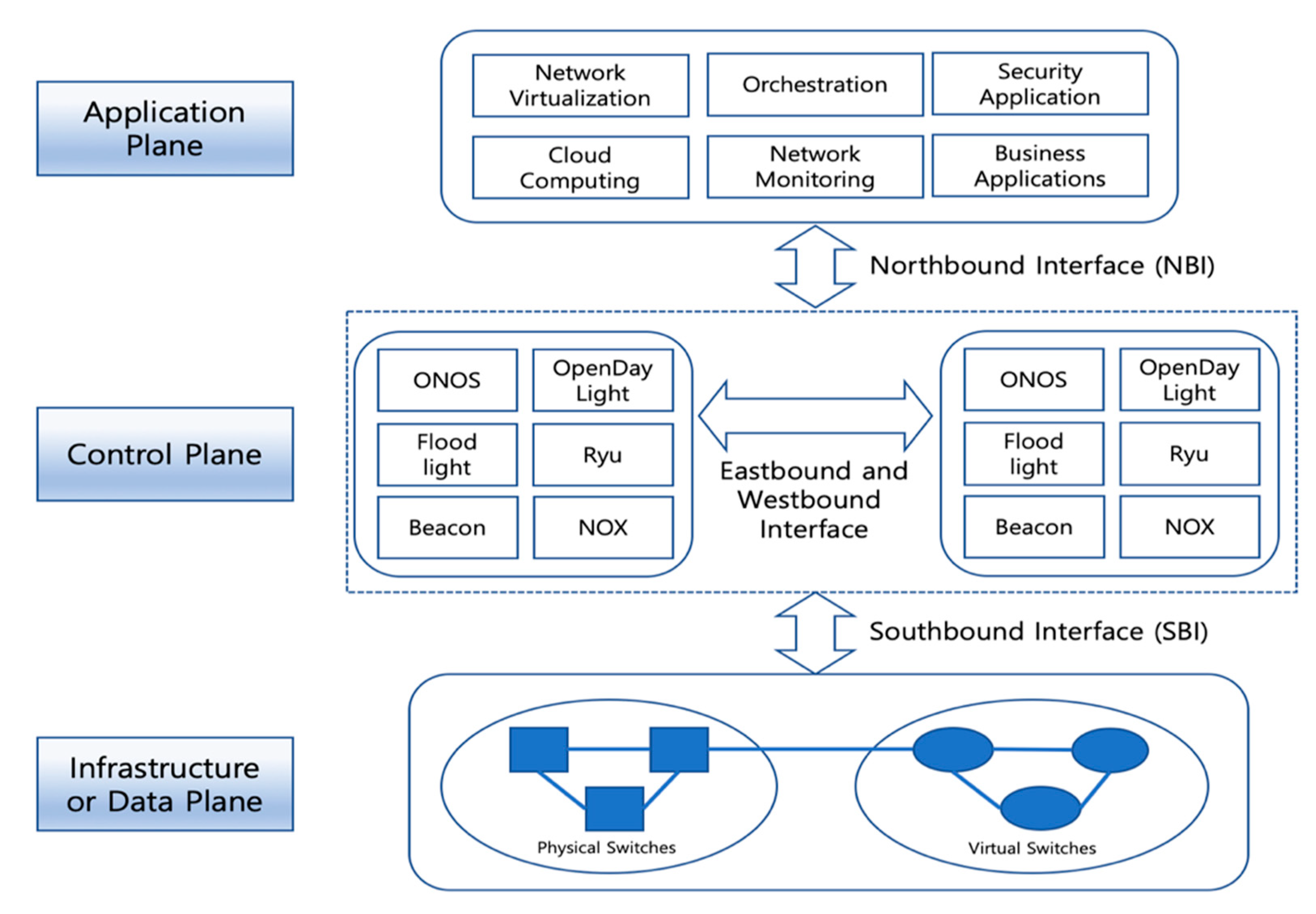
22] is a founder of SDN and leads the technology development, interface and data model standardization, and SDN commercialization in a joint effort and partnership with major telecommunications and service providers in the world. According to ONF, SDN is defined as follows: “the data plane and control plane are separated in SDN architecture, and network intelligence and network status information are logically centralized in the control plane. Network infrastructure is abstracted from the perspective of applications.” The SDN architecture is composed of a data plane, a control plane, and an application plane, which are associated with the southbound interface (SBI) and northbound interface (NBI) on the basis of the aforementioned definition by ONF.
Figure 1 shows that the SBI interconnects the data plane and the control plane, and the NBI provides abstracted network information by interconnecting the control plane and the application plane. Moreover, multiple SDN controller instances in the control plane can be clustered as a logically centralized controller by exchanging the network topology view and the state information via eastbound and westbound interfaces (EWBIs). The logically centralized controller is capable of high availability and scalability in regard to reliable SDN operations and management, resulting in efficient handling of massive network traffic generated from large-scale and wide-area SDN environments.
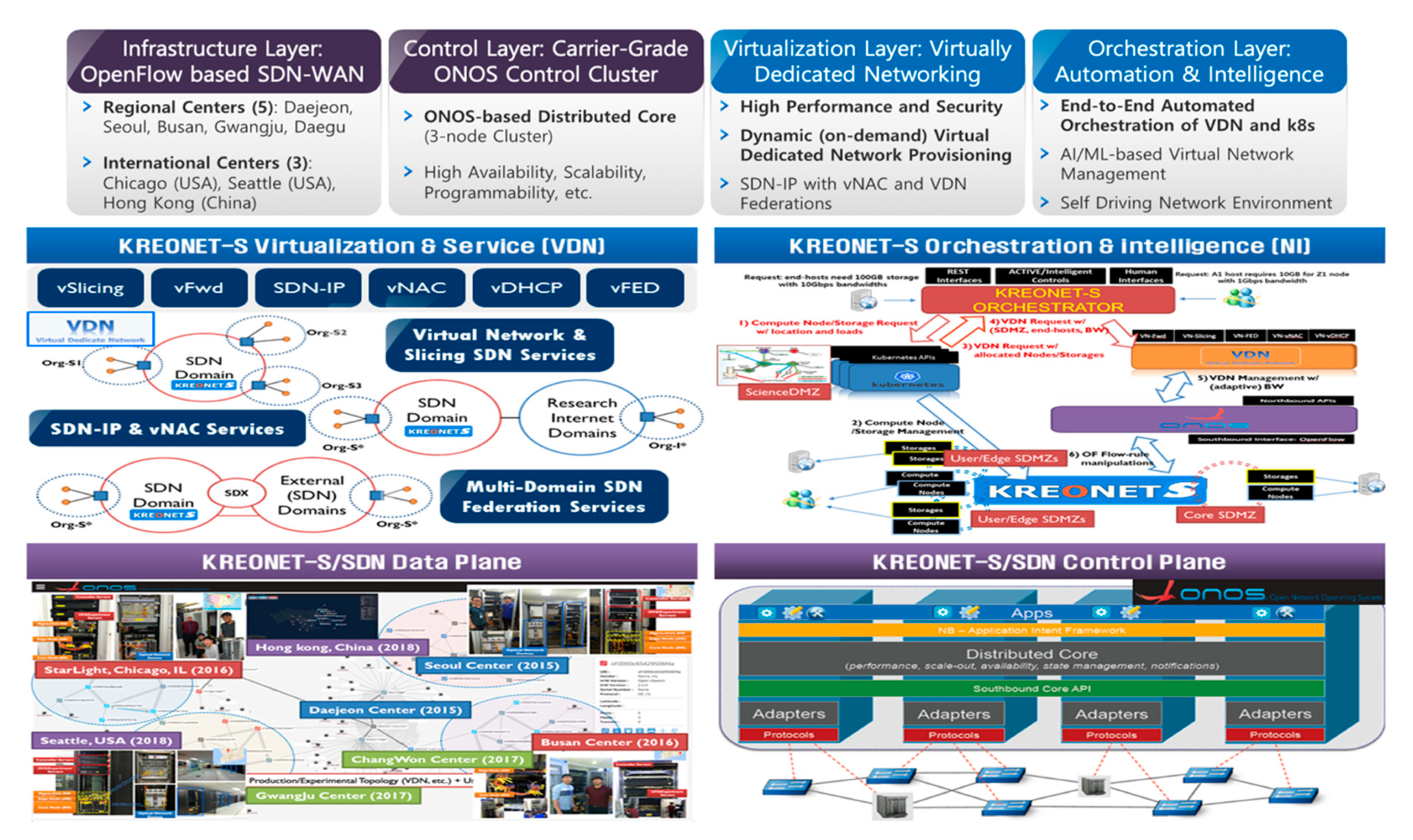
According to the fundamental SDN architecture defined by ONF, as shown in
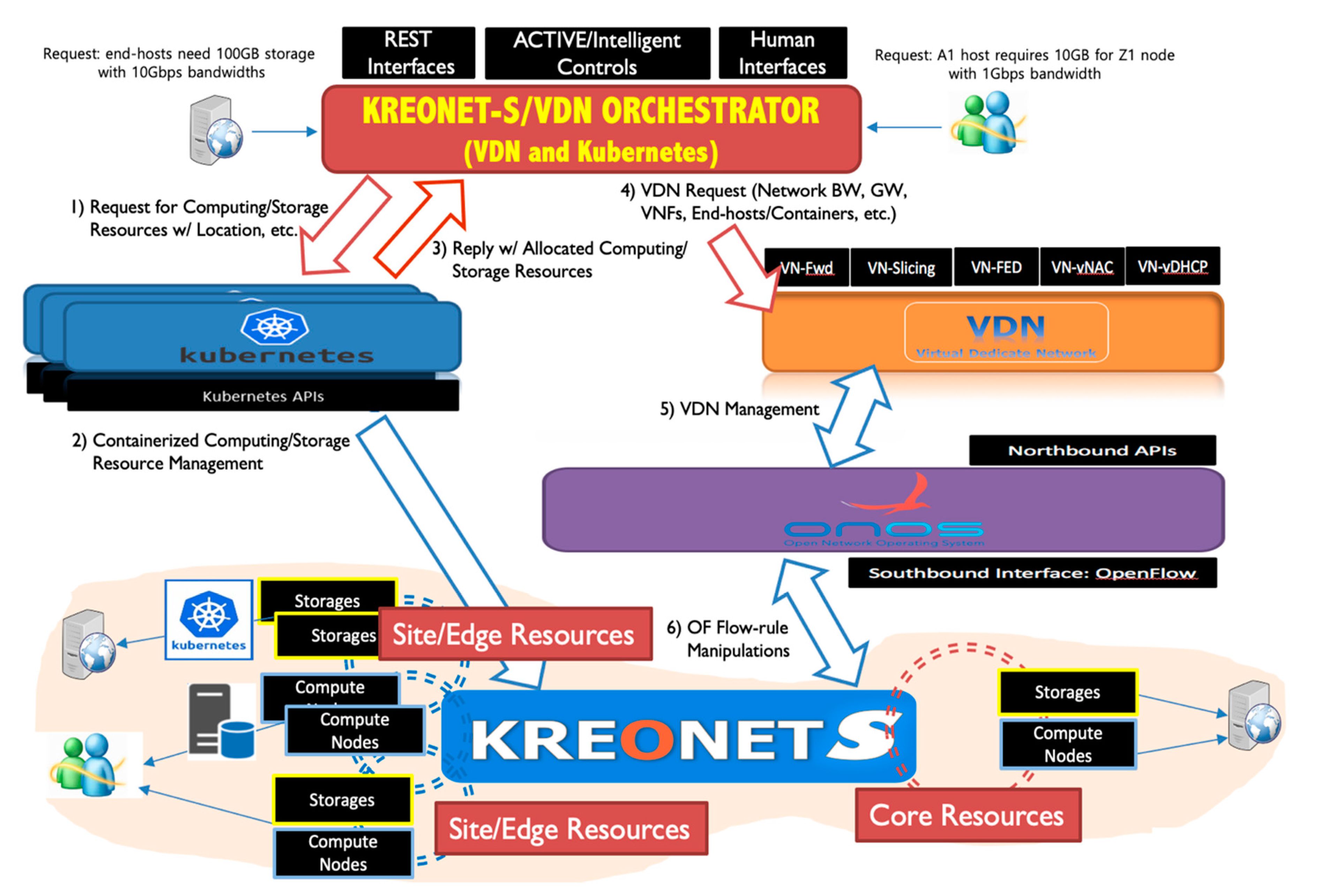
Figure 1, four principal layers are designed and developed for the KREONET-S initiative, namely, the infrastructure layer corresponding to the data plane, the control layer corresponding to the control plane, the virtualization layer corresponding to the application plane, and an additional orchestration layer (for network automation and intelligence) also corresponding to the application plane. KREONET-S has several unique features, as compared with other SDN platforms. First of all, KREONET-S provides a native and tunnel-free wide-area SDN infrastructure, adopting the standard OpenFlow protocol as its southbound interface and APIs. Other SD-WAN technologies developed by the commercial vendors generally use overlay and tunneling mechanisms with the proprietary interfaces and APIs applied, which may cause vendor lock-in issues, thereby hindering heterogeneous and multi-vendor network deployment and further technology development. Furthermore, KREONET-S is differentiated from other platforms and applications that use ONOS as their SDN controller, mainly considering the VDN (and VDNO) capabilities. The VDN system is a district ONOS-oriented application providing logically isolated and dedicated networks over WAN with high performance and strict end-to-end network security guaranteed, particularly using dynamic flow control and automated end-host/UE awareness. On the other hand, other well-known ONOS virtual network applications are rather focused on the datacenter (overlay) network virtualization or LAN virtualization, for example, SONA (Simplified Overlay Networking Architecture) and VPLS (Virtual Private LAN Service). In addition, the VDNO system coordinates the VDN system and Kubernetes to integrate virtual networking, computing, and storage resources in an automated manner, which is described in detail in
Section 3.
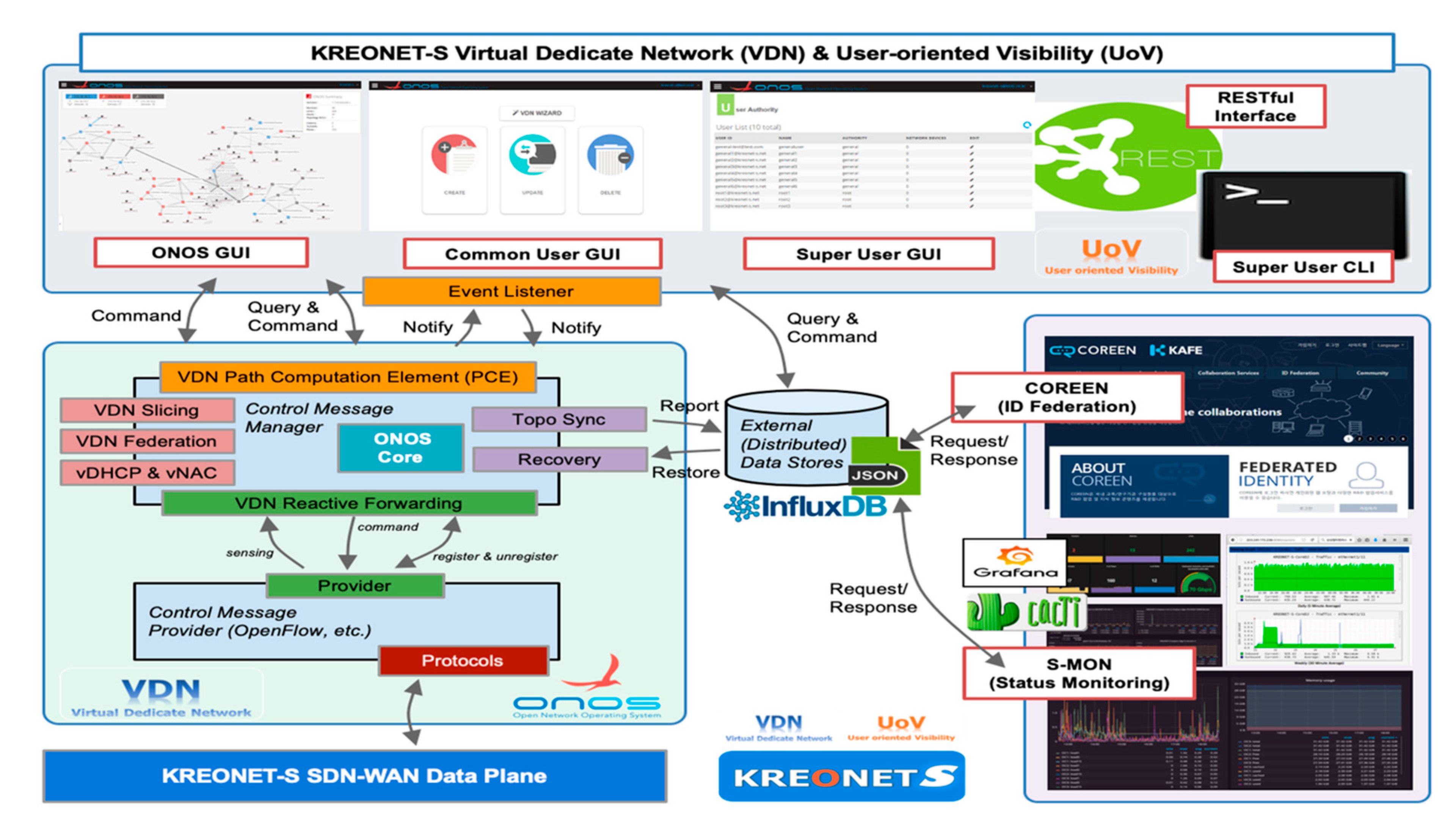
The layered architecture of KREONET-S is indicated in
Figure 2. The infrastructure layer of KREONET-S facilitates OpenFlow-capable core and edge network devices to build a wide-area SDN as a data plane network in five regions in Korea (Daejeon, Seoul, Busan, Gwangju, and Changwon) two regions in the US (Chicago and Seattle), and one region in China (Hong Kong). As a control plane for KREONET-S, an open-source SDN control platform, Open Network Operating System (ONOS) [
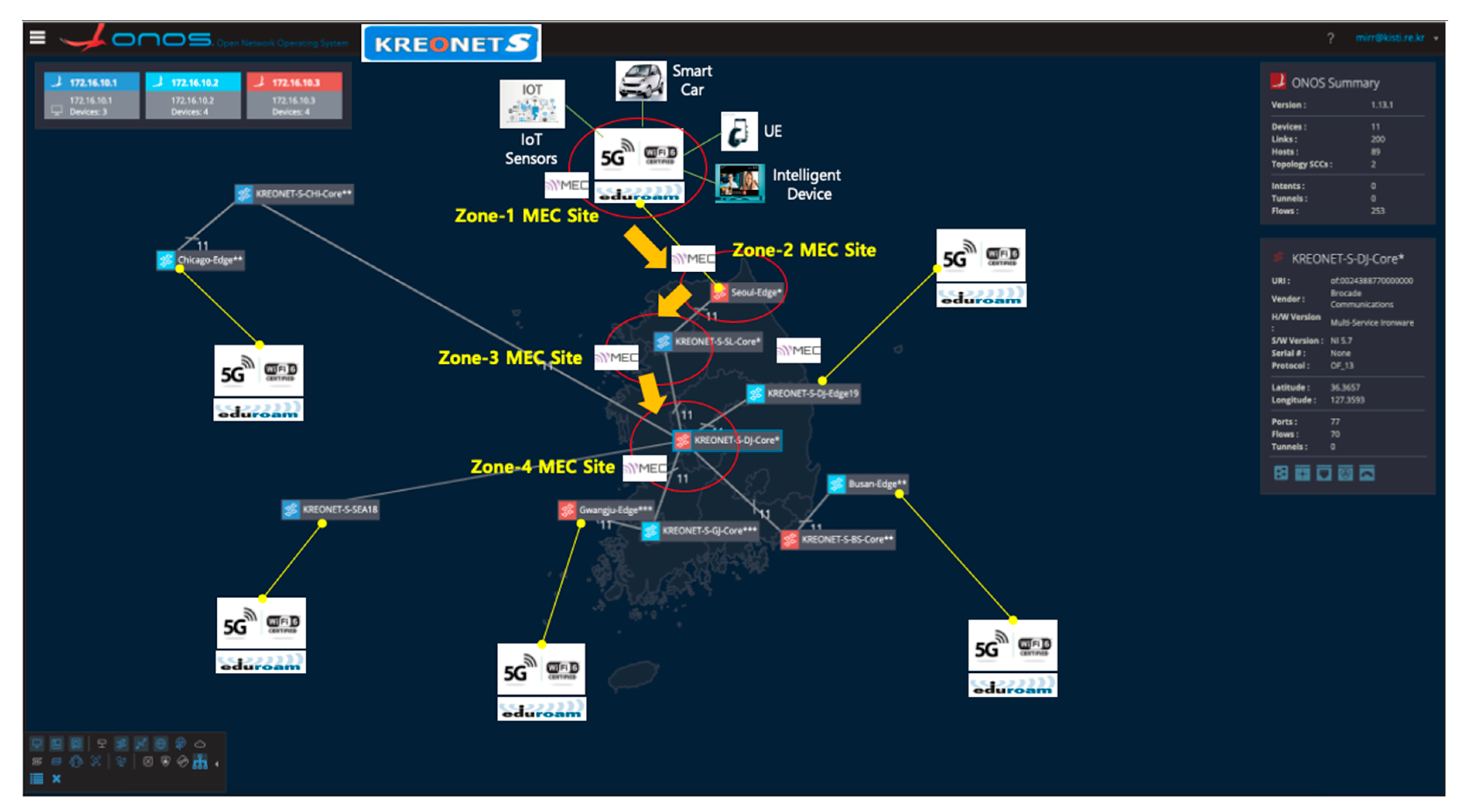
24] developed by ONF is deployed on top of the infrastructure layer with several key application modules newly developed (e.g., reactive forwarding module, topology synchronization module, configuration and recovery module) in order to improve the overall operational stability in the control layer of KREONET-S. The core architecture of ONOS enables individual controller instances to be clustered as one logically centralized controller using eventual and strong consistency in distributed datastores, providing high availability, scalability, and centralized management. The distributed datastores synchronize the states of each controller instance on the basis of appropriate state distribution and consensus mechanisms such as the Atomix framework, Raft algorithm, and gossip protocol. By adopting the ONOS distributed core architecture, KREONET-S operates a three-node ONOS cluster utilizing OpenFlow as the SBI to collect network status and topology information from the widely dispersed network devices in eight locations, and accordingly creates a global network topology as indicated in
Figure 3. The network topology, status, and event information is abstracted by ONOS and delivered to the virtualization layer (also known as the VDN) of KREONET-S through the NBI so that the VDN can provide and manage virtual network slices on the basis of the abstracted global network topology and state information.
VDN basically allocates dedicated network slices so that UEs and intelligent wireless/wired devices can access MEC nodes with optimized latency and bandwidth on the basis of its dynamic and on-demand network resource provisioning capability. Isolating the network slices using SDN in this paper is achieved by the flow isolation mechanism on the basis of the OpenFlow protocol, which is combined with the technologies of data delivery path calculation, VDN reactive forwarding (vFwd), virtual dynamic host configuration protocol (vDHCP), virtual network access control (vNAC), and VDN federation (vFED), as shown in
Figure 2. Each generated slice is labeled with a specific VDN identifier, and then strictly isolated and separated from the other slices on the basis of a segregated flow-rule installation to the corresponding network devices so that end-hosts and UEs in the same slice can only communicate with each other. The VDN mechanism is described in detail in
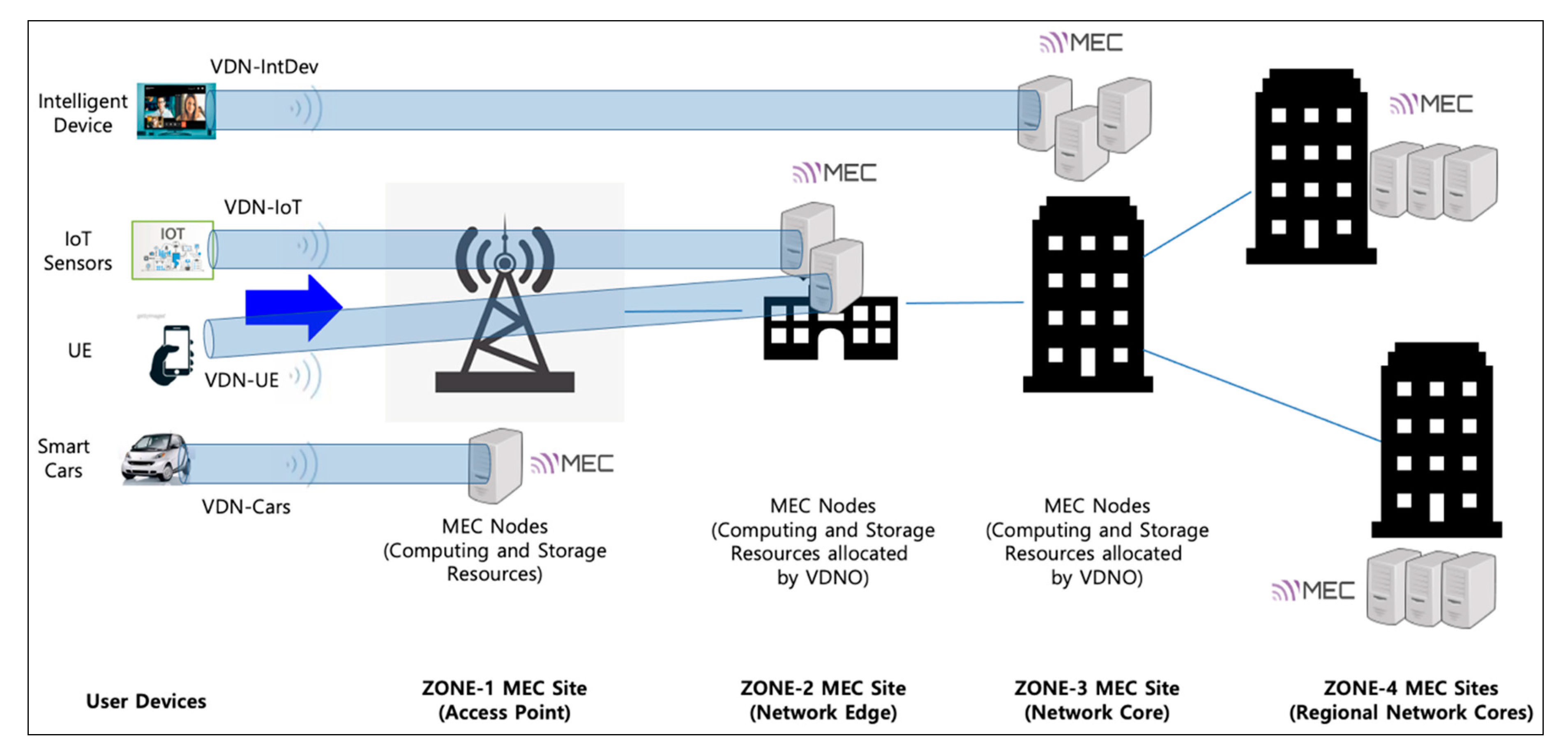
Section 3. Moreover, when computing and storage resources become insufficient by rapidly increasing the number of user devices (e.g., smartphones and smart cars), VDN can provide (location-aware) proximity services for the latency-sensitive and computation-intensive user devices by calculating the shortest path that secures the required bandwidth from user devices to a selective MEC site in the nearest on-site access point or edge network. For example, considering a real-time adaptive video streaming service, a number of dynamically increasing user devices need to receive the stream seamlessly from the first-zone MEC site (on-site access point) or the nearest next-zone MEC site on the basis of the selective MEC service model. For this type of service scenario, we consider the hierarchical and multiple-zone MEC service architecture depicted in
Figure 3, and the architecture is integrated with the underlying KREONET-S global network topology, as shown in
Figure 4.
The hierarchical MEC architecture was introduced in several studies such as radio-aware video optimization in a fully virtualized network (RAVEN) experiment activity [
25] and hierarchical MEC server deployment research [
26], where RAVEN embraces an SD-RAN (Software Defined Radio Access Network) controller to facilitate communication between the controller and the agent residing on network devices, and the latter proposes an integer nonlinear programming model to minimize the resource deployment cost and average latency. Similarly, the MEC service architecture of KREONET-S incorporates a hierarchical model. However, the proposed architecture distinctly applies VDN and VDNO in its own mechanism for network resource utilization and end-to-end latency optimization. The detailed framework and procedure of VDN is described in
Section 3. Likewise, the location- and load-aware VDN orchestration architecture is introduced in the same section to indicate automated and intelligent orchestration, allowing the coordination of virtual network slices and computing and storage resources on demand in an integrated manner.
4. An Automated Virtual Network Slicing Experiment Using Globus Online
This section describes a network automation use case that can be applied to dynamic MEC resource allocation services in terms of cognitive virtual network slice creation and management. The use case in this section takes advantage of Globus Online, which is a grid-oriented, end-to-end, and disk-to-disk large file transfer system, and the VDNO system that coordinates VDN and Kubernetes for containerized resource allocation combined with a dedicated virtual network slice. In order to utilize Globus Online, data transfer nodes (DTNs) are allocated by VDNO in the first place. Globus Online manages each end-system resource to be registered as a DTN endpoint to store a large volume of data and transfer the massive file to another DTN endpoint.
VDNO can generate and manage DTNs dynamically as containerized resources connected to the KREONET-S infrastructure, which enables the DTNs to be included in the specific virtual network slices on demand. If a containerized DTN is registered at Globus Online, it becomes a DTN endpoint which transfers large-scale data to another endpoint using a high-performance file transmission application such as GridFTP on the basis of its simplified user interface. Globus Online basically offers Open APIs for authorization (Auth) and file transfer (Transfer). The Auth API manages the permission and access control of the Globus Online system and the Transfer API is responsible for endpoint registration, listing, and removal, as well as data transfer.
Originally, VDNO interacts with the VDN and Kubernetes systems, and the interoperability of VDNO expands to work with Globus Online for the automated virtual network slicing. First, VDNO acquires endpoint information (i.e., containerized DTN information) by calling the Auth APIs and then converts the acquired endpoint information to the JSON (JavaScript Object Notation) data model that can be recognized by ONOS. Once VDN identifies real-time communication between the DTN endpoints on the basis of the JSON dataset delivered by the ONOS NBI, it automatically provisions an end-to-end VDN slice including the DTN endpoints to guarantee high performance of data transfer up to 100 Gbps over KREONET-S. For the real-time detection of data transfer, it is necessary to identify data communications between the DTN endpoints registered at Globus Online by constantly monitoring OpenFlow PACKET-IN messages using the PacketProcessor API provided by ONOS. Additionally we implemented a VdnFwdManager module in the VDN system, which makes a request to the VdnManager module to create each virtual network slice automatically when a PACKET-IN event is detected.
On the basis of the created virtual network slice, the disk-to-disk data transfer performance is measured by Globus Online, as shown in
Figure 7. The source and destination DTN endpoints are generated as containerized resources (Kubernetes PODs) by VDNO in two locations in Seoul and Busan in Korea, where the endpoint residing in Seoul (k8s-s1-dtn.kreonet-s.net) transmits a 10 GB file to another one (k8s-bs-dtn.kreonet-s.net) in Busan. The two endpoints participate in a dynamically created 1 Gbps virtual network slice, consequently gaining a measured throughput of 98.34 MB/s (around 790 Mbps), which indicates a similar network performance to that evaluated by a disk-to-disk data transfer experiment between two fine-tuned physical servers connected with a back-to-back dedicated 1 Gbps physical network link.
5. A Selective MEC Service Model Based on a Multitier Architecture
In order to deploy on-demand MEC services in the KREONET-S environment, MEC resource selection and allocation mechanisms play a significant role in the performance of the MEC service. In this section, we present a multitier MEC selection model considering end-to-end service latency between users and MEC nodes, and efficient service resource utilization using the hierarchical MEC service architecture mentioned in
Section 2.
We assume that we know the locations and resource capabilities of multitier MEC service entities. In addition, the wide-area SDN infrastructure (KREONET-S) with wireless access networking and MEC capability is set up in advance. For the flexible availability of MEC resources, in the proposed multitier MEC selection model, dynamic MEC resource allocation and management are supported in the MEC application environment where virtual network functions on VMs and/or containers within the selected MEC nodes are independently instantiated and terminated on demand. The notations associated with the multitier MEC selection model are listed in
Table 2.
5.1. End-to-End Letency Model
The end-to-end latency between UE and an MEC node is a crucial requirement for comfortably supporting MEC services. The latency can be modeled by the summation of the wireless transmission latency between a UE and an access point (AP), the network latency between an AP and a MEC node, and the computing latency at the MEC node for processing a service request. Consequently, the end-to-end latency is expressed as
There are several studies about wireless transmission latency models considering the radio types and properties [
28,
29]. We adopted the previous research model for
. The
is newly defined according to the hierarchical MEC service architecture. We also define
by considering the average processing latency in MEC nodes according to the type of service request.
consists of processing, queuing, transmission, and propagation delays. Many factors affect the network latency [
30]. The main factor is the distance between an AP and a MEC node because the propagation delay occurs for data (generally, in the form of packets) to traverse through transmission media. The second factor is network congestion. However, it is difficult to estimate the fluctuation of network congestion. Therefore, we reflect the factor of network congestion by considering network utilization between an AP and a MEC node in the procedure of MEC selection instead of
modeling. Finally, the transmission delay is determined by the packet length and link bandwidth. The packet (data) length for a specific MEC service does not change depending on the selected MEC server (regardless of the access/edge/core sites). Furthermore, the conditions of the link bandwidth on the MEC infrastructure are mostly invariable. Therefore, the proposed end-to-end latency model does not consider the transmission delay.
In the proposed hierarchical MEC service architecture, multitier MEC service zones are considered: AP site (zone−1), network edge site (zone−2), network core site (zone−3), and regional network core sites (zone−4). Almost all the MEC services should be handled in a single regional MEC site (from zone−1 to zone−3) because of the latency requirement and resource utilization for MEC services. Therefore, MEC nodes in zone−4 are not considered as service candidates at the beginning. Only if the service is not provided by one of the zone−1 to zone−3 MEC sites can the service request be handled by a zone−4 (regional network core) MEC site. Thus, the network latency between a connected AP of a UE and a selected MEC node
n is expressed as
There are four items in Equation (2). If is selected for a service request, we denote as zero. Otherwise, the network latency between an AP and should be considered for all other cases. The first and second items denote the network latency of a service request for the access MEC node in zone−1. If is selected by the service MEC node, is equal to the first item. In case of selecting the access MEC node in zone−1, except for for the service request, is the summation of the first and second items because the traffic between different APs is transferred via . The third and fourth items are related to the network latency for a service request for the edge MEC node in zone−2 and the core MEC node in zone−3, respectively. In other words, if an edge MEC node in zone−2 is selected by the service MEC node, is calculated by the first and third items according to the path between the and the selected MEC node. In case of selecting a core MEC node in zone−3, in the same manner, is calculated by the first and fourth items.
A MEC node can consist of a finite set of physical and virtual machines. However, we assume that each MEC node is one entity including the resources of all physical and virtual machines. When a service request is generated, a suitable MEC node is selected and then the computing resource of the MEC node is assigned to process the service request. Because each service has various requirements according to the corresponding service characteristics, we define the average processing bits and the required processing cycles per bit in a MEC node per service type separately. Furthermore, if there are previous service requests that need to be processed, the current service request should wait for them to be completed. In this regard, the computing latency in MEC node
n for a service request
i is expressed as
5.2. MEC Information Policies for MEC Selection
Regarding the selection of a MEC node for a service request using the hierarchical MEC service architecture, each AP has MEC node candidates to support selective MEC services. The MEC candidates consist of MEC nodes in one of the zone−1 to zone−3 MEC sites mentioned in the subsection above. For the MEC selection, the information corresponding to the each MEC candidate should be maintained, including , , , ,, and .
Each can be derived from Equation (2). As mentioned above, it is assumed that the resource capabilities and resource usages of multitier MEC service entities are known by monitoring each MEC node to obtain the measured dataset of available central processing unit (CPU), memory, and storage resources (, , ).
In order to reflect the status of network congestion, we consider network utilization between an AP and an MEC node. The data transmission at a shorter distance leads to an overall decrease in network traffic congestion by minimizing the use of network resources in the entire infrastructure. Moreover, there should be no traffic bottleneck and link congestion in a specific connection to improve network utilization. In this regard, the network utilization
can be calculated by the product of the utilization of links on the shortest path between
and MEC node
n. If
is selected by the service MEC node, the additional bandwidth is not consumed. Thus, in this case, we assume that the network utilization is 1. Consequently,
is formally defined as follows by normalizing the network utilization values:
For the relative comparison in terms of resource availability, each resource availability is normalized on the basis of the maximum value. Each weight of the resource availability can be determined on the basis of service type and requirement. Thus, the normalized resource availability including CPU, memory, and storage capacity in an MEC node
n is expressed as
where each weight of the resource availability is a real positive value, and the summation of all weight values is 1 (
).
5.3. MEC Selection Scheme
Because the MEC nodes deployed at each AP (zone−1) site are in close proximity with the corresponding UEs, the nearest MEC node is usually selected for the service efficiency and network performance, e.g., low end-to-end latency. However, the service availability of the MEC nodes at each AP site is limited and the operational cost is high. Furthermore, the closer the MEC nodes are located to the network edge and core site, the more computing and storage capacity is available, as compared with the MEC nodes at the AP site. Accordingly, the MEC nodes deployed at the network edge and core site can be a better economical option than the MEC nodes at the AP site, especially for less latency-sensitive services and/or resource-intensive services. That is, different services demand diverse requirements depending on the service type and properties. Therefore, we use a multiple-objective function for selective MEC services. The consideration factors are as follows: , , , , and
,
, and
can be acquired by using the latency model and MEC information mentioned in the subsections above. When MEC service request
i is generated,
is calculated for each MEC candidate using the proposed latency model; then, the calculated values are normalized as follows:
indicates network congestion in the current network state. On the other hand,
can be used as an index to predict possible future network congestion. The increasing number of UEs in the coverage area associated with a MEC site can typically cause many potential service requests. Here,
can be calculated separately for the MEC nodes in each zone because the number of UEs in the coverage area associated with each MEC site (zone−1 to zone−3) can be different according to the close proximity to the UEs. Thus,
as the estimation of the network congestion possibility can be expressed as
where
is a real positive value.
Indicators of centrality are suggested to rank the importance of supporting services in the proposed hierarchical MEC service architecture. The importance has a wide number of meanings that lead to many different definitions of centrality. In this paper, we suggest a centrality measure on the basis of the average data volume generated in each MEC service type. It can vary in user experiences and properties. For example, in order to support over-the-top (OTT) services in the MEC environment, the OTT service contents can be distributed to the MEC nodes for the demands of users. Under these circumstances, if MEC node A has substantial OTT content and another node B has little, it is expected that node A is more important than node B in terms of the proposed centrality. Accordingly, a high value of centrality indicates that the UE can easily access the required data at the MEC node without exchanging the data and related signals between the MEC nodes. The normalized centrality value of a MEC node
n for a service request
i can be expressed as
On the basis of the parameters above, the multiple objective function is as follows:
Constraint 1: if , MEC node n is excluded from
Constraint 2: if , MEC node n is excluded from
Constraint 3: ().
In Equation (9), constraints 1 and 2 guarantee that the end-to-end latency and service resource requirements are met, respectively. Constraint 3 is the objective function coefficient, which maps the consideration factors.


