1. Introduction
A substation grounding grid is an essential facility for working grounding, lightning protection grounding and protective grounding. It is important for ensuring the safety of people, equipment and systems. It acts as a discharge and equalization for lightning protection, static electricity and fault current [
1,
2,
3,
4,
5]. When an accident occurs, if the grounding grid is defective, the short-circuit current cannot be fully diffused in the soil. This will cause the grounding grid to rise in potential and cause the metal housing of the grounding device to carry a high voltage. This jeopardizes personal safety and breaks through the insulation of the secondary protection device. In severe cases, it will damage the equipment, expanding the accident and damaging the stability of the power grid system [
6,
7,
8,
9,
10,
11]. Forced current cathodic protection is an effective grounding grid protection system. How to optimize the forced current cathodic protection effect? The parameters of the auxiliary anode system are critical in the grounding grid [
12,
13,
14].
Designing a grounding grid auxiliary anode system parameters has always been a difficult problem and many experts at home and abroad have done a lot of research. In [
15], the multi-electrode system was calculated by the finite element method and the reliability of the finite element method in the field of corrosion was verified for the first time. In [
16], the finite element method was used to simulate the cathodic protection system and compared with the experimental results. In [
17], the forced current cathodic protection system of the ship was modeled, and the influence of the shape and position of the auxiliary anode on the cathodic protection effect was analyzed. In [
18], the forced current cathodic protection system of reinforced concrete is modeled and analyzed, and the parameters such as current output and position of the auxiliary anode are optimized. In [
19], the forced current cathodic protection system of the offshore platform in seawater was modeled and analyzed to find out the influence of the auxiliary anode output current, anode position, seawater conductivity and biofouling coverage on cathodic protection.
Although scholars have done a lot of research on this aspect, there is little research on the inverse problem of grounding grid cathodic protection, that is, how to optimize the parameters of the grounding grid cathodic protection system. Therefore, an optimization of the parameter of the grounding grid auxiliary anode system is carried out in this paper. A grounding grid auxiliary anode system parameter optimization algorithm (SAOA), based on a simulated annealing finite element, is proposed and verified.
2. Mathematical Modeling of Auxiliary Anode Optimization Design
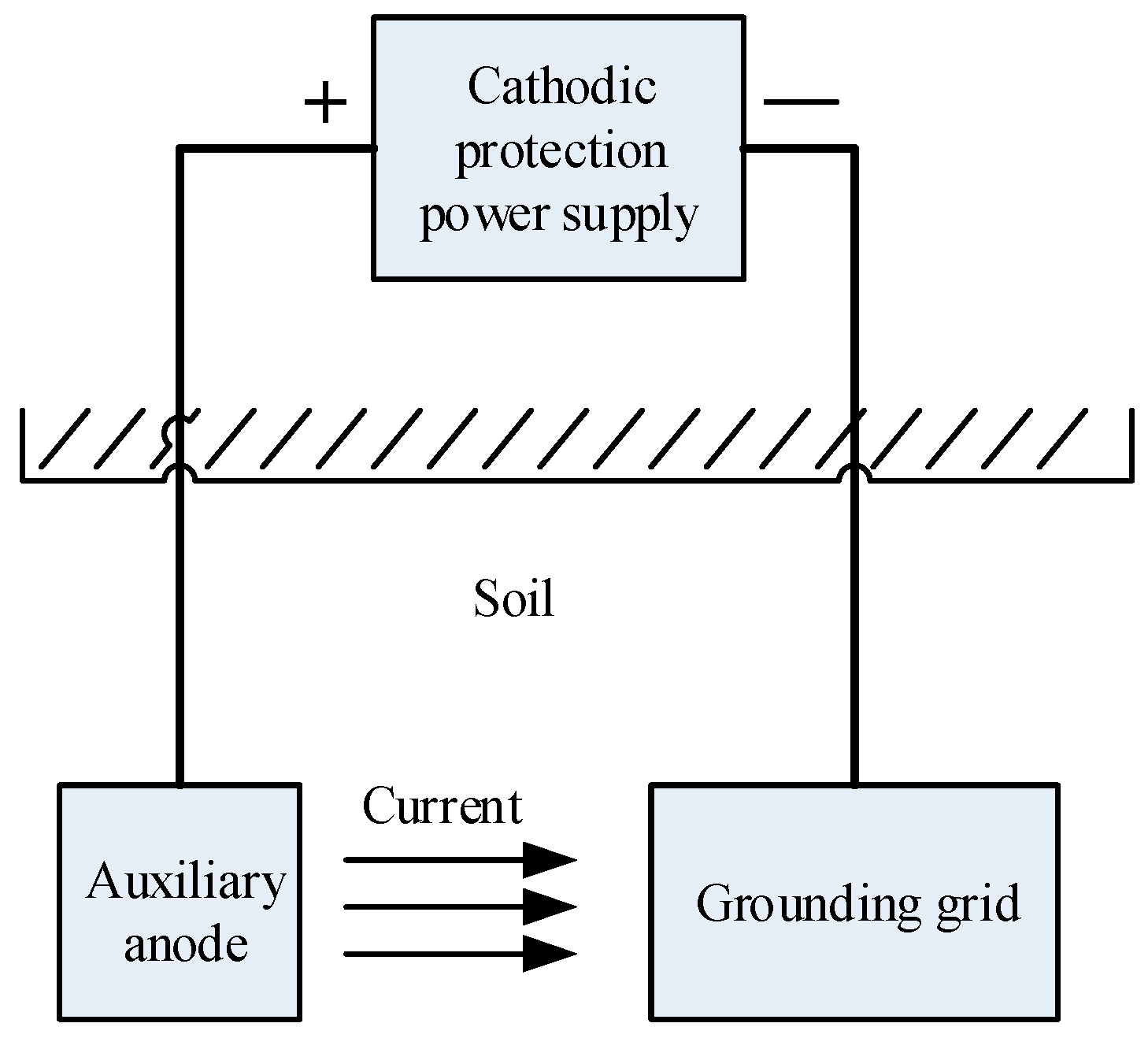
The auxiliary anode is an important part of the cathodic protection system and the grounding grid cathodic protection is more complicated. The model diagram is shown in
Figure 1. The potential distribution of the protected body is uniform and the design parameters of the anode are very important.
At present, in practical applications, the location of the embedding is determined mainly by experience or field test. In the already operating cathodic protection system, due to improper selection of the position, a protection body at a distance is not protected, and a protection body in the closer vicinity is over protected. The result is relocation and burying of the auxiliary anode, which is neither scientific nor economical. Through theoretical and experimental research on the design parameters of the auxiliary anode, it is found that reasonable anode design parameters should meet potential distribution requirements and ensure a small current density.
According to the purpose of cathodic protection design, all protected bodies reach the protection potential. For the protection of metal parts, the surface potential
of the protected metal should meet the purpose of corrosion protection
is the protection potential, and the value of
depends on the characteristics of the metal structure to be protected and the medium is selected with reference to relevant experiments and parameters.
In order to make the surface potential of all protected bodies in the region meet the above requirements, it can be solved in two ways. One is to rationally arrange and adjust the anode position; the other is to adjust the anode current output. The adjustment of the anode current output is easy to implement in engineering, as long as the current output of the current source is adjusted. The burying of the anode on the project requires a large investment and engineering quantity, such as the excavation of earthwork and laying of carbon beds. Therefore, it is almost impossible to adjust the position once it is fixed. Therefore, the research goal is to determine the optimal anode embedding position during the pre-construction, anti-corrosion design.
The finite element method can usually be used to solve the model. On the selected grid, the potential value at each junction of the cathode surface can be obtained.
Let the grounding net have
n nodes and the vector of the potential
at each node is
, marked as
, and it is defined as
Here,
is anode potential,
is the anode position,
,
,
are the projections of the anode on the X, Y and Z axes respectively,
is the grounding grid specification to be protected and a, b respectively represent the length and width specifications of the grounding grid;
is the number of anodes,
is the best protection potential.
In the two functions defined above, represents the degree of uniformity of the potential distribution, and represents the closeness of the calculated value of the average potential to the theoretical optimal value.
The following anode optimization problem is proposed: Find to satisfy . This represents the optimization of anode position, size and quantity as a multi-objective planning problem.
It is significantly different from the inverse problem commonly encountered in cathodic protection. First, it is not a single-objective planning problem but a multi-objective planning with two goals. Second, the functional in the objective function is not defined in terms of the difference between the observed value and the calculated value but is defined only by the calculated value. Since the definition of the two objective functions takes advantage of the concept of mean and variance, we can call this inverse problem model the mean variance model of the inverse problem of partial differential equations.
The idea for solving this inverse problem model is:
First, use the weighted average method to turn the multi-objective programming problem into a single-objective programming problem, let:
, find
satisfy:
Secondly, in solving this inverse problem, it is necessary to continuously solve the upper model for a given set of , which is actually a process of repeatedly solving the positive problem.
Aiming at the above characteristics, the calculation program for solving this inverse problem is designed by finite element method. The calculation program can be divided into two parts: the core of the program and the processing of the calculated data.
The core part of the program is to solve the mathematical model using finite element.
The data processing part of the program uses the potential value of each node on the cathode surface to calculate the value of the objective function . In the process of solving the inverse problem, it is necessary to frequently change the position and size of the anode and it is necessary to re-distribute the solution area frequently.
In summary, the finite element mathematical model of the auxiliary anode optimization design is equation (4), which is the basis of SAOA:
here, the limit value of the position of the coordinate source point of the
jth anode point of the grounding grid in the model.
The objective function and the variable are indirect implicit function relations, which requires that the selected optimization algorithm not only avoids the derivative of the objective function and the constraint function in the calculation process, but also uses the function values of the objective function and the constraint function. So the simulated annealing algorithm should be used to attempt intelligent optimization. The simulated annealing algorithm is essentially an intelligent optimization method. Directly oriented to optimization problems, it has a number of advantages over traditional optimization methods. The result is a good set of solutions rather than a single solution. This provides an alternative opportunity for users of the solution. Therefore, the algorithm is especially suitable for dealing with complex nonlinear optimization problems in engineering.
3. Auxiliary Anode Based on Simulated Annealing Optimized Finite Element Method
The following is an analysis of the traditional finite element loop algorithm, followed by the simulated annealing optimization finite element algorithm proposed in this paper and the calculation program for solving the model.
3.1. Traditional Finite Element Loop Algorithm Design Analysis
A four-layer cycle is set for anode position , anode size , anode number d, and ground grid specification to be protected.
In the first layer of circulation, the number of anodes is increased by a specific rule and gradually increases (for example, the number of anodes can be 1, 2, 3, 4, etc., sequentially increasing); in the second layer of circulation, each anode position is continuously changed according to specific rules; in the third layer of circulation, the amplitude of the anode size is changed according to a specific law; in the fourth layer of circulation, the ground grid specification is constantly changing.
The advantage of the loop algorithm calculation program is that the variation of with anode size, position, number, and grounding grid specifications can be quickly obtained; the disadvantage is that the anode size, position, number, and grounding grid specifications are not flexible enough to determine their specificity. When the value is can get the minimum value.
Based on the above reasons, the proposed finite element assisted anode algorithm based on simulated annealing can effectively solve the above problems.
3.2. Auxiliary Anode Design of Simulated Annealing Optimization Finite Element Algorithm
Simulated Annealing (SA) is an iterative adaptive heuristic probabilistic search algorithm that can be used to solve different nonlinear problems and optimize non-differentiable or even discontinuous functions [
20]. Simulated annealing algorithms can have a higher probability. The global optimal solution is obtained, which has strong robustness, global convergence, implicit parallelism and wide adaptability, and can handle different types of optimization design variables without any auxiliary information; on the objective function and there are no requirements for the constraint function. Utilizing the Metropolis algorithm and properly controlling the temperature drop process has great advantages for optimizing problem handling. Simulated annealing is a general optimization algorithm the process of which consists of the following three parts:
- (1)
Heating process. Its purpose is to enhance the thermal motion of the particles from the equilibrium position. When the temperature is high enough, the solid will melt into a liquid, eliminating the non-uniform state that the system originally existed.
- (2)
Isothermal process. For a closed system that exchanges heat with the surrounding environment and the temperature does not change, the spontaneous change of the system state always proceeds in the direction of reduced free energy and when the free energy reaches the minimum, the system reaches equilibrium.
- (3)
Cooling process. The thermal motion of the particles is weakened and the energy of the system is lowered to obtain a crystal structure.
In the algorithm, the heating process corresponds to the initial temperature of the algorithm. The isothermal process corresponds to the Metropolis sampling process of the algorithm. The cooling process corresponds to a drop in control parameters. The change in energy here is the objective function. The optimal solution we want to get is the lowest energy state. The Metropolis criterion is the key to the convergence of the SA algorithm to the global optimal solution. The Metropolis criterion accepts the worsening solution with a certain probability, which allows the algorithm to jump away from the local optimal trap.
The core idea of the algorithm is to set the calculated values of the k and k+1 times of the objective function in the minimization optimization problem to and respectively. If , the new point is accepted, and the algorithm starts the next iteration from . Until the given convergence criterion is satisfied; if , random processing is performed, and the acceptance of the new point is determined by (where r is a uniformly distributed random number on (0,1), and T is a control parameter). If the condition is true, is also accepted; otherwise, it is abandoned.
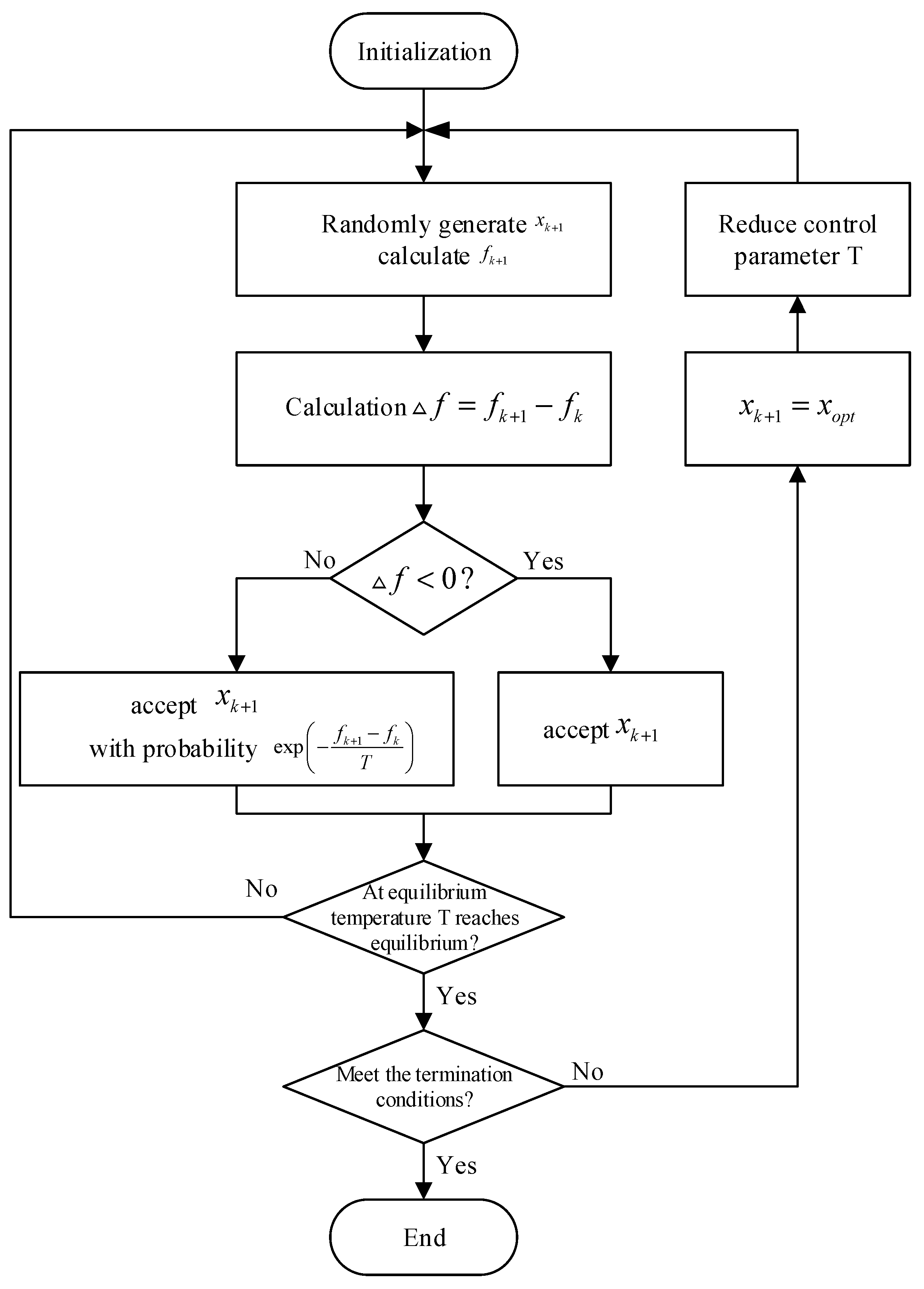
The flow chart of the optimization algorithm of the auxiliary anode system based on simulated annealing is shown in
Figure 2. It can be seen from
Figure 2 that the implementation of the algorithm needs to solve the technical problems such as the discretization processing of continuous variables, generation rules of new points, update mechanism of control parameters, termination rules of algorithms and the selection of algorithm parameters.
- (1)
Rules for the generation of new points:
Let X be the solution at a certain moment, r is a random number between [0, 1], and the new solution is:
By adopting the above search strategy, the randomness of the algorithm is satisfied and the ergodicity of the space is achieved.
- (2)
Update mechanism of control parameters:
The update mechanism of the control parameters, that is, the falling rule of the control parameters, is used to modify the control parameter values in the outer loop. Currently, the most commonly used control parameter update function is exponential de-warming, i.e.,
In the middle,
.
The steps of the optimization algorithm for the auxiliary anode system based on simulated annealing are as follows:
- (1)
Solve the model (4) for the established finite element method and select
as the initial state. The parameters of the established grounding grid auxiliary anode system are:
,
,
,
, let
, and set the initial temperature T = 100. Let
. The termination condition is
- (2)
Let , call the Metropolis sampling algorithm with T and , return the state S as the current solution of the algorithm, and (i is the current time).
- (3)
Cool down in a certain way, i.e., , where , .
- (4)
Check the termination condition, if yes, go to step (5), otherwise go to step (2).
- (5)
The current solution is the optimal solution of the finite element model, and the output result is stopped.
The Metropolis sampling algorithm is described as follows:
- (1)
When is made, the current solution , at temperature T, performs the following steps.
- (2)
A neighbor subset is generated according to the state S in which the current solution is located, and a new state is randomly obtained from as the next candidate solution, and the energy difference is calculated.
- (3)
If , accept as the next current solution, otherwise, accept as the next current solution with probability . If is accepted, then let , otherwise .
- (4)
, check whether the algorithm satisfies the termination condition. If yes, go to step (5), otherwise go to step (2).
- (5)
Return to and end.
4. Simulation Experiments and Results Analysis
Taking the grounding grid
as an example, the buried depth is 0.8 m, the grounding trunk is
galvanized flat steel, the electrical conductivity is
, the soil conductivity is
, the optimal potential is
= −0.9 V, the weighting coefficient
= 0.6,
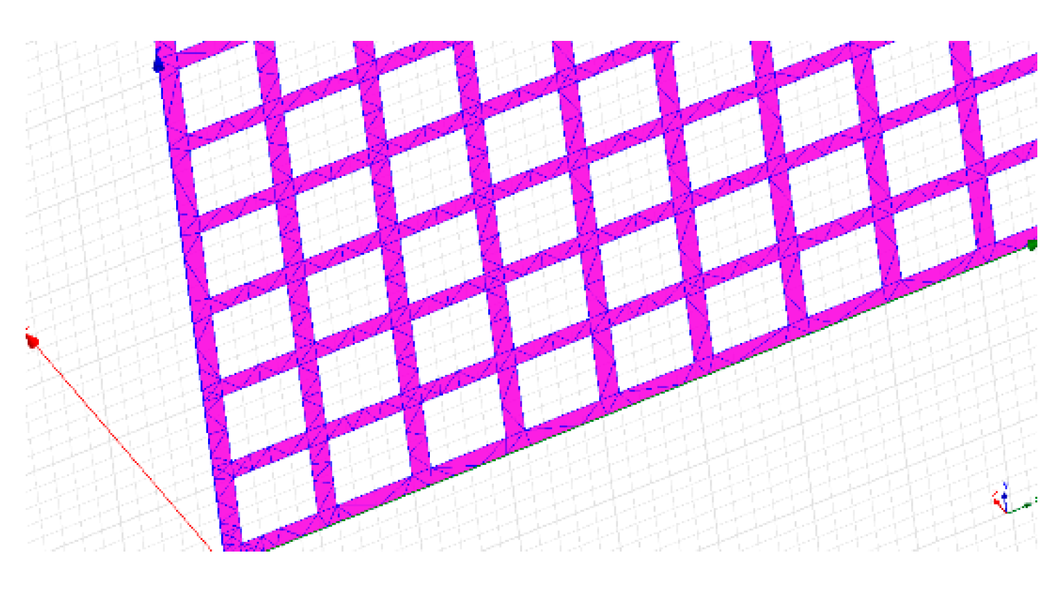
= 0.4, according to the above SAOA algorithm, the schematic diagram of the surface of the grounding grid after the cathodic protection model is divided as shown in
Figure 3.
The SAOA algorithm is used to optimize the calculation and the optimal solution for obtaining the optimal protection effect of the grounding grid cathodic protection system is: anode potential
; number of anodes
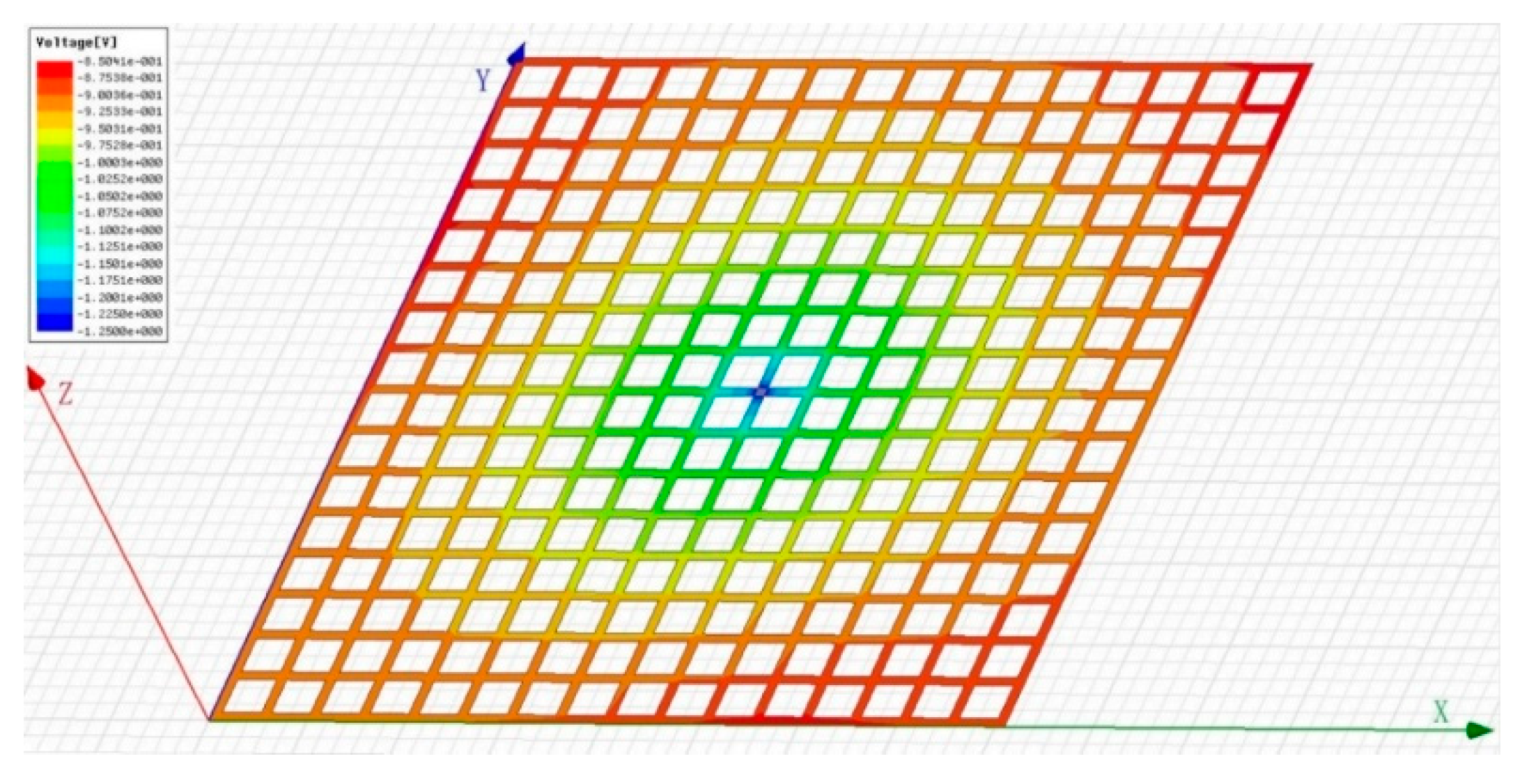
; positions of three anodes are A (0, 156.8, 83.7), B (132.6, 0, 78.6), C (200, 200, 64.2). At this time, the distribution of the surface potential of the grounding grid is as shown in
Figure 4. The maximum potential of the grounding grid surface is −0.85 V and the minimum potential is −1.25 V, which meets the engineering requirements.
Figure 4 shows the distribution of the surface potential of the grounding grid in a three-dimensional space, which is represented by a different color, from red to blue, indicating that the potential gradually becomes smaller.
According to the SAOA algorithm, when the anode potential
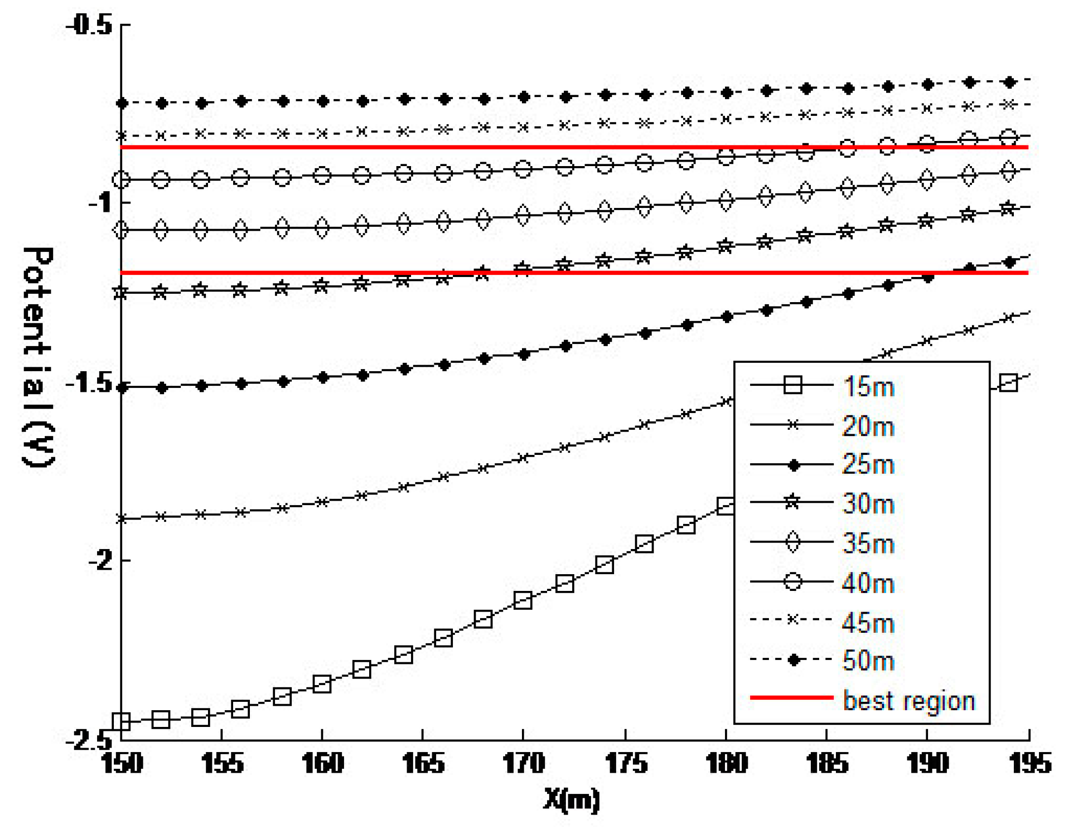
, the anode is placed 5 to 50 m below the grounding grid and the grounding grid potential distribution caused by different positions is shown in
Figure 5.
It can be seen from
Figure 5 that as the depth of the anode is increased, the average potential and variance of the surface of the grounding grid become smaller.
The finite element simulated annealing algorithm (SAOA), variable scale method (DFP) and genetic algorithm (GA) are used to solve the above grounding grid, respectively. The optimization calculation results of various algorithms are shown in
Table 1.
It can be seen from
Table 1 that in the optimization method of the grounding grid cathodic protection system, the design accuracy based on the simulated annealing algorithm is 1.12% higher than that based on the genetic algorithm and the design accuracy is 1.64% higher than that based on the variable scale method.
