1. Introduction
In a wind power generation system (WPGS) scheme, rectifiers are used to extract power from a renewable energy source in a controlled manner [
1], which is then delivered to the grid by means of a voltage source inverter (VSI). The most commonly used topology for this application is the back-to-back converter, which achieves bidirectional power flow [
2]. Nevertheless, when bidirectionality is not needed, using an uncontrolled rectifier + three level boost chopper represents a cheaper alternative than the former.
Three level boost chopper has a large number of advantages compared with the conventional boost converter, such as: (a) comparing to the previous boost converter, the inductor current ripple of the boost-TL converter is lower, reducing the generator torque ripple; (b) the voltage stress of the power device is less than that of the conventional boost converter, so the output voltage of the generator and the capacity of the converter can both be increased; (c) in the case of the same inductor current, the switching frequency is half that of the conventional boost converter, so the switching losses are less; (d) the boost-TL converter boosts the DC output voltage from the rectifier at low speeds, so it also allows the wind power generator to operate over a wider speed range. Therefore, the boost three-level converter is widely adopted in modern power electronics apparatus. In [
3], the MPPT and the methods of the voltage balancing control for the boost three-level converter are proposed, however, MPC is not adopted. In [
4], a novel predictive controller for a series-interleaved multicell boost three-level PFC converter has been presented.
In wind power generation systems, multilevel converter topology has received increasing attention in order to meet the ever-increasing stand-alone capacity of wind turbine generators and the ever-increasing current and voltage levels of converters. The neutral-point-clamped (NPC) inverter and T-type inverter are commonly adopted in the three-level inverter topology, compared with the NPC inverter, the T-type three-level structure also has many advantages, such as: (a) small number of components; (b) the control signal has no stop sequence problem and is easier to control; (c) low switching loss and high efficiency; (d) less driving power; and (e) in the aspect of the commutation path, the conversion paths between the outer tube Sa1/Sa2 and the inner tube Sa3/Sa4 are all the same, and the problems of the stray inductance and the voltage peak are less.
With the development of wind power systems, the converter circuit of uncontrolled rectifier + boost chopper + PWM inverter has attracted more and more interest of scholars from various countries. In the circuit, the rectifier part adopts a diode uncontrolled rectifier, the boost converter in the middle DC link raises the DC voltage, and the inverter part adopts a PWM three-phase bridge inverter. Compared with back-to-back PWM converters, the topology of the generator-side converter has been simplified, a number of power switch devices and their driving circuits are omitted, the switching loss of the power device is reduced, the cost is reduced, and the reliability of the whole system is enhanced.
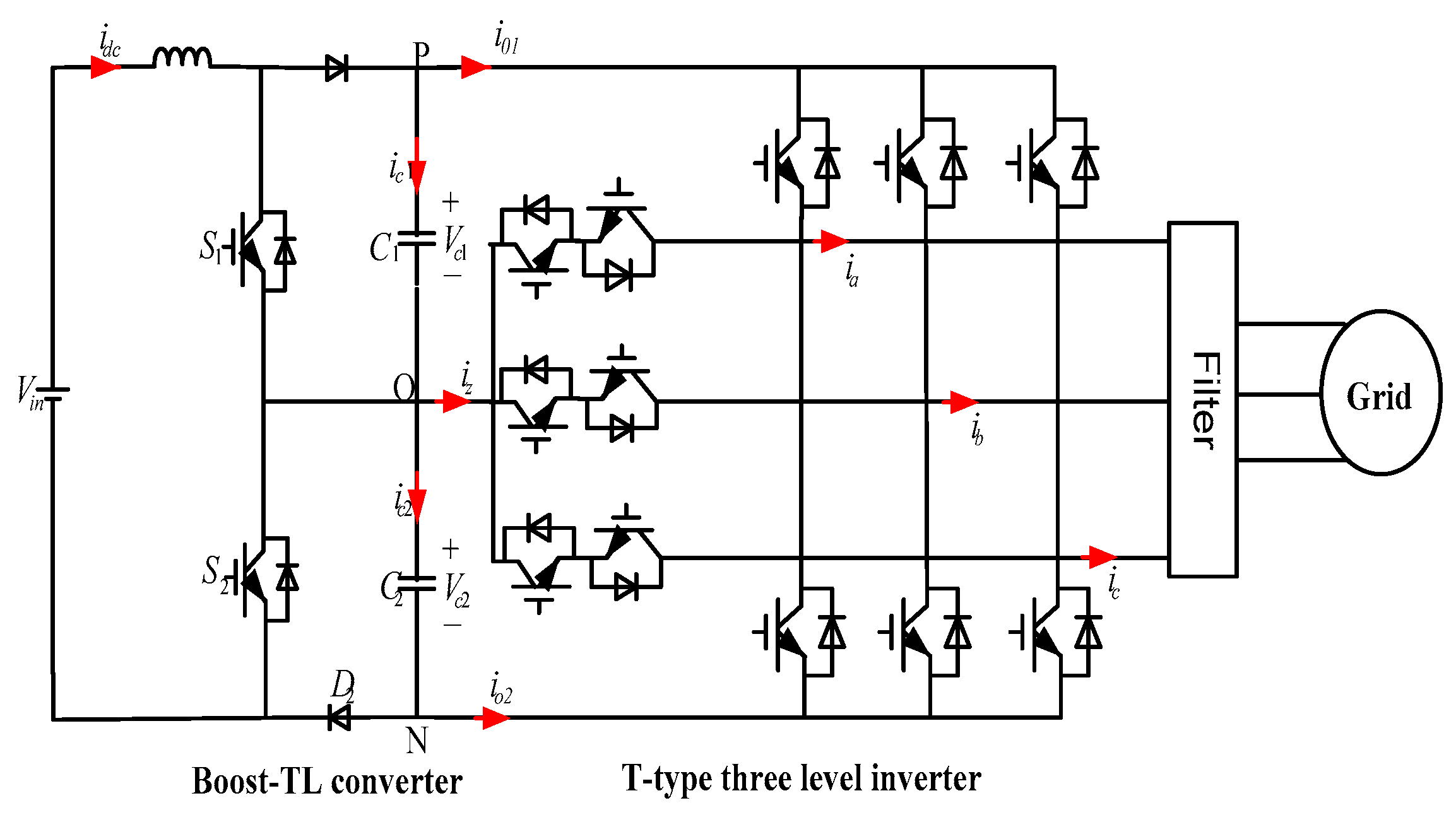
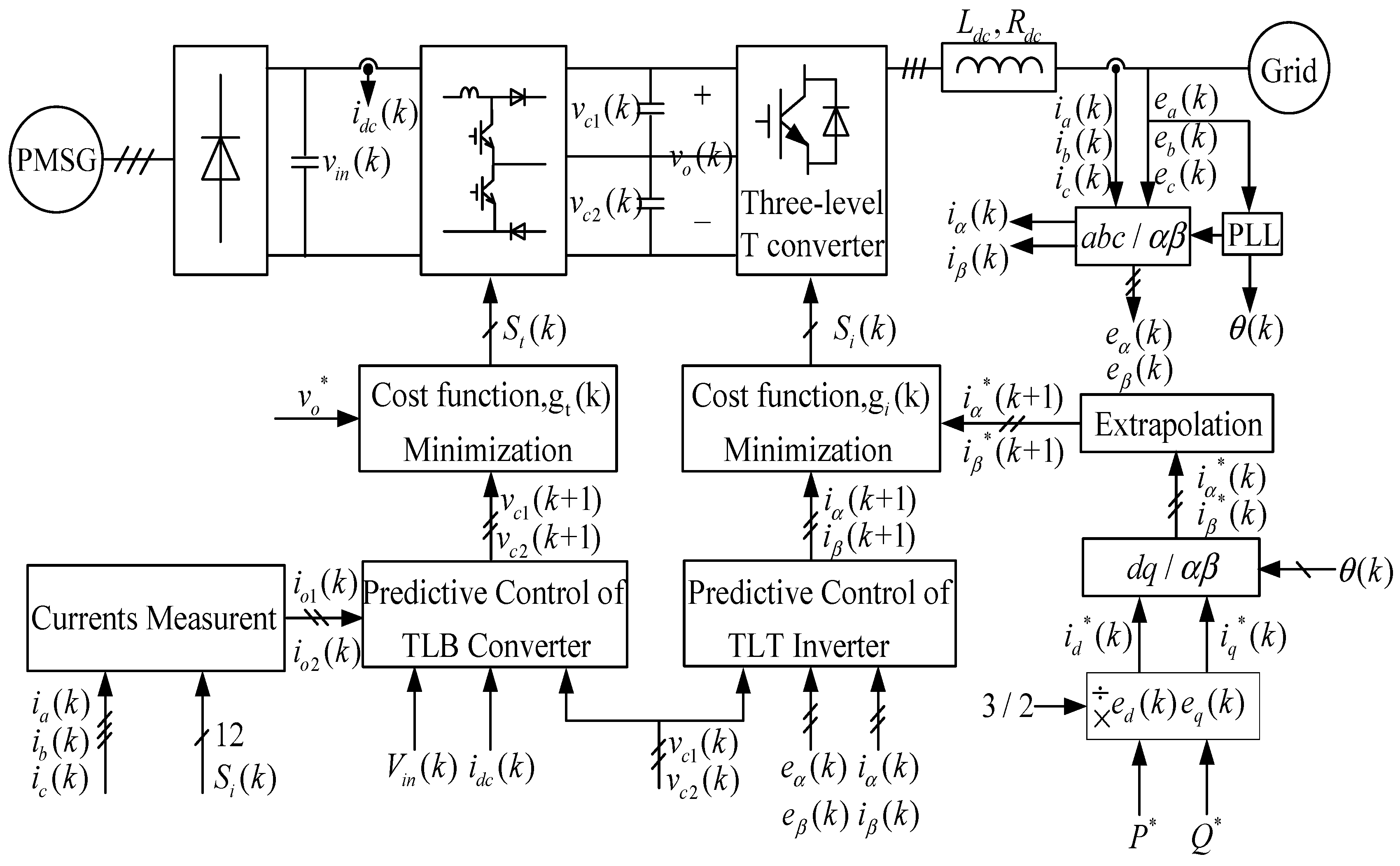
Combining the advantages mentioned earlier, a topology based on boost three-level converter (BTL converter) and T-type three-level inverter cascaded for wind power generation system is proposed, as shown in
Figure 1.
Since FCS-MPC has an intuitive concept, flexible control, no modulator, no parameter setting, and fast dynamic response, it can also effectively deal with the system of non-linear links and various restrictions and other advantages, so it has become a hot research topic. At present, FCS-MPC has been widely used in various power electronic converters. Compared with proportional integral control, MPC has superior performance and has attracted much attention. First presented in [
5], MPC deals with linear and nonlinear models and provides maximum realizable bandwidth. For the boost converter, the predictive control method has been deeply studied. Reference [
6] Yaramasu, V. and Wu, B. adopted predictive control of BTL using a dynamic model of inductance current and DC bus voltage. Adopted regression methods in [
7] to predict the next cycle current of digital controller delay compensation by Baggio, J., etc. In [
8], the FCS-MPC method is adopted to reduce the CMV and balance the NP voltage with fast dynamics of the three-level T-type inverter by Xing, X., etc. In [
9], the modified model predictive control algorithm for the high efficiency with reduced switch stress t-type three-level inverter with the neutral point clamped is presented by Abdel-Rahim, O., etc. In [
10], a radial basis function neural network optimization model predictive control (MPC) was proposed by Han, B., etc. for large wind turbines, which meets the requirements of the specified operation region. Reference [
11] Wang, X. and Sun, D proposes a three-vector-based low complexity model predictive direct power control strategy for doubly-fed induction generators (DFIGs) in wind energy applications, which improve the steady-state performance and achieves error-free control. In [
12], the proposed sensorless method by Bayhan, S., etc. offers as a model-free solution, the MPC strategy has been used as a current controller to overcome the weaknesses of the inner control loop and considers the discrete-time operation of the VSC.
In this paper, a new predictive current control method without any kind of linear controller or modulation technology is proposed for the BTL and three-level T-type inverter cascaded topology, with stable performance of THD improved significantly.
The structure of this paper is organized as follows: the principle of boost-TL converter and the principle of the T-type three-level inverter are introduced in
Section 2 and
Section 3, respectively; the predictive current control strategy is presented in
Section 4; the simulation and experimental implementation and validation are shown in
Section 5; and the conclusion of the paper can be found in
Section 6.
2. The Principle of Boost-TL Converter
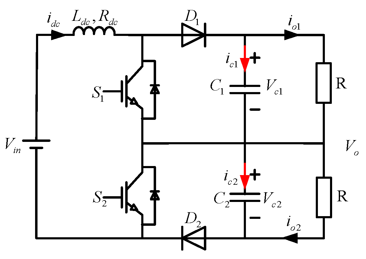
Figure 2 shows the main circuit of the boost-TL converter.
and
are the main power switches,
L is the boost inductor,
and
are for the freewheeling diode,
and
are the voltage divider capacitors, and
R is the load;
and
are the capacitor voltage,
is the current flowing through the boost inductor, and
is the output voltage.
It is assumed that the switch, the diode, the inductor, and the capacitors of the circuit are ideal components. The drive signals and have a phase difference of 180° to reduce the inductor current ripple and the output voltage ripple. = , and it is large enough to divide the supply voltage evenly, and the ratio of ripple to the output voltage is small enough to be negligible.
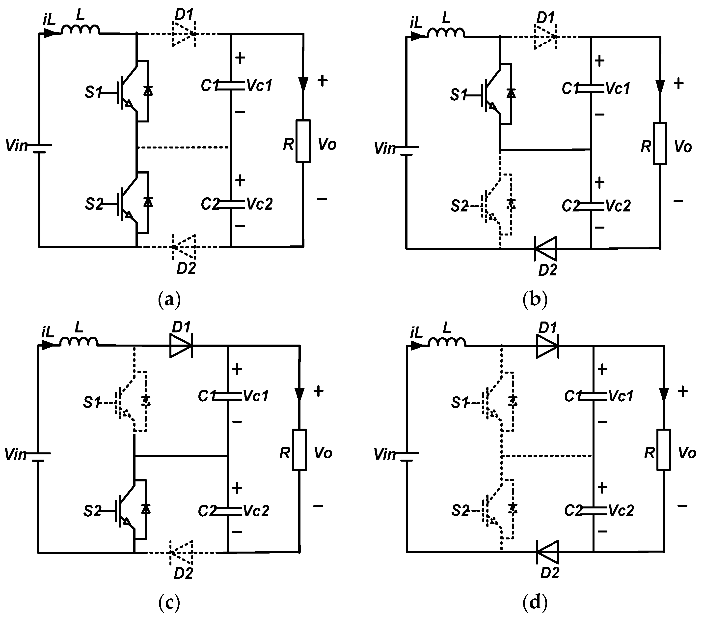
When the duty cycle of the switch is d < 0.5 or d > 0.5, the operation mode of the converter is different. The following are analyzed separately. In a switching cycle, the four operating modes of the circuit are described as follows:
- (1)
Mode 1: switch
,
are on, diode
,
are off, inductance current increases linearly, the inductor stores energy, and the capacitors
,
supply energy to a load, as shown in
Figure 3a.
- (2)
Mode 2: switch
is on,
is off, diode
is off,
is on, the input voltage
provides energy to the load R through a loop composed of inductor L,
, and
, as shown in
Figure 3b.
- (3)
Mode 3: switch
is off,
is on, diode
is on,
is off, the input voltage
provides energy to the load R through a loop composed of inductor L,
, and
, as shown in
Figure 3c.
- (4)
Mode 4: switch
is off,
is off, diode
is on,
is on, the input voltage
provides energy to the load R through a loop composed of inductor L,
, and
, as shown in
Figure 3d.
It can be seen that when the duty cycle
d < 0.5, the operating modes include modes 2, 3, and 4, and there is no mode 1; when the duty cycle
d > 0.5, modes of operation include modes 1, 2, and 3, and no mode 4. When the switch duty cycle
d < 0.5, according to the voltage voltage-second balance at both ends of the inductor during a switching cycle, the following results can be obtained:
When the switch duty cycle
d > 0.5, for the same reason, according to the voltage voltage-second balance at both ends of the inductor during a switching cycle, the following results can be obtained:
According to the above formula, which can be introduced into the relationship between the input and output and is still satisfied by
, which means when the duty cycle
d > 0.5 and
d < 0.5, the converters have the same input-output relationship. If the output capacitance is equally divided, the output voltage, which is
, and
, can be further obtained:
It can be seen from the above formula that the boost-TL converter has the same input and output voltage relationship as the traditional boost converter.
3. Principle of the T-Type Three-Level Inverter
In recent years, The T-type three-level inverter has been widely used in photovoltaic (PV) inverters, power factor correction (PFC) rectifiers, automatic rectification, and other low-voltage systems [
13].
Figure 4 shows a simplified circuit for a T-type inverter. T-type inverters use the same switches as conventional two-level inverters because these switches (
and
) have to block the full DC link voltage. A bidirectional switch is connected between the neutral point and each output. Unlike the half-bridge switches (
and
), the bidirectional switches (
and
) only need to block half the DC link voltage. Therefore, the devices with lower voltage ratings can be used. A neutral point clamp inverter (NPC) uses two switches connected in series to block the voltage across the DC link. On the other hand, T-type inverters use a single switch to block the voltage across the DC link. Therefore, the T-type inverter conduction loss is greatly reduced compared to that of the NPC inverter. The T-type inverter reduces switching losses and switching noise because the neutral switch operates below half the DC link voltage. Therefore, the total losses in a T-type inverter are the lowest among those of the two-level, NPC, and T-type inverters at medium switching frequencies (4–30 kHz).
Considering the switch combinations based on
Table 1, this configuration allows three voltage levels related to neutral 0 to be generated at the output of phase x.
For the T-type inverter, the number of switching states is 27, including 19 different voltage vectors, as shown in
Figure 5, where some switching states are redundant and generate the same voltage vector. Compared with the two-level inverter, the three-level T-type inverter shows a higher number of switching states. Greater possible incentive mechanisms allow for additional degrees of freedom, and several combinations of cost functions can be considered [
14].
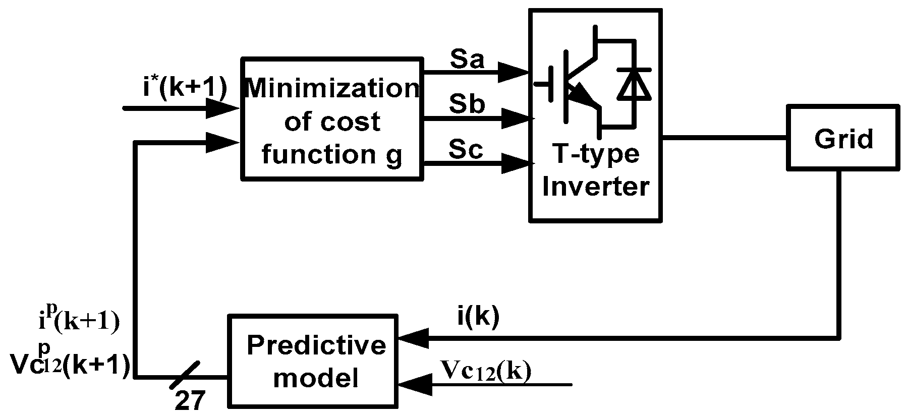
The general predictive control scheme is adopted in the T-type inverter [
15]. The behavior of the system can be predicted for every possible switching state of this converter. We choose to minimize the switching state for a given cost function for use in the next sampling interval. Compared with the two-level inverter, the T-type inverter has a higher number of switching states. A larger set of possible drivers allows for additional degrees of freedom, and several combinations of cost functions can be considered. Considering the requirements of the control system, the characteristic and its applications of this topology are studied and compared with the classical PWM linear control algorithm, including load current reference tracking, balancing the DC link capacitor voltage, reducing the switching frequency, and so on [
16]. With the development of microprocessor technology [
17], the predictive control has been widely applied in power systems. Finite control set model predictive control (FCS-MPC) is more suitable for power electronic converters. The controller is intuitive and easy to implement, and can be used in a number of systems with constraints and/or non-linearly.
In this article, the control strategy is summarized as follows: 1. Define a cost function; 2. Create a transformer model and its possible switch states; and 3. Create a grid model for forecasting. A discrete time model of the load is required for the predicting behavior of the evaluated variable by a cost function, that is, the grid current.
5. Simulations and Experimental
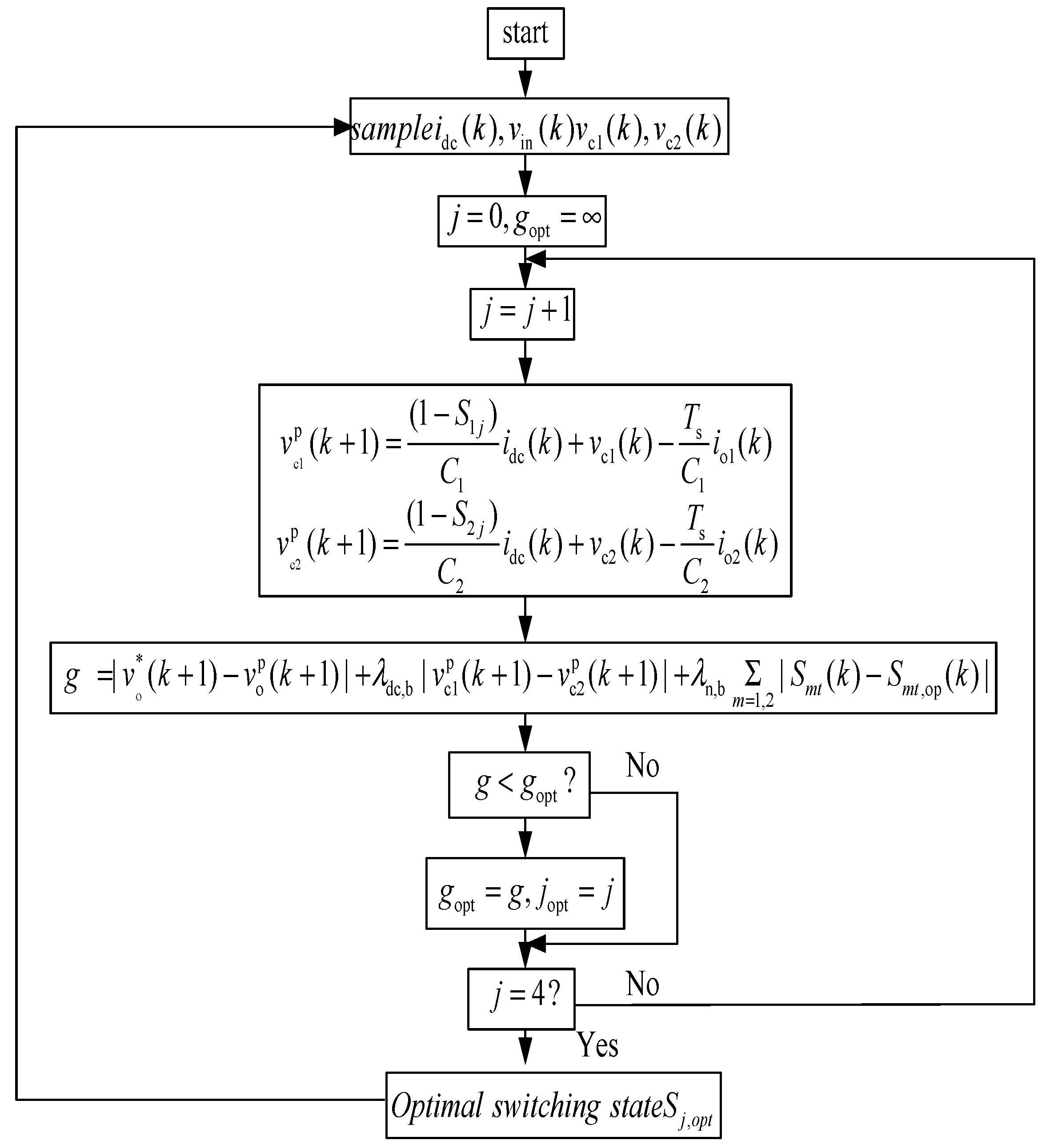
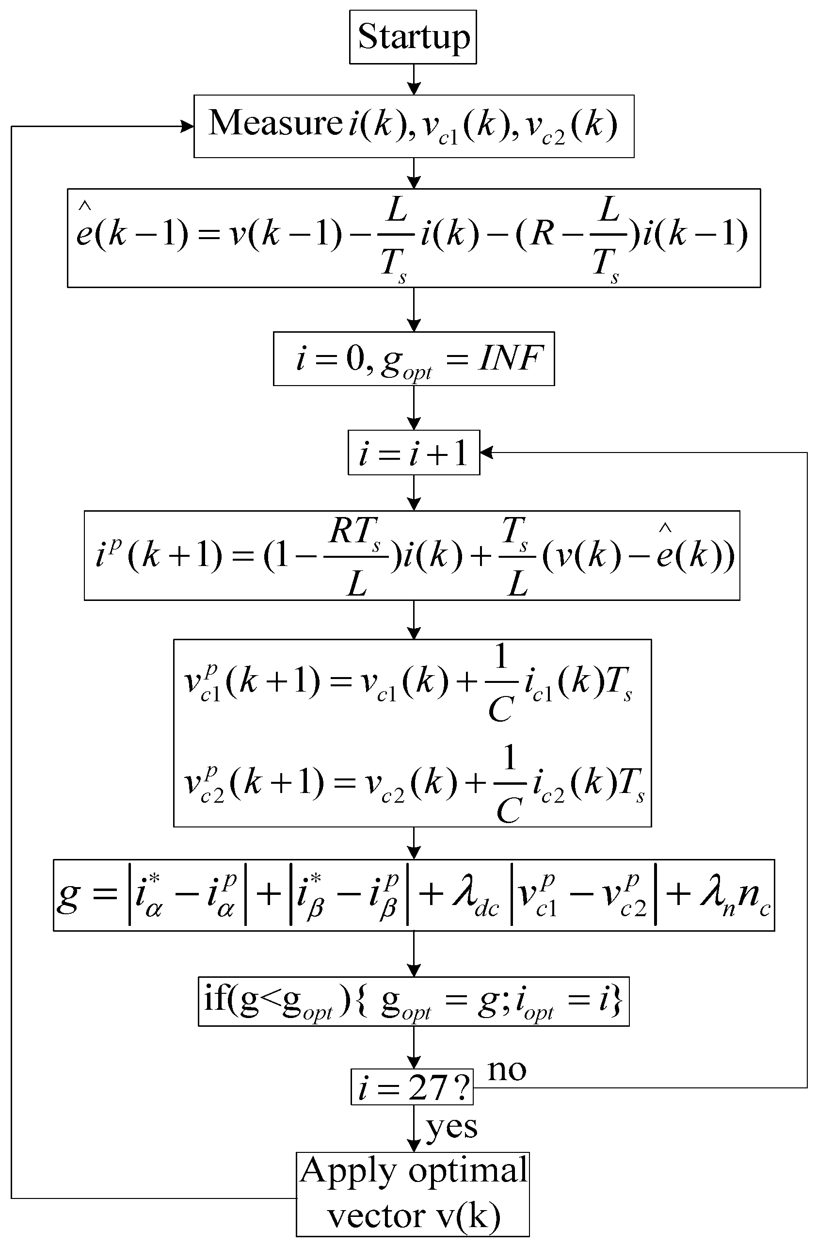
The control strategy of the predictive current is simulated in MATLAB(R2013), containing the code of the control algorithm, as shown in
Figure 8. When experimentally implementing predictive control, the same procedure was rewritten in the C language and the alpha and beta currents were calculated. In the MATLAB/SIMULINK environment, the load current prediction (Equation (14)) and back EMF estimation (Equation (17)) are considered. The system parameters
,
,
, and
have been taken into account for the simulations. The current and voltage in one of the phases of the load are simulated for a sampling time
. There is no steady state error from the current, but there is an obvious ripple. The ripple is significantly reduced when the smaller sampling time
is adopted. However, by reducing the sampling time, the switching frequency increases, as shown in the load voltage comparison shown in Figure 13. The inverter output phase voltage is shown in
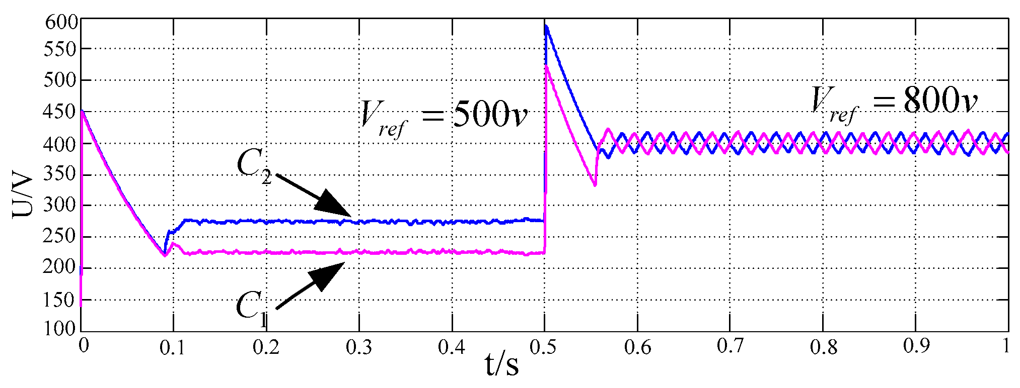
Figure 11. When the reference voltage value rises from 500 V to 800 V, the change of the capacitance voltage is shown in
Figure 12.
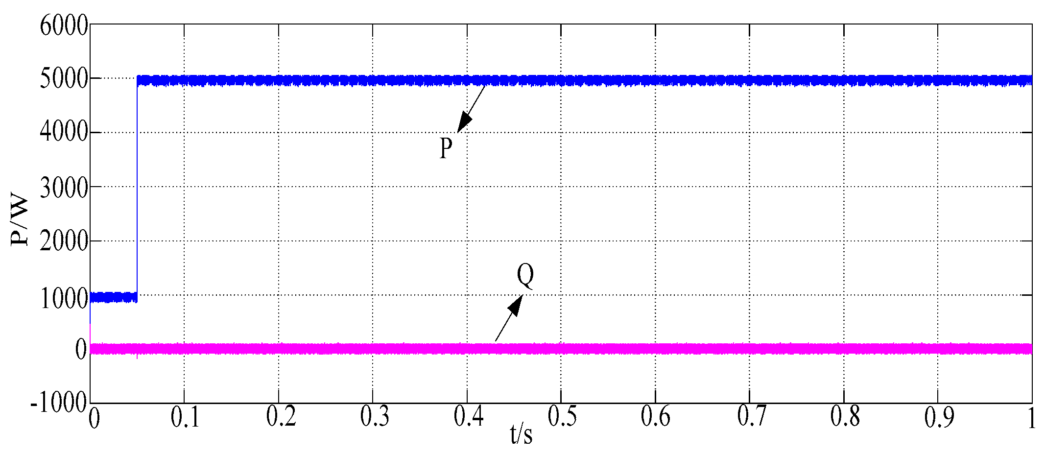
As shown in
Figure 13, the value of the reference power is changed at
, and the corresponding reference current phase can still stably track the grid voltage phase, and the response speed is fast.
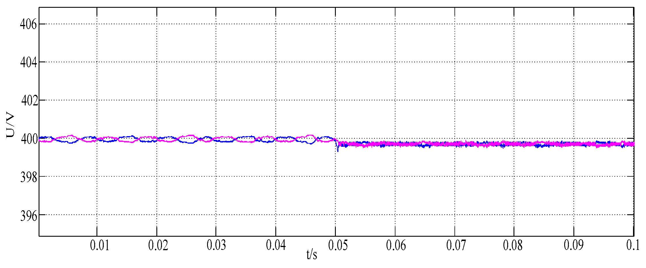
With the change of the reference current, the voltage of the divider capacitor becomes more and more stable when the weight factor increases, and the two are close to equal, as shown in
Figure 14.
When changing the value of the reference power, the system can respond quickly. As shown in
Figure 15.
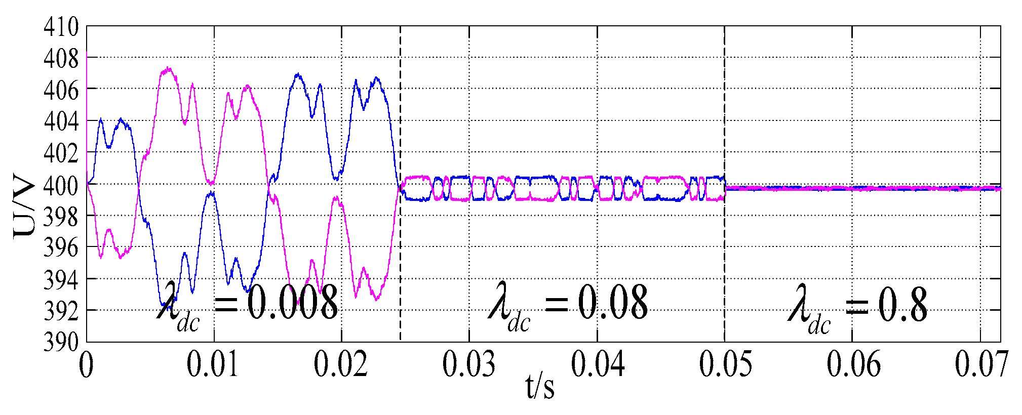
At the same time, the control level of the voltage-dividing capacitance increases with the increase of the weighting factor when observing the increase of the magnitude of the weight factor of the division of the voltage-dividing capacitance, which is the same as the conclusion, as shown in
Figure 16.
As shown in
Figure 17, it is obvious to say that the rise of the weighting factor of the current tracking can optimize the THD from 0.15% to 0.10%.
The proposed control method requires a higher sampling or data acquisition frequency. Given the new technologies available for DSP, the foregoing fact should not be a problem. It is worth mentioning that the sampling time is always a fixed position in the sampling period, to facilitate the acquisition of measurement data and to avoid the problem of the switching the power devices. The algorithm is implemented on a Texas Instruments DSP using the same sampling frequency. The algorithm was implemented on the Texas Instruments TMS320F2812 DSP using the same sampling frequency, and similar results in processing time were achieved. The experimental platform is shown in
Figure 18 to determine whether the driving circuit can work normally, which plays a key role in the whole system’s working state. First, according to the working principle of the driving circuit analyzed above, we designed and built the corresponding driving module. The drive signal is shown in
Figure 19.
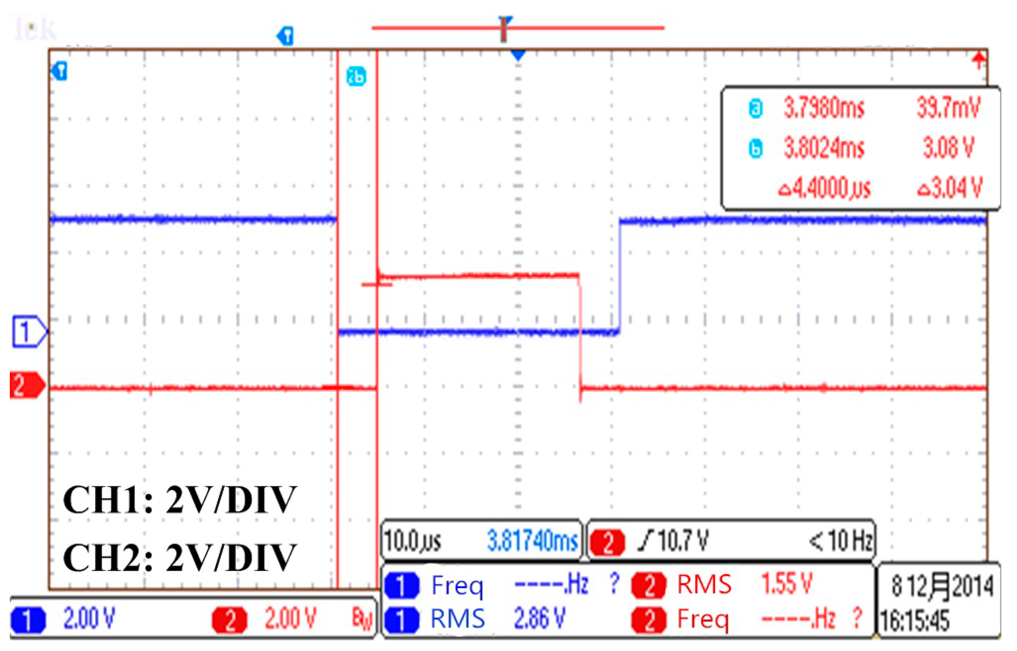
The waveforms in the same bridge arm are supposed to be complementary to each other. In order to avoid the two tubes in the same bridge arm conducting at the same time,
dead time is added in the driving signal between
,
and
,
as shown in
Figure 20.
As shown in
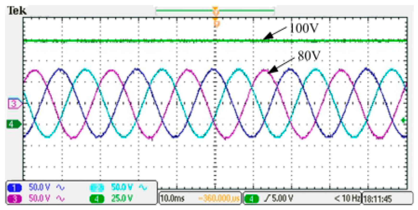
Figure 21, the input DC voltage is 50 V. Adjusting the duty cycle, the DC bus voltage is increased to 100 V, and the inverter output voltage at this time is 80 V. In order to ensure the safety of experimental operation, the voltage amplitude of AC voltage regulator is also transferred to 80 V, the grid connection is realized after synchronization control.
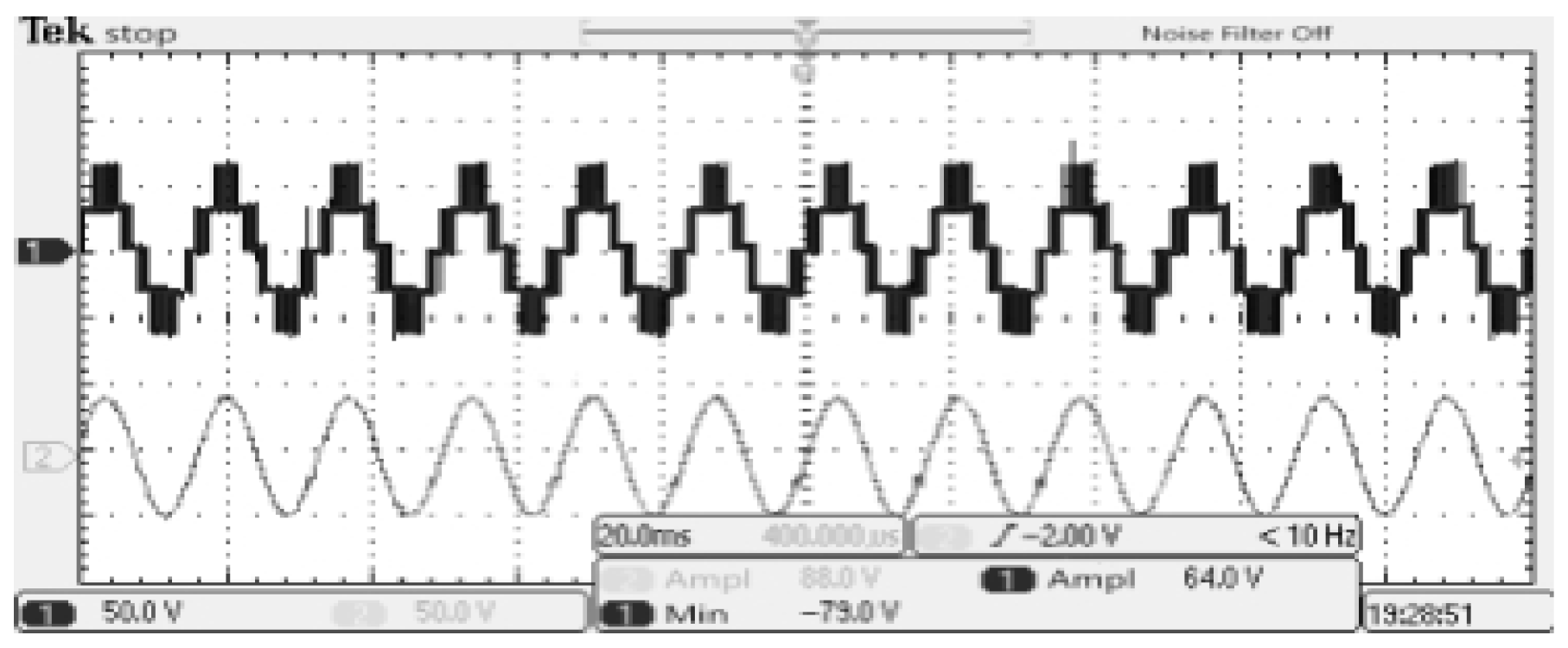
The waveforms of the output line voltage and current are shown in
Figure 22. All of these experimental waveforms demonstrate the correctness and effectiveness of the proposed control scheme.
