
Liquid Crystal Microlenses for Autostereoscopic Displays


Abstract
:1. Introduction


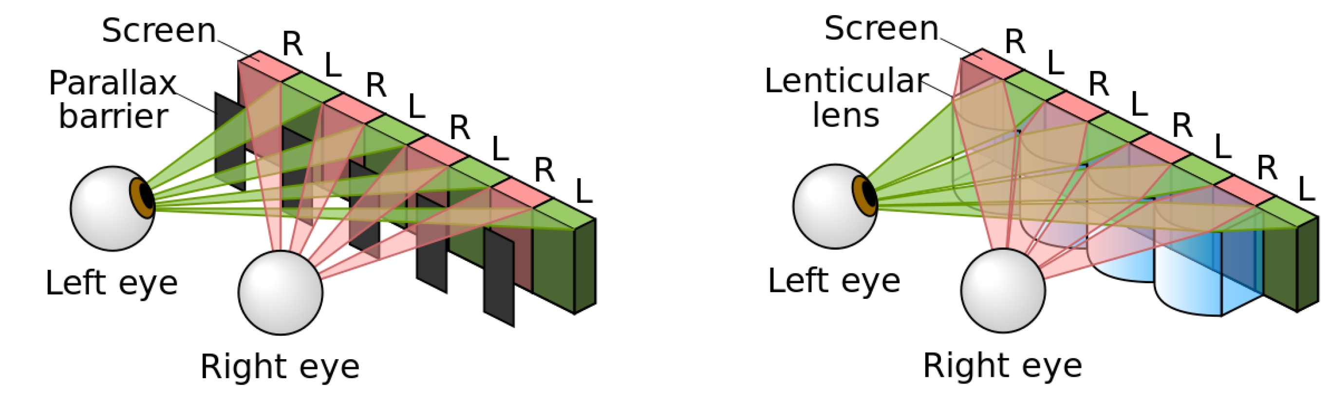
2. State of the Art of Spatial Multiplexing Technique

| Product | Company | Technology | Resolution | Mode | Year |
|---|---|---|---|---|---|
 | Sharp 3.4″ (3DS) | Dynamic parallax | 480 × 854 | 2D/3D | 2011 |
 | Toshiba 55″ (55ZL2G) | Fixed Lenticular array | 3840 × 2160 (4K) | 2D/3D | 2012 |
| Unknown | Toshiba 15″ (Unknown) | LC Lenticular array | 4K | 2D/3D/4K | 2015–2016 |
- The loss of resolution is solved through very high-resolution displays (QFHD (quad full high definition), 3840 × 2160 pixels). Moreover, the lenses are placed with a small angle to distribute the loss of resolution vertically and horizontally [24].
- Another common problem is the non-uniformity of the light coming from pixels. The problem is caused by the darker spaces of the pixels that generate bright and dark areas. An observer looking at different angles will notice a change in the image brightness under certain positions. There are three methods to solve this: place the lenses with a convenient angle, adapt the focal distance, and modify the width of the lenses to obtain fractionated views [25].
- Another significant problem are aberrations caused by manufacturing defects. Aberrations cause a non-uniform distribution of the intensity. However, thanks to improvements in various processes, the non-uniformity of the lenses can reduce the crosstalk to values ranging from 2%–7% [26].
| Characteristic | Fixed Parallax | Dynamic Parallax | Passive Parallax | Fixed Lenses | Active Lenses | Passive Lenses |
|---|---|---|---|---|---|---|
| Brightness 2D * | 45% | 45%–85% | 45% | >95% | >95% | >95% |
| Brightness 3D * | 45% | <20% | <20% | >95% | >95% | >95% |
| Contrast | 1:1000 | - | - | 1:1500 | - | - |
| Crosstalk | >2%–3% | >2%–3% | >2%–3% | <1% | <1% | <1% |
| Thickness | 0.5 mm | 1.13 mm | 1.65 mm | 0.7 mm | 1 mm | 1.1 mm |
| Voltage 2D | - | 0 V | 0 V | - | Depend on the topology | 0 V |
| Voltage 3D | - | 3.3 V | 3.3 V | - | 0V | 3.3 V |
| Switching time | - | <100 ms | <100 ms | - | Several seconds | <100 ms |
| Multiplexing of 2D/3D areas | - | Differences ×3–×5 in brightness | Differences ×2 in brightness | - | Yes | Yes |
3. Liquid Crystal Microlenses for Autostereoscopic Displays
3.1. Curved Surface
- Curved ITO: Consists of a curved electrode of indium titanium oxide (ITO). This structure has the same problems as dual-voltage lenses which require a complex fabrication process [50]. Moreover, no reports at micrometric scale have been reported. For these reasons, they are less relevant to this list.
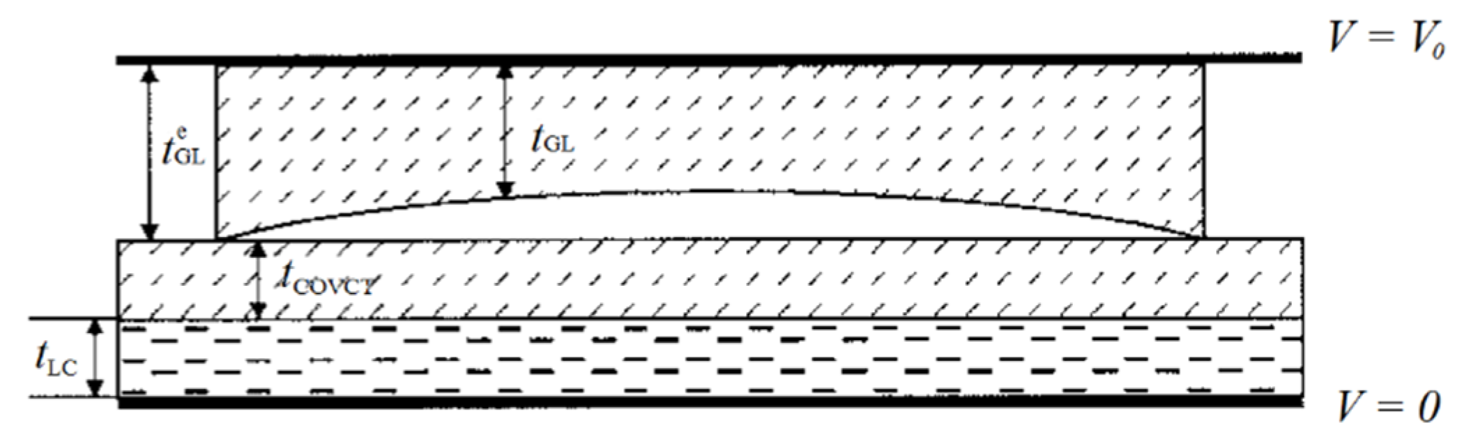
- Curved glass: These lenses were the first LC lenses, a cavity of glass [51]. Although it could be guessed that this old design would be overpassed by new technologies, it is, surprisingly, still used. The main reason is the application of this design to autostereoscopic devices. As mentioned above, this particular technique was not further developed because it had low response time and problems of lack of homogeneity. However, new proposals have reported LC to work as microlenses (immersed polymer microlenses) [52]. This reduces the necessary thickness. Moreover, techniques of LC multilayers further reduce the thickness and the inhomogeneity (Figure 7). When a dielectric layer and a LC layer are sandwiched between two continuous electrodes, the thickness variance of the dielectric layer gives rise to an inhomogeneous electric field in the LC layer [53].

- Curved Photoresin: In this approach, the photoresin has a spherical or cylindrical shape and is surrounded by the LC material [54]. Its main disadvantage is the complex fabrication process. Another option is to produce spherical cavities of photoresin and filled them with LC. This topology has been proposed to work in autostereoscopic devices with switchable 2D/3D mode:
- ➢
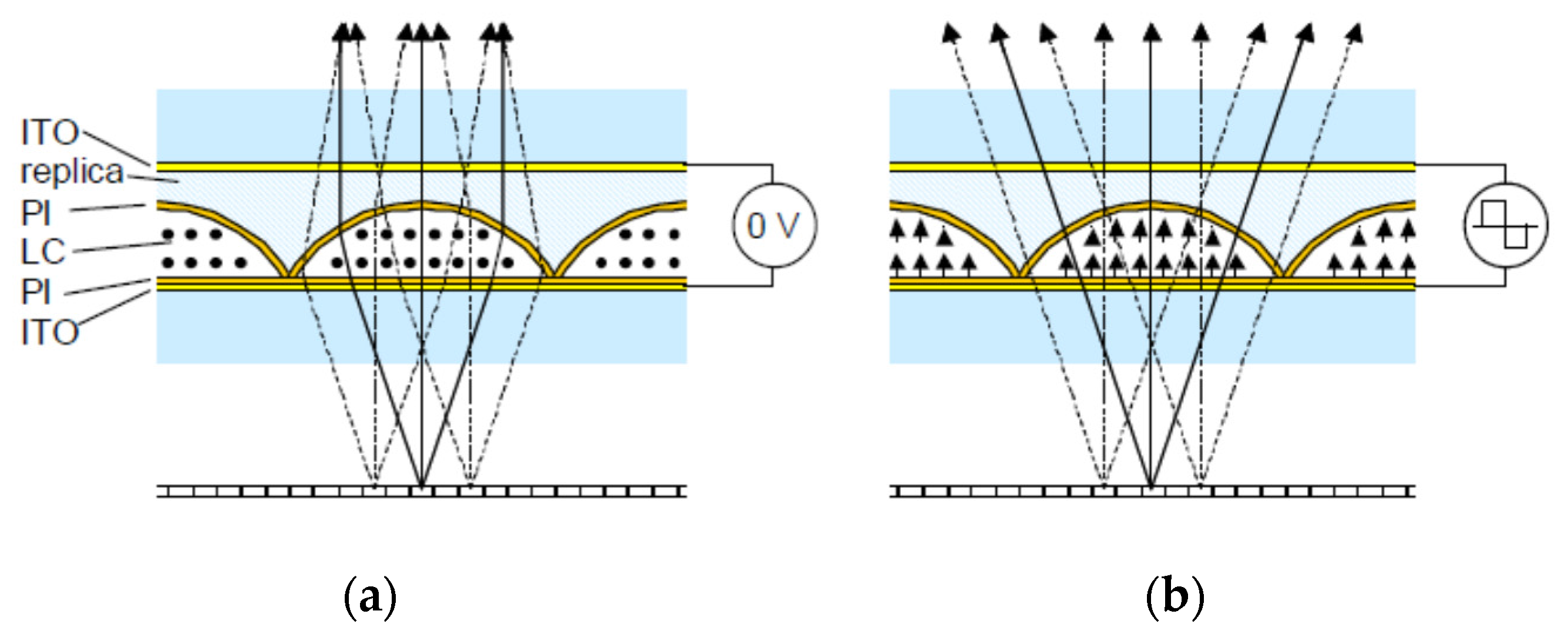
- Active birefringent lenses: A typical structure is shown in Figure 8 [55]. The cavity formed by the photoresin is filled with LC. Unswitched, a polarized light is affected by the extraordinary refractive index, greater than that of the photoresin (a positive lens is formed). When the LC is switched by an external electrical field, the polarized light is affected by the ordinary refractive index, similar to that of the photoresin (the light passes through without deviation). The main disadvantage is the high operating voltage (50–100 V).
Figure 8. Active birefringent lens: (a) without voltage and (b) with voltage [55]. Reprinted with permission from Willemsen, O.H.; de Zwart, S.T.; IJzerman, W.L.; Hiddink, M.G.H.; Dekker, T. International Society for Optics and Photonics; published by SPIE, 2006.Figure 8. Active birefringent lens: (a) without voltage and (b) with voltage [55]. Reprinted with permission from Willemsen, O.H.; de Zwart, S.T.; IJzerman, W.L.; Hiddink, M.G.H.; Dekker, T. International Society for Optics and Photonics; published by SPIE, 2006.![]()
- ➢
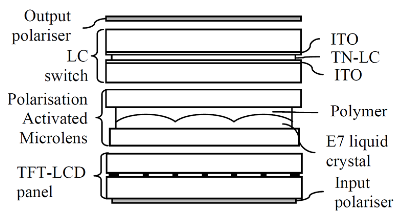
- Polarization Activated Microlenses: In this structure, two LC layers are used (Figure 9) [22]. One layer acts as the lens (nematic LC) and the other control the polarization by a twisted nematic (TN) LC. The TN LC cell change the polarization of the incoming light so it is affected by the extraordinary or ordinary refractive index of the nematic LC layer. This reduces considerably the operating voltage (only the TN cell is switched) but complicates the fabrication process. This type of lens only switches between focusing and non-focusing states, rather than tuning in a continuous focusing range like other LC lenses. For this reason, this structure has been proposed to work in a switchable 2D/3D mobile phone display [56]. Another option is to create polymeric lenses and use a similar structure [57]. The advantages are the switching speed and a reduction in crosstalk.
3.2. Patterned Electrode

3.3. Modal Control
3.4. Fabrication Methods of Liquid Crystal Microlenses for Autostereoscopic Applications
| Type | Topology | Fabrication Process | Voltage 3D | Switching Speed | Polarized Light |
|---|---|---|---|---|---|
| Curved Surface | Curved ITO | Sputtered ITO | 40–140 VRMS | ~1 s | Yes |
| Curved Glass | Immersed polymer microlenses | 10–20 VRMS | ~2 s | Yes | |
| Curved Photoresin Active | Complex fabrication process, several layers and TN LC in active cells | Depend on the topology | Several seconds | Yes | |
| Curved Photoresin Passive | 3.3 VRMS | <100 ms | Yes | ||
| Patterned Electrode | Hole patterned | Simple holes patterned | 2–3 VRMS | Several seconds | Yes |
| Bi-axial confocal | Special alignment layers | 3–10 VRMS | Unknown | No | |
| Blue-Phase | The blue-phase has to be synthetized | 50–100 VRMS | Several µs | No | |
| MeD-LC | Multiple electrodes | 5–10 VRMS | <100 ms | Yes | |
| Rotary cylindrical | Orthogonal electrodes | 2–3 VRMS | Several seconds | Yes | |
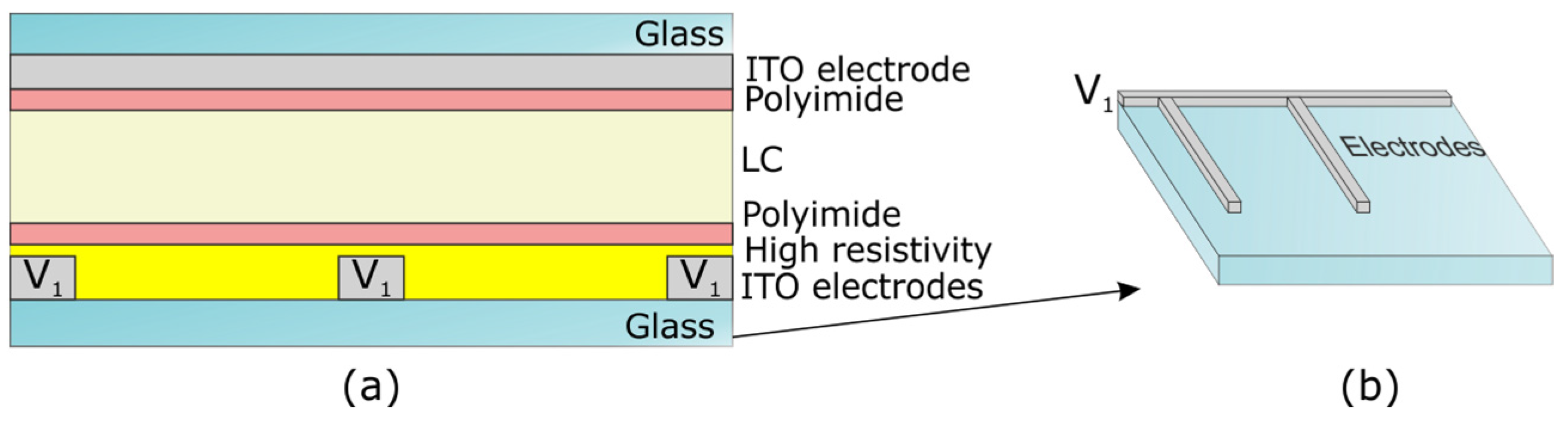
| Modal control | Hi-R LC | Difficult to obtain the high resistivity layer | ~2 VRMS | ~0.6 s | Yes |
| Cylindrical microlenses | ~7.5 VRMS | Several seconds | Yes |
4. Concluding Remarks and the Future of Autostereoscopic Displays
- The observer usually has the device in his own hands, so the 3D distance is considerably lower than with big displays. This requires a high optical power.
- Every observer has different physical characteristics, so tunability of this distance is especially required for a useful device.
- Aberrations of the optical elements used in this type of systems are a problem that has to be solved in order to reduce the crosstalk.
- The ability to display vertical, as well as horizontal, views is an added value of autostereoscopic displays.
Acknowledgments
Author Contributions
Conflicts of Interest
References
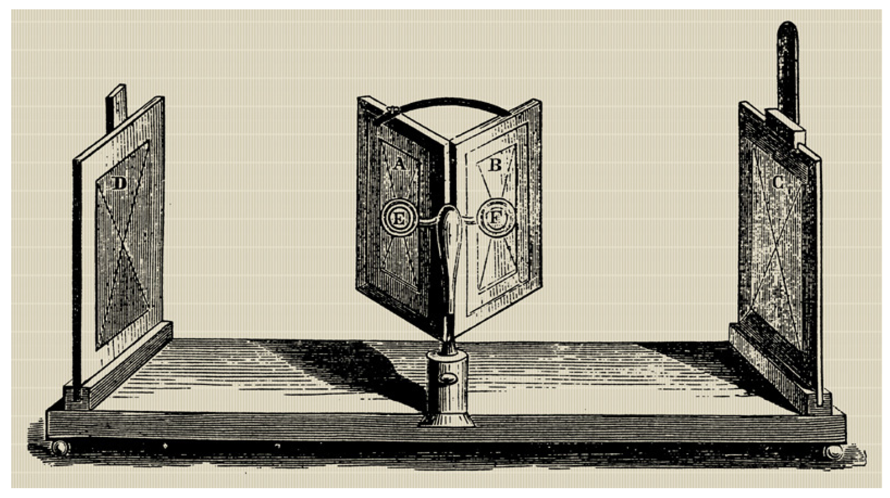
- Wheatstone, C. Contributions to the Physiology of Vision.—Part the First. On Some Remarkable, and Hitherto Unobserved, Phenomena of Binocular Vision. Philos. Trans. R. Soc. Lond. 1838, 128, 371–394. [Google Scholar] [CrossRef]
- Rollmann, W. Notiz zur Stereoskopie. Ann. Phys. 1853, 165, 350–351. [Google Scholar] [CrossRef]
- Ives, F.E. Parallax stereogram and process of making same. U.S. Patent 725,567, 14 April 1903. [Google Scholar]
- Lippmann, G. Epreuves reversibles donnant la sensation du relief. J. Phys. Appl. 1908, 7, 821–825. [Google Scholar] [CrossRef]
- Ives, H.E. Parallax panoramagram made with a large diameter lens. J. Opt. Soc. Amer. 1930, 20, 332–342. [Google Scholar] [CrossRef]
- Gibson, S. Stereoscopic apparatus and method of using same. U.S. Patent 4,295,153, 13 October 1981. [Google Scholar]
- Yaras, F.; Kang, H.; Onural, L. State of the Art in Holographic Displays: A Survey. J. Disp. Technol. 2010, 6, 443–454. [Google Scholar] [CrossRef]
- Slinger, C.; Cameron, C.; Stanley, M. Computer-generated holography as a generic display technology. Computer 2005, 8, 46–53. [Google Scholar] [CrossRef]
- Langhans, K.; Bahr, D.; Bezecny, D.; Homann, D. FELIX 3D display: An interactive tool for volumetric imaging. Proc. SPIE 2002, 4660. [Google Scholar] [CrossRef]
- Cossairt, O.; Travis, A.R.L.; Moller, C.; Benton, S.A. Novel view sequential display based on DMD technology. Proc. SPIE 2004, 5291. [Google Scholar] [CrossRef]
- Chien, K.-W.; Shieh, H.-P.D. Time-multiplexed three-dimensional displays based on directional backlights with fast-switching liquid-crystal displays. Appl. Opt. 2006, 45, 3106–3110. [Google Scholar] [CrossRef] [PubMed]
- Liang, H.; An, S.; Wang, J.; Zhou, Y.; Fan, H.; Krebs, P.; Zhou, J. Optimizing Time-Multiplexing Auto-Stereoscopic Displays With a Genetic Algorithm. J. Disp. Technol. 2014, 10, 695–699. [Google Scholar] [CrossRef]
- Chen, C.-H.; Yeh, Y.-C.; Shieh, H.-P.D. 3-D Mobile Display Based on Moiré-Free Dual Directional Backlight and Driving Scheme for Image Crosstalk Reduction. J. Disp. Technol. 2008, 4, 92–96. [Google Scholar] [CrossRef]
- Shestak, S.; Kim, D. Application of Pi-cells in time-multiplexed stereoscopic and autostereoscopic displays based on LCD panels. Proc. SPIE 2007, 6490. [Google Scholar] [CrossRef]
- Travis, A.R. Autostereoscopic 3-D display. Appl. Opt. 1990, 29, 4341–4342. [Google Scholar] [CrossRef] [PubMed]
- Mather, J. 3D TV Without glasses. Phys. World 2011, 24, 33–36. [Google Scholar] [CrossRef]
- Urey, H.; Chellappan, K.V.; Erden, E.; Surman, P. State of the Art in Stereoscopic and Autostereoscopic Displays. Proc. IEEE 2011, 99, 540–555. [Google Scholar] [CrossRef]
- Dodgson, N.A. Optical devices: 3D without the glasses. Nature 2013, 495, 316–317. [Google Scholar] [CrossRef] [PubMed]
- Xiao, X.; Javidi, B.; Martinez-Corral, M.; Stern, A. Advances in three-dimensional integral imaging: Sensing, display, and applications [Invited]. Appl. Opt. 2013, 52, 546–560. [Google Scholar] [CrossRef] [PubMed]
- Benzie, P.; Watson, J.; Surman, P.; Rakkolainen, I.; Hopf, K.; Urey, H.; Sainov, V.; von Kopylow, C. A Survey of 3DTV Displays: Techniques and Technologies. IEEE Trans. Circuits Syst. Video Technol. 2007, 17, 1647–1658. [Google Scholar] [CrossRef]
- Yamamoto, H.; Kouno, M.; Muguruma, S.; Hayasaki, Y.; Nagai, Y.; Shimizu, Y.; Nishida, N. Enlargement of viewing area of stereoscopic full-color LED display by use of a parallax barrier. Appl. Opt. 2002, 41, 6907–6919. [Google Scholar] [CrossRef] [PubMed]
- De Boer, D.K.G.; Hiddink, M.G.H.; Sluijter, M.; Willemsen, O.H.; de Zwart, S.T. Switchable lenticular based 2D/3D displays. Proc. SPIE 2007, 6490. [Google Scholar] [CrossRef]
- Peterka, T.; Kooima, R.L.; Sandin, D.J.; Johnson, A.; Leigh, J.; DeFanti, T.A. Advances in the Dynallax solid-state dynamic parallax barrier autostereoscopic visualization display system. IEEE Trans. Vis. Comput. Graph. 2008, 14, 487–499. [Google Scholar] [CrossRef] [PubMed]
- De Zwart, S.T.; Siebe, T.; Hiddink Martin, G.H. Autostereoscopic image output device. U.S. Patent 20,110,001,803, 6 February 2009. [Google Scholar]
- Pezzaniti, J. Autostereoscopic 3-D display. U.S. Patent 20,070,014,023, 3 July 2006. [Google Scholar]
- Kooi, F.L.; Toet, A. Visual comfort of binocular and 3D displays. Displays 2004, 25, 99–108. [Google Scholar] [CrossRef]
- Algorri, J.F.; Urruchi del Pozo, V.; Sanchez-Pena, J.M.; Oton, J.M. An Autostereoscopic Device for Mobile Applications Based on a Liquid Crystal Microlens Array and an OLED Display. J. Disp. Technol. 2014, 10, 713–720. [Google Scholar] [CrossRef]
- Chen, H.-S.; Wang, Y.-J.; Chang, C.-M.; Lin, Y.-H. A Polarizer-Free Liquid Crystal Lens Exploiting an Embedded-Multilayered Structure. IEEE Photonics Technol. Lett. 2015, 27, 899–902. [Google Scholar] [CrossRef]
- Algorri, J.F.; Urruchi, V.; Bennis, N.; Sánchez-Pena, J.M.; Otón, J.M. Tunable liquid crystal cylindrical micro-optical array for aberration compensation. Opt. Express 2015, 23, 13899–13915. [Google Scholar] [CrossRef] [PubMed]
- Algorri, J.F.; Urruchi, V.; Bennis, N.; Sánchez-Pena, J.M. A novel high-sensitivity, low-power, liquid crystal temperature sensor. Sensors 2014, 14, 6571–6583. [Google Scholar] [CrossRef] [PubMed]
- Algorri, J.F.; Urruchi, V.; Bennis, N.; Sánchez-Pena, J.M. Liquid Crystal Temperature Sensor Based on a Micrometric Structure and a Metallic Nanometric Layer. IEEE Electron. Device Lett. 2014, 35, 666–668. [Google Scholar]
- Algorri, J.F.; Urruchi, V.; Bennis, N.; Sánchez-Pena, J.M. Using an Analytical Model to Design Liquid Crystal Microlenses. IEEE Photonics Technol. Lett. 2014, 26, 793–796. [Google Scholar] [CrossRef]
- Berreman, D.W. Variable-focus LC-lens system. U.S. Patent 4,190,330, 26 February 1980. [Google Scholar]
- Sato, S. Liquid-Crystal lens-cell with variable focal length. Jpn. J. Appl. Phys. 1979, 18, 1679–1684. [Google Scholar] [CrossRef]
- Kowel, S.T.; Cleverly, D. A Liquid Crystal Adaptive Lens. In Proceedings of the NASA Conference Held at Langley Research Center, Hampton, VA, USA, 18–19 August 1981; pp. 329–339.
- Cleverly, D.S. Creation of a Lens by Field Controlled Variation of the Index Of Refraction in a Liquid Crystal. Ph.D. Thesis, Syracuse University, New York, NY, USA, 1982. [Google Scholar]
- Riza, N.A.; Dejule, M.C. Three-terminal adaptive nematic liquid-crystal lens device. Opt. Lett. 1994, 19, 1013–1015. [Google Scholar] [CrossRef] [PubMed]
- Nose, T.; Sato, S. A liquid crystal microlens obtained with a non-uniform electric field. Liq. Cryst. 1989, 5, 1425–1433. [Google Scholar] [CrossRef]
- Nose, T.; Sato, S. Optical properties of a liquid crystal microlens. In Proceedings of the International Conference on Optoelectronic Science and Engineering, Beijing, China, 22–25 August 1990.
- Williams, G.; Powell, N.; Purvis, A.; Clark, M.G. Electrically controllable liquid crystal fresnel lens. Proc. SPIE 1989, 1168. [Google Scholar] [CrossRef]
- Ye, M.; Wang, B.; Uchida, M.; Yanase, S.; Takahashi, S.; Sato, S. Focus tuning by liquid crystal lens in imaging system. Appl. Opt. 2012, 51, 7630–7635. [Google Scholar] [CrossRef] [PubMed]
- Lin, Y.-H.; Chen, M.-S. A Pico Projection System With Electrically Tunable Optical Zoom Ratio Adopting Two Liquid Crystal Lenses. J. Disp. Technol. 2012, 8, 401–404. [Google Scholar] [CrossRef]
- Lin, H.-C.; Collings, N.; Chen, M.-S.; Lin, Y.-H. A holographic projection system with an electrically tuning and continuously adjustable optical zoom. Opt. Express 2012, 20, 27222–27229. [Google Scholar] [CrossRef] [PubMed]
- Tsou, Y.-S.; Chang, K.-H.; Lin, Y.-H. A droplet manipulation on a liquid crystal and polymer composite film as a concentrator and a sun tracker for a concentrating photovoltaic system. J. Appl. Phys. 2013, 113, 244504. [Google Scholar] [CrossRef]
- Hassanfiroozi, A.; Huang, Y.-P.; Javidi, B.; Shieh, H.-P.D. Hexagonal liquid crystal lens array for 3D endoscopy. Opt. Express 2015, 23, 971–981. [Google Scholar] [CrossRef] [PubMed]
- Asatryan, K.; Presnyakov, V.; Tork, A.; Zohrabyan, A.; Bagramyan, A.; Galstian, T. Optical lens with electrically variable focus using an optically hidden dielectric structure. Opt. Express 2010, 18, 13981–13992. [Google Scholar] [CrossRef] [PubMed]
- Blum, R.D.; Kokonaski, W. Electro-active opthalmic lens having an optical power blending region. U.S. Patent 20,110,037,946, 17 Feruary 2011. [Google Scholar]
- Lin, Y.-H.; Chen, H.-S. Electrically tunable-focusing and polarizer-free liquid crystal lenses for ophthalmic applications. Opt. Express 2013, 21, 9428–9436. [Google Scholar] [CrossRef] [PubMed]
- Patel, J.S.; Rastani, K. Electrically controlled polarization-independent liquid-crystal Fresnel lens arrays. Opt. Lett. 1991, 16, 532–534. [Google Scholar] [CrossRef] [PubMed]
- Ren, H.; Wu, S.-T. Adaptive liquid crystal lens with large focal length tunability. Opt. Express 2006, 14, 11292–11298. [Google Scholar] [CrossRef] [PubMed]
- Harrold, J.; Wilkes, D.J.; Woodgate, G.J. Switchable 2D/3D display–solid phase liquid crystal microlens array. In Proceedings of the 11th International Display Workshops, Niigata, Japan, 8–10 December 2004.
- Dai, H.T.; Liu, Y.J.; Sun, X.W.; Luo, D. A negative—positive tunable liquid-crystal microlens array by printing. Opt. Express 2009, 17, 4317–4323. [Google Scholar] [CrossRef] [PubMed]
- Wang, B.; Ye, M.; Sato, S. Lens of electrically controllable focal length made by a glass lens and liquid-crystal layers. Appl. Opt. 2004, 43, 3420–3425. [Google Scholar] [CrossRef] [PubMed]
- Commander, L.G.; Day, S.E.; Selviah, D.R. Variable focal length microlenses. Opt. Commun. 2000, 177, 157–170. [Google Scholar] [CrossRef]
- Willemsen, O.H.; de Zwart, S.T.; IJzerman, W.L.; Hiddink, M.G.H.; Dekker, T. 2D/3D switchable displays. Proc. SPIE 2006, 6135. [Google Scholar] [CrossRef]
- Flack, J.; Harrold, J.; Woodgate, G.J. A prototype 3D mobile phone equipped with a next-generation autostereoscopic display. Proc. SPIE 2007, 6490. [Google Scholar] [CrossRef]
- Zhu, R.; Xu, S.; Hong, Q.; Wu, S.-T.; Lee, C.; Yang, C.-M.; Lo, C.-C.; Lien, A. Polymeric-lens-embedded 2D/3D switchable display with dramatically reduced crosstalk. Appl. Opt. 2014, 53, 1388–1395. [Google Scholar] [CrossRef] [PubMed]
- Lin, Y.-H.; Ren, H.; Fan-Chiang, K.-H.; Choi, W.-K.; Gauza, S.; Zhu, X.; Wu, S.-T. Tunable-Focus Cylindrical Liquid Crystal Lenses. Jpn. J. Appl. Phys. 2005, 44, 243–244. [Google Scholar] [CrossRef]
- Ye, M.; Wang, B.; Sato, S. Liquid-crystal lens with a focal length that is variable in a wide range. Appl. Opt. 2004, 43, 6407–6412. [Google Scholar] [CrossRef] [PubMed]
- Kawamura, M.; Nakamura, K.; Sato, S. Liquid-crystal micro-lens array with two-divided and tetragonally hole-patterned electrodes. Opt. Express 2013, 21, 26520–26526. [Google Scholar] [CrossRef] [PubMed]
- Kawamura, M.; Goto, H. Liquid crystal lens with two divided and double circularly hole-patterned electrodes. In Proceedings of the 2010 International Symposium on Optomechatronic Technologies, Toronto, ON, Canada, 5–27 October 2010; pp. 1–5.
- Li, Y.; Wu, S.-T. Polarization independent adaptive microlens with a blue-phase liquid crystal. Opt. Express 2011, 19, 8045–8050. [Google Scholar] [CrossRef] [PubMed]
- Hsu, C.-J.; Liao, C.-H.; Chen, B.-L.; Chih, S.-Y.; Huang, C.-Y. Polarization-insensitive liquid crystal microlens array with dual focal modes. Opt. Express 2014, 22, 25925–25930. [Google Scholar] [CrossRef] [PubMed]
- Hsu, C.J.; Sheu, C.R. Using photopolymerization to achieve tunable liquid crystal lenses with coaxial bifocals. Opt. Express 2012, 20, 4738–4746. [Google Scholar] [CrossRef] [PubMed]
- Hsu, C.-J.; Chih, S.-Y.; Jhang, J.-J.; Liao, C.-H.; Huang, C.-Y. Coaxially bifocal liquid crystal lens with switchable optical aperture. Liq. Cryst. 2015, 1–7. [Google Scholar] [CrossRef]
- Zhao, X.; Liu, C.; Zhang, D.; Luo, Y. Tunable liquid crystal microlens array using hole patterned electrode structure with ultrathin glass slab. Appl. Opt. 2012, 51, 3024–3030. [Google Scholar] [PubMed]
- Huang, Y.-P.; Chen, C.-W.; Shen, T.-C.; Huang, J.-F. Autostereoscopic 3D display with scanning Multi-Electrode driven liquid crystal (MeD-LC) Lens. 3D Res. 2011, 1, 39–42. [Google Scholar] [CrossRef]
- Li, K.; Robertson, B.; Pivnenko, M.; Deng, Y.; Chu, D.; Zhou, J.; Yao, J. High quality micro liquid crystal phase lenses for full resolution image steering in auto-stereoscopic displays. Opt. Express 2014, 22, 21679–21689. [Google Scholar] [CrossRef] [PubMed]
- Urruchi Del Pozo, V.; Algorri Genaro, J.; Sánchez-Pena, J.; Geday, M.; Arregui, X.; Bennis, N. Lenticular arrays based on liquid crystals. Opto-Electronics Rev. 2012, 20, 260–266. [Google Scholar] [CrossRef]
- Algorri, J.F.; Urruchi, V.; Bennis, N.; Sánchez-Pena, J.M. Cylindrical liquid crystal microlens array with rotary axis and tunable capability. IEEE Electron. Device Lett. 2015, 36, 582–584. [Google Scholar] [CrossRef]
- Urruchi, V.; Algorri, J.F.; Marcos, C.; Sánchez-Pena, J.M. Note: Electrical modeling and characterization of voltage gradient in liquid crystal microlenses. Rev. Sci. Instrum. 2013, 84, 116105. [Google Scholar] [CrossRef] [PubMed]
- Abramochkin, E.G.; Vasiliev, A.A.; Vashurin, P.V.; Zhmurova, L.I.; Ignatov, V.A.; Naumov, A.F. Controlled liquid crystal lens. Prepr. PN Lebedev Phys. Inst. 1988, 194, 18. [Google Scholar]
- Love, G.D.; Naumov, A.F. Modal liquid crystal lenses. Liq. Cryst. Today 2000, 10, 1–4. [Google Scholar] [CrossRef]
- Fraval, N.; de La Tocnaye, J.L.D.B. Low aberrations symmetrical adaptive modal liquid crystal lens with short focal lengths. Appl. Opt. 2010, 49, 2778–2783. [Google Scholar] [CrossRef] [PubMed]
- Loktev, M.Y.; Belopukhov, V.N.; Vladimirov, F.L.; Vdovin, G.V.; Love, G.D.; Naumov, A.F. Wave front control systems based on modal liquid crystal lenses. Rev. Sci. Instrum. 2000, 71, 3290–3297. [Google Scholar] [CrossRef]
- Kirby, A.K.; Hands, P.J.; Love, G.D. Liquid crystal multi-mode lenses and axicons based on electronic phase shift control. Opt. Express 2007, 15, 13496–13501. [Google Scholar] [CrossRef] [PubMed]
- Naumov, A.F.; Love, G.D.; Loktev, M.Y.; Vladimirov, F.L. Control optimization of spherical modal liquid crystal lenses. Opt. Express 1999, 4, 344–352. [Google Scholar] [CrossRef] [PubMed]
- Hands, P.J.W.; Kirby, A.K. Adaptive modally addressed liquid crystal lenses. Proc. SPIE 2004, 5518. [Google Scholar] [CrossRef]
- Kotova, S.P.; Patlan, V.V.; Samagin, S.A.; Zayakin, O.A. Wavefront formation using modal liquid-crystal correctors. Phys. Wave Phenom. 2010, 18, 96–104. [Google Scholar] [CrossRef]
- Flexible Optical LC Lenses. Available online: http://www.okotech.com/lc (accessed on 6 January 2016).
- Chang, Y.-C.; Jen, T.-H.; Ting, C.-H.; Huang, Y.-P. High-resistance liquid-crystal lens array for rotatable 2D/3D autostereoscopic display. Opt. Express 2014, 22, 2714–2724. [Google Scholar] [CrossRef] [PubMed]
- Huang, Y.-P.; Chang, Y.-C.; Chen, C.-W.; Liao, L.-Y.; Shieh, P.-T.; Jen, T.-H.; Chen, T.-H. Adaptive Liquid Crystal Lens(LC Lens) Array for 3D Display and Capturing. In Proceedings of the Digital Holography and Three-Dimensional Imaging 2012, Miami, FL, USA, 28 April–2 May 2012.
- Liu, Y.; Ren, H.; Xu, S.; Li, Y.; Wu, S.-T. Fast-response liquid-crystal lens for 3D displays. Proc. SPIE 2014, 9005. [Google Scholar] [CrossRef]
- Urruchi, V.; Algorri, J.F.; Sánchez-Pena, J.M.; Bennis, N.; Quintana, X.; Otón, J.M. Electrooptic characterization of tunable cylindrical liquid crystal lenses. Mol. Cryst. Liq. Cryst. 2012, 553, 211–219. [Google Scholar] [CrossRef]
- Khakifirooz, A.; Haji, S. UV-assisted nickel-induced crystallization of amorphous silicon. Thin Solid Films 2001, 383, 241–243. [Google Scholar] [CrossRef]
- Mohiddon, M.A.; Lakshun Naidu, K.; Ghanashyam Krishna, M.; Dalba, G.; Rocca, F. Growth, optical, and electrical properties of silicon films produced by the metal-induced crystallization process. J. Nanopart. Res. 2011, 13, 5999–6004. [Google Scholar] [CrossRef]
© 2016 by the authors; licensee MDPI, Basel, Switzerland. This article is an open access article distributed under the terms and conditions of the Creative Commons by Attribution (CC-BY) license (http://creativecommons.org/licenses/by/4.0/).
Share and Cite
Algorri, J.F.; Urruchi, V.; García-Cámara, B.; Sánchez-Pena, J.M. Liquid Crystal Microlenses for Autostereoscopic Displays. Materials 2016, 9, 36. https://doi.org/10.3390/ma9010036
Algorri JF, Urruchi V, García-Cámara B, Sánchez-Pena JM. Liquid Crystal Microlenses for Autostereoscopic Displays. Materials. 2016; 9(1):36. https://doi.org/10.3390/ma9010036
Chicago/Turabian StyleAlgorri, José Francisco, Virginia Urruchi, Braulio García-Cámara, and José M. Sánchez-Pena. 2016. "Liquid Crystal Microlenses for Autostereoscopic Displays" Materials 9, no. 1: 36. https://doi.org/10.3390/ma9010036
APA StyleAlgorri, J. F., Urruchi, V., García-Cámara, B., & Sánchez-Pena, J. M. (2016). Liquid Crystal Microlenses for Autostereoscopic Displays. Materials, 9(1), 36. https://doi.org/10.3390/ma9010036