2.1. Preparation of Nylon/Diamond Composites
The composite material was formulated utilizing PA66 as the polymeric matrix and diamond micro-abrasives (W14, Huifeng Diamond Co., Ltd., Zhecheng, China) as the superhard reinforcing phase, mixed at a mass ratio of 3:1 via dry physical blending. Diamond mass fractions exceeding 25 wt% induce severe particle agglomeration and an exponential surge in melt viscosity. This not only precipitates nozzle clogging during FGF extrusion but also severely disrupts the macromolecular continuity of the PA66 matrix, leading to embrittlement and a catastrophic loss of the required compliance. Conversely, abrasive loadings below 20 wt% fail to provide a sufficient density of active micro-cutting edges, resulting in a suboptimal material removal rate (MRR) against high-hardness P20 steel. Therefore, the 25 wt% diamond loading optimally maximizes cutting efficiency while preserving the intrinsic elasticity of the PA66 matrix, a prerequisite for activating the micro-yielding mechanism. High-frequency agitation utilizing a high-speed mixer was employed to facilitate preliminary dispersion and ensure homogeneous interfacial contact between the diamond particles and the PA66 matrix (Zhangjiagang Jushuo Machinery Co., Ltd., Zhangjiagang, China). Subsequently, melt extrusion and pelletization were executed using a twin-screw extruder, with the thermal processing window established between 220 °C and 260 °C, a range tailored to the specific plasticization kinetics of the constituents [
1]. Following rapid quenching and pellet cutting, PA66/diamond composite granules with a mean diameter of approximately 3 mm were successfully synthesized, conforming strictly to the feedstock dimensional requirements of subsequent desktop-scale FGF equipment [
2].
To accurately characterize the mechanical properties of the synthesized composite, the three-dimensional geometric design of the tensile specimens rigorously adhered to the ASTM D638 standard [
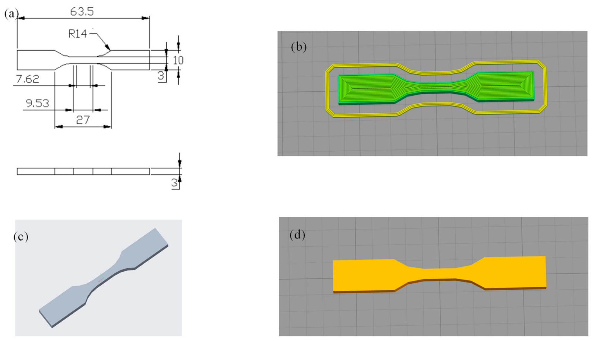
3]. Specifically, Type V specimens, featuring a uniform thickness and a narrow parallel-section width of 3 mm, were selected as the standardized test models over larger standard geometries to address specific thermal and rheological challenges during the FGF process. The smaller volume of Type V specimens significantly mitigates the severe thermal shrinkage and warpage inherent to semi-crystalline PA66, ensuring structural homogeneity. Additionally, the reduced printing duration minimizes nozzle wear and clogging risks associated with the prolonged extrusion of the highly viscous 25 wt% diamond-loaded melt. Geometric modeling was executed using Creo CAD (10.0) software, incorporating smooth fillet transitions at the gauge-to-grip interfaces to geometrically mitigate potential stress concentration phenomena (
Figure 1). Prior to additive manufacturing, the composite granules were subjected to continuous dehydration in an electro-thermal blast drying oven at 90 °C for 120 min. A drying temperature of 90 °C provides optimal thermal energy to expedite moisture diffusion without inducing premature thermal oxidative degradation. Concurrently, the 120 min duration guarantees comprehensive equilibrium dehydration throughout the entire granule volume. This pre-processing step was imperative to preclude moisture vaporization at elevated temperatures, which would otherwise induce hydrolytic degradation and porosity within the extruded matrix. This pre-processing step was imperative to preclude moisture vaporization at elevated temperatures, which would otherwise induce porosity within the extruded matrix. Specimen fabrication was conducted utilizing a CI Uni-Print D300 desktop 3D printer operating on the FGF principle (Zhejiang Challenge & Intelligence Technology Co., Ltd., Jinhua, China). The critical process parameters were empirically determined through preliminary single-factor printing trials aimed at balancing continuous extrusion stability with the ultimate mechanical integrity of the composite. To accommodate the pronounced melt viscosity induced by the 25 wt% diamond loading, the thermal parameters (screw plasticization and nozzle extrusion temperatures) were elevated to 250 °C, while the base deposition velocity was conservatively limited to 6 mm/s to preclude under-extrusion and nozzle clogging. Furthermore, to maximize inter-layer macromolecular diffusion and structural density, a layer height of 0.20 mm and a 100% triangular raster infill pattern were designated. Consequently, the finalized process parameters were established as follows: a bed temperature of 80 °C, screw and nozzle temperatures of 250 °C, and a deposition velocity of 6 mm/s. Post-fabrication, the specimen edges underwent manual deburring and finishing. Post-fabrication, the specimen edges underwent manual deburring and finishing. Dimensional fidelity was subsequently verified using vernier calipers. To ensure statistical reliability, critical dimensions (specifically, the parallel-section width and thickness) were measured at three distinct longitudinal locations along the gauge length for each of the six replicate specimens. This systematic multi-point evaluation (yielding a total of 18 measurements per critical dimension) confirmed that geometric deviations were strictly constrained within a tolerance of ±0.1 mm.
Tensile mechanical evaluations were executed utilizing a static universal testing machine (ZwickRoell, Ulm, Germany). To eliminate grip slippage and machine compliance errors, the true axial strain was directly captured via the extensometer with an initial gauge length (
) of 12 mm, rather than relying on crosshead displacement. Given the pronounced hygroscopic nature of the PA66 matrix and its susceptibility to moisture-induced plasticization, all tensile evaluations were rigorously conducted under controlled standard laboratory conditions, maintaining an ambient temperature of 23 ± 2 °C and a relative humidity of 50 ± 5%. To accommodate the distinct geometric profile of the Type V specimens and guarantee uniform stress distribution, parallel-jaw high-pressure grips were explicitly employed. During the experiments, the crosshead speed for axial tensile loading was rigidly maintained at a constant 5 mm/min. Given the inherent viscoelasticity of the PA66 matrix, a stable and relatively low strain rate of 5 mm/min is imperative. It effectively mitigates strain-rate-induced artificial stiffening, allowing sufficient relaxation time for the macromolecular chains. This ensures the accurate capture of the authentic yield point and the progressive micro-yielding behavior without triggering premature brittle fracture. To ensure statistical reliability, replicate testing was conducted across six standardized, as-fabricated specimens. The testing apparatus dynamically acquired load–displacement curves in real time, concurrently extracting critical mechanical parameters—specifically, maximum tensile load, ultimate tensile strength, elongation at break, and elastic modulus—as summarized in
Table 1.
As indicated in
Table 1, a noticeable dimensional variation was observed among the replicate specimens, exhibiting coefficients of variation (CV) of 7.35% for width and 7.47% for thickness. This geometric variance is an inherent characteristic of the desktop-scale FGF process when extruding highly filled semi-crystalline polymer melts. Specifically, the 25 wt% superhard diamond loading induces localized rheological fluctuations and irregular die swell during nozzle extrusion. Concurrently, the semi-crystalline PA66 matrix undergoes minor, anisotropic thermal shrinkage during the cooling phase. Furthermore, the necessary manual deburring process introduces slight geometric inconsistencies. Crucially, to rigorously preclude these structural variations from skewing the mechanical evaluation, the specific actual cross-sectional area of each individual specimen—derived from its precise multi-point measurements—was independently utilized to calculate the true engineering stress (UTS and yield strength), thereby ensuring the absolute fidelity of the reported mechanical properties.
2.2. Structural Design and Additive Manufacturing of the Elastic Polishing Head
To circumvent the severe geometric interference and residual tool marks characteristic of traditional rigid tools, a multi-layer composite elastic polishing head—integrating normal compliant buffering with highly efficient cutting micro-edges—was developed [
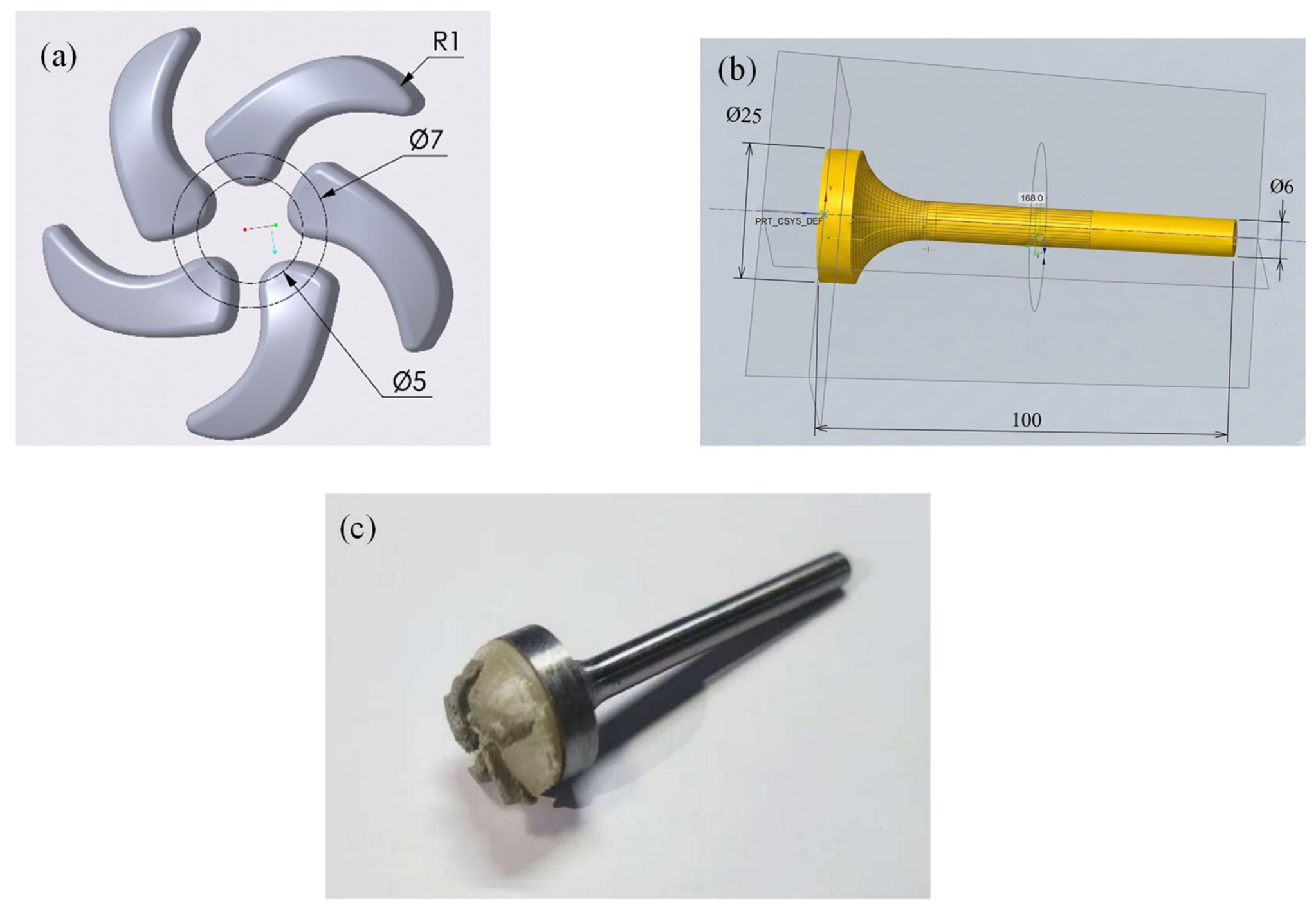
4]. Three-dimensional geometric modeling and structural design were executed utilizing Creo software (10.0). The elastic buffer layer, formulated from TPU, was architected as an inverted bowl structure (outer diameter: 20 mm; height: 5 mm) incorporating smooth R5 mm and R10 mm fillet transitions. This specific morphology is engineered to dynamically dampen high-frequency spindle vibrations and exert uniform normal contact pressure. The functional abrasive layer features a discontinuous five-petal configuration (thickness: 3 mm per petal), separated by engineered 2 mm radial gaps to facilitate chip evacuation [
5]. The rationale behind the discontinuous five-petal geometric configuration is fundamentally rooted in tribological optimization. Continuous polishing interfaces typically suffer from severe thermal damage and chip entrapment under heavy compressive loads. By engineering 2 mm radial gaps between the five petals, the functional abrasive layer facilitates efficient chip evacuation. This structurally discontinuous interface substantially mitigates frictional heat accumulation during high-speed rotation. More importantly, the gaps provide dedicated centrifugal flow channels for continuous flushing of metallic swarf and detached superhard diamond grains, thereby fundamentally precluding secondary rolling scratches on the highly reflective P20 mold steel surface. The geometric dimensions were derived from the target mold’s topography and the required mechanical compliance. The TPU layer’s 20 mm outer diameter prevents volumetric interference within restrictive mold corners. Its 5 mm height accommodates the 1.0 mm maximum
Z-axis penetration depth, limiting axial compressive strain to 20% to safely maintain hyperelasticity. Root fillets (R5 and R10) are incorporated to dissipate dynamic shear stress. For the active layer, a 3 mm petal thickness provides sufficient diamond abrasives for multi-pass cutting without compromising the composite tool’s macroscopic flexibility.
The rigid transmission shank was fabricated from premium AISI 1045 medium-carbon steel bar stock (initial dimensions: Ø25 mm × 100 mm). Computer numerical control (CNC) turning was employed to precision-machine the external diameter to 6 ± 0.02 mm and optimize the surface finish to a roughness of ≤0.8 µm. To augment the interfacial adhesion between the metallic shank and the polymeric TPU matrix, electrical discharge machining (EDM) was utilized to selectively ablate the 20 mm functional mating face. The EDM process was precisely controlled, employing a discharge current of approximately 8 A, a pulse-on time of 80 µs, and a pulse-off time of 160 µs, with a reference discharge area setting of 300 mm2. Profilometric measurements revealed an average surface roughness of 4.25 ± 0.35 µm on the processed shank. This specific micro-scale topography effectively functions as a mechanical anchoring network, significantly enhancing the interfacial adhesion strength and precluding structural delamination under dynamic shear forces during high-speed polishing operations. This process generated a highly porous, micro-cratered surface topography, which promotes robust mechanical interlocking upon adhesive infiltration. Subsequent meticulous degreasing was performed utilizing non-woven wipes saturated with medical-grade ethanol.
The selection of Fused Granulation Fabrication (FGF) over conventional machining or injection molding is driven by the need for geometric complexity and functional material integration. Subtractive machining of the PA66/diamond composite is impractical, as the superhard abrasives would induce severe tool wear. Conversely, injection molding this dual-layer structure (TPU core and PA66/diamond exterior) requires capital-intensive “two-shot” molds, making rapid iteration economically unviable. In contrast, dual-temperature-zone FGF enables the single-step, tool-less integration of these dissimilar layers. Furthermore, it allows the direct near-net-shape fabrication of the discontinuous five-petal geometry, completely bypassing traditional demolding constraints. Consequently, additive manufacturing is an essential, cost-effective enabler for realizing this functionally graded tool.
Additive manufacturing was executed via a “dual-temperature-zone” processing strategy utilizing FGF equipment. Initially, the TPU compliant layer was deposited using the following optimized thermal and kinematic parameters: a bed temperature of 80 °C, a nozzle temperature of 175 °C, a screw plasticization temperature of 170 °C, and a feed rate of 14 mm/s. The extrusion multiplier was strictly constrained to 28% to preclude excessive material overflow. Following the purging of residual TPU melt from the hopper and screw, the PA66/diamond composite granules were loaded for the fabrication of the functional abrasive layer. To ensure the precise geometric deposition of the highly viscous composite melt, the thermal parameters were elevated (nozzle: 250 °C; screw: 260 °C), while the kinematics were reduced to a feed rate of 6 mm/s and a volumetric flow rate of 0.2 mm3/s. The robust interfacial adhesion between the hyperelastic TPU buffer layer and the rigid PA66 abrasive layer is fundamentally governed by the thermo-mechanical dynamics of the dual-temperature-zone Fused Granular Fabrication (FGF) process. During continuous deposition, the high-temperature PA66 melt (extruded at 250 °C) induces localized thermal re-melting at the boundary of the previously deposited TPU substrate. This thermal activation facilitates trans-boundary macromolecular diffusion and chain entanglement between the two polymer matrices. Furthermore, the structural integrity was empirically validated during subsequent high-speed, heavy-load polishing operations, wherein the composite tool sustained continuous cyclic shear stresses without exhibiting any signs of interfacial delamination or mechanical decoupling.
Post-printing, the fabricated components underwent delicate manual finishing with fine-grit sandpaper and rigorous cleaning in absolute ethanol. The final precision assembly of the composite polishing tool (
Figure 2) was achieved by firmly bonding the base of the TPU layer to the EDM-roughened face of the steel shank. This was accomplished under constant holding pressure using a hybrid adhesion system comprising industrial-grade 3M double-sided tape and a high-strength two-part (AB) epoxy resin. Specifically, the epoxy resin components were homogeneously mixed at a 1:1 volume ratio. The adhesive was applied to the mating surfaces, which were then pressed firmly together to minimize the bond line thickness and maximize adhesive infiltration into the micro-cratered anchoring network. The assembly was subsequently subjected to a full room-temperature cure under constant holding pressure to guarantee maximum structural stability.
2.3. Experimental Design for Process Parameter Optimization and Adaptive Polishing Strategies on Complex Surfaces
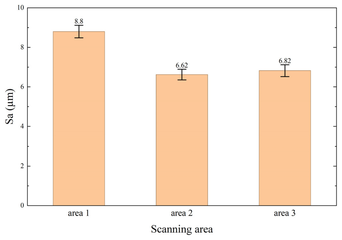
To elucidate the dynamic influence of machining parameters on mold surface roughness and to identify the optimal process window, comprehensive full-factorial and single-factor planar polishing experiments were systematically formulated. Machining trials were executed on a high-precision vertical machining center (V9, Gaoqi, Zhecheng, China). Standardized P20 mold steel workpieces, rough-milled to dimensions of 135 mm × 120 mm × 50 mm, served as the experimental substrates. To ensure the repeatability and consistency of the baseline material properties across all polishing trials, multiple replicate samples were systematically characterized. The initial condition of these specimens exhibited a characteristic rough-milled topography with dense mechanical tool marks. Crucially, macroscopic hardness testing was conducted across four distinct replicate samples, with four discrete indentations performed on each specimen. This systematic multi-point verification (totaling 16 measurements) confirmed a highly uniform and stable pre-hardened state, yielding an average macroscopic hardness of 33 ± 0.5 HRC. These planar specimens were explicitly utilized to establish a controlled, benchmarked testing framework prior to engaging complex freeform geometries. By conducting fundamental parameter optimization on these standardized flat substrates, the subsequent adaptive polishing results on deep cavities could be reliably compared against a stable planar baseline. Prior to processing, the specimens were subjected to rigorous degreasing protocols utilizing organic solvents to definitively eradicate residual cutting fluids and superficial oxide layers.
The experimental matrix evaluated four critical independent processing variables: depth of penetration, spindle speed, feed rate, and toolpath strategy. The penetration depth (Z-axis compression) was calibrated at 0.5 mm and 1.0 mm to assess the impact of the TPU layer’s compressive deformation—and the resultant normal contact pressure—on both material removal and “plastic smoothing” mechanisms. Spindle speed was varied across five discrete increments (500, 1000, 1500, 2000, and 2500 r/min) to characterize the thermomechanical response—specifically, the micro-rheological behavior and resulting surface topography—induced by varying linear cutting velocities and transient frictional heat. Furthermore, feed rates of 1.0, 2.0, 2.5, 5.0, and 10.0 mm/min were selected to investigate the geometric mapping of tool dwell time onto the efficiency of microscopic peak truncation. Toolpath planning compared “linear reciprocating” and “zig-zag” spatial interpolation trajectories to determine their influence on the homogeneity of the contact stress field. The cumulative planarization efficacy was also quantitatively evaluated across sequential unidirectional linear passes ranging from 1 to 5. The specific operational boundary conditions for the polishing parameters were rationally established based on the preliminary kinematic and thermo-mechanical constraints of the composite tool. The spindle speed range was selected to provide sufficient kinetic energy for continuous micro-cutting of the P20 mold steel, while the upper limit was strictly constrained to avert excessive frictional heat accumulation and the subsequent thermal degradation of the PA66 matrix. The boundaries for the Z-axis penetration depth were mathematically coupled with the compliance limits of the TPU buffer; the selected upper threshold prevents hyperelastic densification, thereby preserving the tool’s passive shape-adaptation capability. Concurrently, the horizontal feed rate range was optimized to balance manufacturing efficiency with an adequate trajectory overlap ratio, ensuring comprehensive spatial coverage without inducing localized thermal damage.
To rigorously quantify the statistical significance of the selected operational parameters on the final surface roughness, the experimental matrix was evaluated utilizing the principles of Analysis of Variance (ANOVA). The statistical evaluation confirms that the rotational spindle speed and the Z-axis penetration depth are the most dominant factors dictating the material removal rate and the dynamic contact mechanics. Specifically, an inadequate spindle speed fails to provide sufficient cutting velocity for the diamond abrasives, while excessive penetration depth induces severe hyperelastic densification of the TPU buffer, negating the passive compliance mechanism. Conversely, the horizontal feed rate exhibits a secondary, yet statistically significant, influence on the spatial homogenization of the polishing trajectories. This statistical hierarchy validates the optimized parameter combination utilized in the subsequent complex cavity trials. Based on these comprehensive analyses, the optimal polishing protocol was established as: a spindle speed of 2000 r/min, a feed rate of 1 mm/min, a penetration depth of 1 mm, executed via a linear reciprocating toolpath.
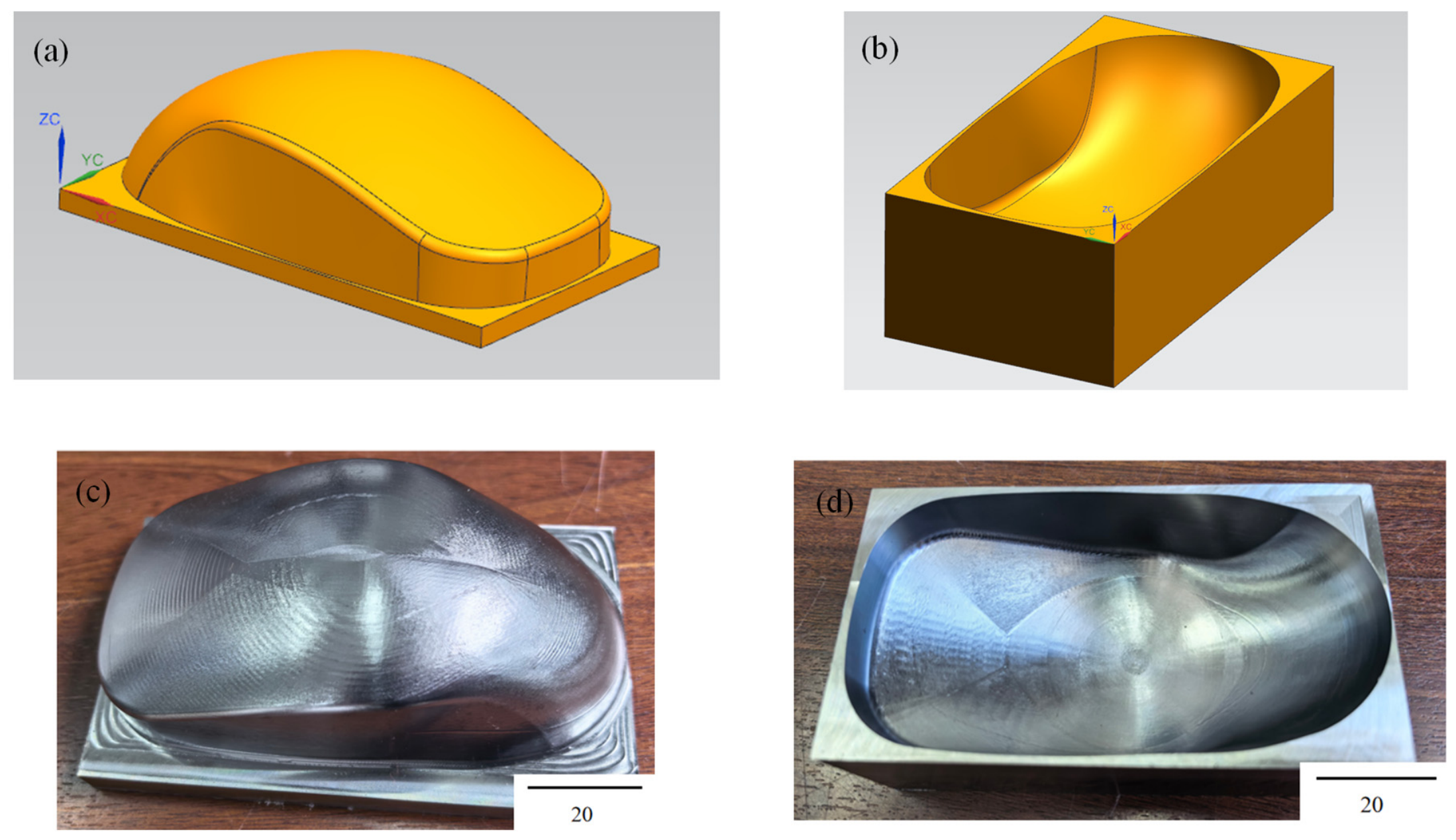
To address the critical issue of contact stress imbalance induced by dynamic variations in the normal vector during complex freeform surface machining, the passive compliance of the elastic tool was empirically validated on specimens featuring both convex and concave topographies. An authentic P20 steel mold cavity for a computer mouse, incorporating prominent convex profiles and deep concave features, was selected as the evaluation workpiece. The maximum envelope dimensions of the mold were 95.4 mm in length, 54.1 mm in width, and 30.5 mm in height (CAD modeling and physical prototypes are depicted in
Figure 3). Consistent with the planar trials, identical standardized degreasing and deoxidation pretreatments were rigorously applied prior to the adaptive polishing operations.
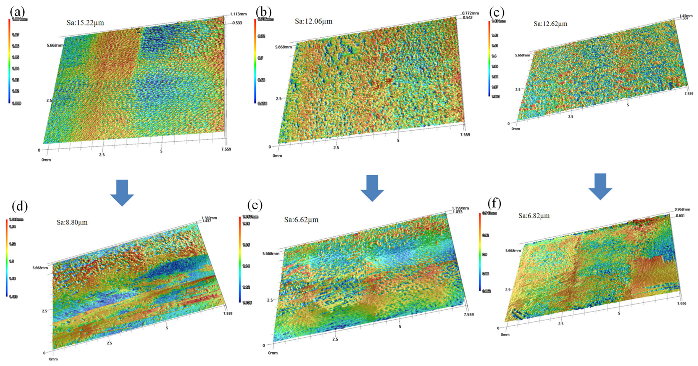
For the planarization of convex topographies, baseline trials were initially executed employing the optimal parameters established during the planar experiments. A fundamental kinematic limitation of standard three-axis machine tools is the inability of the Z-axis to dynamically align with the local surface normal, which inherently results in insufficient contact pressure across steep marginal zones. To rectify this deficiency, a “multi-pass, segmented regional polishing strategy” was introduced. Within the computer-aided manufacturing (CAM) programming, G-code trajectories were discretely partitioned for regions exhibiting steep normal vectors, and the local interpolation grids were consequently densified. This localized toolpath optimization effectively compensated for the machining non-uniformity induced by normal geometric interference.
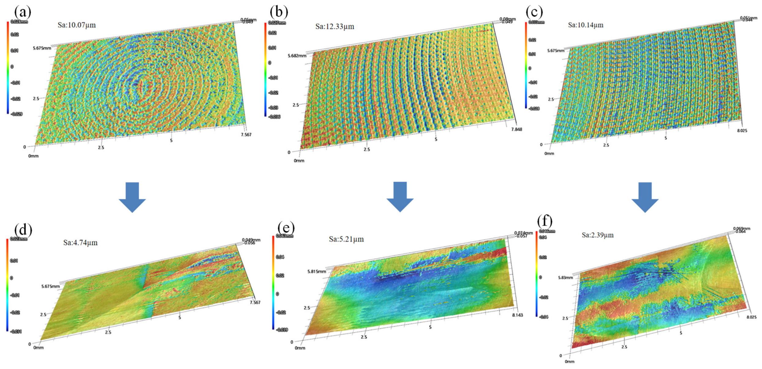
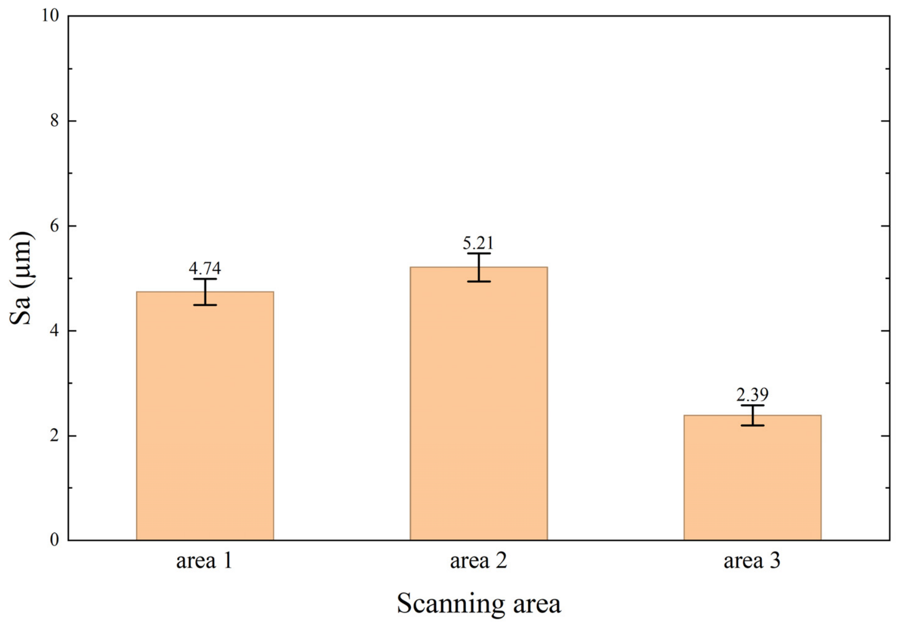
Conversely, polishing operations within deep concave cavities specifically focused on mitigating volumetric tool interference and the complex coupling of contact stresses along steep sidewalls. Methodologically, the CNC tool compensation paths were extensively optimized and trimmed. This strategy safely guided the elastic polishing head to avert rigid collisions with the sidewalls, while the engagement trajectories were precisely adjusted to guarantee comprehensive abrasive coverage within restrictive corner radii. To overcome the physical constraints of material removal intrinsic to confined deep-cavity environments, a high-intensity, five-pass sequential polishing regimen was implemented.
Upon completion of the respective polishing protocols for both the convex and concave features, 3D surface topographies and quantitative roughness metrics were comprehensively evaluated utilizing a 3D optical profilometer (VR-5000, Keyence, Osaka, Japan). The measurements were executed in high-magnification mode. To ensure the absolute fidelity of the extracted topographical features and avoid artificial data smoothing, both the S-filter and L-filter were intentionally disabled during the evaluation. A standard planar tilt correction was applied solely to level the measurement baseline. Strictly conforming to the ISO 25178 standard [
6] for areal surface texture measurement, the evaluation was conducted under standardized conditions to ensure data reliability and comparability.




 ,
,