Article

Influence of Specific Heat Input and Weld Configuration on Hardness and Residual Stress Distribution of S960MC Steel Welds


1
Faculty of Electrical Engineering and Information Technology, University of Zilina, Univerzitna 8215/1, 010 26 Zilina, Slovakia
2
Research Centre UNIZA, University of Zilina, Univerzitna 8215/1, 010 26 Zilina, Slovakia
3
CPIT—Centre for Advanced Innovation Technologies, VSB-TU Ostrava, 17. listopadu 2172/15, 708 00 Ostrava, Czech Republic
4
Faculty of Mechanical Engineering, University of Zilina, Univerzitna 8215/1, 010 26 Zilina, Slovakia
5
Institute of Physics of Materials, Czech Academy of Sciences, Zizkova 22, 616 00 Brno, Czech Republic
*
Author to whom correspondence should be addressed.
Materials 2026, 19(10), 2062; https://doi.org/10.3390/ma19102062
Submission received: 16 April 2026 / Revised: 6 May 2026 / Accepted: 8 May 2026 / Published: 14 May 2026

Abstract

This study investigates the influence of specific heat input and weld configuration on heat affected zone hardness and residual stress of S960MC high strength steel welds. In total, five types of weld samples were manufactured by Tungsten Inert Gas (TIG) autogenous welding and Metal Active Gas (MAG) butt welding to simulate the effect of increasing heat input and constraining the relative motion of welded parts during the heating and cooling phase. The obtained results show that the highest axial tensile residual stresses with magnitude above 900 MPa, combined with a hardness drop in a range from 13 up to 18%, occur mostly in the sub-critical heat affected zone, making it the critical zone of the weld. Increasing the heat input during welding does not have a simple correlation with generating more residual stresses and the trends obtained on the surface are different from results evaluated at a depth of 0.2 mm. Restraining the relative part motion during the welding affects mostly the tangential residual stresses, causing an increase in their tensile magnitude localized in the middle of the heat-affected zone while almost no influence on the axial residual stress component was recorded.

1. Introduction

High-strength low-alloy (HSLA) steels form an individual material group which gained significant importance in industry due to a favorable weight/strength ratio and high mechanical properties [1]. Their most significant advantage is that their unique mechanical properties are not achieved by increasing carbon content and rather by multiple strengthening mechanisms, such as grain refinement, dislocation strengthening, precipitation strengthening and phase transformation of austenite to martensite or bainite [2,3,4]. Thanks to the low content of alloying elements, these steels have a favorable carbon equivalent value and are suitable for welding with all conventional techniques [5,6,7].
On the other hand, as the applied strengthening mechanisms are naturally temperature unstable, welding of the HSLA steels has multiple specific negative aspects that need to be understood and considered in the welding process. The most challenging aspects of HSLA welding include susceptibility to cold cracking in the heat affected zone (HAZ) or weld metal (WM), softening in the HAZ and a significant decrease in toughness and ductility in the weld area. Due to the high temperature microstructure recovery processes, the most frequently observed negative aspect is a decrease in mechanical properties in the HAZ to a level below the mechanical properties of the material in as-received condition guaranteed by the manufacturer. These aspects have slowly unfolded thanks to multiple systematic studies performed in recent years such as those in references [8,9,10,11]. An important study was carried out by Amraei et al. [12], where the authors evaluated the microhardness of S960 HSLA steel samples heated to temperatures representing individual subzones of the HAZ and using of correlation equations between hardness and ultimate tensile strength (UTS) and determined theoretical strength. The results showed a 32% UTS drop when compared to the as-received material. In a second study by the same authors [13], it is concluded that the hardness drop in the HAZ of S960 steel can reach up to 46%. Generally, it is well understood that the key parameter influencing the negative aspects of HSLA welding is the size of specific heat input, and that the most critical sub-zone is the one heated below the Ac1 temperature. Heating causes recovery of the thermomechanically processed microstructure, mostly by decreasing the dislocation density accompanied by releasing the strain hardening [8,14,15].
One of the HSLA welding aspects still not fully understood is generation and distribution of residual stresses, which are created primarily due to thermal expansion and shrinkage of the melted and heated material and secondarily due to the phase transformations from the liquid to solid state and within the solid state (polymorphic metals) [6,16]. This aspect gains increasing importance as it was recently proven by Tichon et al. [17] that residual stresses are often the determining factor for fatigue crack propagation and might be more important than microstructural variation. The magnitude and distribution of residual stresses generated by welding depend on several factors, while the most significant still appears to be the specific heat input. Among other relevant factors that can be considered, the used welding technique, welding sequence, pre-heating, post-heating, type of filler metal and the total weld’s length should also be considered [7,18,19,20,21]. Alipooramirabad et al. [22] compared the influence of used filler metal and different welding sequences on residual stresses of API 5L grade X70 steel multi layered welds. The results have shown that higher residual stresses are generated by the flux cored arc welding process compared to conventional shielded metal arc welding and modified short arc welding. The highest magnitude of residual stress was obtained in the weld metal, and in many cases, it exceeded the yield point of the base metal. The authors also conclude that significantly higher residual stress magnitudes were obtained in the longitudinal direction when compared to the transverse and normal direction. Interestingly, the results also provided the analysis of the residual stress profile along the thickness of the weld, while the highest magnitudes were observed near the surface and decreased towards the root of the weld. This was caused by the fact that the heat generated during deposition of the subsequent passes imparts a tempering effect on the previous passes. In another work, Alipooramirabad et al. [23] analyzed the influence of specific heat input on residual stresses of multi-sequence welds while the heat input was modulated via welding speed. When using higher welding speeds, the specific heat input was 7.7 kJ/cm, while at lower speeds the heat input reached value of 19.1 kJ/cm. The analysis showed that, unexpectedly, slightly lower residual stresses were obtained at higher heat inputs. This was most likely related to different cooling rates what led to different phase composition of the microstructure in the weld metal and HAZ. In addition, the higher heat input had a higher tempering effect on the previous passes. Schroepfer et al. [24] studied how the filler metal strength and heat input value influences the size of reaction forces created during the material shrinking and how it is related to the post-weld residual stresses of S960Q HSLA welds. The authors concluded that when using a low heat input, the high strength G89 filler metal leads to decreased stress levels compared to the lower strength filler metal G69 due to effects of phase transformation. Based on the results, it was stated that the heat input for over-matching filler materials must be lower than for lower strength steel grades to maintain optimized residual stress levels.
In general, residual stress generation in welded joints is a highly complex task, and published experimental results show high ambiguity and are often even contractionary. For instance, in the work of Guo et al. [25] an experimental analysis was performed on S700 steel showing peak axial tensile residual stress magnitudes in the middle of the HAZ and lacking any information about tangential stress. In contrast, in the work of Sisodia et al. [26], where residual stresses on S960 steel were analyzed, results show highest axial tensile residual stresses on the boundary between the WM and the HAZ, while in the tangential direction in the whole WM and HAZ, only compressive stresses were recorded. In addition, the majority of the related works [16,26,27,28,29,30,31] focus only on the near-surface residual stresses omitting the possible in-depth stress transformation due to the self-equilibrating nature of residual stresses and significant influence of the weld configuration (available degrees of freedom for relative motion of the welded components). Therefore, to provide more comprehensive information about the residual stress development in HSLA welds, this study focuses on systematic mapping of residual stresses in five different welds on the surface and at a depth of 0.2 mm, evaluating the influence of weld technology, component restraining and variations in the heat input. The evaluation was performed at the beginning of the weld, where the components are initially at room temperature, in the middle and at the end of the welded joint, where the components are hottest due to the generated heat from the electric arc.

2. Experimental Material and Preparation of the Weld Samples

The experimental analysis was performed on S960MC HSLA steel in the as-received condition and with chemical composition shown in Table 1. It is a thermomechanically processed steel used for welding and cold forming. The steel contains Nb, V and Ti microalloying elements to form precipitates, which tend to block the recrystallization processes to maintain ultra-fine-grained microstructure after thermomechanical processing. Mechanical properties of the used 4 mm thick sheet metal obtained by a conventional tensile test are provided in Table 2. Microstructure of the experimental material revealed by optical microscopy (Figure 1) contains bainite, tempered martensite, retained austenite and precipitates (carbides of Nb, V and Ti).
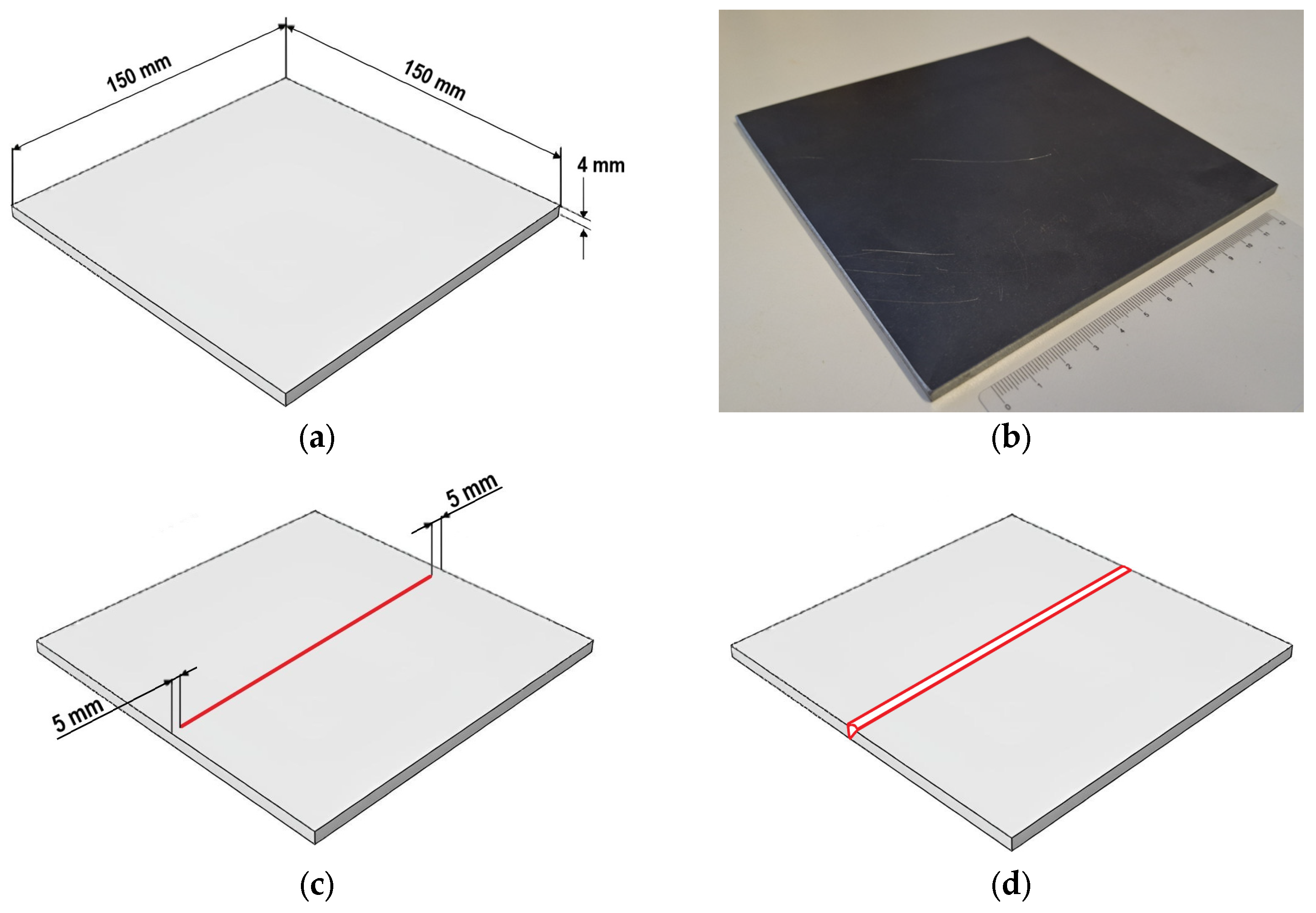
To manufacture the weld specimens, a 4 mm thick S960MC sheet metal was sectioned to dimensions of 150 × 150 mm, as shown in Figure 2a,b. For the first three samples (designated as Samples 1–3) a Tungsten Inert Gas (TIG) autogenous weld was performed in the middle of the sectioned sheet metal starting and ending 5 mm from the edge (Figure 2c). The process was essentially just remelting the material with use of a TIG welding torch to simulate a weld configuration, when the joined components are fixed together and unable to move freely during the heating and cooling. Additionally, on Sample 3 a root filling weld was simulated by re-melting of the material from the opposite side (bottom) of the sheet metal. The sheet metals for Samples 4 and 5 were sectioned in the middle to create a typical welding configuration, when the components are completely separated and can move freely during the welding. Afterwards, Sample 4 was TIG autogenously welded without use of filler metal. Sample 5 was welded by a conventional Metal Active Gas (MAG) welding process with use of G3Si1(G 42 4 C1/M21 3Si1, Voestalpine, Linz, Austria) wire filler metal (dia. 1 mm), as shown in Figure 2d. The welding process was always carried out at room temperature, and in the case of Sample 3, the material was fully cooled down prior to the secondary root filling.
To eliminate the influence of a human operator, all experimental samples were welded with use of automatic welding robot. The samples where the TIG method was used (Samples 1–4) were welded by FANUC LR Mate 200iD4S robot (FANUC, Oshino, Jamanasi, Japan). using Fronius MagicWave 2200 as the welding source. For the MAG weld of Sample 5 a KUKA VKR 250/2 robot (KUKA, Augsburg, Germany) was used with Fronius TPS 4000 CMT (Fronius, Wels, Austria) welding source. The full welding process parameters for all specimens are given in Table 3. The specific heat input Q was calculated by the following equation:
Q   =   U W × I W V W ×   η   [ J / cm ] ,
where UW is the welding voltage [V], IW is the welding electric current [A], VW is the welding speed [cm/s] and η is the heat transfer coefficient (for TIG η = 0.6 and for MAG/MIG η = 0.85).
The welding parameters for Sample 1 were experimentally obtained as the lowest heat input, which caused visible heating mark on the bottom of the sheet metal, proving that the material was thermally affected through the whole thickness. The heat input for Sample 2 was chosen as a 25% increase compared to Sample 1 to achieve a notable difference in the heat input and avoid unwanted microstructural changes and the creation of welding defects. Sample 3 was welded with the exact parameters as Sample 2, but additional remelting of the weld root was performed. For Sample 4, the welding parameters were kept very close to Sample 2 with minor modifications respecting the presence of a welding gap. The MAG weld parameters used for Sample 5 were chosen to achieve full weld penetration. The other related parameters of the thermal cycle for identical material with similar heat inputs was extensively studied in [9] and serve as a baseline for the following experimental analysis.

3. Experimental Analysis and Obtained Results

3.1. Residual Stress Analysis

3.1.1. Residual Stress Analysis Methodology

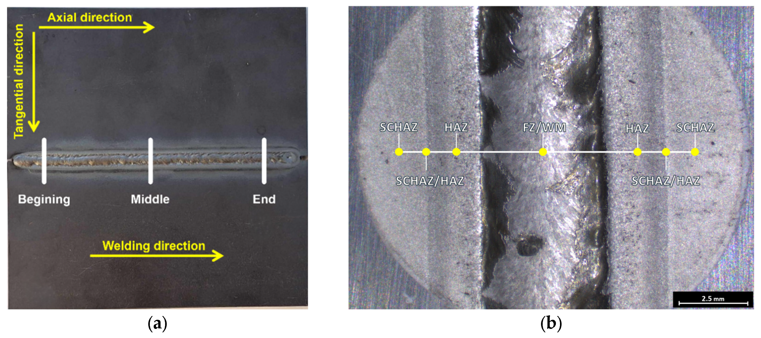
For residual stress evaluation, a sin2Ψ X-ray diffraction technique was applied. The used device was a Proto iXRD Combo with process parameters as follows: CrKα radiation, a total of seven tilt angles in the range of ±30°, and a Bragg angle of 156° (given by diffraction of {211} planes), with elastic constants for calculation of ferritic steel’s residual stresses: ½s2 = 5.75 TPa−1 and s1 = −1.25 TPa−1; irradiated area of 1 mm2. The measurement locations with respect to the heat affected subzones are designated in Figure 3.
The sin2Ψ X-ray technique is designed to evaluate the residual stress from several measurements performed in one location at different inclinations (tilt angles) and extrapolate the results to the desired φ–angle, which defines the stress orientation (e.g., axial, tangential). The advantage of this method is that each measurement provides statistics based on multiple measurements, together with a standard deviation value (plotted in all the residual stress graphs in Figure 4, Figure 5, Figure 6, Figure 7, Figure 8 and Figure 9 as error bars with values typically lying between 3 and 10% of the measured stress value). The irradiated area is defined by the diameter of the X-ray beam collimator, which is the factor determining the lateral resolution of the measurement technique. In this case, a collimator of 1.13 mm diameter was used, therefore to avoid overlapping of the irradiated area, the distance between adjacent measurement locations must be at least equal to the collimator diameter.
The residual stress analysis of the welded joints was performed on the top side of the weld by discrete line measurement in a direction perpendicular to the weld axis in the beginning, middle and end of the weld in axial and tangential directions, as depicted in Figure 3a. The bottom of the weld (root side) was not investigated. The surface oxide present on the sheet metal and on the weld had to be removed prior to the measurement by electro-chemical polishing to a depth of 0.03 mm to reveal the clean material surface. The polishing was performed with use of saturated water solution of NaCl as the electrolyte at 24 V and 2 A. After the removal, the HAZ was roughly visible and with respect to the lateral resolution, the line measurements were performed in seven locations, as shown in Figure 3b. After measuring the surface residual stresses, a second electropolishing was performed to reach a depth of 0.2 mm, and another set of residual stresses measurements was carried out. The reference value of residual stresses in the as-received material’s condition was measured on separate piece of sheet metal that was not subjected to any welding heat influence. It is also important to note that since in the TIG autogenous welds no filler metal is added (Samples 1–4), the weld mark will be referred as “Fusion Zone (FZ)” and in case of added filler material (Sample 5) it will be referred as “Weld Metal (WM)”. All the other HAZ subzones will be designated according to [9], as follows:
(a)
Coarse-Grained Heat Affected Zone (CGHAZ): characterized by significant grain coarsening due to heating significantly above the Ac3 temperature;
(b)
Fine-Grained Heat Affected Zone (FGHAZ): characterized by finer microstructure caused by heating to temperatures, which correspond to normalizing heat treatment;
(c)
Inter-Critical Heat Affected Zone (ICHAZ): a partially recrystallized zone, due to heating between the Ac1 and Ac3 temperatures, where only partial austenitization occurs;
(d)
Sub-Critical Heat Affected Zone (SCHAZ): area heated to temperatures lower than Ac1 corresponding to soft annealing.

3.1.2. Results of the Residual Stress Analysis

The reference residual stress values of the base metal are provided in Table 4, showing that the surface and in-depth axial residual stresses are both of low value and can be considered as near-zero. However, in the case of the tangential direction, the surface residual stress exhibits magnitude of −183 MPa, which changes to −93 MPa at a depth of 0.2 mm. Even when these values can be still considered low, they are not negligible as in the case of axial stress.
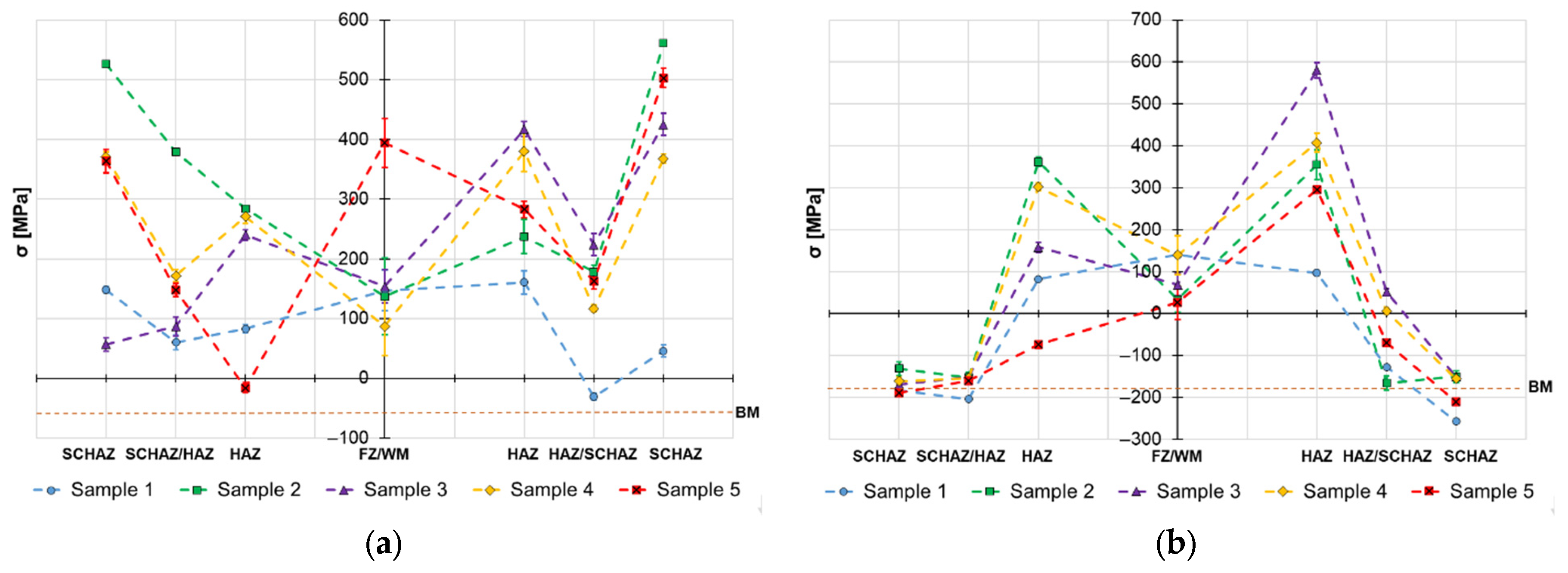
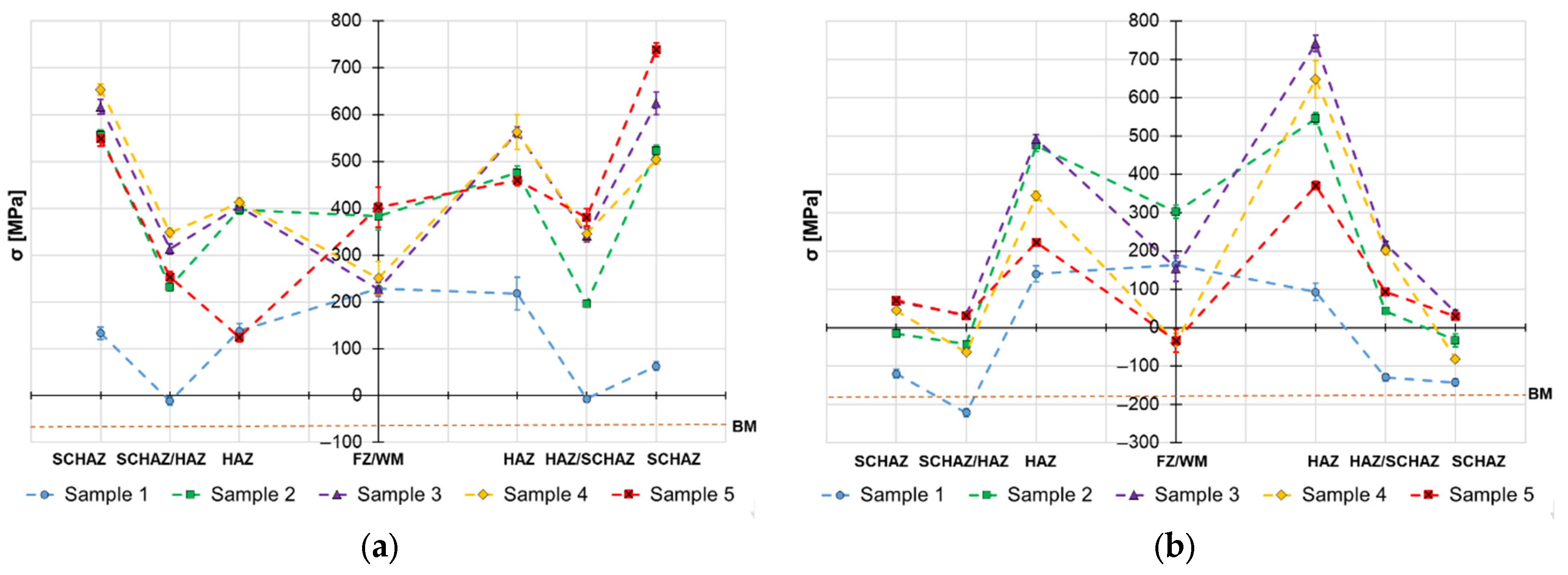
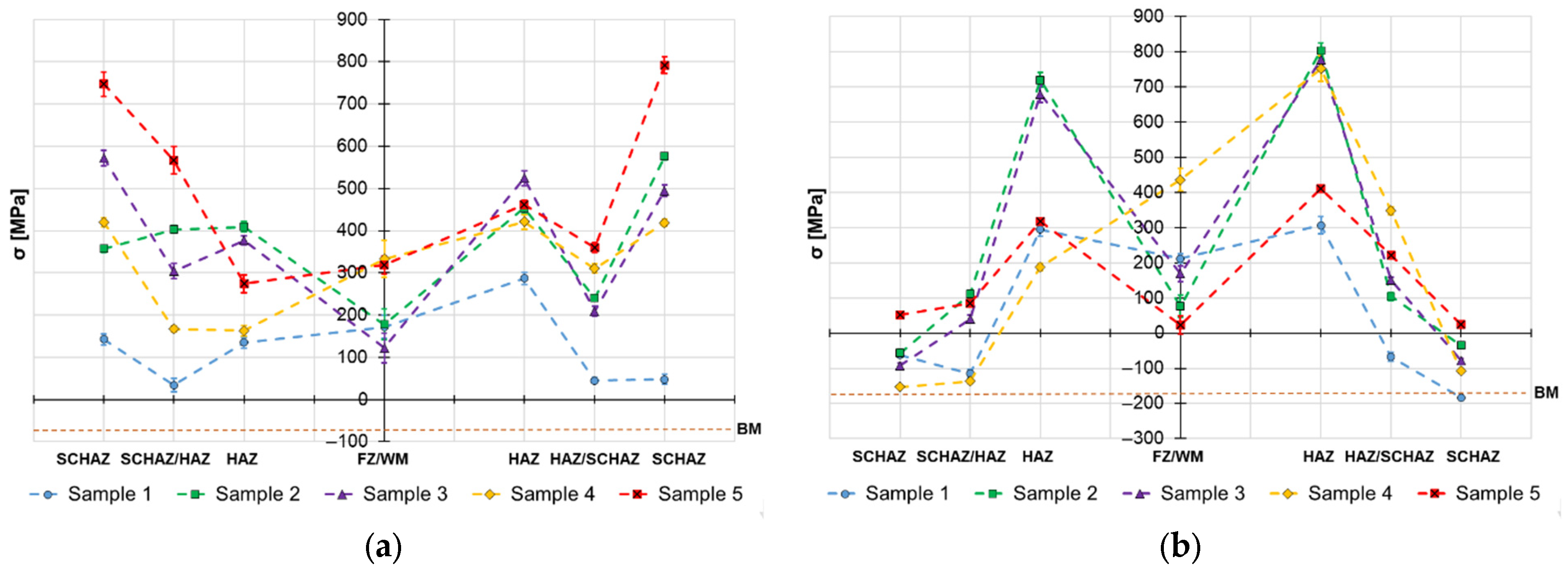
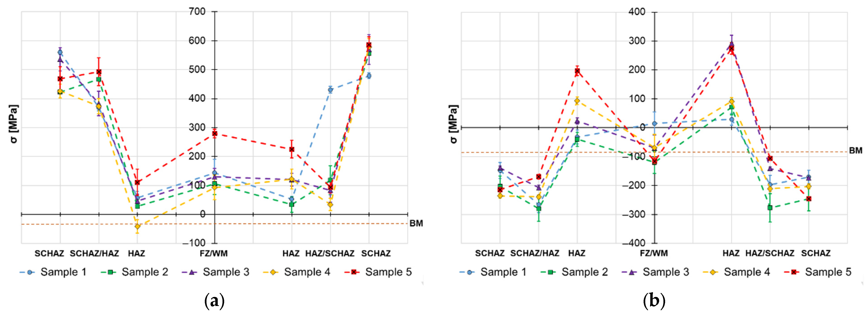
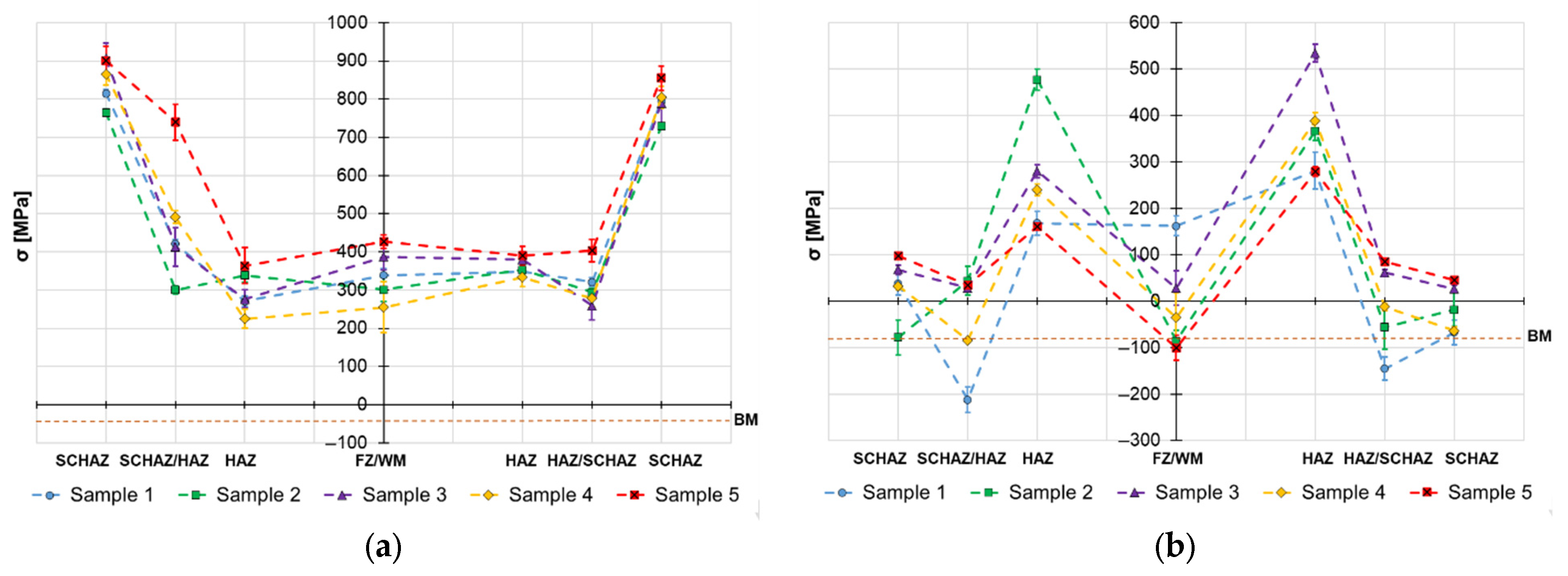
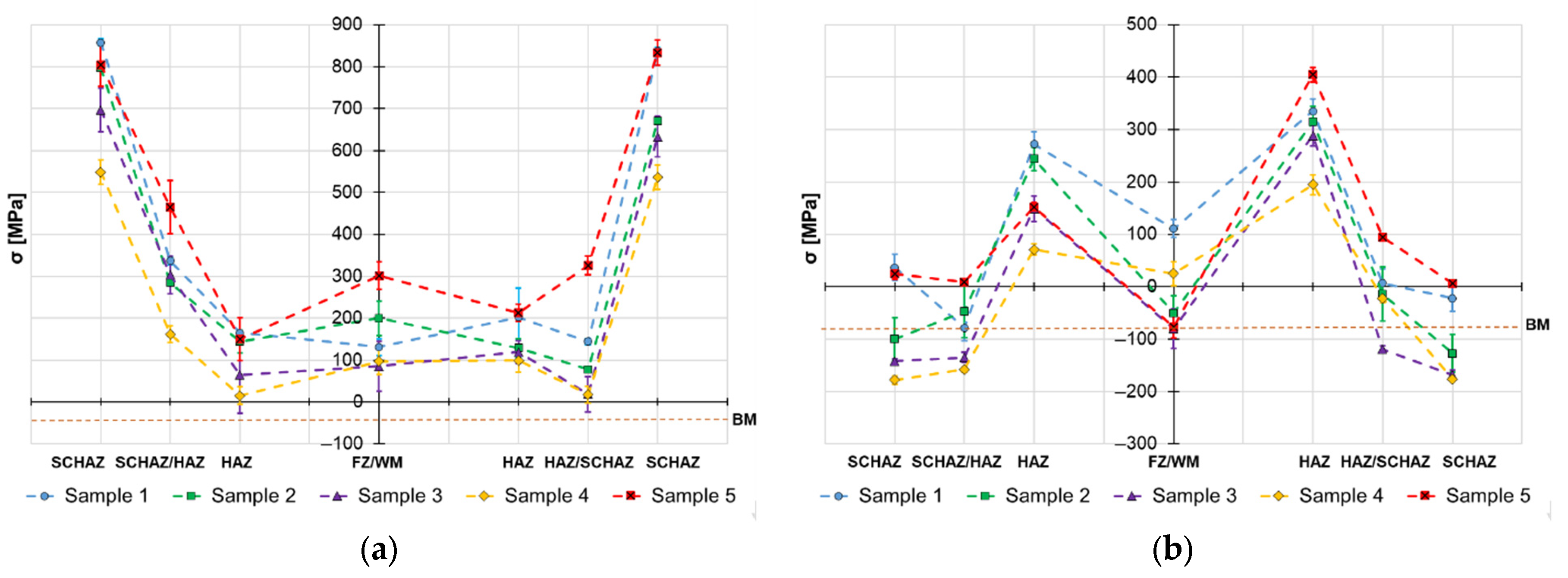
The obtained surface residual stress data are provided in Figure 4, Figure 5 and Figure 6 and the in-depth residual stresses are plotted in Figure 7, Figure 8 and Figure 9. All the originally measured residual stress values, which were used for the residual stress plots (Figure 4, Figure 5, Figure 6, Figure 7, Figure 8 and Figure 9), are provided in Appendix A. Generally, the highest axial tensile residual stresses in both surface and in-depth measurements were recorded in the SCHAZ zone (Figure 3b). The highest magnitude of an axial tensile residual stress value in the SCHAZ zone was reached in Sample 3 (906 MPa), followed by Sample 5, exhibiting a slightly lower magnitude of 901 MPa. Other than that, Sample 5 reached the highest axial residual stress values in almost every evaluated location, making it the sample with the highest overall residual stress content. In the tangential direction, for both surface and in-depth measurements, all samples exhibit highest value of residual stresses in the middle of the HAZ. The highest recorded value was for Sample 2 (804 MPa), followed by Sample 3 (777 MPa).
The residual stress evaluation position in the beginning, middle and end of the weld showed that generally the lowest residual stress values were obtained at the beginning of the weld, where the material is initially at room temperature. Residual stresses have a tendency to increase in the middle location, while the effect is more pronounced in the axial measurement direction in both surface and in-depth measurements. At the end of the weld, the obtained residual stress values are slightly lower than the ones measured at the middle, indicating possible influence of the measurement position near the edge of the material. However, this might be related just to the actual length of the welded samples (150 mm), and shorter or longer welds may behave differently.

3.2. Hardness Evaluation

3.2.1. Hardness Evaluation Methodology

To evaluate the mechanical properties of the weld’s subzones, a hardness measurement was performed using the HV0.5 method, following the guidance of the ISO 6507-1:2023 standard [32]. A line measurement of 60 indentation was carried out at a depth of 1 mm under the original surface, to be close to the location of the residual stress analysis, while still maintaining the required minimal distance from the surface required by the standard.

3.2.2. Results of the Hardness Evaluation

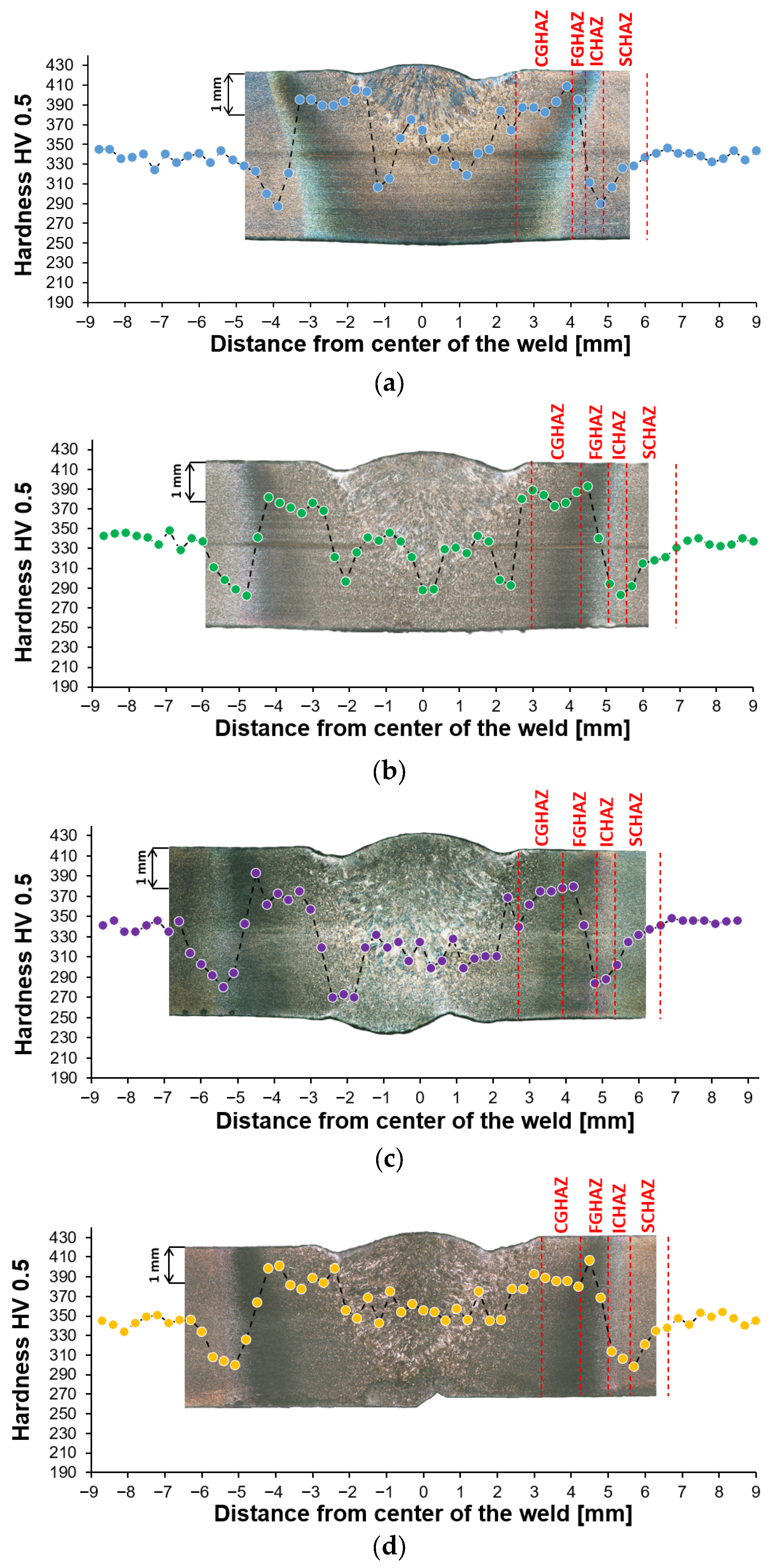
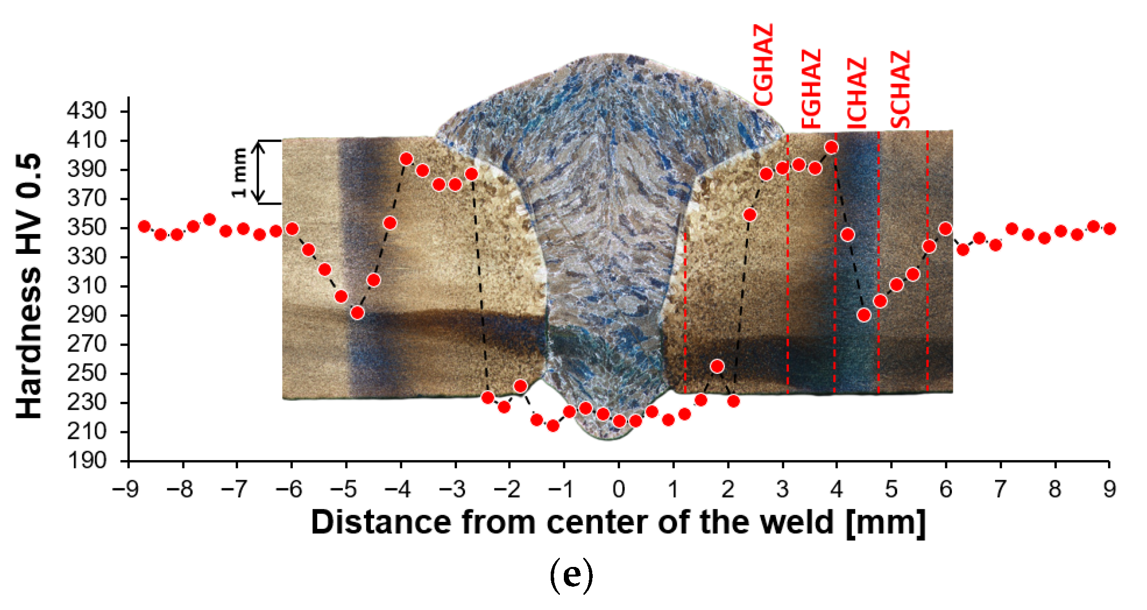
The microhardness traverse results for all samples are provided in Figure 10, and each measurement is paired with a metallography transversal macro-view for emphasizing the hardness values with respect to the individual subzones. The average hardness of the S960MC base metal in the as-received condition is approx. 340 HV0.5. In the case of the TIG autogenous welds (Samples 1–4), where no filler metal was added, the average hardness of the remelted material was very close to the hardness of the as-received material; however, the results are characterized by a high scatter (Figure 10a–d). In the weld toe, the hardness was approximately 40 HV0.5 higher with respect to the base metal. Further on, the lowest hardness values were recorded typically near the boundary between the ICHAZ or SCHAZ subzones of approximately 4 to 6 mm from the weld’s axis for all samples except Sample 3.
Sample 1 exhibited a decrease in hardness of the SCHAZ zone to approximately 290 HV0.5 (Figure 10a). Using a higher heat input for Sample 2 caused a decrease in the hardness for another 10 HV0.5 points to an approx. value of 280 HV0.5 (Figure 10b). A specific case was Sample 3, where the lowest hardness was observed in the location of −2 mm from the weld center in the CGHAZ zone (Figure 10c). This anomaly was most likely caused by the misalignment of the top and root weld, where the root welding caused secondary material annealing. In this location, the hardness decreased to a value of 270 HV0.5, which is slightly lower than the minimum obtained for the SCHAZ zone (280 HV0.5). Generally, the highest values of the hardness traverse were obtained in Sample 4, where the minimal hardness reached a value of 300 HV0.5 in the SCHAZ zone. Using the MAG welding process with addition of the G3Si1 filler metal for manufacturing, Sample 5 caused a significant hardness drop in the weld metal to approx. 220 HV0.5 (Figure 10d), while the CGHAZ reaches 290 HV0.5. This indicates a significant wire undermatch.
The hardness traverse measurements also provided a possibility to approximately estimate the width of the HAZ at the measurement depth of 1 mm. It is important to note that due to the welding process character, the HAZ is not ideally symmetrical, and the results are also related to the lateral resolution of the hardness measurement (indentation distances). The results provided in Table 5 (the heat input from Table 3 was added for reference) show that the width of the HAZ was increasing from Sample 1 up to Sample 3, correlating with the increased welding heat input. Sectioning the sheet metal plates for the welding of Sample 4 did not result in a change in the width of the HAZ as it is almost identical to Sample 2, which was welded with similar heat input. Sample 5 was welded with the use of additional filler metal and a heat input higher than Sample 2, and despite the higher heat input, the weld HAZ was narrower.

4. Discussion

The primary aim of the study was to observe the influence of heat cycle parameters and part fixation on residual stress generated in welds manufactured from S960MC steel by TIG and MAG methods. As can be seen from the results, the welded joints exhibit different trends in the axial and tangential directions. In the axial direction, preferably tensile residual stresses are created with a maximum in the SCHAZ zone, while in the tangential direction, compressive residual stresses are created in this zone, and maximal tensile residual stresses are in the middle of the HAZ. The magnitudes of the axial residual stresses in the HAZ reach values close to 80% of the yield point and can be considered severe, since the magnitudes are on the edge of becoming an elasto-plastic deformation. Typically, in works related to residual stresses of the S960 MC butt welds, the magnitudes in the axial direction reach values close to 650 MPa [26,33,34]. However, all these works were related to application of progressive welding technologies, such as electron beam or laser welding, which operate at much lower heat inputs (approx. 1 kJ/cm). In the case of TIG autogenous welding, the residual stresses with magnitudes close to 900 MPa were also obtained by Sun et al. [18], where S960MC steel with 8 mm sheet thickness was welded with heat input of 20 kJ/cm; therefore, such high values are not uncommon for this welding technology.
Based on the obtained axial residual stress results evaluated on the surface of the autogenously welded samples, Sample 1 (2.9 kJ/cm) and Sample 2 (3.6 kJ/cm), it appears that generally the magnitude of residual stress increases with increasing heat input when using identical weld configuration. The reason for this behavior lies primarily in softening of the SCHAZ zone. As this zone is softer than the adjacent high-strength region, the material yields, while the surrounding material is mostly elastic. The plastically shortened SCHAZ is later elastically “pulled back” by the stronger material as the joint equilibrates, leaving it in the axial tension [35]. The more heat that is introduced in the material, the higher the thermal expansion, causing generation of higher residual stresses. This is also related to the cumulative heat input (Table 3), which is an integration of the delivered heat to the material with respect to the welding length—changes in the residual stress profiles might vary when shorter or longer welding lengths are considered. However, when changes in the weld sequencing and configuration are introduced, as in the case of Samples 3, 4 and 5, the residual stress generation does not follow this simple relationship, due to additional factors, such as the secondary annealing of Sample 3 by root filling welding, removing of material constraining (Samples 4 and 5) or adding filler material (Sample 5).
The reason why in tangential direction the tensile residual stresses achieved the highest magnitude in the middle of the HAZ is related to the fact that during the welding the material in the hot zone (material volume with temperature above 450 °C) has restrained ability for relative motion by the cold zone (material with temperature below 450 °C, where the thermal expansion is negligible) [16]. This leads to transversal curvature along the weld causing tension in the weld’s middle. This generates high tensile residual stresses in the HAZ due to following thermal shrinking of the weld metal. Since a part of the thermal expansion was already accommodated by the hot material plastic flow, the subsequent restrained contraction leaves tensile residual stress to satisfy the overall equilibrium. This effect is even more pronounced when the welded components are also mechanically restricted from any possible tangential relative motion, as the restrictions add to the significance of the cold zone effect. The observation agrees with work of Park et al. [36] who conclude that fixation of the welded components has significant influence, mainly on the tangential residual stresses magnitude, while the axial stresses are not sensitive to this change.
Unalike the thermal expansion, the influence of volume change during the solid-state phase transformation is not present in the whole temperature interval, as it occurs between 700 and 900 °C. During this interval, the ferrite/austenite transformation adds (heating cycle) or subducts (cooling cycle) an additional ≈1% of volume difference [37]. However, as the phase transformation occurs in the material at high temperatures, when the yield point of the material is lower, the volume changes are mostly accommodated by the plastic flow of the hot zone. This contributes to the yielding caused by thermal expansion and compels reaction forces in the HAZ.
On the other hand, the in-dept residual stress measurements are not showing such a simple dependance between the residual stress magnitude and welding heat input. The in-depth axial residual stress magnitudes of Sample 1 are higher when compared to almost all the other tested samples, mainly in the middle and end measurement locations. In the tangential direction, the residual stress magnitudes of Sample 1 differ from the surface measurement. For this case, the stresses are not as low as they were on the surface and lay on a similar level to other evaluated welds with higher heat inputs. This emphasizes the complexity of the reaction forces created during the heating cycle and influence of the surface to core stress gradients. This implies that only surface residual stress evaluation does not provide sufficient information on the real residual stress state of the HSLA welds.
Similar behavior of the heat input influence on surface residual stresses was observed by Nitschke-Pagel and Wohlfahrt in [38]. In the study, they demonstrated experimental results of welded steel by a TIG method with use of 6 kJ/cm and 20 kJ/cm heat inputs. The obtained results indicated that the heat input influences not only the magnitude, but also the distribution of axial residual stress: low heat inputs generate more compressive residual stresses and high heat inputs support generation of tensile residual stresses. In addition to the residual stress profiles, the authors also recorded the cooling curves and plotted them against the corresponding continuous cooling transformation (CCT) diagram of the used steel. The results show that selection of a lower heat input led to a lower transformation temperature, which reduced the scope of contraction stresses generated after the transformation was exhausted. This was one of the main reasons for the change in the character of residual stress. On the other hand, work of Jiang et al. [21] concludes that higher heat input during the welding process does not necessarily mean higher residual stresses, mainly in the tangential direction, and can even cause their decrease. The authors claim that the reason for this behavior is related to an increase in the welding temperature due to an increase in the heat input. When the welding temperature increases, the deformation increases, causing release of more residual stress. Therefore, the transverse stress magnitudes are decreased. This would explain the decrease in residual stress on the surface of Sample 5, visible in Figure 4, Figure 5 and Figure 6, and the variation of tangential residual stresses in the other samples. The values of residual stress in Sample 5 might be also influenced by low hardness of the filler metal, which was able to accumulate more plastic deformation caused by the thermal dilatation.
The influence of the measurement location with respect to the beginning, middle and end of the welded joint showed a difference only for the axial residual stresses, which tend to be generally higher in the middle. This applies for both surface and in-depth results. Similar behavior was also observed in [26] and is most likely related to the fact that the material at the beginning and end is closer to the edges, which are less constrained in the ability of the elasto-plastic material flow, mainly in the axial direction. However, as this behavior was still not widely studied, confirmation by future analyses might be required, and the influence of the actual temperature of the welded components, which gradually changes due to the welding, also needs to be investigated.
Besides the highest magnitude of axial residual stresses, the SCHAZ zone is also characteristic by significant reduction of mechanical properties, which is recorded by the hardness drop. This area is often referred as a “soft zone”, and for the welds in this study, the hardness drop was in the range of 13% to 18%. According to work by Amraei et al. [12], the hardness drop in the soft zone in high strength steels can reach even 60%. According to [14,39], the SCHAZ zone represents a material volume heated below the Ac1 temperature (less than 550 °C), where no ferrite/austenite phase transformation is present. Therefore, the grain recovery and decrease in dislocation density are the primary mechanisms responsible for the hardness drop. This was also confirmed in [40], where TEM analysis revealed that the microstructure of this zone consists of a fine martensite and bainite mixture, meaning it is identical as in the base metal. Mičian et al. [9] analyzed the relation between welding parameters and softening in high strength steels welded by the MAG method. The results of the tensile tests showed that despite the welding parameters used, each specimen fractured in the SCHAZ sub-zone, identifying it as the most critical zone for quasi-static loading. This zone also appears to be the most sensitive to cyclic loading as lower hardness causes higher yielding of the material in this zone, creating a location for localization of a cyclic elasto-plastic deformation. However, since the residual stresses tend to add to the applied forces [41,42], in the case of fatigue loading in the tangential direction, the sum of the stresses may shift the location of the fatigue crack initiation to the HAZ.

5. Conclusions

The aim of the study was to analyze the influence of welding cycle parameters, heat input and weld configuration on residual stress distribution in S960MC steel welded joints. Based on the obtained experimental data and critical discussion, the followng can be concluded:
-
Using TIG and MAG welding technology can generate tensile residual stresses with magnitudes of 80% of the material’s yield point. The highest magnitudes present in the SCHAZ subzone are oriented in the axial direction—the direction of the welding. The SCHAZ subzone is also characterized by a significant drop caused by recovery processes in the material due to annealing at temperatures below the Ac1. The combination of these two factors is crucial for mechanical strength and fatigue resistance of the welded joint; however, the contribution of the axial residual stresses would be notable, mainly in the case of axial loading.
-
Restraining the relative motion of the welded components results in generating high magnitudes of tensile residual stresses in the tangential direction localized in the middle of the HAZ. Although, the HAZ is not characterized by significant softening, in the case of tangential loading, the residual stresses will contribute to the total loading and might cause a shift in the initial failure location.
-
With respect to the surface residual stresses, a direct relation between increasing heat input and residual stress magnitudes is observed. However, the in-depth residual stresses (measured at a depth of 0.2 mm) do not confirm this simple relationship. In the case of the lowest applied heat input for TIG autogenous welding, the surface residual stresses showed significantly lower values when compared to the in-depth measurements. This indicates that evaluating only surface residual stresses can provide false assumptions of the weld’s residual stress state.
-
Evaluation of surface residual stresses in the axial direction at the beginning of the weld shows the highest scatter among all the measured locations. However, such a notable scatter was not observed in either the tangential direction or in the in-depth measurements. With respect to the weld location, without few exceptions (e.g., Sample 2), the highest axial residual stresses were typically present in the middle, indicating a possible influence of the edge proximity and immediate material temperature. Nevertheless, the results are not conclusive and would require further investigation.

Author Contributions

M.M., L.T. and M.F., conceptualization and methodology; M.M. and M.F., investigation; F.N., funding acquisition and validation; L.T., writing—original draft preparation; and M.J. and V.M., writing—review and editing. All authors have read and agreed to the published version of the manuscript.

Funding

This research was financially supported by the Slovak Research and Development Agency under contract No. APVV-20-0427, by project VEGA no. 1/0831/25, by the European Union under the REFRESH—Research Excellence for Region Sustainability and High-tech Industries project number CZ.10.03.01/00/22_003/0000048 via the Operational Programme “Just Transition” and by the project No. CZ.02.1.01/0.0/0.0/17_048/0007373 “Damage Prediction of Structural Materials”, within the Research, Development and Education Operational Programme financed by the European Union and from the state budget of the Czech Republic.

Data Availability Statement

The data that supports the findings of this study are available on request from the corresponding author, L.T.

Conflicts of Interest

The authors declare that they have no known competing financial interests or personal relationships that could have appeared to influence the work reported in this paper.

Abbreviations

The following abbreviations are used in this manuscript:
TIGTungsten Inert Gas welding
MAGMetal Active Gas welding
HSLAhigh strength low alloy steels
QTquenching and tempering
TMCPthermo-mechanical control processing
HAZheat affected zone
WMweld metal
UTSUltimate Tensile Strength
FZFusion zone
CGHAZCoarse-Grained Heat-Affected Zone
FGHAZFine-Grained Heat Affected Zone
ICHAZInter-Critical Heat Affected Zone
SCHAZSub-Critical Heat Affected Zone
CCTcontinuous cooling transformation

Appendix A

Appendix A.1

Table A1. Welding residuals stresses–Sample 1, surface.
Axial Direction
LocationSCHAZStd.
dev.
SCHAZ/HAZStd.
dev.
HAZStd.
dev.
FZ/WMStd.
dev.
HAZStd.
dev.
HAZ/SCHAZStd.
dev.
SCHAZStd.
dev.
Beginning1485.56012836.71473416119.6−315.94610.3
Middle13312.8−129.313816.222826.821834.7−76.6639.3
End143133415.813513.117227.428714.24574810.9
Tangential direction
Beginning−1837.7−2049.38216.1140289720.5−12710.4−25710.7
Middle−12010.7−22210.91402116416.89323−1309−1438.3
End−625.4−11510.629520.621214.230725−6812.7−1835.2
Table A2. Welding residuals stresses—Sample 1, at a depth of 0.2 mm.
Axial Direction
LocationSCHAZStd.
dev.
SCHAZ/HAZStd.
dev.
HAZStd.
dev.
FZ/WMStd.
dev.
HAZStd.
dev.
HAZ/SCHAZStd.
dev.
SCHAZStd.
dev.
Beginning5607.936911.45723.114445.9539.543111.64799.5
Middle8159.542111.927113.233916.534918.93211179510.2
End8588.4337101657.81312020268.91447.38379.5
Tangential direction
Beginning−14828.3−26627.6−3224.11539.42920.5−19731.5−17023.4
Middle3825.3−21227.116825.116221.328139.7−14524.7−6726.9
End3724.6−7824.927223.211116.633523.7727.3−2.224.5

Appendix A.2

Table A3. Welding residuals stresses—Sample 2, surface.
Axial Direction
LocationSCHAZStd.
dev.
SCHAZ/HAZStd.
dev.
HAZStd.
dev.
FZ/WMStd.
dev.
HAZStd.
dev.
HAZ/SCHAZStd.
dev.
SCHAZStd.
dev.
Beginning5265.43795.728410.113764.123728.717810.25614.5
Middle55611.42327.73979.438329.947614.81976.652310.9
End3578.84039.740912.617836.8454152406.45768.7
Tangential direction
Beginning−13115.8−15214.236211.13431.435536−16616.6−15013.7
Middle−157.4−438.547514.430217.154614.5438.4−3316.6
End−5712.311111.572020.67630.880420.310411−358
Table A4. Welding residuals stresses—Sample 2, at a depth of 0.2 mm.
Axial Direction
LocationSCHAZStd.
dev.
SCHAZ/HAZStd.
dev.
HAZStd.
dev.
FZ/WMStd.
dev.
HAZStd.
dev.
HAZ/SCHAZStd.
dev.
SCHAZStd.
dev.
Beginning4234.64676.2286.710636.73426.91185.65577.3
Middle7659.13001133918.63013135311.52949.57298.5
End7976.22857.614427.22004112922.5786.36704.3
Tangential direction
Beginning−20335.7−28043.9−4024.3−12037.37126.1−27749−24640.9
Middle−7837.6443147722.3−8522.436721.2−5646.9−1836.7
End−10040.9−4749.724422.5−5032.731529.5−1451.6−12735.6

Appendix A.3

Table A5. Welding residuals stresses—Sample 3, surface.
Axial Direction
LocationSCHAZStd.
dev.
SCHAZ/HAZStd.
dev.
HAZStd.
dev.
FZ/WMStd.
dev.
HAZStd.
dev.
HAZ/SCHAZStd.
dev.
SCHAZStd.
dev.
Beginning57118716.12409.315427.741712.722418.242518.5
Middle61715.731311.24049.322714.156311.634214.362423.3
End57217.730418.337710.812235.152417.420911.249513.7
Tangential direction
Beginning−1697.5−1515158126926.658018.6526.7−1516.2
Middle694.3335.349211.815533.374221.62195.5396.1
End−927.44011.268023.416922.477718.61516.8−784.8
Table A6. Welding residuals stresses—Sample 3, at a depth of 0.2 mm.
Axial Direction
LocationSCHAZStd.
dev.
SCHAZ/HAZStd.
dev.
HAZStd.
dev.
FZ/WMStd.
dev.
HAZStd.
dev.
HAZ/SCHAZStd.
dev.
SCHAZStd.
dev.
Beginning53639.938342.6462413028.312022.18340.357051.6
Middle9064141350.327624.438734.938020.825936.979056
End69752.530345.86591.98559.211927.21942.163348.6
Tangential direction
Beginning−1397.2−2077.82410.3−7044.329227.6−1415.4−1732.7
Middle6810.2296.428013.52837.353419.3625.9276.5
End−1424.9−1359.514924.4−8038.328919.6−1196−1688.2

Appendix A.4

Table A7. Welding residuals stresses—Sample 4, surface.
Axial Direction
LocationSCHAZStd.
dev.
SCHAZ/HAZStd.
dev.
HAZStd.
dev.
FZ/WMStd.
dev.
HAZStd.
dev.
HAZ/SCHAZStd.
dev.
SCHAZStd.
dev.
Beginning3718.317210.1271118749.338033.91175.73688
Middle65411.23489.941210.225135.456337.134614.35049.9
End42010.71676.716311.83334442117.431010.84199
Tangential direction
Beginning−1619.3−1545302913946.84072267.6−1553.9
Middle455.4−645.234412.1−4025.164949.120210.1−826.9
End−1534.9−1376.618811.343631.775235.834811.4−1084.5
Table A8. Welding residuals stresses—Sample 4, at a depth of 0.2 mm.
Axial direction
LocationSCHAZStd.
dev.
SCHAZ/HAZStd.
dev.
HAZStd.
dev.
FZ/WMStd.
dev.
HAZStd.
dev.
HAZ/SCHAZStd.
dev.
SCHAZStd.
dev.
Beginning42623.337425.8−4223.19341.912233.73420.957929.2
Middle86528.149117225252556733424.627822.680428.3
End54928.916219.91520.49732.19927.41819.553628.6
Tangential direction
Beginning−2367.4−23979313.7−6945.59113.5−2119.3−2038.7
Middle338.3−844.524011.9−3553.238916.9−127.3−637.4
End−1788.1−1584.97110.4252319519−228.4−1765.9

Appendix A.5

Table A9. Welding residuals stresses—Sample 5, surface.
Axial Direction
LocationSCHAZStd.
dev.
SCHAZ/HAZStd.
dev.
HAZStd.
dev.
FZ/WMStd.
dev.
HAZStd.
dev.
HAZ/SCHAZStd.
dev.
SCHAZStd.
dev.
Beginning36419.414810.9−168.839441.328313.816313.350316.2
Middle5491625311.91251040343.14601238118.473913.8
End7472956732.927420.931820.946210.136011.879219.9
Tangential direction
Beginning−1894.9−1606.7−748.826402958.4−694.7−2104.6
Middle725.8314.92236.9−3428.93719.9948.7304.3
End524.785731810.42327.24109.72225.5257.1
Table A10. Welding residuals stresses—Sample 5, at a depth of 0.2 mm.
Axial Direction
LocationSCHAZStd.
dev.
SCHAZ/HAZStd.
dev.
HAZStd.
dev.
FZ/WMStd.
dev.
HAZStd.
dev.
HAZ/SCHAZStd.
dev.
SCHAZStd.
dev.
Beginning46941.949347.611144.927915.222530.59420.158628.3
Middle90137.574046.836446.642717.839023.840329.285531.3
End80450.446562.815050.630132.721320.832622.483430
Tangential direction
Beginning−2148.6−1697.719716.2−11611.627420−1065.6−2466.3
Middle984.9355.91616.7−10027.327910.3867.3466.7
End2510.196.71529.2−772140513.7946.765.6

References

  1. Nie, Y.; Shang, C.; You, Y.; Li, X.; Cao, J.; He, X. 960 MPa Grade High Performance Weldable Structural Steel Plate Processed by Using TMCP. J. Iron Steel Res. Int. 2010, 17, 63–66. [Google Scholar] [CrossRef]
  2. Maraveas, C.; Fasoulakis, Z.C.; Tsavdaridis, K.D. Mechanical Properties of High and Very High Steel at Elevated Temperatures and after Cooling Down. Fire Sci. Rev. 2017, 6, 3. [Google Scholar] [CrossRef]
  3. Klein, M.; Spindler, H.; Luger, A.; Rauch, R.; Stiaszny, P.; Eigelsberger, M. Thermomechanically Hot Rolled High and Ultra High Strength Steel Grades—Processing, Properties and Application. Mater. Sci. Forum 2005, 500–501, 543–550. [Google Scholar] [CrossRef]
  4. Wang, Y.; Li, F.; Li, Y.; Li, J.; Chen, H.; Bai, Y. Effects of Ultrasonic Surface Rolling Process on Microstructure and Mechanical Properties of Metastable Fe50Mn30Co10Cr10 High-Entropy Alloy Fabricated by Laser Directed Energy Deposition. J. Mater. Res. Technol. 2025, 39, 26–46. [Google Scholar] [CrossRef]
  5. Keränen, L.; Nousiainen, O.; Javaheri, V.; Kaijalainen, A.; Pokka, A.-P.; Keskitalo, M.; Niskanen, J.; Kurvinen, E. Mechanical Properties of Welded Ultrahigh-Strength S960 Steel at Low and Elevated Temperatures. J. Constr. Steel Res. 2022, 198, 107517. [Google Scholar] [CrossRef]
  6. Tümer, M.; Schneider-Bröskamp, C.; Enzinger, N. Fusion Welding of Ultra-High Strength Structural Steels—A Review. J. Manuf. Process. 2022, 82, 203–229. [Google Scholar] [CrossRef]
  7. Schaupp, T.; Schroepfer, D.; Kromm, A.; Kannengiesser, T. Welding Residual Stresses in 960 MPa Grade QT and TMCP High-Strength Steels. J. Manuf. Process. 2017, 27, 226–232. [Google Scholar] [CrossRef]
  8. Guo, W.; Li, L.; Dong, S.; Crowther, D.; Thompson, A. Comparison of Microstructure and Mechanical Properties of Ultra-Narrow Gap Laser and Gas-Metal-Arc Welded S960 High Strength Steel. Opt. Lasers Eng. 2017, 91, 1–15. [Google Scholar] [CrossRef]
  9. Mičian, M.; Frátrik, M.; Kajánek, D. Influence of Welding Parameters and Filler Material on the Mechanical Properties of HSLA Steel S960MC Welded Joints. Metals 2021, 11, 305. [Google Scholar] [CrossRef]
  10. St. Węglowski, M.; Zeman, M. Prevention of Cold Cracking in Ultra-High Strength Steel Weldox 1300. Arch. Civ. Mech. Eng. 2014, 14, 417–424. [Google Scholar] [CrossRef]
  11. Gáspár, M. Effect of Welding Heat Input on Simulated HAZ Areas in S960QL High Strength Steel. Metals 2019, 9, 1226. [Google Scholar] [CrossRef]
  12. Amraei, M.; Afkhami, S.; Javaheri, V.; Larkiola, J.; Skriko, T.; Björk, T.; Zhao, X.-L. Mechanical Properties and Microstructural Evaluation of the Heat-Affected Zone in Ultra-High Strength Steels. Thin Walled Struct. 2020, 157, 107072. [Google Scholar] [CrossRef]
  13. Amraei, M.; Ahola, A.; Afkhami, S.; Björk, T.; Heidarpour, A.; Zhao, X.-L. Effects of Heat Input on the Mechanical Properties of Butt-Welded High and Ultra-High Strength Steels. Eng. Struct. 2019, 198, 109460. [Google Scholar] [CrossRef]
  14. Mičian, M.; Frátrik, M.; Brůna, M. Softening Effect in the Heat-Affected Zone of Laser-Welded Joints of High-Strength Low-Alloyed Steels. Weld. World 2024, 68, 1497–1514. [Google Scholar] [CrossRef]
  15. Lin, Z.; Song, K.; Sun, Z.; Zhu, Z.; Zhao, X.; Goulas, C.; Ya, W.; Yu, X. Mechanical Performance of 22SiMn2TiB Steel Welded with Low-Transformation-Temperature Filler Wire and Stainless Steel Filler Wire. J. Iron Steel Res. Int. 2024, 31, 967–981. [Google Scholar] [CrossRef]
  16. Sun, J.; Nitschke-Pagel, T.; Dilger, K. Generation and Distribution Mechanism of Welding-Induced Residual Stresses. J. Mater. Res. Technol. 2023, 27, 3936–3954. [Google Scholar] [CrossRef]
  17. Tichoň, D.; Vojtek, T.; Jambor, M.; Dlhý, P.; Trško, L.; Vlček, L.; Náhlík, L.; Hutař, P. Fatigue Life Prediction of Weld Joints: Microstructural Variation Can Be Omitted While Residual Stress Consideration Is Essential. Eng. Fract. Mech. 2026, 331, 111669. [Google Scholar] [CrossRef]
  18. Sun, J.; Dilger, K. Influence of Initial Residual Stresses on Welding Residual Stresses in Ultra-High Strength Steel S960. J. Manuf. Process. 2023, 101, 259–268. [Google Scholar] [CrossRef]
  19. Sun, J.; Dilger, K. Influence of Preheating on Residual Stresses in Ultra-High Strength Steel Welded Components. J. Mater. Res. Technol. 2023, 25, 3120–3136. [Google Scholar] [CrossRef]
  20. Guo, Q.; Du, B.; Xu, G.; Chen, D.; Ma, L.; Wang, D.; Zhang, Y. Influence of Filler Metal on Residual Stress in Multi-Pass Repair Welding of Thick P91 Steel Pipe. Int. J. Adv. Manuf. Technol. 2020, 110, 2977–2989. [Google Scholar] [CrossRef]
  21. Jiang, W.C.; Wang, B.Y.; Gong, J.M.; Tu, S.T. Finite Element Analysis of the Effect of Welding Heat Input and Layer Number on Residual Stress in Repair Welds for a Stainless Steel Clad Plate. Mater. Des. 2011, 32, 2851–2857. [Google Scholar] [CrossRef]
  22. Alipooramirabad, H.; Paradowska, A.; Ghomashchi, R.; Reid, M. Investigating the Effects of Welding Process on Residual Stresses, Microstructure and Mechanical Properties in HSLA Steel Welds. J. Manuf. Process. 2017, 28, 70–81. [Google Scholar] [CrossRef]
  23. Alipooramirabad, H.; Ghomashchi, R.; Paradowska, A.; Reid, M. Residual Stress- Microstructure- Mechanical Property Interrelationships in Multipass HSLA Steel Welds. J. Mater. Process. Technol. 2016, 231, 456–467. [Google Scholar] [CrossRef]
  24. Schroepfer, D.; Kannengiesser, T. Stress Build-up in HSLA Steel Welds Due to Material Behaviour. J. Mater. Process. Technol. 2016, 227, 49–58. [Google Scholar] [CrossRef]
  25. Guo, W.; Francis, J.A.; Li, L.; Vasileiou, A.N.; Crowther, D.; Thompson, A. Residual Stress Distributions in Laser and Gas-Metal-Arc Welded High-Strength Steel Plates. Mater. Sci. Technol. 2016, 32, 1449–1461. [Google Scholar] [CrossRef]
  26. Sisodia, R.P.S.; Gáspár, M.; Sepsi, M.; Mertinger, V. Comparative Evaluation of Residual Stresses in Vacuum Electron Beam Welded High Strength Steel S960QL and S960M Butt Joints. Vacuum 2021, 184, 109931. [Google Scholar] [CrossRef]
  27. Riofrío, P.G.; Antunes, F.; Ferreira, J.; Batista, A.C.; Capela, C. Fatigue Performance of Thin Laser Butt Welds in HSLA Steel. Metals 2021, 11, 1499. [Google Scholar] [CrossRef]
  28. Molina-Castillo, A.E.; López-Baltazar, E.A.; Alvarado-Hernández, F.; Gómez-Jiménez, S.; Espinosa-Lumbreras, J.R.; Ruiz Mondragón, J.J.; Baltazar-Hernández, V.H. Effect of the Heat Affected Zone Hardness Reduction on the Tensile Properties of GMAW Press Hardening Automotive Steel. Metals 2025, 15, 791. [Google Scholar] [CrossRef]
  29. Nishimura, R.; Ma, N.; Liu, Y.; Li, W.; Yasuki, T. Measurement and Analysis of Welding Deformation and Residual Stress in CMT Welded Lap Joints of 1180 MPa Steel Sheets. J. Manuf. Process. 2021, 72, 515–528. [Google Scholar] [CrossRef]
  30. Wang, L.; Qian, X.; Feng, L. Effect of Welding Residual Stresses on the Fatigue Life Assessment of Welded Connections. Int. J. Fatigue 2024, 189, 108570. [Google Scholar] [CrossRef]
  31. Wang, L.; Qian, X. Welding Residual Stresses and Their Relaxation under Cyclic Loading in Welded S550 Steel Plates. Int. J. Fatigue 2022, 162, 106992. [Google Scholar] [CrossRef]
  32. ISO 6507-1:2023; Metallic Materials—Vickers Hardness Test. ISO: Geneva, Switzerland, 2023.
  33. Mičian, M.; Frátrik, M.; Moravec, J.; Jambor, M.; Solfronk, P.; Šulák, I. Enhancement of Fatigue Performance of Thin HSLA Steel Laser-Welded Butt Joints. Weld. World 2026, 70, 1609–1620. [Google Scholar] [CrossRef]
  34. Sisodia, R.P.S.; Gigli, L.; Plaisier, J.; Mertinger, V.; Weglowski, M.S.; Sliwinski, P. Synchrotron Diffraction Residual Stresses Studies of Electron Beam Welded High Strength Structural Steels. J. Mater. Res. Technol. 2024, 30, 6291–6300. [Google Scholar] [CrossRef]
  35. Guzman, J.; Riffel, K.C.; McDonnell, M.; Bunn, J.; Payzant, A.; Kyle, D.; Ramirez, A.J. Correlation between Microstructure and Residual Stress Formation in Friction Stir Welded Armor Steels Characterized by Neutron Diffraction. J. Mater. Process. Technol. 2026, 349, 119198. [Google Scholar] [CrossRef]
  36. Park, J.; An, G.; Ma, N.; Kim, S.-J. Prediction of Transverse Welding Residual Stress Considering Transverse and Bending Constraints in Butt Welding. J. Manuf. Process. 2023, 102, 182–194. [Google Scholar] [CrossRef]
  37. Lv, S.; Wu, H.-H.; Wang, K.; Zhu, J.; Wang, S.; Wu, G.; Gao, J.; Yang, X.-S.; Mao, X. The Austenite to Polygonal Ferrite Transformation in Low-Alloy Steel: Multi-Phase-Field Simulation. J. Mater. Res. Technol. 2023, 24, 9630–9643. [Google Scholar] [CrossRef]
  38. Nitschke-Pagel, T.; Wohlfahrt, H. Residual Stresses in Welded Joints—Sources and Consequences. Mater. Sci. Forum 2002, 404–407, 215–226. [Google Scholar] [CrossRef]
  39. Zhang, X.; Li, C.; Yang, X.; Di, X. Effect of Quenching-and-Tempering Heat Treatment on Mechanical Properties and Heat-Affected Zone Softening Behavior of Ultra-High Strength Steel. J. Mater. Eng. Perform. 2024, 33, 227–239. [Google Scholar] [CrossRef]
  40. Strakova, D.; Jambor, M.; Novy, F.; Trsko, L. Microstructure Evolution in the Heat Affected Zone of the S960MC Weld Joint. Int. J. Adv. Manuf. Technol. 2025, 139, 3015–3025. [Google Scholar] [CrossRef]
  41. Chiocca, A.; Frendo, F.; Aiello, F.; Bertini, L. Influence of Residual Stresses on the Fatigue Life of Welded Joints. Numerical Simulation and Experimental Tests. Int. J. Fatigue 2022, 162, 106901. [Google Scholar] [CrossRef]
  42. Harati, E.; Karlsson, L.; Svensson, L.-E.; Dalaei, K. The Relative Effects of Residual Stresses and Weld Toe Geometry on Fatigue Life of Weldments. Int. J. Fatigue 2015, 77, 160–165. [Google Scholar] [CrossRef]
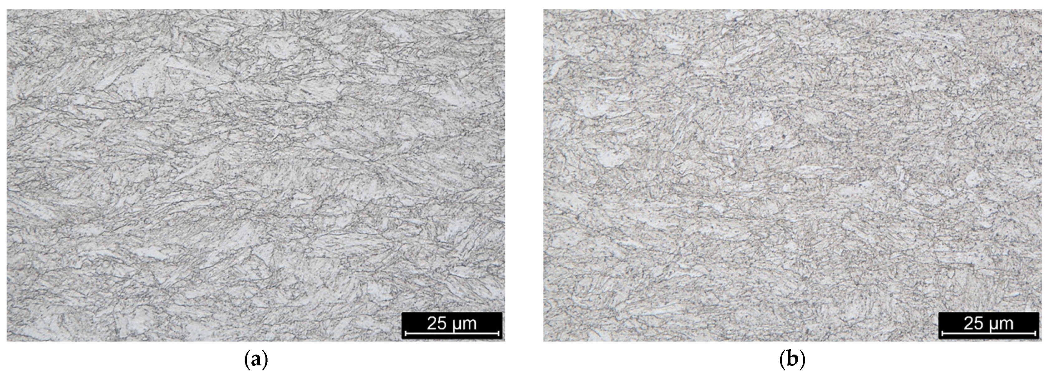
Figure 1. Microstructure of the S960MC sheet metal in axial (a) and tangential (b) orientation with respect to the rolling direction.
Materials 19 02062 g001
Figure 2. Experimental samples and process of welding: (a) shape and geometry of the samples; (b) the real manufactured sample; (c) location of the autogenous line weld joint on Samples 1–3; and (d) location of the butt weld joint on Samples 4–5. The red lines designate the weld location.
Materials 19 02062 g002
Figure 3. Scheme of the residual stress analysis positions on welded samples: (a) scheme of the residual stress analysis locations concerning the weld joint and (b) the scheme of residual stress analysis locations concerning the HAZ.
Materials 19 02062 g003
Figure 4. Welding residual stresses–beginning of the weld joints–surface: (a) axial direction and (b) tangential direction.
Materials 19 02062 g004
Figure 5. Welding residual stresses–middle of the weld joints–surface: (a) axial direction and (b) tangential direction.
Materials 19 02062 g005
Figure 6. Welding residual stresses–end of the weld joints–surface: (a) axial direction and (b) tangential direction.
Materials 19 02062 g006
Figure 7. Welding residual stresses–beginning of the weld joints–a depth 0.2 mm: (a) axial direction and (b) tangential direction.
Materials 19 02062 g007
Figure 8. Welding residual stresses–middle of the weld joints–a depth 0.2 mm: (a) axial direction and (b) tangential direction.
Materials 19 02062 g008
Figure 9. Welding residual stresses–end of the weld joints–a depth 0.2 mm: (a) axial direction and (b) tangential direction.
Materials 19 02062 g009
Figure 10. Hardness traverse measurement through the welded joint: (a) Sample 1; (b) Sample 2; (c) Sample 3; (d) Sample 4; and (e) Sample 5. The color dots represent the hardness measured in the specific weld location and dashed lines designate the approximate boundary between the individual heat affected subzones.
Materials 19 02062 g010aMaterials 19 02062 g010b
Table 1. Chemical composition of S960MC per inspection certificate (EN 10204 3.1a).
Chemical Composition [wt. %]
CMnSiPSCrMoNiNbTiVAlFe
0.0791.7910.2820.0030.0030.2100.2690.0180.0050.0090.0300.055Balance
Table 2. Mechanical properties of S960MC.
Yield Point Rp0.2 [MPa]Ultimate Tensile Strength Rm [MPa]Ductility A [%]
109511607
Table 3. Welding parameters for sample manufacturing.
Sample No.Welding Voltage UW [V]Welding Current IW [A]Welding Speed VW [cm/s]Heat Input Q [kJ/cm]Cumulative Heat Input
[kJ]
Welding MethodShielding GasFiller Metal
112.31350.352.940.6TIGArnone
212.31700.353.650.4TIGArnone
3—surface12.61700.353.751.8TIGArnone
3—root12.31250.352.636.4TIGArnone
412.61750.353.857TIGArnone
512.31610.54.872MAG82% Ar + 18% CO2G3Si1
Table 4. The reference value of the residual stresses in the as-received material.
SurfaceDepth 0.2 mm
AxialTangentialAxialTangential
Residual stress [MPa]−61−183−32−93
Table 5. Width of the HAZ.
Sample No.Width [mm]Heat Input Q [kJ/cm]
111.22.9
212.83.6
313.83.7 + 2.6
412.93.8
511.64.8
Disclaimer/Publisher’s Note: The statements, opinions and data contained in all publications are solely those of the individual author(s) and contributor(s) and not of MDPI and/or the editor(s). MDPI and/or the editor(s) disclaim responsibility for any injury to people or property resulting from any ideas, methods, instructions or products referred to in the content.