Article

Recycling Fiber-Reinforced Polyamide Waste from the Automotive Industry: Life Cycle Assessment (LCA) of an Advanced Pyrolysis Process to Reclaim Glass Fibers and Valuable Chemicals

by
Blanca María Caballero
1,
Alexander Lopez-Urionabarrenechea
1,*,
Jean Paul Gonzalez-Arcos
2,
Borja Benjamín Perez-Martinez
1,
Esther Acha
1,
Maider Iturrondobeitia
3,
Julen Ibarretxe
4,
Aritz Esnaola
5 and
Maider Baskaran
5
1
Department of Chemical and Environmental Engineering, Faculty of Engineering of Bilbao, University of the Basque Country (UPV/EHU), Plaza Ingeniero Torres Quevedo, 1, 48013 Bilbao, Spain
2
Department of Organic and Inorganic Chemistry, Faculty of Science and Technology, University of the Basque Country (UPV/EHU), P.O. Box 644, 48080 Bilbao, Spain
3
Department of Graphical Design and Project Engineering, Faculty of Engineering of Bilbao, University of the Basque Country (UPV/EHU), Plaza Ingeniero Torres Quevedo, 1, 48013 Bilbao, Spain
4
Department of Applied Physics, Faculty of Engineering in Bilbao, University of the Basque Country (UPV/EHU), Paseo Rafael Moreno “Pitxitxi” 3, 48013 Bilbao, Spain
5
Polymer and Composites Technology, Mechanical and Industrial Production Department, Faculty of Engineering, Mondragon Unibertsitatea, Campus Orona Ideo, Fundazioa Eraikuntza, Jauregi Bailara, 20120 Hernani, Spain
*
Author to whom correspondence should be addressed.
Materials 2025, 18(7), 1594; https://doi.org/10.3390/ma18071594
Submission received: 7 March 2025 / Revised: 27 March 2025 / Accepted: 29 March 2025 / Published: 1 April 2025

Abstract

:
The generation of pyrolysis liquids and gases with poor quality is a limiting factor for the development of the recycling process of fiber-reinforced plastic waste. In this article, the life cycle assessment (LCA) of an advanced two-step pyrolysis process to recycle glass fiber-reinforced polyamide waste is presented. First, the solid waste is pyrolyzed by heating up at 3 °C/min to 500 °C in a tank reactor. The generated volatiles are subsequently thermally cracked at 900 °C in a tubular packed bed reactor. The process is able to reclaim the glass fibers similarly to the conventional one reactor pyrolysis, while producing liquids and gases with better properties. The large quantity of oxygenated pyrolysis oils generated in the conventional pyrolysis are cracked into gaseous hydrocarbons, CO, CO2 and a minor aqueous liquid. The pyrolysis gases become the main product of the process, presenting an interesting composition of hydrogen (39.9 vol.%), methane (22.5 vol.%), carbon monoxide (19.5 vol.%) and ethylene (10.8 vol.%). The LCA shows that advanced pyrolysis demonstrates better environmental performance than conventional pyrolysis, avoiding fossil resource scarcity and reducing global warming by half and human carcinogenic toxicity by one third.

1. Introduction

Fiber-reinforced plastics (FRPs) are progressively moving into the automotive sector. Their fabulous strength-to-weight ratio allows for the construction of light vehicles, which consequently leads to less fuel consumption and lower CO2 emissions per driven kilometer. These materials, reserved until recently for racing cars and top-of-the-range vehicles, are now projected to double in revenue by 2032 in the automotive sector [1]. The main stimuli for this growth are the need for new materials to decrease the weight of some structures in future electric vehicles (e.g., the battery enclosure) and the development of faster FRP manufacturing technologies able to work at the high production volumes that characterize the automotive industry [2]. However, the environmental benefits of using these lightweight materials in vehicles are constrained by the challenges they present to be completely recycled at the end of life. While it is quite clear that fibers can be recovered from FRP and be reused in the automotive sector itself [3,4], there are well-founded uncertainties about the recyclability of the plastic part of these materials, commonly a thermoset resin [5,6]. Therefore, the integration of FRP in the automotive sector may pose a problem in meeting the circularity requirements for vehicle design planed by the European Commission. This proposal includes, among many other objectives, a 30 wt.% recycling target for plastics in vehicles and a recycled plastic content of 30 wt.% in manufactured vehicles in 2031 [7]. Consequently, the market is shifting towards thermoplastic FRP [8].
Thermoplastics are increasingly used over thermoset composites due to their design flexibility, ease of processing and recyclability, making them ideal for cost-effective, high-volume production. In the automotive industry, manufacturing technologies such as injection molding and compression molding are extensively employed for producing semi-structural or interior components with complex geometries [9]. Glass mat-reinforced thermoplastic (GMT) is a type of FRP composed of a thermoplastic matrix and a glass fiber framework. GMT is widely used in the automotive sector due to its high mechanical strength, short forming cycles and dimensional stability. The use of GMT in automotive applications offers several advantages. Its high mechanical strength ensures durability and performance under various conditions. The short forming cycles associated with GMT allow for efficient production processes, reducing manufacturing time and costs. Additionally, the dimensional stability of GMT ensures that components maintain their shape and fit precisely within assemblies, enhancing overall vehicle quality [10]. Thermoplastic FRPs should be, in principle, more recyclable due to the possibility of re-melting their plastic matrix or re-shaping them, but there are still significant challenges around the mechanical recycling of these materials [8,11,12,13].
In this scenario, pyrolysis is the FRP recycling technique that has reached the highest technology readiness level (TRL) up to now [14]. In this process, the plastic matrix is thermally decomposed (without feeding air), generating volatile substances that separate into liquids and gases when cooling down. The fibers are not decomposed during the thermal process and can be recovered together with the carbonization solid products derived from the plastic decomposition [15]. Pyrolysis is a versatile technique that can be applied to FRP containing cured thermoset resins, uncured thermoset resins, thermoplastics and other non-plastic materials (wood, paints and metals), which constitutes a competitive advantage over other FRP recycling processes. Additionally, the pyrolysis gases, rich in light hydrocarbons, can be used as energetic source for the process. However, there is an issue not solved for the moment: the lack of applications for pyrolysis liquids. This product, which theoretically could be used in refineries or as petrochemical feedstock, is usually a very complex mixture of oily and aqueous phases polluted with heteroatoms, which restricts its possible applications [16,17].
The authors of this article have studied a two-step pyrolysis process for many years, where the pyrolysis volatiles are subjected to a thermal or thermal–catalytic treatment before cooling down and condensing. The aim is to minimize the pyrolysis liquids by converting their organic content into hydrogen, carbon monoxide and light hydrocarbons in the pyrolysis gases [18,19]. This advanced pyrolysis process has been successfully applied to manufacturing and end-of-life FRP waste composed of cured and uncured epoxy, polyester and phenolic thermoset resins. The results up to now are promising and the preliminary economic analysis suggests that the process could have competitive advantages compared to conventional pyrolysis [17]. However, the process requires the employment of an additional reactor with associated material and energetic consumption, which suggests that its environmental impact could be greater than that of conventional pyrolysis. Therefore, the main objectives of this article are two: (1) To evaluate the performance of the advanced pyrolysis process applied to a thermoplastic FRP waste from the automotive industry, specifically a polyamide-based GMT. (2) To assess the environmental impact of the advanced pyrolysis in comparison to conventional pyrolysis and to landfill through the life cycle assessment (LCA) methodology. The results presented in this article are regarded as innovative, as there is no published research on the performance and LCA-based environmental analysis of the two-step pyrolysis process for residual glass fiber-reinforced polyamide. The industrial implementation of the recycling process studied in this article could break down the barriers to the mass use of fiber-reinforced plastics in the automotive industry, making GMT a viable and environmentally responsible choice for modern automotive manufacturing.

2. Materials and Methods
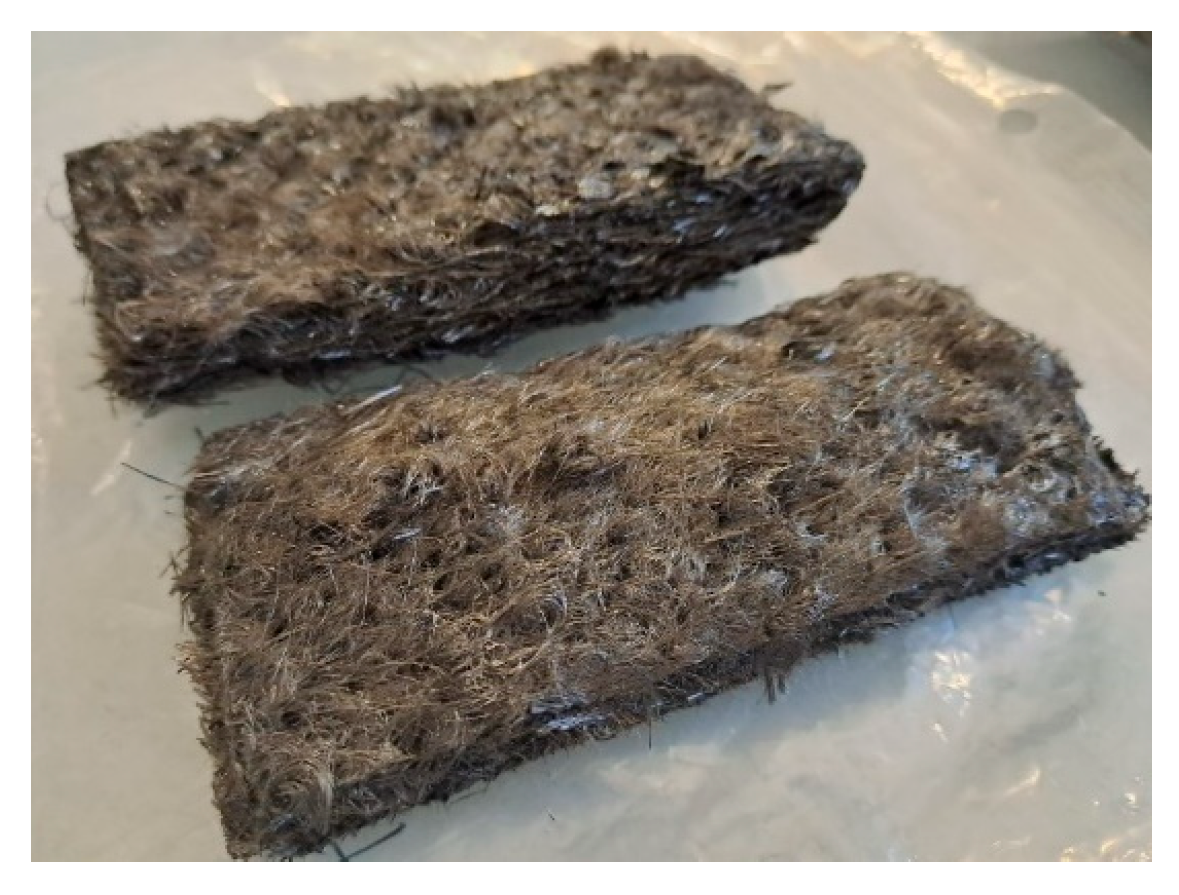
2.1. Raw Material

The sample used in this work was automotive GMT manufacturing waste, based on a glass mat-reinforced polyamide-6 composite. The original GMT was provided by Mitsubishi Chemical Advance, with a glass fiber volume content (υf) of 17% and 1.374 g/cm3 material density. The waste was received in monolithic pieces of 10 cm × 30 cm and was cut into samples of 5 cm × 15 cm for the pyrolysis tests (see Figure 1). Furthermore, a small amount of sample was milled down to an approximate particle size of 2 mm for characterization.

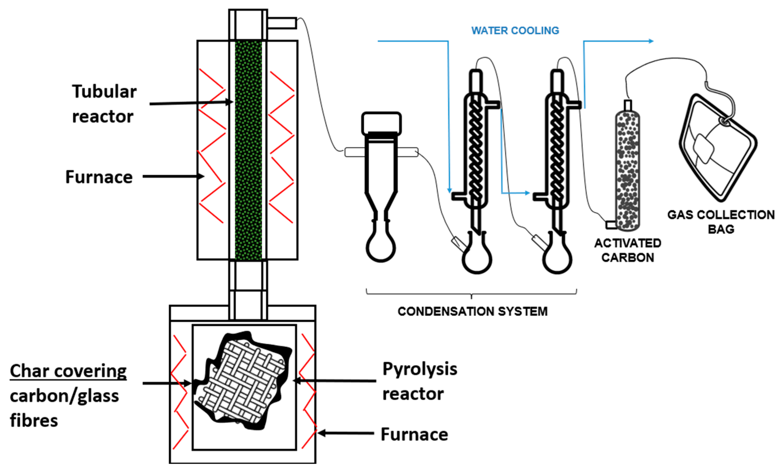
2.2. Experimental Procedure

Figure 2 shows the experimental setup of the laboratory scale installation used for the conventional pyrolysis and the advanced pyrolysis (with volatiles’ thermal treatment) tests. As can be seen in the scheme, the installation consists of two thermal units connected in series and a condensation and collection system. The first one is formed by a 3 L non-stirred tank reactor heated by an electric furnace, where the pyrolysis is carried out and the solid product generated in the process is deposited. The second unit consists of a fixed bed tubular reactor (2 cm inner diameter and 60 cm long) heated by an electric furnace and connected in series to the first one. In this reactor, the volatiles generated in the pyrolysis reactor are thermally treated, increasing their residence time at high temperatures. Thus, the large pyrolytic molecules are cracked, forming smaller substances, which leads to the minimization of liquids and the maximization of gases. The installation is completed by a condensation system for liquid–gas separation and an activated carbon column for gas cleaning.
In each of the experiments of this work, 100 g of glass fiber-reinforced polyamide were pyrolyzed in the first reactor at 500 °C, using a heating rate of 3 °C min1, a dwell time of 30 min and no N2 input. In the case that no treatment of volatiles was carried out (conventional pyrolysis), the pyrolysis reactor outlet was connected directly to the condensation system, generating liquids and gases. In the experiments with volatiles’ treatment (advanced pyrolysis), the volatiles produced in the pyrolysis reactor were thermally treated at 900 °C in the tubular reactor (second reactor), containing a solid bed of high alumina refractory brick of 0.5–1 mm particle size. These bricks were a residual material coming from defective bricks and were regenerated after each experiment by combustion at 700 °C in a muffle oven.
Pyrolysis liquids and solid yields were determined by the weight difference in the condensers, pipelines and pyrolysis reactor before and after the experiments, since the gas yield was calculated by the difference to 100.

2.3. Analytical Techniques

The initial sample and the pyrolysis products obtained were characterized by employing the following analytical techniques:
Thermogravimetric analysis
The thermogravimetric profiles of the initial sample were obtained in a Mettler-Toledo (Greifensee, Switzerland) TGA/SDTA851 thermobalance by means of dynamic analysis, heating the sample from 30 to 900 °C under a 10 °C/min heating rate in a 50 mL/min N2 atmosphere.
Proximate analysis
The thermogravimetric balance LECO (St. Joseph, MI, USA) TGA-701 was used for the proximate analysis of the initial sample, following the EN ISO 21660-3:2021 (moisture), EN ISO 22167:2022 (volatile matter) and EN ISO 21656:2021 (ash) standards.
Elemental analysis (CHNO)
The CHN elemental analysis was determined with a LECO (St. Joseph, MI, USA) TruSpec CHN automatic analyzer according to the EN ISO 21663:2021 standard. The elemental oxygen (O) was analyzed in a Eurovector (Pavia, Italy) Euro EA elemental analyzer.
Lower Heating Value (LHV)
The automatic calorimeter LECO (St. Joseph, MI, USA) AC-500 was used for the determination of the higher heating value (HHV) of solid and liquid samples, complying with the EN ISO 21654:2022 standard. Then, the LHV was calculated by correcting the HHV with the hydrogen content of the samples. In the case of gases, the LHV was calculated theoretically based on the LHV of the substances composing them.
Analysis of halogens and sulfur
The elemental analysis of halogens (Cl, Br and F) and sulfur (S) was carried out following the EN 14582:2016 standard. This analysis consists of burning the sample in a calorimeter and absorbing the combustion acid gases (HCl, HBr, HF and SO2/SO3) in a basic solution. Then, chlorine, bromine, fluorine and sulfur are determined as chloride, bromide, fluoride and sulphate, respectively, by ion chromatography. In this procedure, the LECO AC-500 calorimeter, a NaOH 0.25 M solution and a Dionex (Sunnyvale, CA, USA) ICS 3000 ion chromatograph were used.
Composition of gases
The composition of gases was quantitatively determined using an Agilent (Santa Clara, CA, USA) 7890A gas chromatograph (GC) with a thermal conductivity detector (TCD) and a flame ionization detector (FID). The GC was a double column chromatograph equipped with a molecular sieve for H2, O2, N2, CO and CH4 separation and a column for separation of CO2 and hydrocarbons higher than C1. The coordination to split the substances between the molecular sieve and the column is automatized by a valve system in the GC. The GC was calibrated with a standard gas mixture with the following composition: CO2 15 vol.%, H2S 5 vol.%, H2 20 vol.%, CO 20 vol.%, CH4 20 vol.%, C2H4 5 vol.%, C2H6 5 vol.%, C3H6 5 vol.%, C3H8 3 vol.%, 1-butene 1 vol.% and 1-pentene 1 vol.%.
Composition of liquids
The composition of liquids was qualitatively determined by gas chromatography (GC, Agilent 6890, Santa Clara, CA, USA) coupled to a mass spectrometer (MS, Agilent 5973, Santa Clara, CA, USA). Such compounds with a match quality provided by the MS search engine lower than 85% were classified as “not identified”. ε-Caprolactam (99%, Sigma-Aldrich, Burlington, MA, USA) was used to calibrate this substance in the GC-MS system in order to get its concentration in wt.%. Four-point calibration was carried out using 1-propanol (99.8%, Supelco, Burlington, MA, USA) as the internal standard.

2.4. Life Cycle Assessment (LCA)

The LCA was carried out with the OpenLCA software (version 2.3) coupled with the Ecoinvent v3.10 database, following the methodology of the ISO 14040 standards. The results were categorized into eighteen environmental impact indicators by means of the ReCiPe 2016 Midpoint (H) method [20]. The functional unit (FU) was 1 t of glass fiber=reinforced polyamide. The inventory of the LCA is shown in Table 1, which includes the inputs and outputs of the pyrolysis process in each case, as well as the selected process for landfill. The material and energy inputs were as follows: (1) the energy necessary to heat the reactors using natural gas as fuel, (2) activated carbon used for gas cleaning and (3) water used for cooling the condensers. The energy consumption of the reactors was calculated from a previous work of the authors [19], while the quantity of activated carbon and water was estimated from the data of the laboratory experiments. The output flows representing the pyrolysis products were selected taking into account their characterization results, which will be explained in the “Results and discussion” section. Additionally, the spent activated carbon coming from the gas cleaning was also taken into consideration as a waste output of the pyrolysis processes.

3. Results and Discussion

3.1. Characterization of the Glass Fiber-Reinforced Polyamide Sample

Table 2 presents the results of the proximate and elemental analysis, as well as the lower heating value (LHV) of the feedstock, including the mean value of at least three equivalent measures that did not differ more than 3 points in wt.% from one to another, and their standard deviation. The analyses were conducted as received (ar) and the results were also calculated as dry and ash free (daf) basis in order to infer the properties of the polyamide matrix. The proximate analysis showed that the sample consisted mainly of volatile matter (69.3 wt.%) and ash (27.0 wt.%), with low moisture and fixed carbon contents (2.3 and 1.4 wt.%, respectively). The low moisture content was expected, since it is typical of plastics, while the ash content was mainly derived from the glass fibers of the sample, together with some inorganic additives that could be part of the GMT formulation, e.g., alumina, kaolin, talcum, calcium carbonate, barium sulfate or titanium dioxide [18]. On the other hand, the daf results showed the nature of the polyamide. It can be seen that the polyamide was constituted almost completely of volatile matter, which indicated the high tendency of the polymer to generate liquids and gases under pyrolysis conditions. On the other hand, the low fixed carbon content meant that the polyamide did not have a tendency to carbonize, which, taking into account that carbonized products remain with the fibers after the pyrolysis process, is a desirable property in terms of reclaiming clean glass fibers through pyrolysis.
Regarding the elemental analysis, the main elements of the sample were carbon (42.9 wt.%), oxygen (8.6 wt.%), nitrogen (8.4 wt.%) and hydrogen (6.4 wt.%). These results were consistent with the nature of polyamide, where the amide functional group is composed of such elements (-CO-NH-). In fact, the results as daf basis corresponded well with those reported in the literature for pure polyamide PA6 [21]. Halogens and sulfur were also analyzed, but the results obtained were below the quantification limit of the equipment, indicating non-existence or trace quantities. Finally, the LHV of the sample presented a typical value for plastics reinforced with similar glass fiber content (≅20 MJ kg−1) [22]. Its value as daf basis corresponded well also with that reported in the literature for polyamide [21].
Figure 3 shows the thermogravimetric behavior of the glass fiber-reinforced polyamide sample. In this figure, a dash line has been added at 500 °C, the temperature of the pyrolysis experiments. The thermogravimetric profile (TGA) allows observing of the weight loss of the sample when it is heated from room temperature up to 900 °C, while the first derivative of the mass loss (DTA) allows determining of the temperature at which the highest rates of weight loss occurs. This analysis can help to decide the most appropriate pyrolysis temperature for the sample. It can be observed that the FRP sample decomposed in a single step in the interval 320–500 °C, presenting the maximum degradation rate at 455 °C. Similar thermogravimetric behavior has been reported by other authors with glass fiber-reinforced polyamide6 [23], pure polyamide PA6 [24] and nylon (polyamide) [25]. In this case, it is clear that 500 °C is a high enough temperature in order to obtain the complete degradation of the polyamide, since no significant weight loss was observed from 500 °C to 900 °C. The remaining weight of the sample, which should approximately correspond to the sum of glass fiber and fixed carbon content, was lower than the ash content of the sample (22 wt.% vs. 27 wt.%). This was probably due to a loss of fiber as a consequence of the sample milling process, since glass fibers have the tendency to agglomerate, generating fiber-enriched zones and resin-enriched zones in the milled sample. This effect can be more pronounce when low sample quantities are employed, as is the case in TGA analysis.

3.2. Pyrolysis Yields

Table 3 shows the pyrolysis yields obtained for the glass fiber-reinforced polyamide sample studied, without (conventional) and with (advanced) thermal treatment of volatiles. The results shown in the table are the average and standard deviation values of two experiments for each configuration. It can be observed that in the conventional pyrolysis process, the liquid fraction was the main product (59.8 wt.%), followed by the solid fraction (34.8 wt.%) and a small amount of gases (5.4 wt.%). The sum of the pyrolysis liquid and gas yields (65.2 wt.%) was lower than the sum of volatile matter and moisture contents of the original sample (71.2 wt.%). This result indicated that some of the volatile matter of the sample remained in the pyrolysis solid after the experiment, which can be explained by the difference between the temperature used in the volatile matter analysis (950 °C) and the temperature used in pyrolysis (500 °C). The same fact explained that the solid yield was higher than the ash plus fixed carbon contents of the sample (28.4 wt.%).
In the advanced pyrolysis experiments, a significant decrease in the yield of liquids was observed (from 59.8 wt.% to 21.1 wt.%), and consequently an increase in gas yields, which became the main fraction (44.0 wt.%). This result was expected due to the experimental configuration used in advanced pyrolysis experiments, where the pyrolysis volatiles passed through the tubular reactor at 900 °C, increasing their residence time at high temperatures, which promotes the cracking of the pyrolysis volatiles into small substances. This behavior has been repeatedly observed by the authors in previous research carried out with many types of fiber-reinforced plastic waste [18,19], as well as by other authors using a two-reactor configuration [26].
With respect to the pyrolysis solids, the solid yields did not show significant changes (≅35 wt.%). This was also expected, since the operating conditions of the pyrolysis reactor were the same in both types of experiments.

3.3. Pyrolysis Gases

The composition (vol.% and wt.%) and LHV of the pyrolysis gases obtained at 500 °C, without and with volatiles’ thermal treatment at 900 °C, are presented in Table 4. These values are given as dry basis and free of nitrogen, oxygen and other substances that cannot be identified in the GC configuration presented in Section 2.3. The chromatograms generated with the FID and TCD detectors of the GC analysis of the gases are shown in Figure 4.
Table 4 shows that the composition in vol.% of the gases obtained in the conventional pyrolysis experiments was dominated by hydrogen (47.4 vol.%), followed by CO2 (18.8 vol.%) and CO (8.4 vol.%), together with hydrocarbons in the range of 2–7 vol.%. The high percentage of hydrogen could suggest the possibility of separating it to produce pure hydrogen. However, the most mature technology for hydrogen separation, the pressure swing adsorption (PSA), is usually employed with feeding gases containing 55 vol.% or higher percentages of hydrogen [27]. Although the percentage of hydrogen of these pyrolysis gases was close to 55 vol.% and there are works that demonstrate that PSA can be used for feeding gases containing 40 vol.% of H2 [28], it must be remembered that the gas yield of this experiment was low (5.4 wt.%, Table 3) and this operation would probably not be economically competitive. In fact, the third column of Table 4 shows that the total quantity of hydrogen produced in conventional pyrolysis would be 2.5 g/kg waste, which means a hydrogen yield of approximately 8%. Therefore, these gases could be assimilated to a kind of low quality syngas or may be used to blend with refinery off-gases.
On the other hand, the gases produced in the advanced pyrolysis showed a composition also dominated by hydrogen (39.9 vol.%), methane (22.5 vol.%), carbon monoxide (19.5 vol.%) and ethylene (10.8 vol.%), lowering the concentration of CO2 down to 5.6 vol.%. Additionally, it has to be borne in mind that the yield of gases in this experiment was higher than that of the experiment without thermal treatment (44.0 vs. 5.4 wt.%). These gases could find better applications than those of the gases of the conventional pyrolysis due to the following reasons. (1) The concentration of hydrogen is high enough to be separated as pure hydrogen (≈40 vol.%), with a gas production rate of 0.44 kg/kg waste, a H2 production rate of 22 g/kg waste and a H2 yield of almost 70%. (2) This gas could be a good quality syngas due to the better composition in terms of CO and CH4. (3) The proportion of ethylene could open the possibility to blend the gas with the steam cracker off-gases to be used as polyethylene feedstock, which would be the most circular alternative in terms of plastic-to-plastic (P2P) [29].
In order to be able to discuss the formation or consumption tendency of each substance between the two experiments, the total quantity of each gaseous substance was calculated in both cases, without and with volatiles’ treatment. These results showed a specially high formation tendency for CO (×25), CH4 (×35) and C2H4 (×25), and, to a lesser extent, for H2 (×9) and CO2 (×3), when thermal treatment was used. The high production of light gases is the direct consequence of the high temperature thermal cracking that took place in the tubular reactor. In this reactor, all the pyrolysis volatiles (gases and vapors) suffered a severe thermal cracking that led to the high production of small gaseous molecules. This behavior has been observed before by the authors in their experience working with this kind of waste and plant configuration [18,19]. Concerning the LHV, it can be seen that both gases presented quite similar values, comparable to those of other gaseous fuels such as synthesis gas (10–20 MJ Nm−3) and landfill biogas (20 MJ Nm−3).
The FID chromatogram of the gas derived from the conventional pyrolysis, given in Figure 4, showed a good definition among C1–C3 hydrocarbons, while the high quantity of substances in the C4 and C5 carbon atom number range led to the typical “dinosaur-like” compilation of non-resolved peaks of complex mixtures. The TCD chromatogram seems to be more complicated by the fact that TCD is more sensitive to valve change and that hydrocarbons also generate peaks in this detector. However, the only signals obtained from TCD were those of CO, CO2 and H2, the last one with a change of polarity to avoid an inverted peak with respect to the conductivity of helium, used as the carrier gas. In agreement with the gas composition shown in Table 4, the FID chromatogram of the advanced pyrolysis gas clearly showed a more simplified mixture dominated by methane and ethane, while the TCD presented a lower peak for CO2.

3.4. Pyrolysis Liquids

Table 5 shows the results of the GC-MS analysis, the elemental analysis and the LHV of the pyrolysis liquids, both in conventional and advanced pyrolysis. Regarding the composition of the liquids without volatiles’ treatment, the GC-MS analysis showed a qualitative composition dominated by caprolactam (90.7 area %). In view of such a high area percentage, calibration and quantitative determination of caprolactam in the liquids was carried out, resulting in 43.9 wt.%. This big difference between the GC-MS results in area % and wt.% are typical of some substances when analyzing complex pyrolysis liquids, as the authors demonstrated in a previous paper [30]. Therefore, it should be remembered that equating MS area % to wt.% for some substances present in pyrolysis liquids can result in large errors and a calibration procedure is always needed when the concentration of a single substance is sought. In any case, caprolactam was clearly the main substance in the pyrolysis liquids. The tendency of polyamide to depolymerize into caprolactam by thermal decomposition is a well-known fact in the literature since several years ago [21,23,24,31,32,33]. De Rezende Locatel et al. have recently reported that caprolactam could be formed through two reaction pathways [34]. (1) The cyclization of hexene-5-amide after cleavage of C-N bonds and cis-elimination, and (2) the cyclization of aminocaproic acid after hydrolysis of two amide linkages.
The elemental analysis of the pyrolysis liquid without thermal treatment showed a composition led by carbon (57.3 wt.%), followed by similar proportions of hydrogen, nitrogen and oxygen (≈10 wt.%). These results corresponded quite well with the elemental composition of caprolactam (≈64 wt.% C, 10 wt.% H, 12 wt.% N and 14 wt.% O), the main substance in the liquids, with some differences due to the presence of other substances. However, the high percentage of “others” was surprising, since, attending to the elemental analysis of the FRP sample, they could not be halogens or sulfur. The most probable explanation for this result could be the presence of some inorganic element (Ca or B) coming from the polyamide additives in this pyrolysis liquid, which would not have been burned in the CHN analyzer, being accounted for as “other elements” by the difference to 100. Concerning LHV, a quite high value was obtained for this pyrolysis liquid, similar to that of liquid fossil fuels.
The volatiles’ thermal treatment performed in the advanced pyrolysis completely changed the nature of the pyrolysis liquid, with water being the unique substance identified in the GC-MS. The formation of water during the thermal decomposition of polyamide is assumed in the literature when hydrolysis is identified as one possible reaction step [25,31,32,34]. In this case, the appearance of an aqueous phase as a product was one of the consequences of the cracking of the oxygenated organic substances present in the pyrolysis volatiles. The literature reports that the precursors for the formation of water under pyrolysis conditions are oxygenated functional groups, such as -OH and -COO-, which can be present both in the original sample and in the pyrolysis-derived products [35,36]. These kinds of functional groups can be easily formed during the cracking of the pyrolysis volatiles of polyamide. The elemental analysis revealed a composition dominated by oxygen (47.2 wt.%), followed by similar proportions of hydrogen, nitrogen and carbon (≈ 10 wt.%). Again, the percentage attributed to other elements was high (22.0 wt.%), this time probably due to the fact that the actual percentage of oxygen was underestimated, since the O analyzer is normally calibrated up to 22.1 wt.%. The presence of carbon and nitrogen suggested that this pyrolysis liquid was an aqueous liquid containing organic substances in solution. In order to know what kind of substances could be present in the pyrolysis liquid, a GC-MS analysis in a water-free basis was performed. This analysis revealed the predominant presence of nitriles (propenenitrile, acetonitrile, benzonitrile, butanedinitrile and naphthalenecarbonitrile), which have been previously reported as typical products of the pyrolysis of polyamides [37]. This is attributed to the severe thermal cracking of the organic substances that compose the pyrolysis volatiles to give light hydrocarbons, CO/CO2, H2 and coke. The results shown in this article demonstrate that this process can be also applied to polyamide with similar results, which constitutes the first time this is applied to a thermoplastic-based FRP.

3.5. Pyrolysis Solids

Figure 5 shows a sample of the solid product generated in the pyrolysis tests of the glass fiber-reinforced polyamide samples studied in this work. As it can be seen, the pyrolysis solids were a kind of glass fiber covered by char, presenting the typical blackened aspect of the solid product obtained in the pyrolysis of glass fiber-reinforced plastics [38,39]. Table 6 shows the proximate and elemental analyses of the pyrolysis solids obtained both in the tests without and with thermal treatment of the vapors. First, it must be said that the results of both analyses were almost the same for the two samples (without and with thermal treatment), since the pyrolysis operating conditions in the first reactor remained constant.
The presence of carbonaceous substances covering the glass fibers was confirmed by the proximate analysis (Table 6), which showed that the pyrolysis solids still contained around 11 wt.% of organic matter (volatile matter + fixed carbon). As expected, the ash value was the highest one, since the glass fiber content is accounted as ash in the proximate analysis. These results were confirmed by the elemental analysis, where approximately 9 wt.% of carbon was found, together with trace quantities of hydrogen and nitrogen. In this case, the “others” probably corresponded mostly to oxygen. The results of the proximate and elemental analyses of the pyrolysis solids were very similar to those obtained by the authors in previous works concerning pyrolysis of glass FRP [18,19]. These char-covered fibers can be effectively cleaned by a controlled oxidation process in order to obtain recycled glass fibers that could be reused in manufacturing processes [40,41].

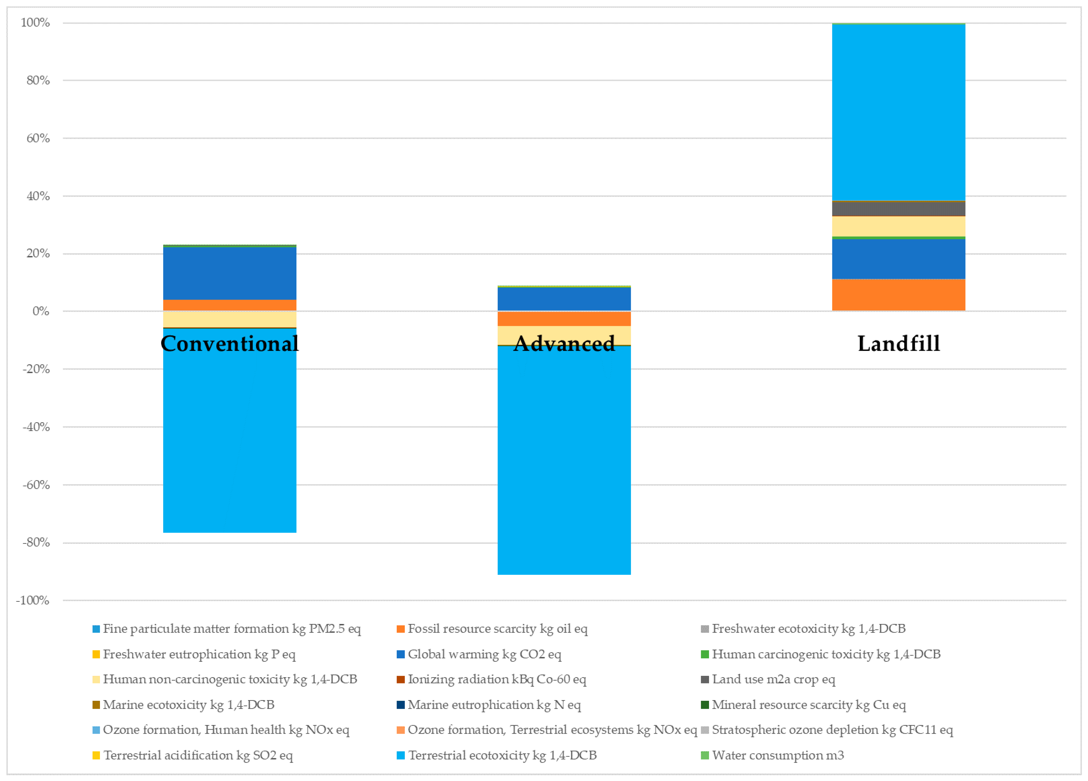
3.6. Life Cycle Assessment (LCA)

The main goal of the LCA was to assess and compare the environmental impacts of the conventional and the advanced pyrolysis processes, while at the same time comparing these recycling processes with the FRP waste disposal in landfill, the most used treatment route for this type of waste currently. The main difference between the two pyrolysis processes was the energy consumption. As can be seen in Table 1, the energy consumption was estimated to be 3650 kWh/t in the conventional pyrolysis, while it was 7058 kWh/t, almost double, for the advanced pyrolysis. The additional contributions to the energy consumption in the advanced pyrolysis were the use of a second reactor working at high temperatures (900 °C) and the regeneration of the solid bed material of this reactor, which was also thermally done. The energy consumption of the second reactor was lower than that of the first reactor despite working at a higher temperature. There are two main reasons for this: (1) the size of the second reactor is smaller and, consequently, it is normally more efficiently heated, and (2) the vapors entering this second reactor were pre-heated in the first one. Regarding the material consumption of the advanced pyrolysis, the use of the refractory material in the solid bed was not considered to have an environmental impact because it was produced from residual refractory bricks. Additionally, this material can be regenerated and reuse for many cycles without losing its performance.
Both pyrolysis processes were considered to be producers of recycled and reusable glass fibers, while the pyrolysis liquids and gases were assimilated to different products depending on their properties. In the case of the conventional pyrolysis, pyrolysis liquids could be initially considered a source of caprolactam for the production of secondary polyamide. However, more than half of the pyrolysis liquids (56.1 wt.%) were composed of unknown substances, so this pyrolysis liquid should be purified and upgraded through a sequence of different treatment steps before using it as a secondary caprolactam source. Additionally, it must be highlighted that the polymerization quality of caprolactam is very sensitive to impurities and very low quantities of them have been reported as responsible for decreasing its properties [42,43]. Therefore, based on their LHV and the low (or nonexistent) concentration of S and Cl, the selected application for the liquids of the conventional pyrolysis was to be refuse derived fuel (RDF) for cement kilns. Although the concentration of polychlorinated biphenyls (PCBs) and metals should be determined prior to being accepted in cement kilns, this was considered a realistic application for such pyrolysis liquids, taking into account that the concentration of PCB and metals in pyrolysis liquids is low even when high chlorinated and metal-polluted waste is pyrolyzed [29]. Additionally, the FRP waste used in this work was not an end-of-life waste, which is normally more polluted [44]. Concerning the gases of the conventional pyrolysis, they were assimilated to low-quality refinery gases (waste refinery gas) due to the high percentage of CO2. In the case of the advanced pyrolysis, the liquids were a kind of industrial wastewater polluted with organic substances. Therefore, an “average” wastewater was selected as the output flow in the LCA software (OpenLCA version 2.3) to represent this liquid fraction. On the other hand, the pyrolysis gases presented a better composition than that of the pyrolysis gases of the conventional pyrolysis, so they were assimilated to refinery gas, a gas to be used in general petroleum refinery operations.
The results of the LCA are shown in Table 7 and Figure 6 and Figure 7. Table 7 shows the values of all the considered impact categories for the two pyrolysis processes and the landfill. As it can be seen, negative and positive values were obtained, those of landfill being the highest ones by far, various orders of magnitude higher than those of the pyrolysis processes in the majority of the categories. This indicated the worst treatment option for this kind of waste from an environmental point of view. However, Yousef et al. reported that conventional pyrolysis presented a higher environmental impact than landfill in the categories of terrestrial acidification, ozone formation (for both terrestrial ecosystems and human health) and fine particulate matter formation [45]. The key question explaining these differences is if pyrolysis is considered in LCA to be a recycling process where products are obtained. This was demonstrated by Pillain et al., who showed that the environmental impacts of various recycling techniques for FRP waste were higher compared to landfill and incineration when recycled products were not considered [46]. As can be seen in the inventory of the present study (Table 1), recycled glass fibers were considered to be obtained as a product in both pyrolysis processes and, in the case of the advanced pyrolysis, refinery gas was also considered an output.
When recycled products are considered in the LCA, the environmental impacts give negative results in calculation due to the avoided impacts derived from the substitution of primary products and materials by the recycled ones. This is the reason why some values in Table 7 were negative. Therefore, it can be said that both pyrolysis processes avoided impacts in the categories of freshwater ecotoxicity, human non-carcinogenic toxicity, ionizing radiation, marine ecotoxicity, mineral resource scarcity, stratospheric ozone depletion and terrestrial ecotoxicity. Additionally, advanced pyrolysis also avoided impacts in fossil resource scarcity, marine eutrophication and ozone formation (for both terrestrial ecosystems and human health) categories.
The contribution in percentage of the different impact categories is shown in Figure 6. The category with the highest impact in the case under study was terrestrial ecotoxicity. This was responsible for more than 60% of the environmental impact generated by landfill, as well as the main impact avoided by the pyrolysis processes. Figure 6 also shows that 20% of the total environmental impact of the conventional pyrolysis was a real impact affecting the environment, global warming being the highest impact of this process. On the other hand, almost 80% of the impacts were avoided with this treatment compared to landfill. Concerning global warming, Tapper et al. reported higher greenhouse gas emissions for fluidized bed pyrolysis of carbon fiber-reinforced polymers compared to landfill [47], while other studies, and that of this article, showed lower global warming potential for pyrolysis process [45,48]. The reason for such differences could lie on the fact that LCA results are dependent on the quality and reliability of the life cycle inventory, leading to different conclusions for the same processes. The definition of the inventory for the initial reinforced plastic sample itself can have a significant influence, as has been recently demonstrated by Moutik et al. [49]. In the case of the advanced pyrolysis, approximately 90% of the impacts were avoided, global warming again being the highest impact affecting the environment. However, this impact was reduced by half compared to the conventional pyrolysis (1104 vs. 566.8 kg CO2 eq).
The comparison of the LCA between the two pyrolysis processes is represented in Figure 7. It can be seen that the advanced pyrolysis showed better environmental performance than conventional pyrolysis in all the impact categories, in some of them with a remarkably better result. This is the case for ozone formation, marine eutrophication and, especially, fossil resource scarcity. The better performance in this last category was probably derived from the fact that the advanced pyrolysis produced as a main product a gas fraction usable as refinery gas, substituting the actual refinery gas coming from fossil resources. Apart from the abovementioned categories, it is also worth noting the reduction of impact in two important categories, namely global warming (by half) and human carcinogenic toxicity (to one-third). These results demonstrate the environmental benefits of using two-stage advanced pyrolysis for the recycling of FRP waste.

4. Conclusions

The main conclusions derived from this study are two: (1) the two-stage advanced pyrolysis process can be applied to a residual glass fiber polyamide mat and (2) this process shows a better environmental performance than the conventional pyrolysis that is usually applied to FRP waste. On the one hand, the “difficult-to-use” pyrolysis liquids are converted into wastewater and useful gases through the advanced pyrolysis process, while the glass fibers can be reclaimed and reused, as in conventional pyrolysis. On the other hand, the life cycle assessment shows that pyrolysis processes of glass fiber-reinforced polyamide are environmentally better than the common management option for FRP waste, the landfill. Additionally, when comparing the impacts of the conventional and advanced pyrolysis processes, it can be seen that advanced pyrolysis presents better environmental performance than conventional pyrolysis in all impact categories, among them global warming, human carcinogenic toxicity and, especially, fossil resource scarcity. The outstanding result in this last category is attributed to the generation of large quantities of a refinery gas-like gas fraction by means of the advanced pyrolysis process. The good environmental performance of this process is a new step forward for the consolidation of pyrolysis as a recycling technique for fiber-reinforced plastic waste. Further industrial development could stimulate the use of fiber-reinforced plastics in the automotive industry, since the recyclability of such materials aligns with the growing emphasis on sustainability in this sector.

Author Contributions

Conceptualization, A.L.-U. and E.A. Methodology, B.B.P.-M. Software, M.I. and J.I. Validation, M.I. and A.L.-U. Formal analysis, E.A. Investigation, J.P.G.-A., B.B.P.-M., M.I. and J.I. Resources, A.E. and M.B. Data curation, J.P.G.-A., A.L.-U. and B.B.P.-M. Writing—original draft preparation, B.M.C., A.L.-U., A.E. and M.B. Writing—review and editing, A.L.-U., B.M.C., E.A. and B.B.P.-M. Visualization, E.A. Supervision, B.B.P.-M. and E.A. Project administration, B.M.C. and A.L.-U. Funding acquisition, B.M.C. and A.L.-U. All authors have read and agreed to the published version of the manuscript.

Funding

This research was funded by the Spanish Ministry of Science, Innovation and Universities (project PID2023-151187OB-I00) and the Basque Government (IT1554-22, consolidated research groups).

Institutional Review Board Statement

Not applicable.

Informed Consent Statement

Not applicable.

Data Availability Statement

The original contributions presented in this study are included in the article. Further inquiries can be directed to the corresponding author.

Acknowledgments

The authors thank the UPV/EHU Advanced Research Facilities (SGIker) for the elemental oxygen analyses.

Conflicts of Interest

The authors declare no conflicts of interest.

References

  1. Allied Market Research. Automotive Composites Market Size, Share, Competitive Landscape and Trend Analysis Report, by Fiber Type, by Resin Type, by Application: Global Opportunity Analysis and Industry Forecast, 2024–2033. Available online: https://www.alliedmarketresearch.com/automotive-composites-market-A09125 (accessed on 28 March 2025).
  2. Mason, H. Composites End Markets: Automotive (2024). Composites World. 2024. Available online: https://www.compositesworld.com/articles/composites-end-markets-automotive-(2024)?utm_source=Omeda&utm_medium=email&utm_campaign=CW+Spotlight+7%2F24%2F2024 (accessed on 28 March 2025).
  3. He, D.; Kim, H.C.; Sommacal, S.; Stojcevski, F.; Soo, V.K.; Lipinski, W.; Morozov, E.; Henderson, L.C.; Compston, P.; Doolan, M. Improving mechanical and life cycle environmental performances of recycled CFRP automotive component by fibre architecture preservation. Compos. Part A-Eng. 2023, 175, 107749. [Google Scholar] [CrossRef]
  4. García-Arrieta, S.; Elizetxea, C.; de la Calle, A.; Ollo, O.; Múgica, M.; Goikuria, E.; Sarlin, E.; García, M. Recycled fibers integration in automotive components manufactured by injection. Mater. Compuestos 2022, 07, 161. [Google Scholar] [CrossRef]
  5. Hu, Y.; Zhang, Y.; Li, Y.; Wang, Y.; Li, G.; Liu, X. Wind turbine blade recycling: A review of the recovery and high-value utilization of decommissioned wind turbine blades. Resour. Conserv. Recycl. 2024, 210, 107813. [Google Scholar] [CrossRef]
  6. Utekar, S.; Suriya, V.K.; More, N.; Rao, A. Comprehensive study of recycling of thermosetting polymer composites—Driving force, challenges and methods. Compos. Part B-Eng. 2024, 275, 108596. [Google Scholar] [CrossRef]
  7. European Commission. Proposal for a Regulation on Circularity Requirements for Vehicle Design and on Management of End-of-Life Vehicles. 2023. Available online: https://environment.ec.europa.eu/publications/proposal-regulation-circularity-requirements-vehicle-design-and-management-end-life-vehicles_en (accessed on 28 March 2025).
  8. Walker, R.; Korey, M.; Hubbard, A.M.; Clarkson, C.M.; Corum, T.; Smith, T.; Hershey, C.J.; Lindahl, J.; Ozcan, S.; Duty, C. Recycling of CF-ABS machining waste for large format additive manufacturing. Compos. Part B-Eng. 2024, 275, 111291. [Google Scholar] [CrossRef]
  9. Dörr, D.; Singh-Heer, N.; Xu, C.; Chang, T.; Clement-Thorne, B.; Gergely, R.C.R.; Okonski, D.; Henning, F.; Straatman, A.G.; Hrymak, A. Experimental and predictive analysis of the molding behavior of a PA6 glass mat thermoplastic (GMT). Int. J. Adv. Manuf. Technol. 2023, 129, 1159–1173. [Google Scholar] [CrossRef]
  10. Li, Y.; Lin, Z.; Jiang, A.; Chen, G. Experimental study of glass-fiber mat thermoplastic material impact properties and lightweight automobile body analysis. Mater. Des. 2004, 25, 579–585. [Google Scholar] [CrossRef]
  11. Teltschik, J.; Matter, J.; Woebbeking, S.; Jahn, K.; Adasme, Y.B.; Van Paepegem, W.; Drechsler, K.; Tallawi, M. Review on recycling of carbon fibre reinforced thermoplastics with a focus on polyetheretherketone. Compos. Part B-Eng. 2024, 184, 108236. [Google Scholar] [CrossRef]
  12. Bandaru, A.K.; Anderson, T.; Weaver, P.M. Recycling CF/PEEK offcut waste from laser assisted tape placement: Influence of overlaps and gaps. Compos. Part B-Eng. 2024, 180, 108104. [Google Scholar] [CrossRef]
  13. Vincent, G.A.; de Bruijn, T.A.; Wijskamp, S.; van Drongelen, M.; Akkerman, R. Process- and material-induced heterogeneities in recycled thermoplastic composites. J. Thermoplast. Compos. Mater. 2022, 35, 2530–2551. [Google Scholar] [CrossRef]
  14. Zhang, J.; Chevali, V.S.; Wang, H.; Wang, C.H. Current status of carbon fibre and carbon fibre composites recycling. Compos. Part B-Eng. 2020, 193, 108053. [Google Scholar] [CrossRef]
  15. Xu, M.; Yang, J.; Ji, H.; Wu, Y.; Li, J.; Di, J.; Meng, X.; Jiang, H.; Lu, Q. Recovering high-quality glass fibers from end-of-life wind turbine blades through swelling-assisted low-temperature pyrolysis. Waste Manag. 2024, 187, 179–187. [Google Scholar] [CrossRef] [PubMed]
  16. Chen, W.; Ye, M.; Li, M.; Xi, B.; Hou, J.; Qi, X.; Zhang, J.; Wei, Y.; Meng, F. Characteristics, kinetics and product distribution on pyrolysis process for waste turbine blades. J. Anal. Appl. Pyrol. 2023, 169, 105859. [Google Scholar] [CrossRef]
  17. Ge, L.; Xu, C.; Feng, H.; Jiang, H.; Li, X.; Lu, Y.; Sun, Z.; Wang, Y.; Xu, C. Study on isothermal pyrolysis and product characteristics of basic components of waste turbine blades. J. Anal. Appl. Pyrol. 2023, 171, 105964. [Google Scholar] [CrossRef]
  18. Serras-Malillos, A.; Perez-Martinez, B.B.; Lopez-Urionabarrenechea, A.; Acha, E.; Caballero, B.M. Integral recycling of polyester based end-of-life fibre reinforced plastic waste towards syngas generation. Sustain. Mater. Technol. 2023, 38, e00773. [Google Scholar] [CrossRef]
  19. Serras-Malillos, A.; Perez-Martinez, B.B.; Lopez-Urionabarrenechea, A.; Acha, E.; Caballero, B.M. Integral recycling of epoxy based end-of-life fibre reinforced waste towards H2 rich gas generation. J. Ind. Eng. Chem. 2024, 129, 665–681. [Google Scholar] [CrossRef]
  20. Prado, L.O.; Souza, H.H.S.; Chiquito, G.M.; Paulo, P.L.; Boncz, M.A. A comparison of different scenarios for on-site reuse of blackwater and kitchen waste using the life cycle assessment methodology. Environ. Impact Assess. Rev. 2020, 82, 106362. [Google Scholar] [CrossRef]
  21. Kijo-Kleczkowska, A.; Szumera, M.; Gnatowski, A.; Sadkowski, D. Comparative thermal analysis of coal fuels, biomass, fly ash and polyamide. Energy 2022, 258, 124840. [Google Scholar] [CrossRef]
  22. Yun, Y.M.; Seo, M.W.; Ra, H.W.; Koo, G.H.; Oh, J.S.; Yoon, S.J.; Kim, Y.K.; Lee, J.G.; Kim, J.H. Pyrolysis characteristics of glass fiber-reinforced plastic (GFRP) under isothermal conditions. J. Anal. Appl. Pyrol. 2015, 114, 40–46. [Google Scholar] [CrossRef]
  23. Braun, U.; Bahr, H.; Schartel, B. Fire retardancy effect of aluminium phosphinate and melamine polyphosphate in glass fibre reinforced polyamide 6. e-Polymers 2010, 10, 041. [Google Scholar] [CrossRef]
  24. Perez, B.A.; Krishna, J.V.J.; Toraman, H.E. Insights into co-pyrolysis of polyethylene terephthalate and polyamide 6 mixture through experiments, kinetic modeling and machine learning. Chem. Eng. J. 2023, 468, 143637. [Google Scholar] [CrossRef]
  25. Pannase, A.M.; Singh, R.K.; Ruj, B.; Gupta, P. Decomposition of polyamide via slow pyrolysis: Effect of heating rate and operating temperature on product yield and composition. J. Anal. Appl. Pyrol. 2020, 151, 104886. [Google Scholar] [CrossRef]
  26. Royuela, D.; Martínez, J.D.; López, J.M.; Callén, M.S.; García, T.; Verdejo, R.; Murillo, R.; Veses, A. Pursuing the circularity of wind turbine blades: Thermochemical recycling by pyrolysis and recovery of valuable resources. J. Anal. Appl. Pyrol. 2024, 181, 106657. [Google Scholar] [CrossRef]
  27. Luberti, M.; Ahn, H. Review of Polybed pressure swing adsorption for hydrogen purification. Int. J. Hydrogen Energy 2022, 47, 10911–10933. [Google Scholar] [CrossRef]
  28. Zhu, X.; Shi, Y.; Li, S.; Cai, N. Two-train elevated-temperature pressure swing adsorption for high-purity hydrogen production. Appl. Energy 2018, 229, 1061–1071. [Google Scholar] [CrossRef]
  29. Perez-Martinez, B.B.; Lopez-Urionabarrenechea, A.; Serras-Malillos, A.; Acha, A.; Martínez-Santos, M.; Caballero, B.M.; Iturrondobeitia, M.; Afonso, H. Recycling of plastic-rich streams from waste electrical and electronic equipment (WEEE) sorting plants: An in-depth study of pyrolysis potential through product characterization and life cycle assessment (LCA). Energy Conver. Manag. 2025, 329, 119633. [Google Scholar] [CrossRef]
  30. Serras-Malillos, A.; Perez-Martinez, B.B.; Iriondo, A.; Acha, E.; Lopez-Urionabarrenechea, A.; Caballero, B.M. Quantification of the composition of pyrolysis oils of complex plastic waste by gas chromatography coupled with mass spectrometer detector. RSC Adv. 2024, 14, 9892. [Google Scholar] [CrossRef]
  31. Czernik, S.; Elam, C.C.; Evans, R.J.; Meglen, R.R.; Moens, L.; Tatsumoto, K. Catalytic pyrolysis of nylon-6 to recover caprolactam. J. Anal. Appl. Pyrol. 1998, 46, 51–64. [Google Scholar] [CrossRef]
  32. Bockhorn, H.; Hornung, A.; Hornung, U.; Weichmann, J. Kinetic study on the non-catalysed and catalysed degradation of polyamide 6 with isothermal and dynamic methods. Thermochim. Acta 1999, 337, 97–110. [Google Scholar] [CrossRef]
  33. Kubatovics, F.; Blazsó, M. Thermal decomposition of polyamide-6 in the presence of PVC. Macromol. Chem. Phys. 2000, 201, 349–354. [Google Scholar] [CrossRef]
  34. de Rezende Locatel, W.; Mohabeer, C.; Laurenti, D.; Schuurman, Y.; Guilhaume, N. Co-pyrolysis of beech wood and polyamide-6: Effect of HZSM-5 catalyst on the properties of pyrolysis oils. J. Anal. Appl. Pyrol. 2022, 167, 105696. [Google Scholar] [CrossRef]
  35. López, F.A.; Rodríguez, O.; Alguacil, F.J.; García-Díaz, I.; Centeno, T.A.; García-Fierro, J.L.; González, C. Recovery of carbon fibres by the thermolysis and gasification of waste prepreg. J. Anal. Appl. Pyrol. 2013, 104, 675–683. [Google Scholar] [CrossRef]
  36. Nahil, M.A.; Williams, P.T. Recycling of carbon fibre reinforced polymeric waste for the production of activated carbon fibres. J. Anal. Appl. Pyrol. 2011, 91, 67–75. [Google Scholar] [CrossRef]
  37. Coralli, I.; Giorgi, V.; Vassura, I.; Rombolà, A.G.; Fabbri, D. Secondary reactions in the analysis of microplastics by analytical pyrolysis. J. Anal. Appl. Pyrol. 2021, 161, 105377. [Google Scholar] [CrossRef]
  38. Xu, M.; Ji, H.; Wu, Y.; Di, J.; Meng, X.; Jiang, H.; Lu, Q. The pyrolysis of end-of-life wind turbine blades under different atmospheres and their effects on the recovered glass fibers. Compos. Part B-Eng. 2023, 251, 110493. [Google Scholar] [CrossRef]
  39. Yousef, S.; Eimontas, J.; Zakarauskas, K.; Striugas, N. Recovery of styrene-rich oil and glass fibres from fibres-reinforced unsaturated polyester resin end-of-life wind turbine blades using pyrolysis technology. J. Anal. Appl. Pyrol. 2023, 173, 106100. [Google Scholar] [CrossRef]
  40. Cunliffe, A.M.; Williams, P.T. Characterisation of products from the recycling of glass fibre reinforced polyester waste by pyrolysis. Fuel 2003, 82, 2223–2230. [Google Scholar] [CrossRef]
  41. Onwudili, J.A.; Miskolczi, N.; Nagy, T.; Lipóczi, G. Recovery of glass fibre and carbon fibres from reinforced thermosets by batch pyrolysis and investigation of fibre re-using as reinforcement in LDPE matrix. Compos. Part B-Eng. 2016, 91, 154–161. [Google Scholar] [CrossRef]
  42. Du, C.; Zhang, J.; Li, L.; Wang, K.; Luo, G. Impurity Formation in the Beckmann Rearrangement of Cyclohexanone Oxime to Yield ε-Caprolactam. Ind. Eng. Chem. Res. 2017, 56, 14207–14213. [Google Scholar] [CrossRef]
  43. Romero, A.; Santos, A.; Yustos, P. Effect of Methyl-δ-valerolactams on the Quality of ε-Caprolactam. Ind. Eng. Chem. Res. 2004, 43, 7–1557. [Google Scholar] [CrossRef]
  44. Hu, B.; Wang, S.; Yan, J.; Zhang, H.; Qiu, L.; Liu, W.; Guo, Y.; Shen, J.; Chen, B.; Shi, C.; et al. Review of waste plastics treatment and utilization: Efficient conversion and high value utilization. Process Saf. Environ. Protect. 2024, 183, 378–398. [Google Scholar] [CrossRef]
  45. Yousef, S.; Eimontas, J.; Stasiulaitiene, I.; Zakarauskas, K.; Striugas, N. Recovery of energy and carbon fibre from wind turbine blades waste (carbon fibre/unsaturated polyester resin) using pyrolysis process and its life-cycle assessment. Environ. Res. 2024, 245, 118016. [Google Scholar] [CrossRef]
  46. Pillain, B.; Loubeta, P.; Pestalozzic, F.; Woidasky, J.; Erriguible, A.; Aymonier, C.; Sonnemann, G. Positioning supercritical solvolysis among innovative recycling and current waste management scenarios for carbon fiber reinforced plastics thanks to comparative life cycle assessment. J. Supercrit. Fluids 2019, 154, 104607. [Google Scholar] [CrossRef]
  47. Tapper, R.J.; Longana, M.L.; Norton, A.; Potter, K.D.; Hamerton, I. An evaluation of life cycle assessment and its application to the closed-loop recycling of carbon fibre reinforced polymers. Compos. Part B-Eng. 2020, 184, 107665. [Google Scholar] [CrossRef]
  48. Cheng, H.; Guo, L.; Zheng, L.; Qian, Z.; Su, S. A closed-loop recycling process for carbon fiber-reinforced polymer waste using thermally activated oxide semiconductors: Carbon fiber recycling, characterization and life cycle assessment. Waste Manag. 2022, 153, 283–292. [Google Scholar] [CrossRef]
  49. Moutik, B.; Summerscales, J.; Graham-Jones, J.; Pemberton, R. Quality assessment of life cycle inventory data for fibre-reinforced polymer composite materials. Sustain. Prod. Consump. 2024, 49, 474–491. [Google Scholar] [CrossRef]
Figure 1. Glass mat-reinforced polyamide-6 composite (left, as received; right, cuts for experiments).
Materials 18 01594 g001
Figure 2. Schematic illustration of the laboratory installation.
Materials 18 01594 g002
Figure 3. Thermogravimetric behavior of the glass fiber-reinforced polyamide sample.
Materials 18 01594 g003
Figure 4. GC chromatograms of pyrolysis gases.
Materials 18 01594 g004
Figure 5. Pyrolysis solid obtained.
Materials 18 01594 g005
Figure 6. Contribution of each impact category to the total environmental impact of conventional pyrolysis, advanced pyrolysis and landfill.
Materials 18 01594 g006
Figure 7. LCA comparison between conventional pyrolysis and advanced pyrolysis.
Materials 18 01594 g007
Table 1. Inventory of the LCA study.
ProcessInput (I)/Output (O)FlowAmountUnitAvoided WasteProvider
Conventional pyrolysisIWaste glass fiber PA1t
Natural gas, burned in gas turbine3650kWh-Natural gas, burned in gas turbine | natural gas, burned in gas turbine | cutoff, U—ES
Activated carbon, granular0.2t-Activated carbon production, granular from hard coal | activated carbon, granular |
cutoff, U—RoW
Tap water20t-Tap water production, conventional treatment | tap water | cutoff, U—RoW
OWaste refinery gas1458MJ-Treatment of waste refinery gas, burned in flare | waste refinery gas | cutoff, U—GLO
Waste mineral oil0.598t-Clinker production | waste mineral oil |
cutoff, U—Europe without Switzerland
Glass fiber0.27tTRUEGlass fiber production | glass fiber |
cutoff, U—RoW
Spent activated carbon0.2t-Spent activated carbon, granular, recycled content cut-off | spent activated carbon, granular | cutoff, U—GLO
Advanced pyrolysisIWaste glass fiber PA1t
Natural gas, burned in gas turbine7058kWh-Natural gas, burned in gas turbine | natural gas, burned in gas turbine | cutoff, U—ES
Activated carbon, granular0.2t-Activated carbon production, granular from hard coal | activated carbon, granular |
cutoff, U—RoW
Tap water20t-Tap water production, conventional treatment | tap water | cutoff, U—RoW
ORefinery gas0.44tTRUERefinery gas production, petroleum refinery operation | refinery gas | cutoff, U—RoW
Wastewater, average0.211t-Treatment of wastewater, average, wastewater treatment | wastewater, average | cutoff, U—Europe without Switzerland
Glass fiber0.27tTRUEGlass fiber production | glass fiber |
cutoff, U—RoW
Spent activated carbon0.2t-Spent activated carbon, granular, recycled content cut-off | spent activated carbon, granular | cutoff, U—GLO
LandfillProcess-specific burdens, residual material landfill | process-specific burdens, residual material landfill | cutoff, U
Table 2. Chemical analysis of the glass fiber-reinforced polyamide sample.
Proximate Analysis (wt.%)As Received (ar)Dry and Ash Free Basis (daf)
Moisture2.3 ± 0.01-
Volatile matter69.3 ± 1.098.0 ± 1.0
Ash27.0 ± 1.3-
Fixed carbon 11.42.0
Elemental Analysis (wt.%)As Received (ar)Dry and Ash Free Basis (daf)
Carbon42.9 ± 2.860.7 ± 2.8
Hydrogen6.4 ± 0.49.0 ± 0.4
Nitrogen8.4 ± 0.111.9 ± 0.1
Oxygen8.6 ± 1.812.2 ± 1.8
Fluorine, chlorine, bromineu.q.l. 2u.q.l. 2
Sulfuru.q.l. 2u.q.l. 2
Others 14.46.2
LHV (MJ kg−1)20.6 ± 0.3429.1 ± 0.34
1 calculated as 100-moisture-ash-C-H-N-O, 2 under quantification level. The three different analyses are indicated in bold in the table.
Table 3. Pyrolysis yields (wt.%).
Conventional PyrolysisAdvanced Pyrolysis
Solid34.8 ± 3.634.9 ± 2.4
Liquid59.8 ± 3.121.1 ± 0.3
Gas 15.4 ± 0.444.0 ± 0.1
1 By difference.
Table 4. Composition and LHV of the pyrolysis gases obtained without and with volatiles’ thermal treatment.
Conventional PyrolysisAdvanced Pyrolysis
vol.%wt.%Total Quantity (g) 1vol.%wt.%Total Quantity (g) 1
H247.44.60.2539.95.02.20
CO8.411.40.6219.533.814.87
CO218.840.22.175.615.26.69
CH46.65.10.2822.522.810.03
C2H44.56.10.3310.818.78.23
C2H64.56.70.360.71.40.62
C3H62.96.00.320.20.50.22
C3H81.63.40.180.30.80.35
C43.39.50.510.20.70.31
C52.06.90.370.21.00.44
LHV20.9 MJ/Nm327.0 MJ/kg 19.1 MJ/Nm331.7 MJ/kg
H2 yield 27.8%68.8%
1 Gas yield * wt.% of each substance; 2 [(Total quantity of H2) × 2/H in the waste] × 100.
Table 5. Elemental analysis (wt.%) and LHV (MJ kg−1) of the liquids obtained without and with volatiles’ thermal treatment.
Conventional PyrolysisAdvanced Pyrolysis
GC-MS analysis (area %)
Caprolactam90.7 (43.9 wt.%)n.d. 2
Watern.d. 2100
Other identified1.3 n.d. 2
Not identified8.0n.d. 2
Elemental analysis
Carbon57.3 ± 0.19.9 ± 9.1
Hydrogen9.6 ± 0.49.8 ± 0.1
Nitrogen10.9 ± 0.111.1 ± 0.1
Oxygen10.9 ± 0.447.2 ± 2.5
Others 111.322.0
LHV (MJ kg−1)42.5 ± 4.01- 3
1 By difference. 2 Not detected. 3 No combustible sample.
Table 6. Proximate and elemental analysis (wt.%) of the pyrolysis solids without and with volatiles’ treatment.
Proximate AnalysisConventional PyrolysisAdvanced Pyrolysis
Moisture0.4 ± 0.00.3 ± 0.2
Volatile matter4.6 ± 0.24.3 ± 0.3
Ash88.0 ± 0.288.8 ± 4.1
Fixed carbon 17.06.5
Elemental AnalysisConventional PyrolysisAdvanced Pyrolysis
Carbon8.9 ± 0.28.6 ± 0.0
Hydrogen0.4 ± 0.00.2 ± 0.0
Nitrogen0.6 ± 0.10.6 ± 0.0
Others 21.71.5
1 By difference. 2 Calculated as 100-moisture-ash-C-H-N.
Table 7. Results of the LCA of conventional pyrolysis, advanced pyrolysis and landfill of glass fiber-reinforced polyamide.
Impact CategoriesConventionalAdvancedLandfill
Fine particulate matter formation (kg PM2.5 eq)2.1651.2164597
Fossil resource scarcity (kg oil eq)248.8−335.32.44 × 106
Freshwater ecotoxicity (kg 1,4-DCB)−5.998−9.2896.04 × 104
Freshwater eutrophication (kg P eq)0.5050.488339
Global warming (kg CO2 eq)1104566.83.06 × 106
Human carcinogenic toxicity (kg 1,4-DCB)21.727.6381.67 × 105
Human non-carcinogenic toxicity (kg 1,4-DCB)−331.2−436.11.55 × 106
Ionizing radiation (kg Bq Co-60 eq)−5.735−9.1165.89 × 104
Land use (m2a crop eq)9.9626.7431.07 × 106
Marine ecotoxicity (kg 1,4-DCB)−7.992−13.868.87 × 104
Marine eutrophication (kg N eq)0.022−0.012171.8
Mineral resource scarcity (kg Cu eq)−5.068−5.7447520
Ozone formation, Human health (kg NOx eq)1.394−0.2521.42 × 104
Ozone formation, Terrestrial ecosystems (kg NOx eq)1.383−0.5441.54 × 104
Stratospheric ozone depletion (kg CFC11 eq)−6.1 × 10⁻⁴−7.3 × 10−40.844
Terrestrial acidification (kg SO2 eq)6.2893.4161.10 × 104
Terrestrial ecotoxicity (kg 1,4-DCB)−4303−53851.35 × 107
Water consumption (m3)18.7317.721.41 × 105
Disclaimer/Publisher’s Note: The statements, opinions and data contained in all publications are solely those of the individual author(s) and contributor(s) and not of MDPI and/or the editor(s). MDPI and/or the editor(s) disclaim responsibility for any injury to people or property resulting from any ideas, methods, instructions or products referred to in the content.

