
6-(4-Pyridyl)Azulene Derivatives as Hole Transport Materials for Perovskite Solar Cells

 ,
,
Abstract
1. Introduction
2. Experimental Section
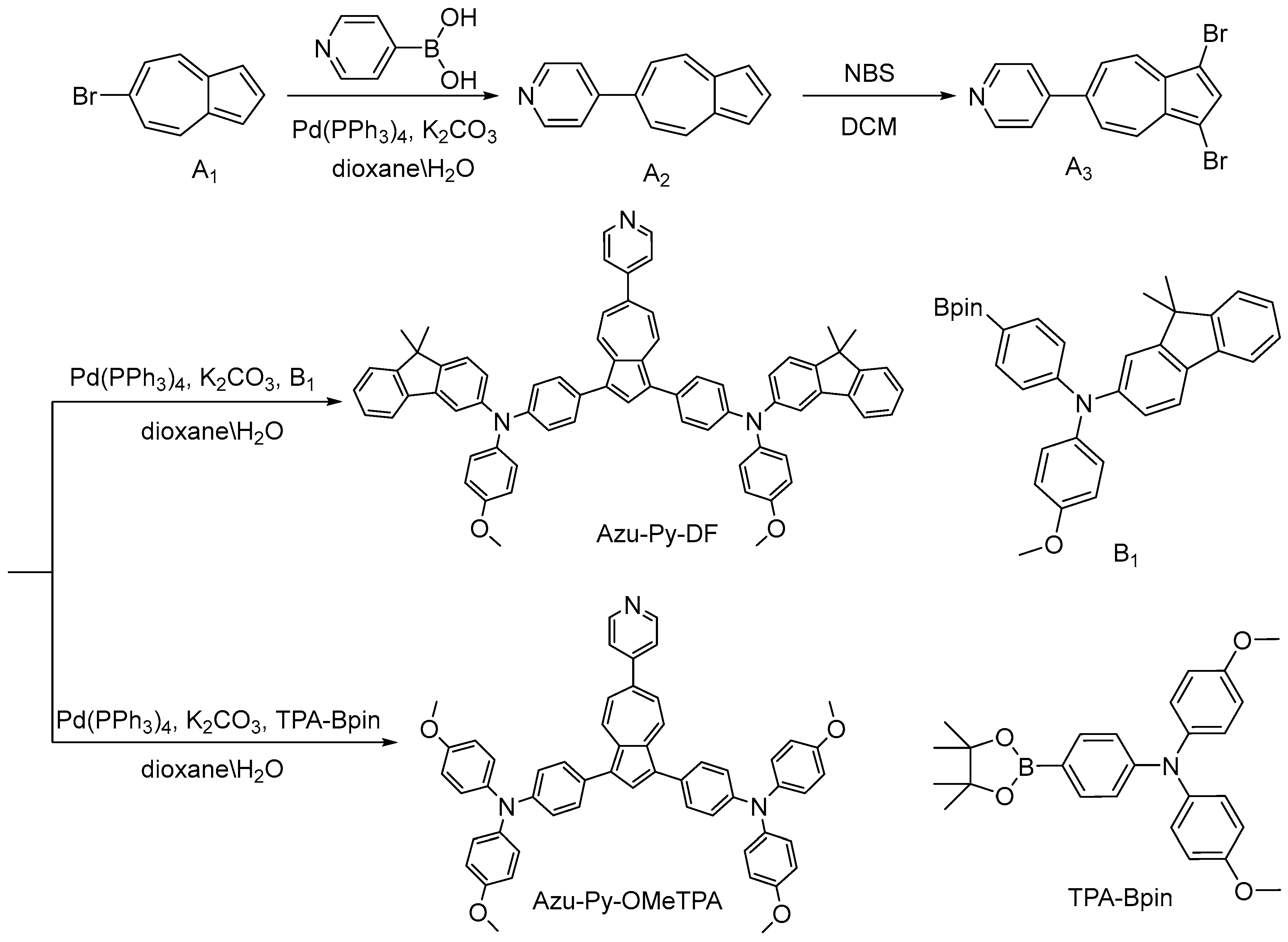
2.1. Synthesis and Characterization of HTMs
2.1.1. Synthesis of 6-(4-Pyridyl)Azulene (A2)
2.1.2. Synthesis of 1,3-Dibromo-[6-(4-Pyridyl)]Azulene (A3)
2.1.3. Synthesis of Azu-Py-DF
2.1.4. Synthesis of Azu-Py-OMeTPA
2.2. PSC Device Fabrication
3. Results and Discussion
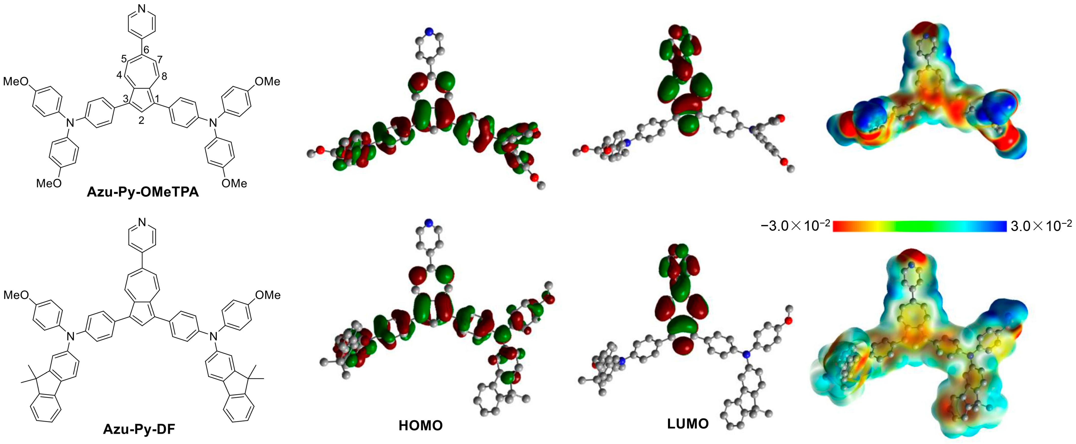
3.1. Design and Synthesis
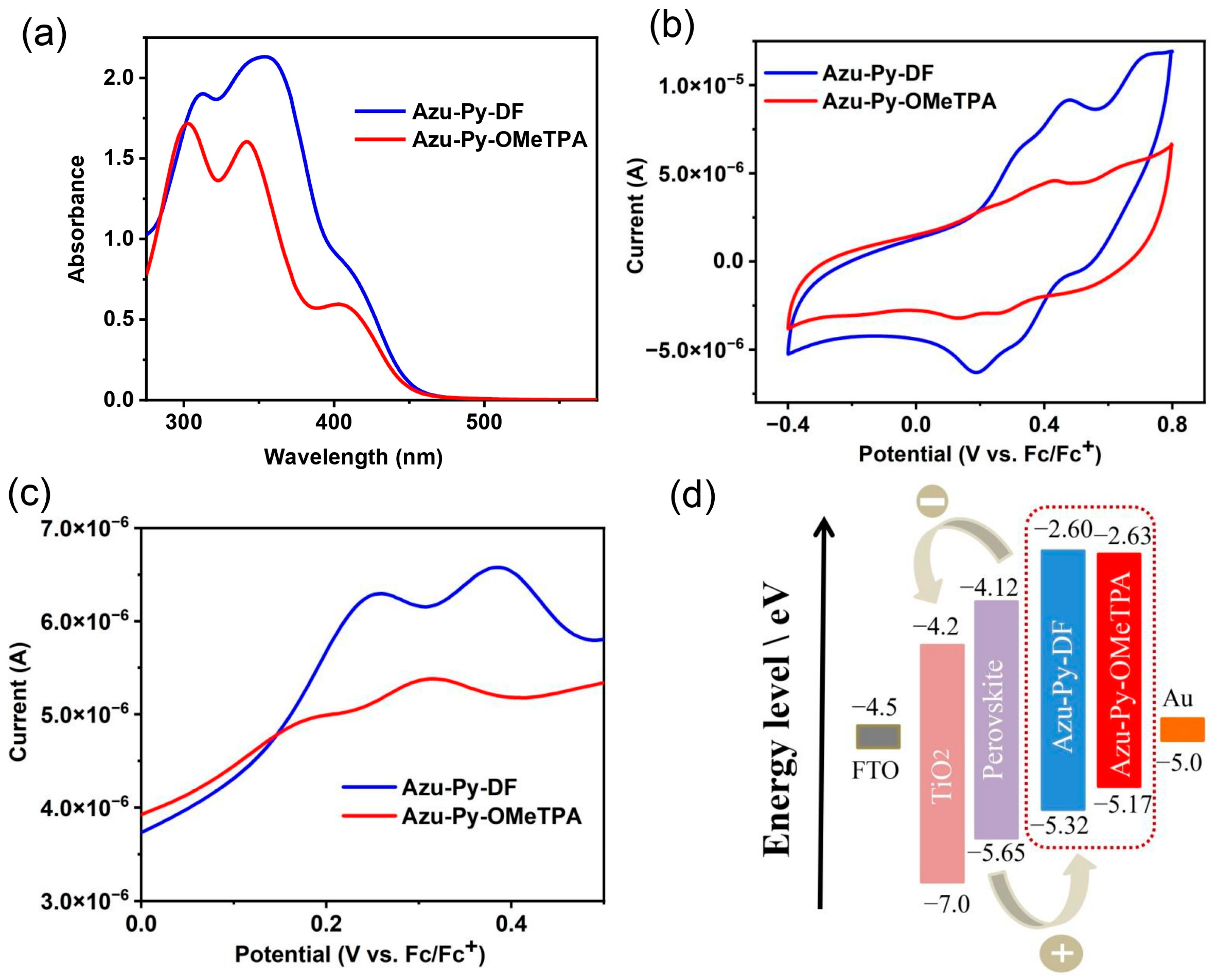
3.2. Photophysical and Electrochemical Properties
3.3. Photovoltaic Properties
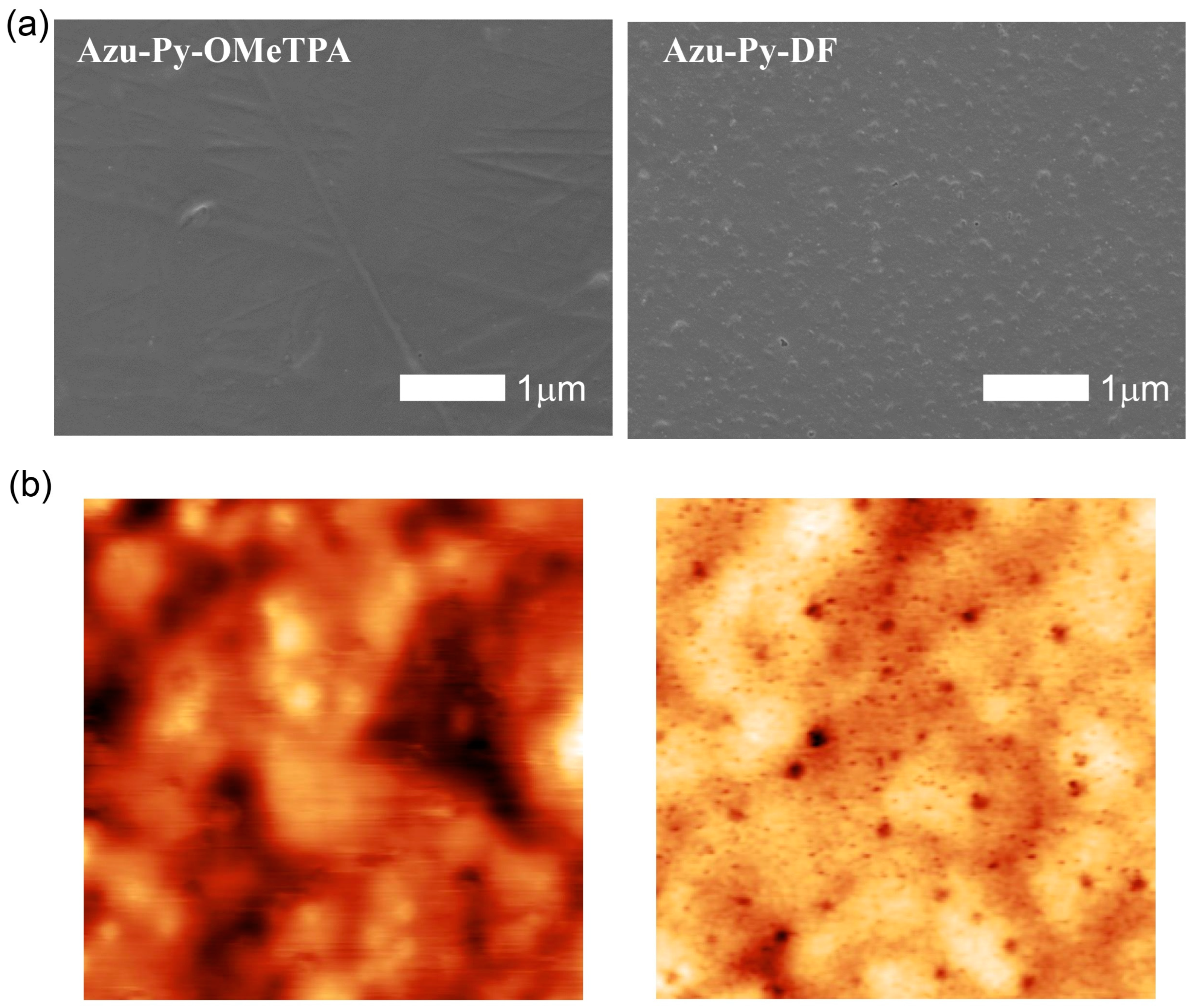
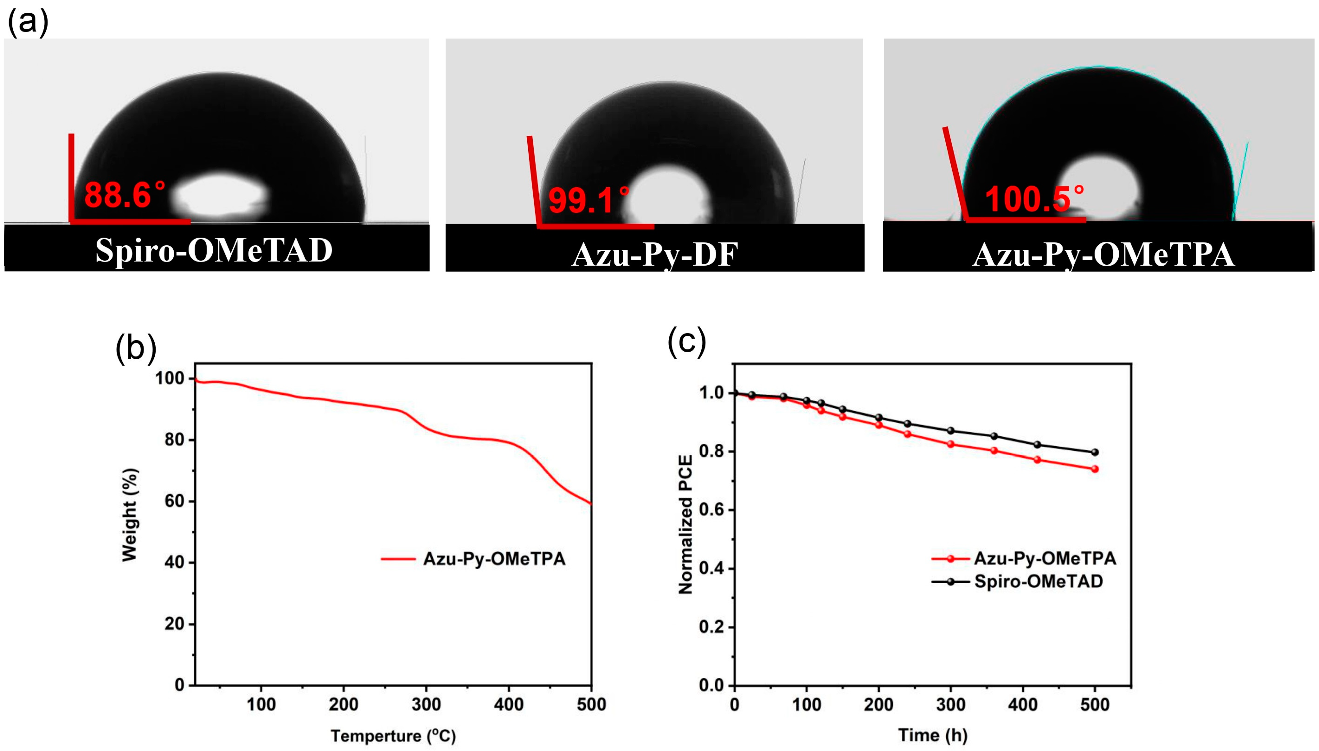
3.4. Surface Morphologies and Hydrophobicities
4. Conclusions
Supplementary Materials
Author Contributions
Funding
Institutional Review Board Statement
Informed Consent Statement
Data Availability Statement
Conflicts of Interest
References
- Kojima, A.; Teshima, K.; Shirai, Y.; Miyasaka, T. Organometal halide perovskites as visible-light sensitizers for photovoltaic cells. J. Am. Chem. Soc. 2009, 131, 6050–6051. [Google Scholar]
- Chen, H.; Liu, C.; Xu, J.; Maxwell, A.; Zhou, W.; Yang, Y.; Zhou, Q.; Bati, A.S.R.; Wan, H.; Wang, Z.; et al. Improved charge extraction in inverted perovskite solar cells with dual-site-binding ligands. Science 2024, 384, 189–193. [Google Scholar] [CrossRef] [PubMed]
- Liu, S.; Li, J.; Xiao, W.; Chen, R.; Sun, Z.; Zhang, Y.; Lei, X.; Hu, S.; Kober-Czerny, M.; Wang, F.; et al. Buried interface molecular hybrid for inverted perovskite solar cells. Nature 2024, 632, 536–542. [Google Scholar] [PubMed]
- Li, H.; Zhang, C.; Gong, C.; Zhang, D.; Zhang, H.; Zhuang, Q.; Yu, X.; Gong, S.; Chen, X.; Yang, J.; et al. 2D/3D heterojunction engineering at the buried interface towards high-performance inverted methylammonium-free perovskite solar cells. Nat. Energy 2023, 8, 946–955. [Google Scholar] [CrossRef]
- Liu, J.; He, Y.; Ding, L.; Zhang, H.; Li, Q.; Jia, L.; Yu, J.; Lau, T.W.; Li, M.; Qin, Y.; et al. Perovskite/silicon tandem solar cells with bilayer interface passivation. Nature 2024, 635, 596–603. [Google Scholar] [CrossRef]
- Yang, W.; Gao, M.; Zhang, Y.; Dai, Y.; Peng, W.; Ji, S.; Ji, Y.; Huang, W.; Xu, W. Self-driven photoelectrochemical sensor based on Z-type perovskite heterojunction for profenofos detection in milk and cabbage. J. Food Compos. Anal. 2024, 136, 106738. [Google Scholar]
- Ding, X.; Yan, M.; Chen, C.; Zhai, M.; Wang, H.; Tian, Y.; Wang, L.; Sun, L.; Cheng, M. Efficient and Stable Tin-Lead Mixed Perovskite Solar Cells Using Post-Treatment Additive with Synergistic Effects. Angew. Chem. Int. Ed. 2024, 63, e202317676. [Google Scholar] [CrossRef]
- He, W.; Liu, Y.; Sun, H.; Taghizadeh-Hesary, F. How does climate change affect rice yield in China? Agriculture 2020, 10, 441. [Google Scholar] [CrossRef]
- Chauhdary, J.N.; Li, H.; Akbar, N.; Javaid, M.; Rizwan, M.; Akhlaq, M. Evaluating corn production under different plant spacings through integrated modeling approach and simulating its future response under climate change scenarios. Agric. Water Manag. 2024, 293, 108691. [Google Scholar] [CrossRef]
- Nazir, M.J.; Li, G.; Nazir, M.M.; Zulfiqar, F.; Siddique, K.H.M.; Iqbal, B.; Du, D. Harnessing soil carbon sequestration to address climate change challenges in agriculture. Soil Till. Res. 2024, 237, 105959. [Google Scholar]
- Zhou, J.; Tan, L.; Liu, Y.; Li, H.; Liu, X.; Li, M.; Wang, S.; Zhang, Y.; Jiang, C.; Hua, R.; et al. Highly efficient and stable perovskite solar cells via a multifunctional hole transporting material. Joule 2024, 8, 1691–1706. [Google Scholar]
- Cheng, Q.; Chen, W.; Li, Y.; Li, Y. Recent Progress in Dopant-Free and Green Solvent-Processable Organic Hole Transport Materials for Efficient and Stable Perovskite Solar Cells. Adv. Sci. 2024, 11, 2307152. [Google Scholar]
- Hu, X.; Wang, L.; Luo, S.; Yan, H.; Chen, S. Polymeric Charge-Transporting Materials for Inverted Perovskite Solar Cells. Adv. Mater. 2024, 2412327. [Google Scholar] [CrossRef]
- Yu, X.; Sun, X.; Zhu, Z.; Li, Z. Stabilization Strategies of Buried Interface for Efficient SAM-Based Inverted Perovskite Solar Cells. Angew. Chem. Int. Ed. 2024, 64, e202419608. [Google Scholar]
- Zhai, M.; Li, M.; Deng, Z.; Yao, R.; Wang, L.; Cheng, C.; Wang, H.; Ding, X.; Liu, L.; Li, X.; et al. Perovskite Solar Cells and Modules Employing Facile Synthesis and Green-Solvent-Processable Organic Hole Transport Materials. ACS Energy Lett. 2023, 8, 4966–4975. [Google Scholar]
- Xia, Z.; Feng, X.; Wu, T.; Zhang, W.; Chen, C.; Wang, L.; Zhang, W.; Wang, H.; Tian, Y.; Yong, H.; et al. Dimeric Carbazole Core Based Dopant-Free Hole Transport Material for n-i-p Planar Perovskite Solar Cell. Adv. Funct. Mater. 2024, 34, 2408423. [Google Scholar]
- Zhang, X.; Liu, X.; Tirani, F.F.; Ding, B.; Chen, J.; Rahim, G.; Han, M.; Zhang, K.; Zhou, Y.; Quan, H.; et al. Dopant-Free Pyrene-Based Hole Transporting Material Enables Efficient and Stable Perovskite Solar Cells. Angew. Chem. Int. Ed. 2024, 63, e202320152. [Google Scholar]
- Wei, Y.; Cai, Y.; He, L.; Zhang, Y.; Yuan, Y.; Zhang, J.; Wang, P. Molecular engineering of nitrogen-rich helicene based organic semiconductors for stable perovskite solar cells. Chem. Sci. 2023, 14, 10285–10296. [Google Scholar]
- Peng, D.; Xia, Z.; Wang, H.; Chen, C.; Zhai, M.; Tian, Y.; Cheng, M. An efficient asymmetric structured hole transport material for perovskite solar cells. Chem. Comm. 2024, 60, 2665–2668. [Google Scholar]
- Man, M.; Zhao, M.; Lyu, Y. Hole-Transporting Materials Based on a Fluorene Unit for Efficient Optoelectronic Devices. Materials 2024, 17, 5417. [Google Scholar] [CrossRef]
- Castillo, C.; Aracena, A.; Ballesteros, L.; Neculqueo, G.; Gence, L.; Quero, F. New Benzotrithiophene-Based Molecules as Organic P-Type Semiconductor for Small-Molecule Organic Solar Cells. Materials 2023, 16, 3759. [Google Scholar] [CrossRef]
- Gao, H.; Yao, Y.; Li, C.; Zhang, J.; Yu, H.; Yang, X.; Shen, J.; Liu, Q.; Xu, R.; Gao, X.; et al. Fused Azulenyl Squaraine Derivatives Improve Phototheranostics in the Second Near-Infrared Window by Concentrating Excited State Energy on Non-Radiative Decay Pathways. Angew. Chem. Int. Ed. 2024, 63, e202400372. [Google Scholar]
- Xiang, J.; Vu, D.; He, M.; Duan, C.; Ge, C.; McNeill, C.R.; Gao, X. Poly (2, 6-azulene vinylene) s: Azulene Orientation Control and Property Studies. Macromolecules 2023, 56, 9475–9488. [Google Scholar]
- Xiang, J.; Tan, W.L.; Zhang, J.; Wang, Y.; Duan, C.; McNeill, C.R.; Yang, X.; Ge, C.; Gao, X. Poly (2, 6-azuleneethynylene) s: Design, Synthesis, and Property Studies. Macromolecules 2022, 55, 8074–8083. [Google Scholar]
- Xin, H.; Ge, C.; Jiao, X.; Yang, X.; Rundel, K.; McNeill, C.R.; Gao, X. Incorporation of 2, 6-connected azulene units into the backbone of conjugated polymers: Towards high-performance organic optoelectronic materials. Angew. Chem. Int. Ed. 2018, 57, 1322–1326. [Google Scholar]
- Nishimura, H.; Ishida, N.; Shimazaki, A.; Wakamiya, A.; Saeki, A.; Scott, L.T.; Murata, Y. Hole-transporting materials with a two-dimensionally expanded π-system around an azulene core for efficient perovskite solar cells. J. Am. Chem. Soc. 2015, 137, 15656–15659. [Google Scholar]
- Truong, M.A.; Lee, J.; Nakamura, T.; Seo, J.Y.; Jung, M.; Ozaki, M.; Shimazaki, A.; Shioya, N.; Hasegawa, T.; Murata, Y.; et al. Influence of Alkoxy Chain Length on the Properties of Two-Dimensionally Expanded Azulene-Core-Based Hole-Transporting Materials for Efficient Perovskite Solar Cells. Chem. Eur. J. 2019, 25, 6741–6752. [Google Scholar]
- Tzoganakis, N.; Feng, B.X.; Loizos, M.; Krassas, M.; Tsikritzis, D.; Zhuang, X.D.; Kymakis, E. Ultrathin PTAA interlayer in conjunction with azulene derivatives for the fabrication of inverted perovskite solar cells. J. Mater. Chem. C 2021, 9, 14709–14719. [Google Scholar]
- Li, H.; Wang, Z.; Sun, Y.; Su, Y.; Zhao, Z.; Tian, Y.; Li, H.; Cheng, M. Peripheral substituent regulation of bias structured azulene-based hole transport materials for perovskite solar cells. New J. Chem. 2023, 47, 19057–19062. [Google Scholar]
- Su, Y.; Li, H.; Miao, Y.; Tian, Y.; Cheng, M. Azulene-based Hole Transport Materials with Proper Electronic Properties for Perovskite Solar Cells. Asian J. Org. Chem. 2022, 11, e202200441. [Google Scholar]
- Liu, C.; Huang, G.; Zhai, M.; Yang, Y.; Wang, H.; Chen, C.; Zhao, G.; Zhang, W.; Yan, M.; Cheng, M. Pyridine-Anchored Small Molecule Interlayer Enables Defect Passivation and Enhanced Carrier Transport for Perovskite Solar Cells. J. Phys. Chem. Lett. 2024, 15, 8949–8955. [Google Scholar] [PubMed]
- Cariello, M.; Pant, N.; Harkiss, A.H.; Tracey, F.M.; Cameron, J.; Skabara, P.J.; Holliman, P.J.; Docampo, P.; Cooke, G. Synthesis of SOT-OH and its application as a building block for the synthesis of new dimeric and trimeric Spiro-OMeTAD materials. Mol. Syst. Des. Eng. 2022, 7, 899–905. [Google Scholar]


| HTM | λabs (nm) | Eg (eV) | HOMO (eV) | LUMO (eV) | Hole Mobility (cm2 V−1 S−1) | Conductivity (S cm−1) |
|---|---|---|---|---|---|---|
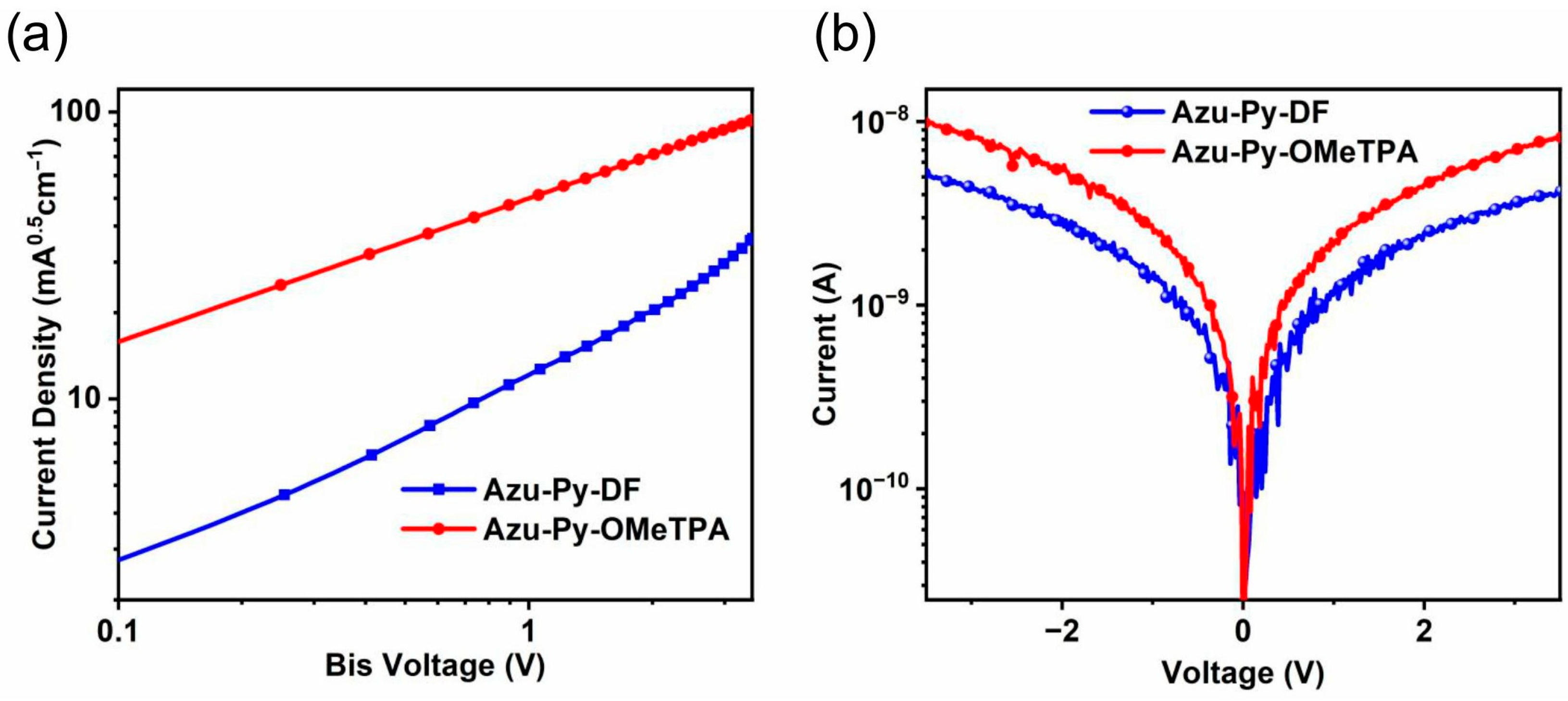
| Azu-Py-DF | 413 | 2.72 | −5.32 | −2.60 | 3.16 × 10⁻⁵ | 2.60 × 10⁻⁵ |
| Azu-Py-OMeTPA | 404 | 2.54 | −5.17 | −2.63 | 1.47 × 10⁻⁴ | 5.01 × 10⁻⁵ |
| Spiro-OMeTAD [30] | 386 | 2.99 | −5.09 | −2.10 | 1.86 × 10⁻⁴ | 7.38 × 10⁻⁵ |
| HTM | Voc (V) | Jsc (mA cm−2) | FF (%) | PCE (%) | Jsccal (mA cm−2) |
|---|---|---|---|---|---|
| Azu-Py-OMeTPA | 1.04 | 24.48 | 71.42 | 18.10 | 24.03 |
| Azu-Py-DF | 0.91 | 23.97 | 70.68 | 15.39 | 22.79 |
| Spiro-OMeTAD [30] | 1.03 | 25.47 | 76.06 | 20.00 | 24.28 |
Disclaimer/Publisher’s Note: The statements, opinions and data contained in all publications are solely those of the individual author(s) and contributor(s) and not of MDPI and/or the editor(s). MDPI and/or the editor(s) disclaim responsibility for any injury to people or property resulting from any ideas, methods, instructions or products referred to in the content. |
© 2025 by the authors. Licensee MDPI, Basel, Switzerland. This article is an open access article distributed under the terms and conditions of the Creative Commons Attribution (CC BY) license (https://creativecommons.org/licenses/by/4.0/).
Share and Cite
Sun, Y.; Wang, Z.; Geng, T.; Liu, X.; Su, Y.; Tian, Y.; Cheng, M.; Li, H. 6-(4-Pyridyl)Azulene Derivatives as Hole Transport Materials for Perovskite Solar Cells. Materials 2025, 18, 1400. https://doi.org/10.3390/ma18071400
Sun Y, Wang Z, Geng T, Liu X, Su Y, Tian Y, Cheng M, Li H. 6-(4-Pyridyl)Azulene Derivatives as Hole Transport Materials for Perovskite Solar Cells. Materials. 2025; 18(7):1400. https://doi.org/10.3390/ma18071400
Chicago/Turabian StyleSun, Yuanqing, Zhangyan Wang, Tianyi Geng, Xinyue Liu, Yangyang Su, Yi Tian, Ming Cheng, and Hongping Li. 2025. "6-(4-Pyridyl)Azulene Derivatives as Hole Transport Materials for Perovskite Solar Cells" Materials 18, no. 7: 1400. https://doi.org/10.3390/ma18071400
APA StyleSun, Y., Wang, Z., Geng, T., Liu, X., Su, Y., Tian, Y., Cheng, M., & Li, H. (2025). 6-(4-Pyridyl)Azulene Derivatives as Hole Transport Materials for Perovskite Solar Cells. Materials, 18(7), 1400. https://doi.org/10.3390/ma18071400