Redesign of a Flange Wheel Used in an Airplane for Composite Manufacturing Made with a Mold with Removable Inserts Manufactured by Means of 3D Printing: A Comparison with the Current Conventional Alternative, a Turbine Wheel Machined out of Aluminum
Abstract
1. Introduction
2. Materials and Methods
- Redesign of the aluminum part to be able to be manufactured with plastic materials.
- Design of the mold to produce the redesigned part.
- Validation of real plastic parts by means of tomography.
2.1. Redesign of Parts in Plastic Materials
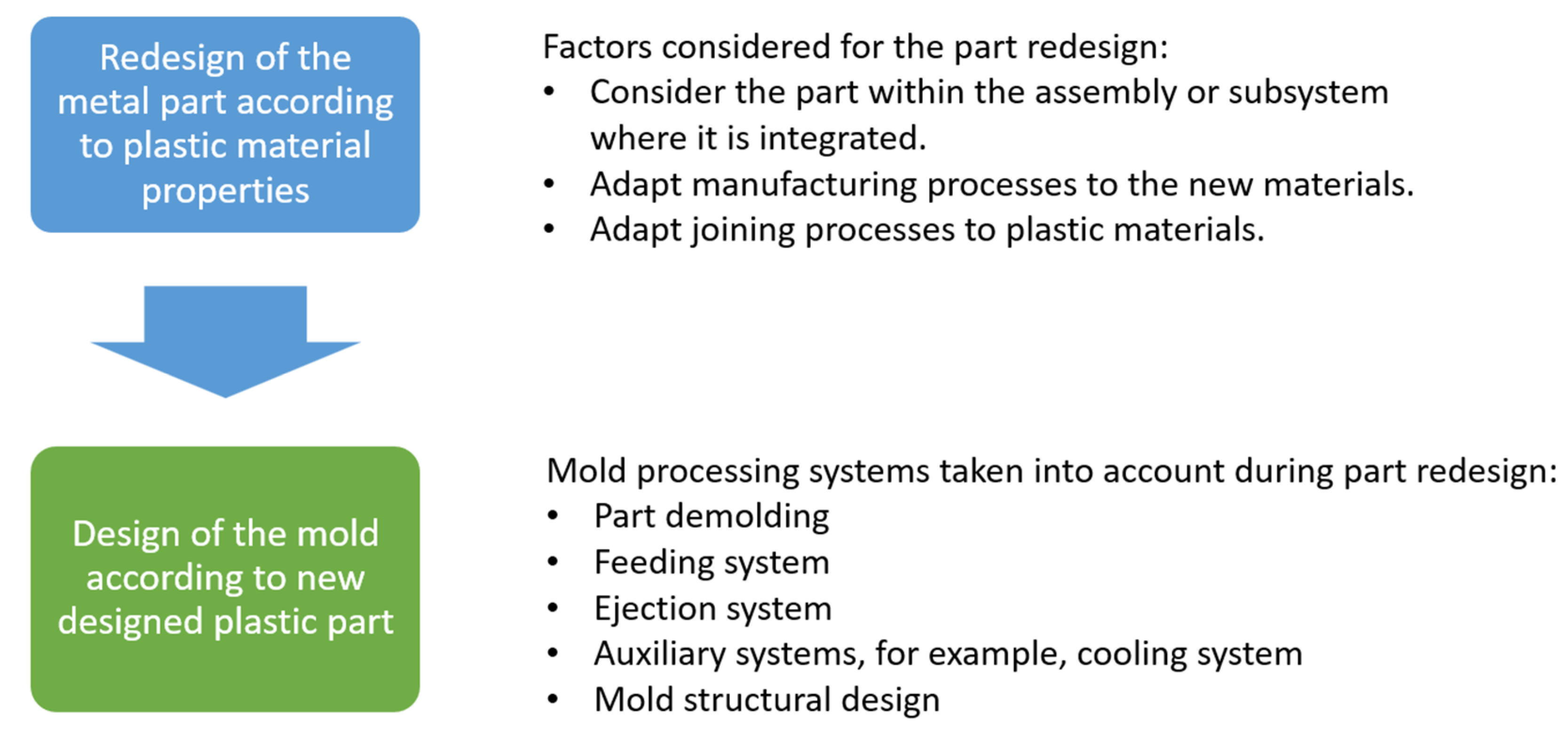
- Consider redesigning not just the part but also the assembly or subsystem it integrates with: This means avoiding a simple one-to-one substitution of the material without rethinking the design. Instead, the goal should be to maintain the part’s functionality while reshaping it to generate new functionalities that add more value to the redesigned part. The transformation processes for plastic materials enable the creation of complex shapes without increasing costs. These complex shapes can enhance the functionality of parts and even reduce the number of components by combining several elements from the original design into a single plastic part. Achieving a reduction in the number of parts during the redesign process can lower assembly costs, reduce the number of part references, and simplify the mechanical assembly.
- Adapt manufacturing processes to the new materials: Many manufacturing processes applied to traditional materials can also be used for plastics [18]. However, plastics have unique processes that offer numerous advantages. For instance, injection molding in its various forms allows for thermoplastic manufacturing with the following features:
- Fast and economical production processes.
- Feasibility for both large and small production runs.
- Complex shapes without added costs.
- Variability in aesthetic finishes, surface treatments, and part marking at minimal additional cost.
- Possibility for post-process operations such as machining, finishing, and painting.
- Adapt joining processes to plastic materials: The joining processes for plastic parts must consider the characteristics of the materials and their manufacturing methods. This includes incorporating joining techniques such as overmolding, adjusting design criteria for traditional methods like screwing, clamping, and riveting, simplifying processes like snap-fits or welding, and, in some cases, complicating others like adhesive bonding. In general, special care must be taken when designing joints to account for the properties of the materials and how they respond to the types of stresses and environments in which they will operate.
2.2. Mold Design
- Part demolding: When defining the geometry of a part to be manufactured using an injection mold, it is crucial to consider how the part will be demolded and separated from the mold. Some parts naturally demold, but many others have undercuts. For these undercuts, demolding systems must be designed to make manufacturing the part viable. It is also necessary to define the areas requiring draft angles, determine the appropriate draft values, and assess whether these angles impact the part’s functionality.
- Feed system: This system ensures that the mold is filled properly. It influences several factors, such as the mold’s ability to fill, the geometry of the finished part, and its aesthetic and mechanical quality. The design of the feed system affects how material flows within the mold and all related aspects, such as part shrinkage and material orientation.
- Ejection system: As the material cools down inside the mold, it contracts, causing the part to shrink. The mold prevents the part from shrinking in certain dimensions during contraction, leading the part to adhere to specific sections of the mold. Mold design must anticipate where the part will remain attached and include a system to separate the part from the mold in that area. This system will operate after the mold opens and must remove the part without damaging it.
- Auxiliary systems: Various auxiliary systems ensure the mold functions correctly. For example, the cooling system ensures rapid and uniform part cooling. The guidance and centering system ensures that when the mold closes, all its components align correctly to define the part’s geometry. Other auxiliary systems might include elements for mold handling and transportation, parameter recording, and more.
- Mold structural design: The mold is a component subjected to fatigue, undergoing significant pressure, force, and temperature variations in short cycles. For instance, during each cycle, the mold is compressed with the clamping force to prevent it from opening during injection, and the cavity endures extremely high pressures. Thin or large parts made from viscous materials may require injection pressures exceeding 1e8 (Pa). To ensure the mold endures many cycles, the selection of materials, structural element dimensions, plate thicknesses, and component assembly must be carefully designed. Proper joint and alignment designs for all components are also critical.
2.3. Tomography as a System for Part Verification
3. Case Study
3.1. Turbine Wheel: Introduction to the Part
3.2. INNPAEK Turbine: Redesign of the Turbine for Manufacturing with Removable Insert Molds: Introduction to the Part
3.3. INNPAEK Turbine Manufacturing and Validation of Manufacturing Process
4. Results and Discussion
4.1. Mold with Salt and 3D-Printed Inserts
4.2. Part with Core Manufactured by 3D Printing vs. Aluminum
4.3. Geometrical Analysis of the Part
5. Conclusions
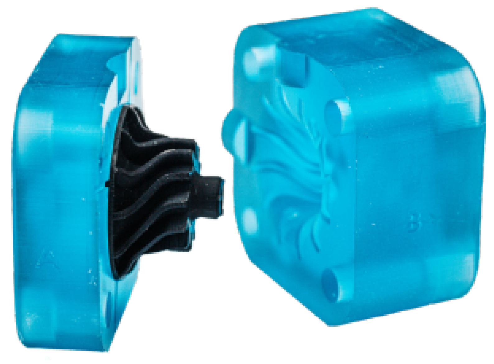
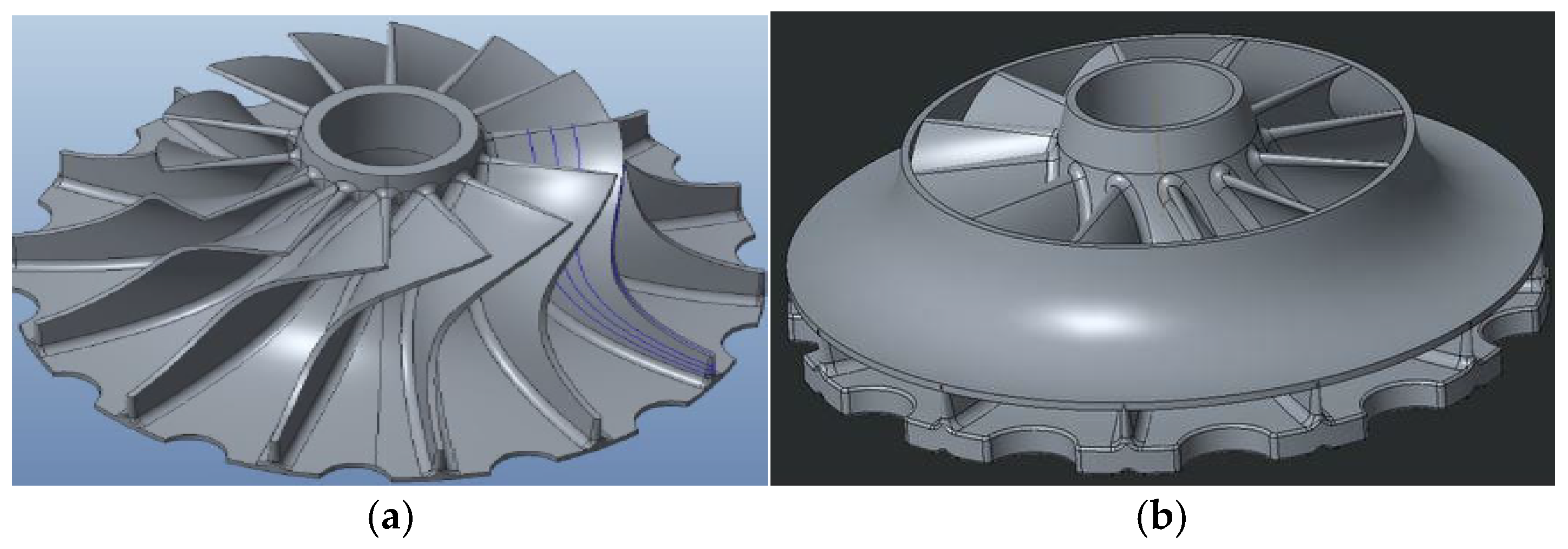
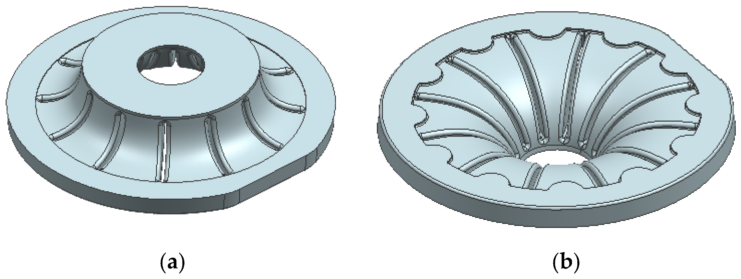
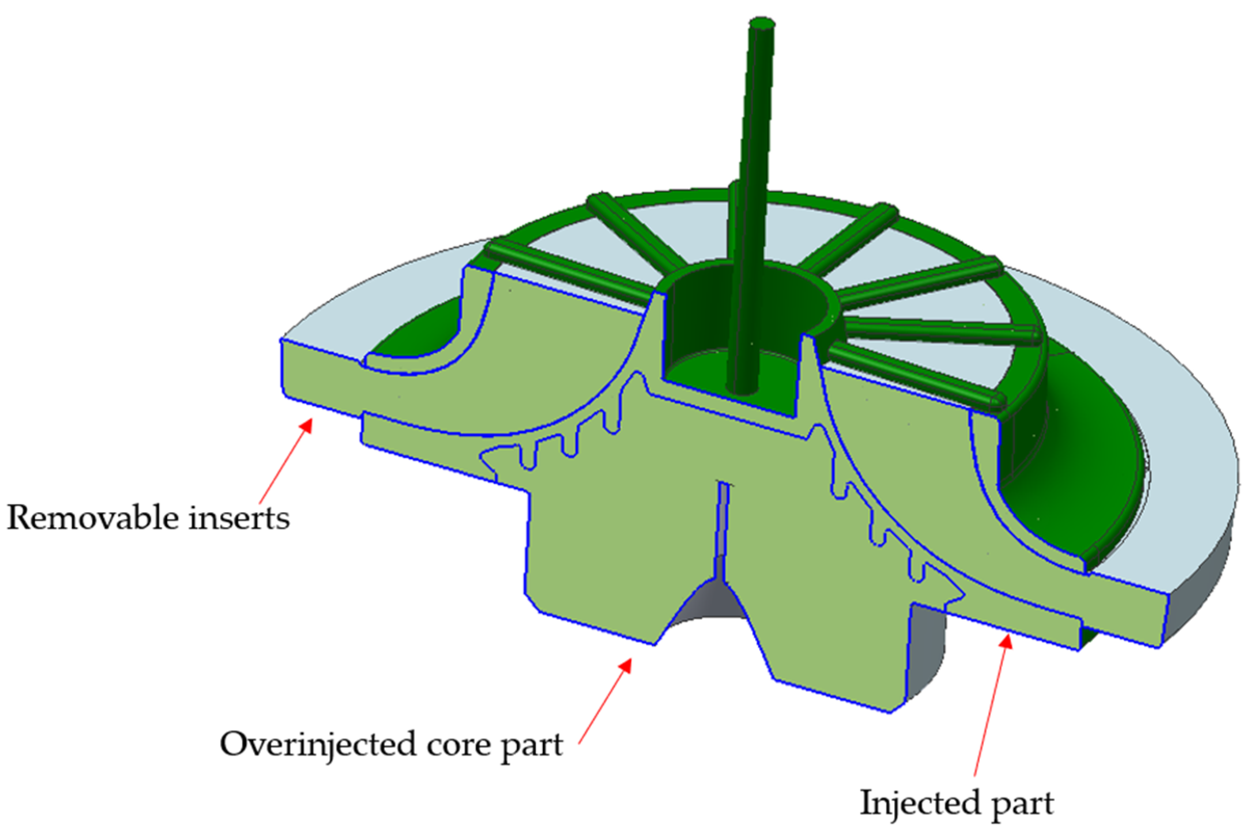
- Additive manufacturing technology has been applied for the redesign of an aluminum part into a plastic one. On the one hand, additive technology was used to produce removable inserts for complex cavities production, and on the other hand, to produce a thick core part to be overinjected, made of plastic, optimizing its weight compared with the aluminum solution.
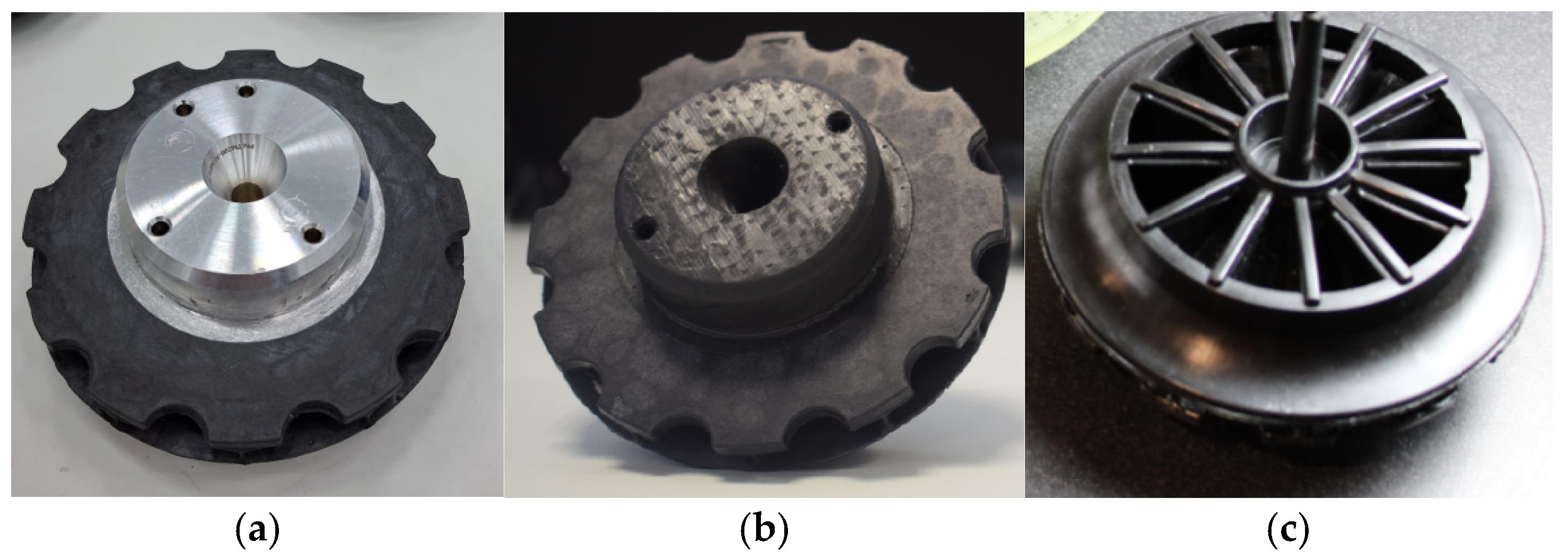
- An injection mold was produced, using 3D-printed removable inserts, in combination with a core part to be overinjected, producing plastic wheels both with aluminum and 3D-printed cores.
- Lighter parts were obtained, thanks on one side to the redesign of the part with plastic, possible due to the 3D-printed removable inserts, and on the other side, thanks to the use of additive manufacturing technology to the production of the core part in plastic, lighter than the aluminum core and only feasible to be produced in plastic with this kind of printing technology.
Author Contributions
Funding
Institutional Review Board Statement
Informed Consent Statement
Data Availability Statement
Conflicts of Interest
References
- Steineger, R. Fuel Economy for Aircraft Operation as a Function of Weight and Distance; ZHAW Zürcher Hochschule Für Angewandte Wissenschaften: Winterthur, Switzerland, 2017. [Google Scholar] [CrossRef]
- Léonard, P.L.Y.; Nylander, J.W. Sustainability Assessment of Composites in Aero-Engine Components. International Design Conference—Design 2020; Cambridge University Press: Cambridge, UK, 2020. [Google Scholar] [CrossRef]
- Zhang, L.; Wnag, X.; Pei, J.; Zhou, Y. Review of automated fibre placement and its prospects for advanced composites. J. Mater. Sci. 2020, 55, 7121–7155. [Google Scholar] [CrossRef]
- Ghory, S.; Siakeng, R.; Rasheed, M.; Saba, N.; Jawaid, M. The role of advanced polymer materials in aerospace. In Sustainable Composites for Areospace Applications; Woodhead Publishing: Sawston, UK, 2018; pp. 19–34. [Google Scholar] [CrossRef]
- Minamisawa, T. Investigation of CFRP in aerospace field and improvement of the molding accuracy by using autoclave. In Proceeding of the 3rd International Conference of Global Network for Innovative Technology, Penang, Malaysia, 27–29 January 2016. [Google Scholar] [CrossRef]
- Trotignon, J.P.; Verdu, J.; Dobraozynski, A.; Piperaud, M. Précis de Matières Plastiques AFNOR-NATHAN Livre de L’élève. 2023. Available online: https://www.fnac.com/a1798375/Alexandre-Dobraczynski-Precis-de-matieres-plastiques-AFNOR-NATHAN-Livre-de-l-eleve (accessed on 1 February 2021).
- Ceramtec Webpage. CeramTec Subsidiary Emil-Müller. Available online: https://www.ceramtec-group.com/de/emil-mueller (accessed on 1 March 2021).
- Guo, N.; Leu, M. Additive manufacturing: Technology, applications and research needs. Front. Mech. Eng. 2013, 8, 215–243. [Google Scholar] [CrossRef]
- Tadini, P.; Grange, N.; Chetehouna, K.; Gascoin, N.; Senave, S.; Reynaud, I. Thermal degradation análisis of innovative PEKK-based carbon composites for high-temperature aeronautical components. Aerosp. Sci. Technol. 2017, 65, 106–116. [Google Scholar] [CrossRef]
- Clean Aviation Webpage. Available online: https://www.clean-aviation.eu/peek-performance-delivers-positive-outcome (accessed on 1 March 2021).
- Anurag, S. Carbon fiber-reinforced PEEK polymer composites as a futuristic material for aircraft structures. Researchgate 2022, 7. [Google Scholar] [CrossRef]
- Sun, X.; Tan, Y.; Li, X.; Ding, C.; Hu, Q. The effect of downhole turbine modelling parameters on mechanical output performance. Processes 2025, 13, 507. [Google Scholar] [CrossRef]
- Magazzù, A.; Marcuello, C. Investigation of soft matter nanomechanics by atomic force microscopy and optical tweezers: A comprehensive review. Nanomaterials 2023, 13, 963. [Google Scholar] [CrossRef] [PubMed]
- Nexa3D Webpage. Available online: https://nexa3d.com/materials/ (accessed on 1 March 2021).
- Javierre, C.; Abad, J.; Camañes, V.; Franch, D. Redesign of metallic parts with thermoplastic materials: Application Excample. DYNA 2013, 88, 197–205. [Google Scholar] [CrossRef][Green Version]
- Javierre, C.; Fernández, A. Criterios de Diseño Mecánico en Tecnologías Industrials, 1st ed.; Prensas Universitarias de Zaragoza: Zaragoza, Spain, 2012; ISBN 978-84-15274-53-7. [Google Scholar]
- Aisa, J.; Javierre, C.; De la Serna, J.A. An example of simulation tolos use for large injection moulds design: The CONTENURTM 2400 l solid waste container. J. Mater. Process. Technol. 2006, 175, 15–19. [Google Scholar] [CrossRef]
- Liebsch, A.; Kupfer, R.; Krahl, M.; Haider, D.R.; Koshukow, W.; Gude, M. Adhesion studies of thermoplastic fibre-plastic composite hybrid components Part 1: Thermoplastic-Thermoplastic-Composites. Proc. Hybrid Mater. Struct. Germany 2018, 18–19. [Google Scholar]
- Kaufmann, R.; Bürkle, E.; Bider, T. Process Integration—Lightweight Parts with a Thermoplastic Matrix. Kunstoffe Int. 2011, 3, 65–68. [Google Scholar]
- Cardozo, D. A brief history of the filling simulation of injection moulding. Proc. Inst. Mech. Eng. Part C J. Mech. Eng. Sci. 2009, 223, 711–721. [Google Scholar] [CrossRef]
- Cuello, A.F.; Peinado, V. Software as Kommunikations plattform. Kunststoffe 2009, 99, 48–51. [Google Scholar]
- Nguyen, Q.; Babanezhad, M.; Nakhjiri, A.T.; Rezakazemi, M.; Shirazian, S. Prediction of thermal distribution and fluid flow in the domain with multi-solid structures using Cubic-Interpolated Pseudo-Particle model. PLoS ONE 2020, 15, e0233850. [Google Scholar] [CrossRef] [PubMed]
- Gordon, M.J., Jr. Chapter 8—Six Sigma Keys to Success are Control, Capability and Repeatability. In Six Sigma Quality for Business and Manufacture; Elsevier Science B.V.: Amsterdam, The Netherland, 2002; pp. 333–392. [Google Scholar]
- Shi, H.; Xie, S.; Wang, X. A warpage optimization method for injection molding using artificial neural network with parametric sampling evaluation strategy. Int. J. Adv. Manuf. Technol. 2012, 65, 343–3523. [Google Scholar] [CrossRef]
- Salunke, M.; Kate, R.; Lomate, V.; Sopal, G. Injection Molding Methods Design, Optimization, Simulation of Plastic Toy Building Block by Mold Flow Analysis. Int. J. Mech. Eng. Technol. 2015, 6, 33–42. [Google Scholar]
- Ali, M.A.M.; Idayu, N.; Aziz, M.S.A.; Hadzley, M. Optimization of process parametersin linear runner family injection mold using mold flow simulation software. ARPN J. Eng. Appl. Sci. 2016, 11, 2475–2482. [Google Scholar]
- Filz, P.; Kutschera, H.; Stöckmann, H.; Welter, F.; Roetgen, K. Simulation of Fluid Flow and Structural Analysis within Thin Walled Three Dimensional Geometries. EP 1 385 103 A1, 28 January 2004.
- Osswald, T.A.; Rudolph, N. Polymer rheology. In Fundamentals and Applications; Hanser Publications: Cincinnati, OH, USA, 2015. [Google Scholar]
- Karrenberg, G.; Neubrech, B.; Wortberg, J. CFD-Simulation der Kunststoffplastifizierung in einem Extruder mit durchgehend genutetem Zylinder und Barriereschnecke. Z. Kunststofftechnik. 2013, 12, 205–238. [Google Scholar] [CrossRef]
- Nielsen, L.E.; Landel, R.F. Mechanical Properties of Polymers and Composites; Marcel Dekker: New York, NY, USA, 1994. [Google Scholar]
- Schmidt, T.W. Zur Abschätzung der Schwindung. Ph.D. Thesis, Rheinisch-Westfälische Technische Hochschule Aachen, Aachen, Germany, 1986. [Google Scholar]
- Airbus Webpage. Future Materials. Available online: https://www.airbus.com/en/innovation/future-aircraft/future-materials (accessed on 1 March 2025).
- Airbus Webpage. Fantastic Thermoplastics. Available online: https://www.airbus.com/en/newsroom/stories/2025-01-fantastic-thermoplastics (accessed on 1 March 2025).










| Result | Value |
|---|---|
| Optimized melt temperature (°C) | 380 |
| Optimized mold temperature (°C) | 190 |
| Optimized post-filling pressure (Bar) | 700 |
| Optimized filling time (s) | 0.62 |
| Optimized post-filling time (s) | 3.3 |
| Optimized cooling time (s) | 7.1 |
| Optimized cycle time (s) | 28.4 |
| Max. required pressure (Bar) | 612.5 |
| Min. flow front temp. (°C) | 351.3 |
| Max. shear stress (MPa) | 2.0 |
| Volumetric shrinkage variation (%) | 3.6 |
| Original | New Turbine Option 1 | New Turbine Option 2 | ||||
|---|---|---|---|---|---|---|
| Part | Material | Weight (g) | Material | Weight (g) | Material | Weight (g) |
| Flange Wheel | Aluminum | 287 | PEEK | 86.2 | PEEK | 86.2 |
| Core | Aluminum | 179 | X-PEEK | 92.8 | ||
| Total | 287 | 264.2 | 179 | |||
Disclaimer/Publisher’s Note: The statements, opinions and data contained in all publications are solely those of the individual author(s) and contributor(s) and not of MDPI and/or the editor(s). MDPI and/or the editor(s) disclaim responsibility for any injury to people or property resulting from any ideas, methods, instructions or products referred to in the content. |
© 2025 by the authors. Licensee MDPI, Basel, Switzerland. This article is an open access article distributed under the terms and conditions of the Creative Commons Attribution (CC BY) license (https://creativecommons.org/licenses/by/4.0/).
Share and Cite
Javierre, C.; Camañes, V.; Vidal, J.; Dieste, J.A.; Fernandez, A. Redesign of a Flange Wheel Used in an Airplane for Composite Manufacturing Made with a Mold with Removable Inserts Manufactured by Means of 3D Printing: A Comparison with the Current Conventional Alternative, a Turbine Wheel Machined out of Aluminum. Materials 2025, 18, 1296. https://doi.org/10.3390/ma18061296
Javierre C, Camañes V, Vidal J, Dieste JA, Fernandez A. Redesign of a Flange Wheel Used in an Airplane for Composite Manufacturing Made with a Mold with Removable Inserts Manufactured by Means of 3D Printing: A Comparison with the Current Conventional Alternative, a Turbine Wheel Machined out of Aluminum. Materials. 2025; 18(6):1296. https://doi.org/10.3390/ma18061296
Chicago/Turabian StyleJavierre, Carlos, Víctor Camañes, Julio Vidal, José Antonio Dieste, and Angel Fernandez. 2025. "Redesign of a Flange Wheel Used in an Airplane for Composite Manufacturing Made with a Mold with Removable Inserts Manufactured by Means of 3D Printing: A Comparison with the Current Conventional Alternative, a Turbine Wheel Machined out of Aluminum" Materials 18, no. 6: 1296. https://doi.org/10.3390/ma18061296
APA StyleJavierre, C., Camañes, V., Vidal, J., Dieste, J. A., & Fernandez, A. (2025). Redesign of a Flange Wheel Used in an Airplane for Composite Manufacturing Made with a Mold with Removable Inserts Manufactured by Means of 3D Printing: A Comparison with the Current Conventional Alternative, a Turbine Wheel Machined out of Aluminum. Materials, 18(6), 1296. https://doi.org/10.3390/ma18061296


