
Isothermal and Thermomechanical Fatigue Behavior of 316LN Stainless Steel Under Torsional Loading

Abstract
1. Introduction
2. Materials and Methods
2.1. Specimen
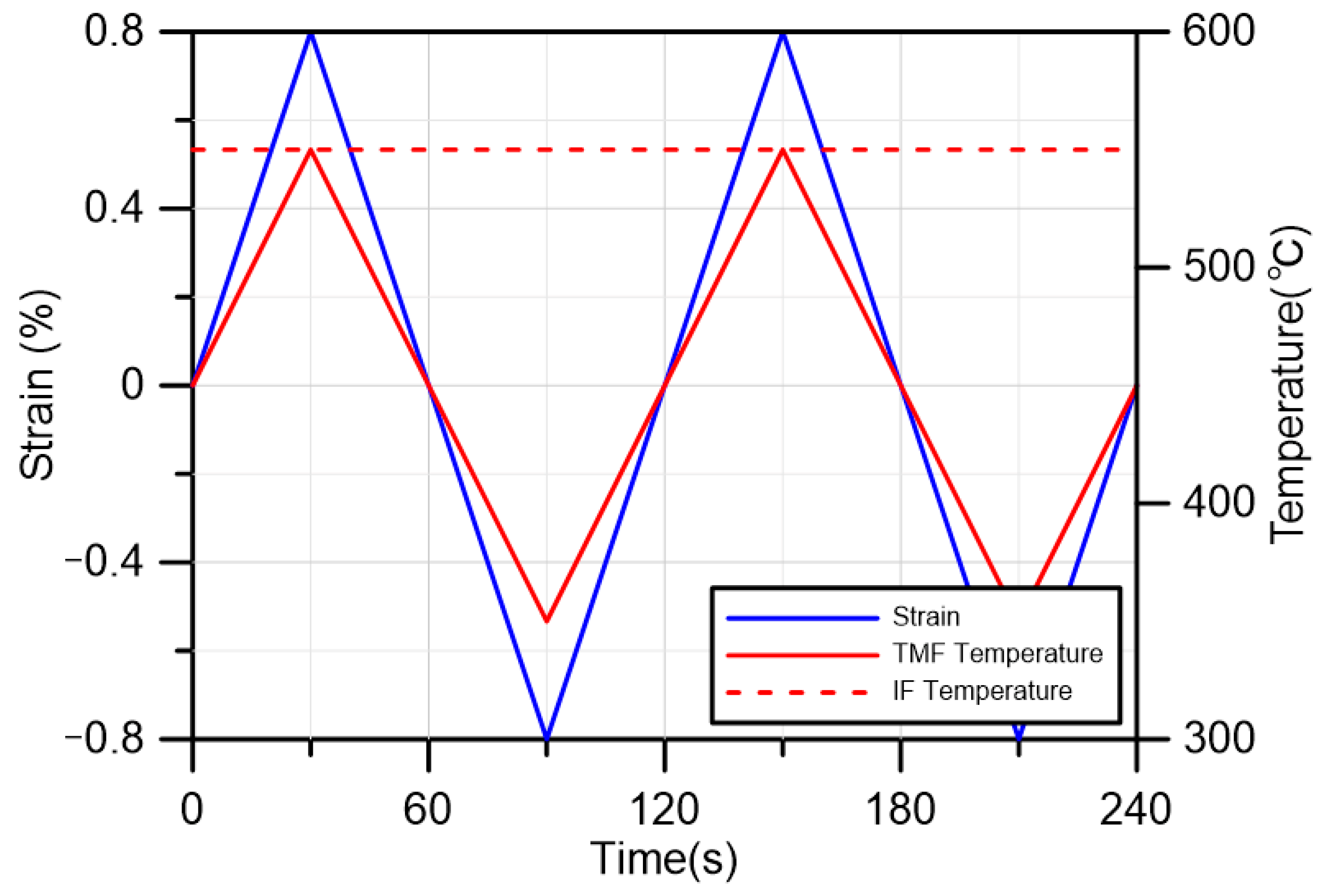
2.2. Test Details
3. Results and Discussion
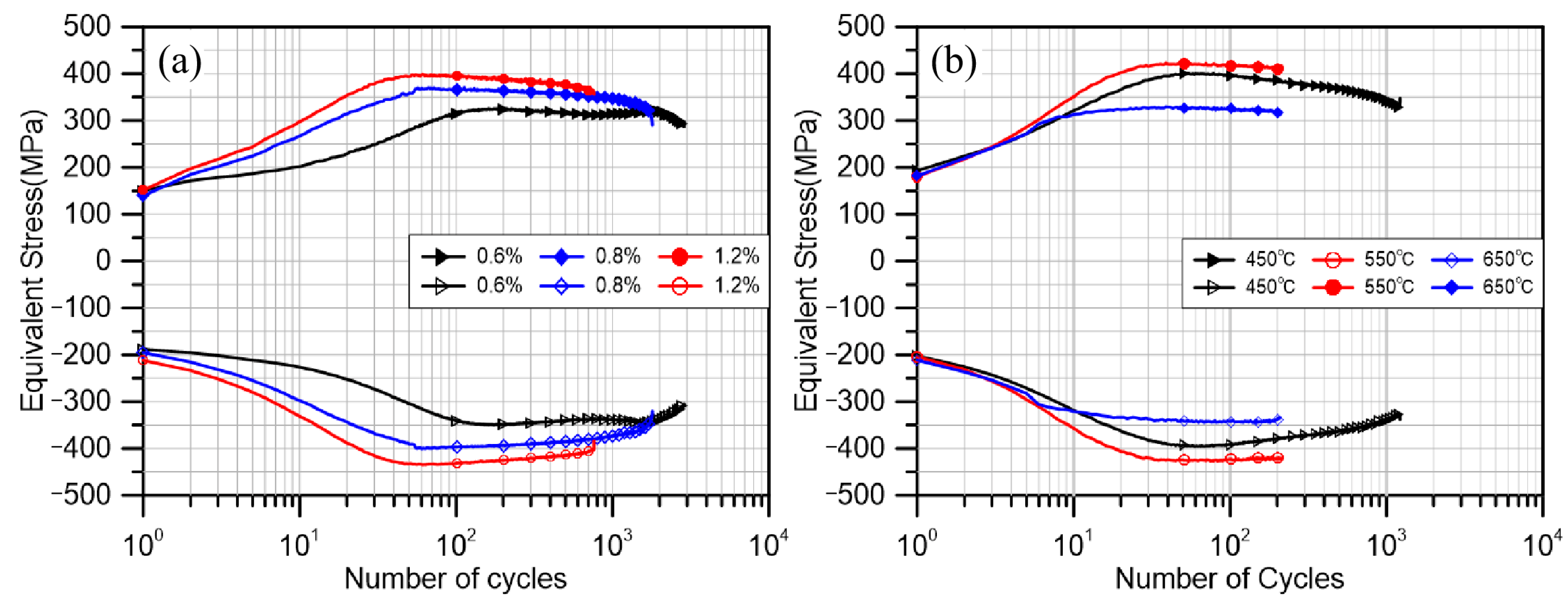
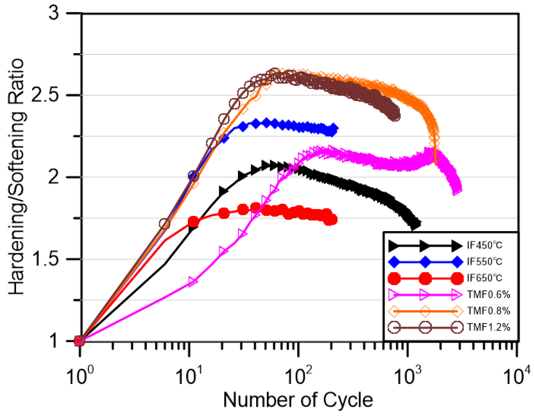
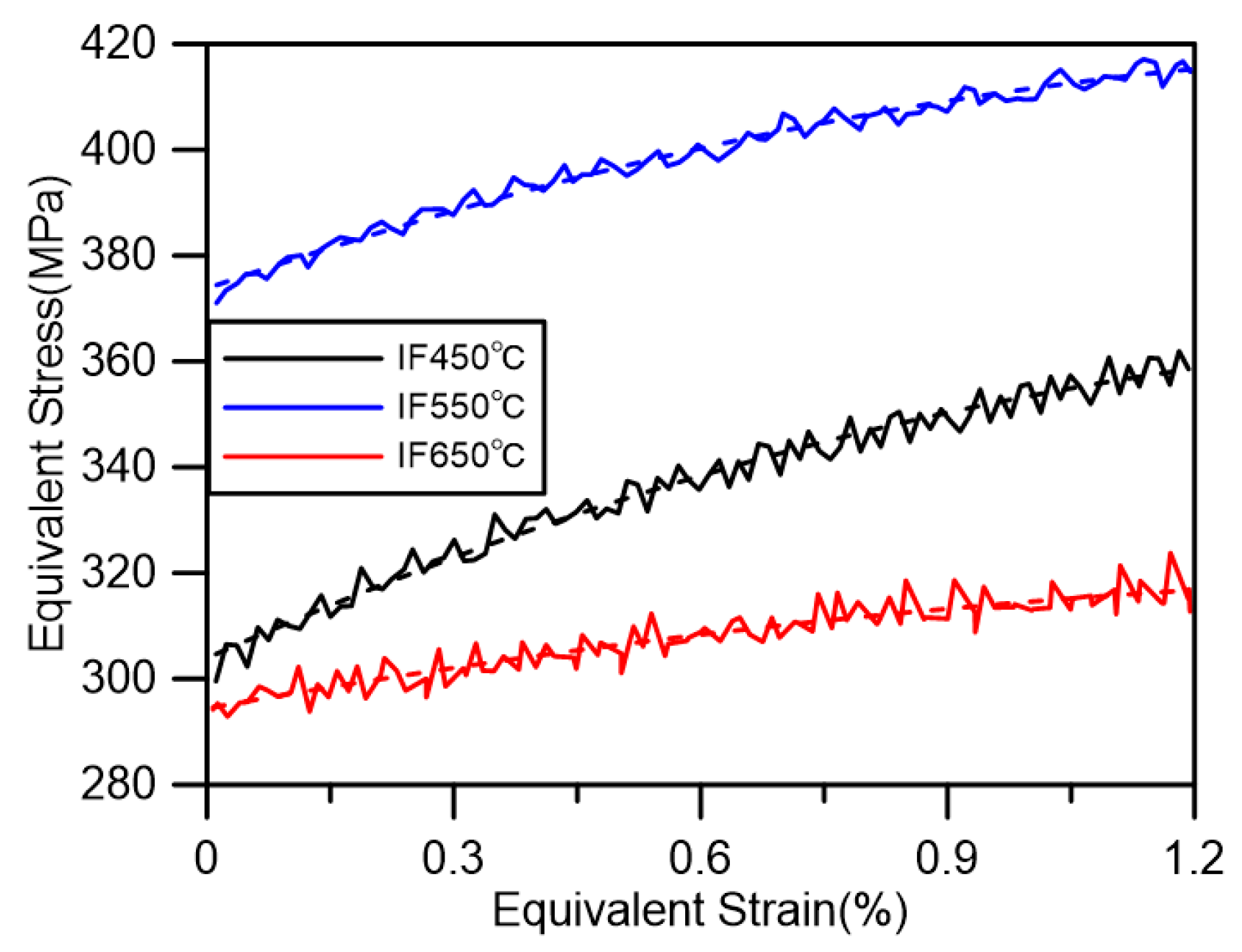
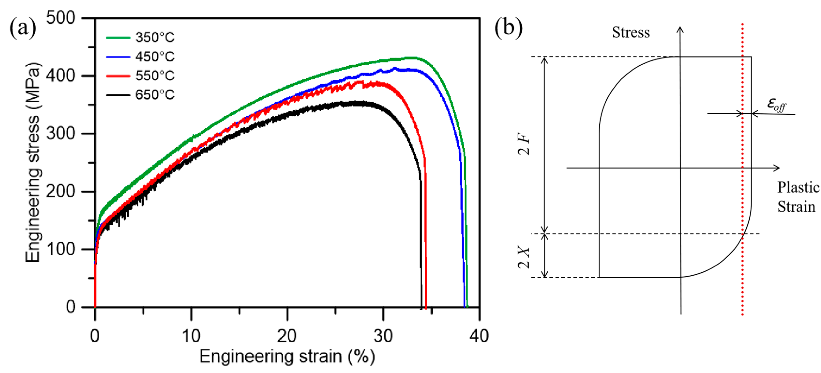
3.1. Cyclic Stress Response
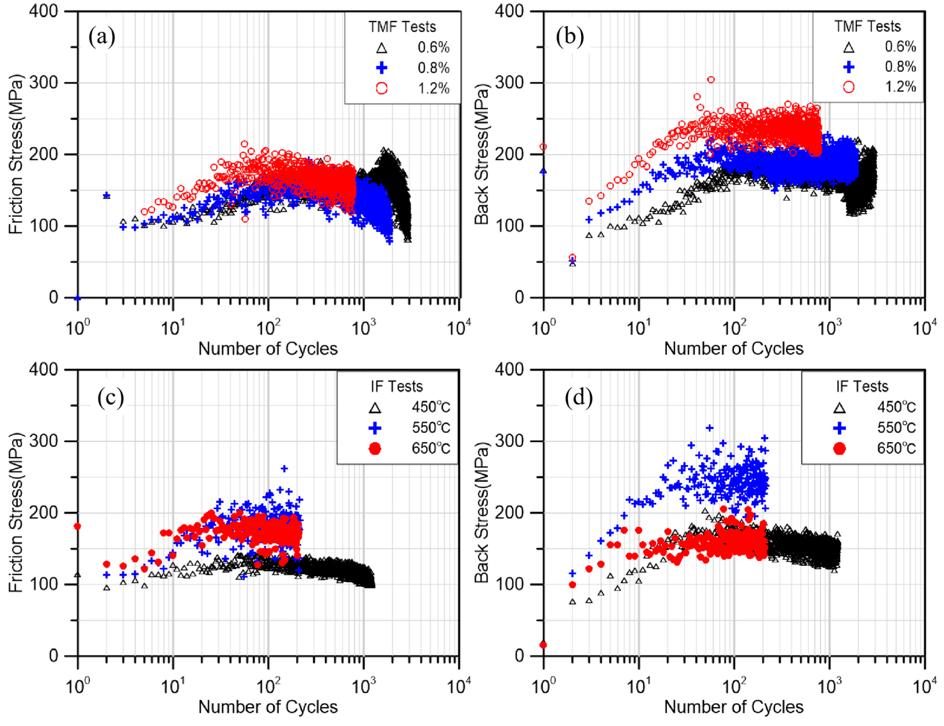
3.2. Friction Stress and Back Stress
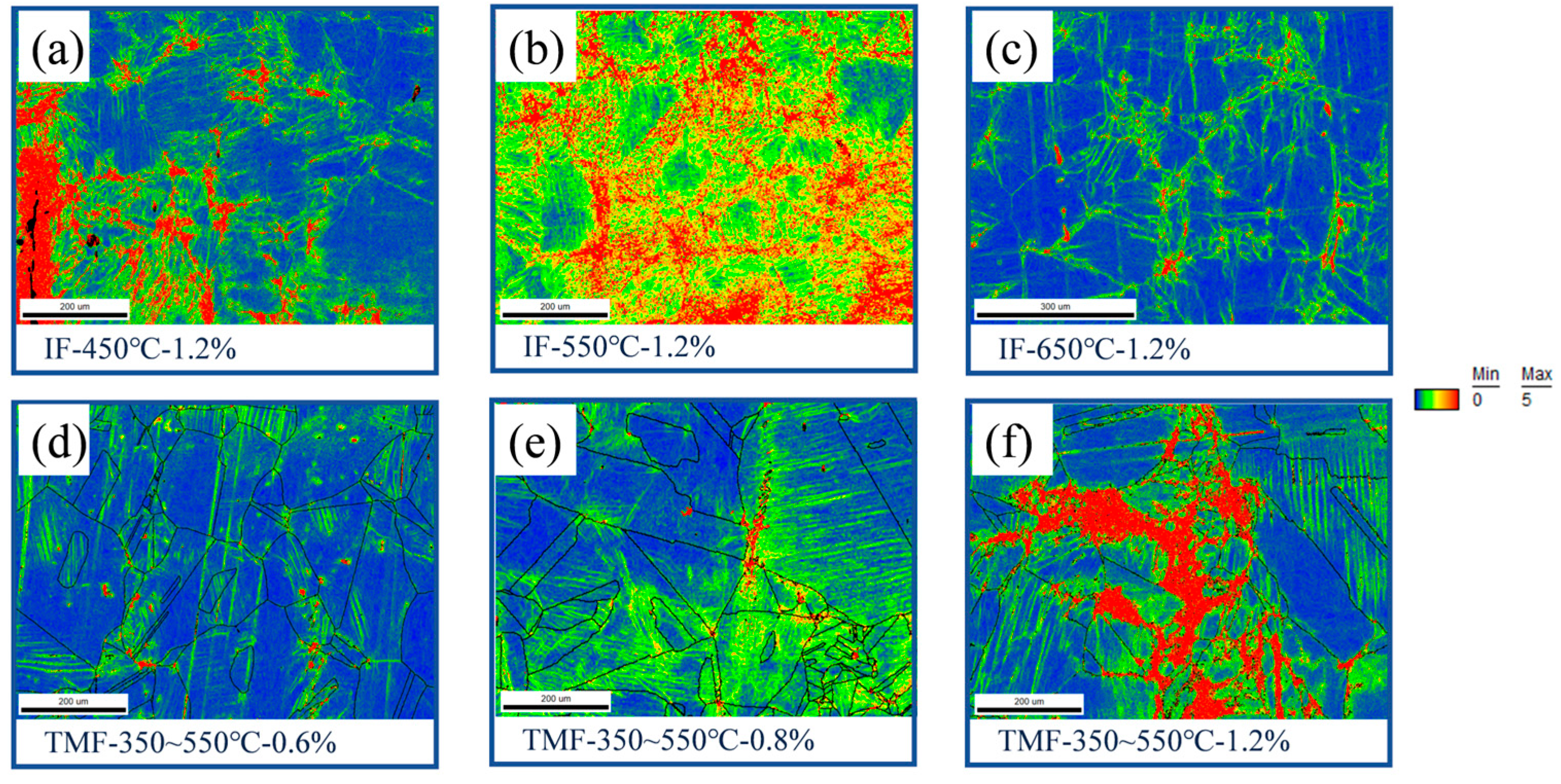
3.3. Microanalysis
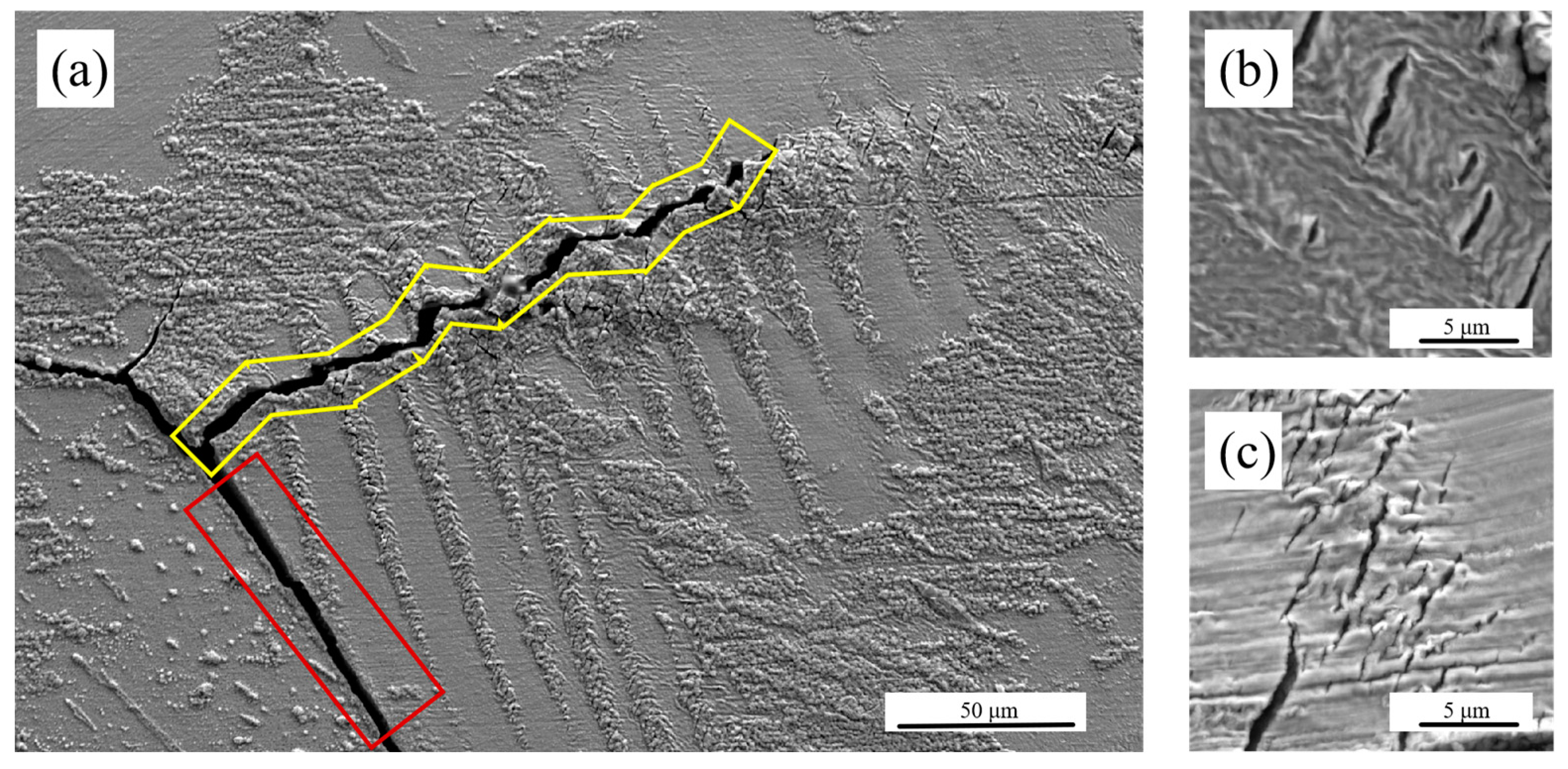
3.3.1. Surface Crack
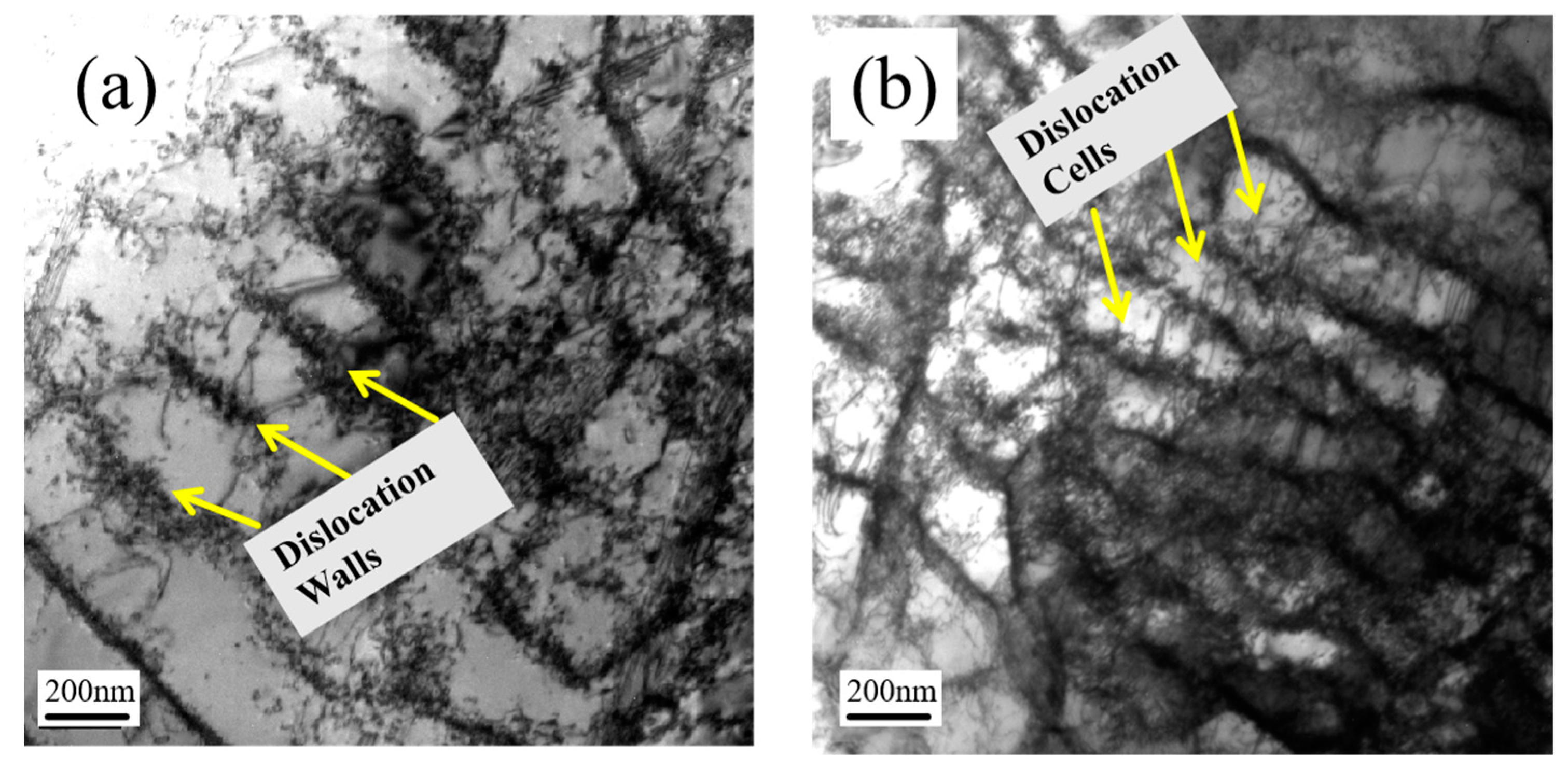
3.3.2. Dislocation Evolution
4. Conclusions
- Temperature significantly impacts DSA behavior in materials. Similar to axial loading tests, DSA behavior in 316LN material is most pronounced during torsional loading at 550 °C.
- Cracks formed in the oxide layer within slip bands on the specimen surface precede the main cracks and influence their propagation direction during the crack growth process.
- Under conditions of small deformation, secondary hardening occurs in the specimen due to the increased frictional stress caused by accumulated planar slip. However, this phenomenon diminishes as the strain amplitude increases.
- Under conditions of large plastic deformation, 316LN exhibits a mixed slip pattern at 550 °C, whereas cross-slip dominates at 650 °C. This results in lower back stress and frictional stress at 650 °C compared to 550 °C.
- The material exhibits a higher dislocation density during the 550 °C IF test due to frequent DSA. In contrast, the material has a lower dislocation density at 650 °C due to sufficient thermal recovery.
Author Contributions
Funding
Institutional Review Board Statement
Informed Consent Statement
Data Availability Statement
Conflicts of Interest
Abbreviations
| DSA | Dynamic strain aging |
| EBSD | Electron back scatter diffraction |
| EDS | Energy dispersive spectrometer |
| IF | Isothermal fatigue |
| KAM | Kernel average misorientation |
| KWL | Kuhlmann–Wilsorf–Laird |
| OPS | Oxide polishing suspension |
| PWR | Pressurized water reactor |
| SEM | Scanning electron microscope |
| TEM | Transmission electron microscope |
| TMF | Thermomechanical fatigue |
| WEDM | Wire electrical discharge machining |
References
- Pham, M.S.; Holdsworth, S.R. Dynamic Strain Ageing of AISI 316L during Cyclic Loading at 300 °C: Mechanism, Evolution, and Its Effects. Mater. Sci. Eng. A 2012, 556, 122–133. [Google Scholar] [CrossRef]
- Samuel, K.G.; Mannan, S.L.; Rodriguez, P. Serrated Yielding in AISI 316 Stainless Steel. Acta Metall. 1988, 36, 2323–2327. [Google Scholar] [CrossRef]
- Ray, S.K.; Samuel, K.G.; Rodriguez, P. Dynamic Strain Ageing in Type 316 Stainless Steel at 300 K. Scr. Metall. Mater. 1992, 27, 271–276. [Google Scholar] [CrossRef]
- Shanmugavel, M.; Nandagopal, M.; Sandhya, R.; Bhanu Sankara Rao, K.; Gnanamoorthy, R. Evaluation of Activation Energy for Dynamic Strain Aging Process in 316L(N)/316(N) SS Weld Joints. Trans. Indian Inst. Met. 2008, 61, 301–306. [Google Scholar] [CrossRef]
- Nagesha, A.; Valsan, M.; Kannan, R.; Bhanu Sankara Rao, K.; Bauer, V.; Christ, H.-J.; Singh, V. Thermomechanical Fatigue Evaluation and Life Prediction of 316L(N) Stainless Steel. Int. J. Fatigue 2009, 31, 636–643. [Google Scholar] [CrossRef]
- Prasad Reddy, G.V.; Nagesha, A.; Sandhya, R.; Sankaran, S.; Mathew, M.D.; Bhanu Sankara Rao, K. Thermomechanical and Isothermal Fatigue Behavior of 316LN Stainless Steel with Varying Nitrogen Content. Metall. Mater. Trans. A 2015, 46, 695–707. [Google Scholar] [CrossRef]
- Ma, Y.; Zhang, Z.; Zhang, X.; Yin, H.; Liang, B.; Tan, J.; Wu, X.; Han, E.-H.; Ke, W. Effects of Strain Rate on Low-Cycle Fatigue Crack Growth Behavior of 316LN Weld Metal in High-Temperature Pressurized Water. Corros. Sci. 2022, 199, 110169. [Google Scholar] [CrossRef]
- Kolmorgen, R.; Biermann, H. Thermo Mechanical Fatigue Behaviour of a Duplex Stainless Steel in the Range of 350–600 °C. Int. J. Fatigue 2014, 65, 2–8. [Google Scholar] [CrossRef]
- Yin, P.; Zhang, W.; Zhang, Y.; Yang, Q.; Liang, F.; Chang, L.; Zhou, C. Cyclic Deformation Mechanism and Fracture Behaviour of 316L Stainless Steel under Thermomechanical Fatigue Loading. J. Mater. Res. Technol. 2023, 24, 4484–4499. [Google Scholar] [CrossRef]
- Suresh Kumar, T.; Nagesha, A.; Mariappan, K.; Kumar Dash, M. Deformation and Failure Behaviour of 316 LN Austenitic Stainless Steel Weld Joint under Thermomechanical Low Cycle Fatigue in As-Welded and Thermally Aged Conditions. Int. J. Fatigue 2021, 149, 106269. [Google Scholar] [CrossRef]
- Li, B.; Zheng, Y.; Shi, S.; Chen, X. Microcrack Nucleation and Early Crack Growth of a Nuclear Grade Nitrogen Alloyed Austenitic Stainless Steel X2CrNiMo18.12 under Thermomechanical Fatigue Loading. Int. J. Press. Vessel. Pip. 2019, 172, 188–198. [Google Scholar] [CrossRef]
- Choudhary, B.K. Activation Energy for Serrated Flow in Type 316L(N) Austenitic Stainless Steel. Mater. Sci. Eng. A 2014, 603, 160–168. [Google Scholar] [CrossRef]
- Pham, M.S.; Holdsworth, S.R.; Janssens, K.G.F.; Mazza, E. Cyclic Deformation Response of AISI 316L at Room Temperature: Mechanical Behaviour, Microstructural Evolution, Physically-Based Evolutionary Constitutive Modelling. Int. J. Plast. 2013, 47, 143–164. [Google Scholar] [CrossRef]
- Nagesha, A.; Kannan, R.; Parameswaran, P.; Sandhya, R.; Rao, K.B.S.; Singh, V. A Comparative Study of Isothermal and Thermomechanical Fatigue on Type 316L(N) Austenitic Stainless Steel. Mater. Sci. Eng. A 2010, 527, 5969–5975. [Google Scholar] [CrossRef]
- Prasad Reddy, G.V.; Nagesha, A.; Kannan, R.; Sandhya, R.; Laha, K. Thermomechanical Fatigue Behavior of Nitrogen Enhanced 316LN Stainless Steel: Effect of Cyclic Strain. Int. J. Fatigue 2017, 103, 176–184. [Google Scholar] [CrossRef]
- Sarkar, A.; Nagesha, A.; Sandhya, R.; Laha, K. Manifestations of Dynamic Strain Aging under Low and High Cycle Fatigue in a Type 316LN Stainless Steel. Mater. High Temp. 2018, 35, 523–528. [Google Scholar] [CrossRef]
- Sarkar, A.; Nagesha, A.; Parameswaran, P.; Sandhya, R.; Okazaki, M. Implications of Dynamic Strain Aging under LCF-HCF Interactions in a Type 316LN Stainless Steel. Mater. Sci. Eng. A 2017, 708, 91–103. [Google Scholar] [CrossRef]
- Jia, X. A New Explanation for the Effect of Dynamic Strain Aging on Negative Strain Rate Sensitivity in Fe–30Mn–9Al–1C Steel. Materials 2019, 12, 3426. [Google Scholar] [CrossRef] [PubMed]
- Zheng, Y.; Li, B.; Zhao, J.; Liu, C.; Itoh, T.; Chen, X. Thermomechanical and Isothermal Fatigue Crack Propagation Testing Method for 316LN Austenitic Stainless Steel. Fatigue Fract. Eng. Mat. Struct. 2022, 45, 3040–3052. [Google Scholar] [CrossRef]
- Zheng, Y.; Li, B.; Yang, J.; Zhang, Z.; Chen, X. Insights into Thermomechanical Fatigue Behavior of Nitrogen Alloyed 316LN Stainless Steel under Various Temperature Cycling Ranges. J. Mater. Res. Technol. 2024, 29, 3990–4003. [Google Scholar] [CrossRef]
- Babinský, T.; Šulák, I.; Poczklán, L.; Guth, S. A Comparison of Conventional and Additively Manufactured 316L under Thermomechanical Fatigue. Int. J. Fatigue 2024, 187, 108477. [Google Scholar] [CrossRef]
- Li, B.; Zheng, Y.; Liu, C.; Li, Q.; Zhang, Z.; Chen, X. Torsional Thermomechanical Fatigue Behavior of 316LN Stainless Steel. Mater. Sci. Eng. A 2020, 789, 139676. [Google Scholar] [CrossRef]
- Lin, Q.; Chen, X.; Zheng, Y.; Zhang, Z.; Chen, G.; Li, B. Multiaxial Isothermal and Thermomechanical Fatigue Behavior of 316LN Stainless Steel. Int. J. Press. Vessel. Pip. 2022, 197, 104633. [Google Scholar] [CrossRef]
- Li, D.-H.; Shang, D.-G.; Zhang, C.-C.; Liu, X.-D.; Li, F.-D.; Li, Z.-G. Thermo-Mechanical Fatigue Damage Behavior for Ni-Based Superalloy under Axial-Torsional Loading. Mater. Sci. Eng. A 2018, 719, 61–71. [Google Scholar] [CrossRef]
- Sun, J.; Yuan, H. Cyclic Plasticity Modeling of Nickel-Based Superalloy Inconel 718 under Multi-Axial Thermo-Mechanical Fatigue Loading Conditions. Int. J. Fatigue 2019, 119, 89–101. [Google Scholar] [CrossRef]
- Sun, J.; Yuan, H. Life Assessment of Multiaxial Thermomechanical Fatigue of a Nickel-Based Superalloy Inconel 718. Int. J. Fatigue 2019, 120, 228–240. [Google Scholar] [CrossRef]
- Brookes, S.P.; Kühn, H.-J.; Skrotzki, B.; Klingelhöffer, H.; Sievert, R.; Pfetzing, J.; Peter, D.; Eggeler, G. Axial–Torsional Thermomechanical Fatigue of a near-γ TiAl-Alloy. Mater. Sci. Eng. A 2010, 527, 3829–3839. [Google Scholar] [CrossRef]
- Liu, Y.; Kang, G.; Gao, Q. A Multiaxial Stress-Based Fatigue Failure Model Considering Ratchetting–Fatigue Interaction. Int. J. Fatigue 2010, 32, 678–684. [Google Scholar] [CrossRef]
- Li, H.; Kang, G.; Liu, Y.; Jiang, H. Non-Proportionally Multiaxial Cyclic Deformation of AZ31 Magnesium Alloy: Experimental Observations. Mater. Sci. Eng. A 2016, 671, 70–81. [Google Scholar] [CrossRef]
- Dong, Y.; Kang, G.; Liu, Y.; Wang, H.; Cheng, X. Dislocation Evolution in 316L Stainless Steel during Multiaxial Ratchetting Deformation. Mater. Charact. 2012, 65, 62–72. [Google Scholar] [CrossRef]
- Itoh, T.; Yang, T. Material Dependence of Multiaxial Low Cycle Fatigue Lives under Non-Proportional Loading. Int. J. Fatigue 2011, 33, 1025–1031. [Google Scholar] [CrossRef]
- Wu, M.; Itoh, T.; Shimizu, Y.; Nakamura, H.; Takanashi, M. Low Cycle Fatigue Life of Ti–6Al–4V Alloy under Non-Proportional Loading. Int. J. Fatigue 2012, 44, 14–20. [Google Scholar] [CrossRef]
- Zheng, Y.; Chen, X.; Zhang, Z.; Shi, S.; Chen, G.; Li, B. Multiaxial Low Cycle Fatigue Behavior and Life Prediction Method of 316LN Stainless Steel at 550 °C. Int. J. Fatigue 2022, 156, 106637. [Google Scholar] [CrossRef]
- ASTM E2207-08; Practice for Strain-Controlled Axial-Torsional Fatigue Testing with Thin-Walled Tubular Specimens. ASTM International: West Conshohocken, PA, USA, 2010. [CrossRef]
- Zheng, Y.; Li, B.; Chen, X. Isothermal and Thermomechanical Fatigue Crack Growth Behavior of 316LN Stainless Steel under Load- and Strain-controlled Modes. Fatigue Fract. Eng. Mat. Struct. 2024, 47, 3061–3080. [Google Scholar] [CrossRef]
- Zheng, Y.; Li, B.; Li, Q.; Liu, C.; Chen, X. Ratcheting Deformation Behavior of 316LN Stainless Steel under Thermomechanical and Isothermal Loadings. Int. J. Fatigue 2020, 138, 105718. [Google Scholar] [CrossRef]
- McCormigk, P.G. A Model for the Portevin-Le Chatelier Effect in Substitutional Alloys. Acta Metall. 1972, 20, 351–354. [Google Scholar] [CrossRef]
- Gupta, C.; Chakravartty, J.K.; Wadekar, S.L.; Dubey, J.S. Effect of Serrated Flow on Deformation Behaviour of AISI 403 Stainless Steel. Mater. Sci. Eng. A 2000, 292, 49–55. [Google Scholar] [CrossRef]
- Hong, S.-G.; Lee, S.-B. Dynamic Strain Aging under Tensile and LCF Loading Conditions, and Their Comparison in Cold Worked 316L Stainless Steel. J. Nucl. Mater. 2004, 328, 232–242. [Google Scholar] [CrossRef]
- Mannan, S.L. Role of Dynamic Strain Ageing in Low Cycle Fatigue. Bull. Mater. Sci. 1993, 16, 561–582. [Google Scholar] [CrossRef]
- He, K.; Wang, Y.; Wang, H. Influence of Dynamic Strain Aging on Ferritic/Martensitic Steel and Stability Analysis. Fusion Eng. Des. 2021, 171, 112581. [Google Scholar] [CrossRef]
- Pham, M.S.; Solenthaler, C.; Janssens, K.G.F.; Holdsworth, S.R. Dislocation Structure Evolution and Its Effects on Cyclic Deformation Response of AISI 316L Stainless Steel. Mater. Sci. Eng. A 2011, 528, 3261–3269. [Google Scholar] [CrossRef]
- Wei, W.; Feng, Y.; Han, L.; Zhang, Q.; Zhang, J. Cyclic Hardening and Dynamic Strain Aging during Low-Cycle Fatigue of Cr-Mo Tempered Martensitic Steel at Elevated Temperatures. Mater. Sci. Eng. A 2018, 734, 20–26. [Google Scholar] [CrossRef]
- Yamanaka, K.; Mori, M.; Chiba, A. Nitrogen-Induced Dynamic Strain Aging in a Biomedical-Grade Co–Cr–Mo Alloy. Mater. Sci. Eng. A 2012, 552, 69–75. [Google Scholar] [CrossRef]
- Li, B.; Zheng, Y.; Zhao, J.; Shi, S.; Zhang, Z.; Chen, X. Cyclic Deformation Behavior and Dynamic Strain Aging of 316LN Stainless Steel under Low Cycle Fatigue Loadings at 550 °C. Mater. Sci. Eng. A 2021, 818, 141411. [Google Scholar] [CrossRef]
- De Almeida, L.H.; Le May, I.; Emygdio, P.R.O. Mechanistic Modeling of Dynamic Strain Aging in Austenitic Stainless Steels. Mater. Charact. 1998, 41, 137–150. [Google Scholar] [CrossRef]
- Hong, S.-G.; Lee, S.-B. Mechanism of Dynamic Strain Aging and Characterization of Its Effect on the Low-Cycle Fatigue Behavior in Type 316L Stainless Steel. J. Nucl. Mater. 2005, 340, 307–314. [Google Scholar] [CrossRef]
- Hong, S.; Lee, K.; Lee, S. Dynamic Strain Aging Effect on the Fatigue Resistance of Type 316L Stainless Steel. Int. J. Fatigue 2005, 27, 1420–1424. [Google Scholar] [CrossRef]
- Pham, M.; Holdsworth, S. Evolution of Relationships Between Dislocation Microstructures and Internal Stresses of AISI 316L During Cyclic Loading at 293 K and 573 K (20 °C and 300 °C). Metall. Mater. Trans. A 2014, 45, 738–751. [Google Scholar] [CrossRef]
- Kuhlmann-Wilsdorf, D.; Laird, C. Dislocation Behavior in Fatigue II. Friction Stress and Back Stress as Inferred from an Analysis of Hysteresis Loops. Mater. Sci. Eng. 1979, 37, 111–120. [Google Scholar] [CrossRef]
- Xu, H.; Ye, D.; Mei, L. A Study of the Back Stress and the Friction Stress Behaviors of Ti-6Al-4V Alloy during Low Cycle Fatigue at Room Temperature. Mater. Sci. Eng. A 2017, 700, 530–539. [Google Scholar] [CrossRef]
- Shao, C.; Shi, F.; Li, X. Cyclic Deformation Behavior of Fe-18Cr-18Mn-0.63N Nickel-Free High-Nitrogen Austenitic Stainless Steel. Metall. Mater. Trans. A 2015, 46, 1610–1620. [Google Scholar] [CrossRef]
- Wang, S.; Zhang, M.; Wu, H.; Yang, B. Study on the Dynamic Recrystallization Model and Mechanism of Nuclear Grade 316LN Austenitic Stainless Steel. Mater. Charact. 2016, 118, 92–101. [Google Scholar] [CrossRef]
- Fournier, B.; Sauzay, M.; Caës, C.; Noblecourt, M.; Mottot, M. Analysis of the Hysteresis Loops of a Martensitic Steel. Mater. Sci. Eng. A 2006, 437, 183–196. [Google Scholar] [CrossRef]
- Zhang, Y.; Yang, C.; Zhou, D.; Zhe, Y.; Meng, L.; Zhu, X.; Zhang, D. Effect of Stacking Fault Energy on Microstructural Feature and Back Stress Hardening in Cu-Al Alloys Subjected to Surface Mechanical Attrition Treatment. Mater. Sci. Eng. A 2019, 740–741, 235–242. [Google Scholar] [CrossRef]
- Zhi, H.; Antonov, S.; Zhang, C.; Guo, Z.; Su, Y. Origins of Back Stress Strengthening in Fe-22Mn-0.6C (-3Al) TWIP Steels. Mater. Sci. Eng. A 2020, 792, 139834. [Google Scholar] [CrossRef]
- Nagesha, A.; Kannan, R.; Srinivasan, V.S.; Sandhya, R.; Choudhary, B.K.; Laha, K. Dynamic Strain Aging and Oxidation Effects on the Thermomechanical Fatigue Deformation of Reduced Activation Ferritic-Martensitic Steel. Met. Mater. Trans. A 2016, 47, 1110–1127. [Google Scholar] [CrossRef]
- Li, B.; Zheng, Y.; Shi, S.; Zhang, Z.; Chen, X. Cyclic Deformation and Cracking Behavior of 316LN Stainless Steel under Thermomechanical and Isothermal Fatigue Loadings. Mater. Sci. Eng. A 2020, 773, 138866. [Google Scholar] [CrossRef]
- Lu, K.; Chauhan, A.; Litvinov, D.; Walter, M.; Tirunilai, A.S.; Freudenberger, J.; Kauffmann, A.; Heilmaier, M.; Aktaa, J. High-Temperature Low Cycle Fatigue Behavior of an Equiatomic CoCrFeMnNi High-Entropy Alloy. Mater. Sci. Eng. A 2020, 791, 139781. [Google Scholar] [CrossRef]
- Huang, K.; Logé, R.E. A Review of Dynamic Recrystallization Phenomena in Metallic Materials. Mater. Des. 2016, 111, 548–574. [Google Scholar] [CrossRef]


| C | Si | N | P | Mn | Cr | Ni | Co | Mo | Cu | Nb | Fe |
|---|---|---|---|---|---|---|---|---|---|---|---|
| 0.018 | 0.22 | 0.112 | 0.023 | 1.42 | 17.20 | 12.95 | 0.018 | 2.19 | 0.033 | 0.068 | Bal. |
Disclaimer/Publisher’s Note: The statements, opinions and data contained in all publications are solely those of the individual author(s) and contributor(s) and not of MDPI and/or the editor(s). MDPI and/or the editor(s) disclaim responsibility for any injury to people or property resulting from any ideas, methods, instructions or products referred to in the content. |
© 2025 by the authors. Licensee MDPI, Basel, Switzerland. This article is an open access article distributed under the terms and conditions of the Creative Commons Attribution (CC BY) license (https://creativecommons.org/licenses/by/4.0/).
Share and Cite
Zheng, Y.; Wang, F.; Xu, C. Isothermal and Thermomechanical Fatigue Behavior of 316LN Stainless Steel Under Torsional Loading. Materials 2025, 18, 541. https://doi.org/10.3390/ma18030541
Zheng Y, Wang F, Xu C. Isothermal and Thermomechanical Fatigue Behavior of 316LN Stainless Steel Under Torsional Loading. Materials. 2025; 18(3):541. https://doi.org/10.3390/ma18030541
Chicago/Turabian StyleZheng, Yiming, Fang Wang, and Caijun Xu. 2025. "Isothermal and Thermomechanical Fatigue Behavior of 316LN Stainless Steel Under Torsional Loading" Materials 18, no. 3: 541. https://doi.org/10.3390/ma18030541
APA StyleZheng, Y., Wang, F., & Xu, C. (2025). Isothermal and Thermomechanical Fatigue Behavior of 316LN Stainless Steel Under Torsional Loading. Materials, 18(3), 541. https://doi.org/10.3390/ma18030541