1. Introduction
The increasing global demand for aluminium, driven by its widespread use in automotive, aerospace, and construction industries, has heightened the need for sustainable production practices. Transitioning to a circular economy, where secondary (recycled) aluminium alloys replace primary production, offers significant environmental and economic benefits, including energy savings and reduced greenhouse gas emissions [
1,
2,
3,
4,
5].
However, aluminium recycling presents metallurgical challenges due to the presence of impurities such as iron, which are difficult to eliminate. Elevated iron content promotes the formation of hard and brittle intermetallic phases, notably β-Al
5FeSi, which degrade mechanical performance by acting as stress concentrators and fatigue crack initiation sites [
6,
7,
8,
9,
10,
11,
12]. These phases are often associated with increased porosity during solidification, further impairing the fatigue properties of cast components [
12,
13,
14,
15].
To address this, the use of self-hardening Al-Zn-Si-Mg alloys has gained attention. These alloys develop desirable mechanical properties through natural ageing at room temperature, eliminating the need for conventional T6 heat treatment [
16,
17,
18,
19]. This makes them particularly attractive for high-throughput, energy-efficient manufacturing. While self-hardening behaviour results in fine, densely distributed precipitates that enhance strength [
20,
21,
22], their fatigue resistance remains sensitive to microstructural heterogeneities such as Fe-rich intermetallics and casting defects.
Surface treatment methods, such as shot peening, offer a promising solution for improving fatigue life by inducing compressive residual stresses, closing surface-connected porosity, and increasing resistance to crack initiation [
23,
24,
25,
26,
27]. This method has demonstrated efficacy in various aluminium alloys by enhancing near-surface properties and delaying fatigue crack nucleation, especially in components with surface-adjacent defects.
Despite these advantages, the combined influence of iron content, intermetallic morphology, and shot peening coverage levels on fatigue resistance in secondary AlZn10Si8Mg alloys is not well established. A deeper understanding of these relationships is essential for advancing the use of recycled aluminium alloys in structural components subject to cyclic loading.
This study investigates the effects of shot peening on the fatigue life of secondary AlZn10Si8Mg alloys with two distinct iron contents (0.14 wt.% and 0.56 wt.%). Surface porosity, microstructure, and residual stress profiles are examined for their contribution to fatigue behaviour. By analysing the microstructure, mechanical properties, and fracture mechanisms, this work provides insights into how shot peening can enable broader application of secondary aluminium alloys in demanding engineering environments.
2. Experimental Procedures
2.1. Material and Specimen Preparation
Cylindrical test bars with a diameter of 20 mm and a length of 300 mm were produced from self-hardening secondary aluminium alloy AlZn10Si8Mg using a sand-casting process without any modification or refinement. Two variants with different iron contents were created: secondary Alloy A with 0.14 wt.% Fe and secondary Alloy B with 0.56 wt.% Fe. Stringent process control measures were employed to minimise contamination risk during melting, including carefully monitoring temperature, flux addition, and alloy addition. The chemical composition of the experimental alloys was determined using Optical Emission Spectroscopy (OES), and the results are presented in
Table 1. The EN-AC-71100 standard [
28] specifies a maximum iron content in these alloys of up to 0.3%. However, since iron is tough to remove during recycling [
9], this paper aims to verify whether alloys with a higher iron content can be used.
2.2. Shot Peening and Surface Roughness Measurement
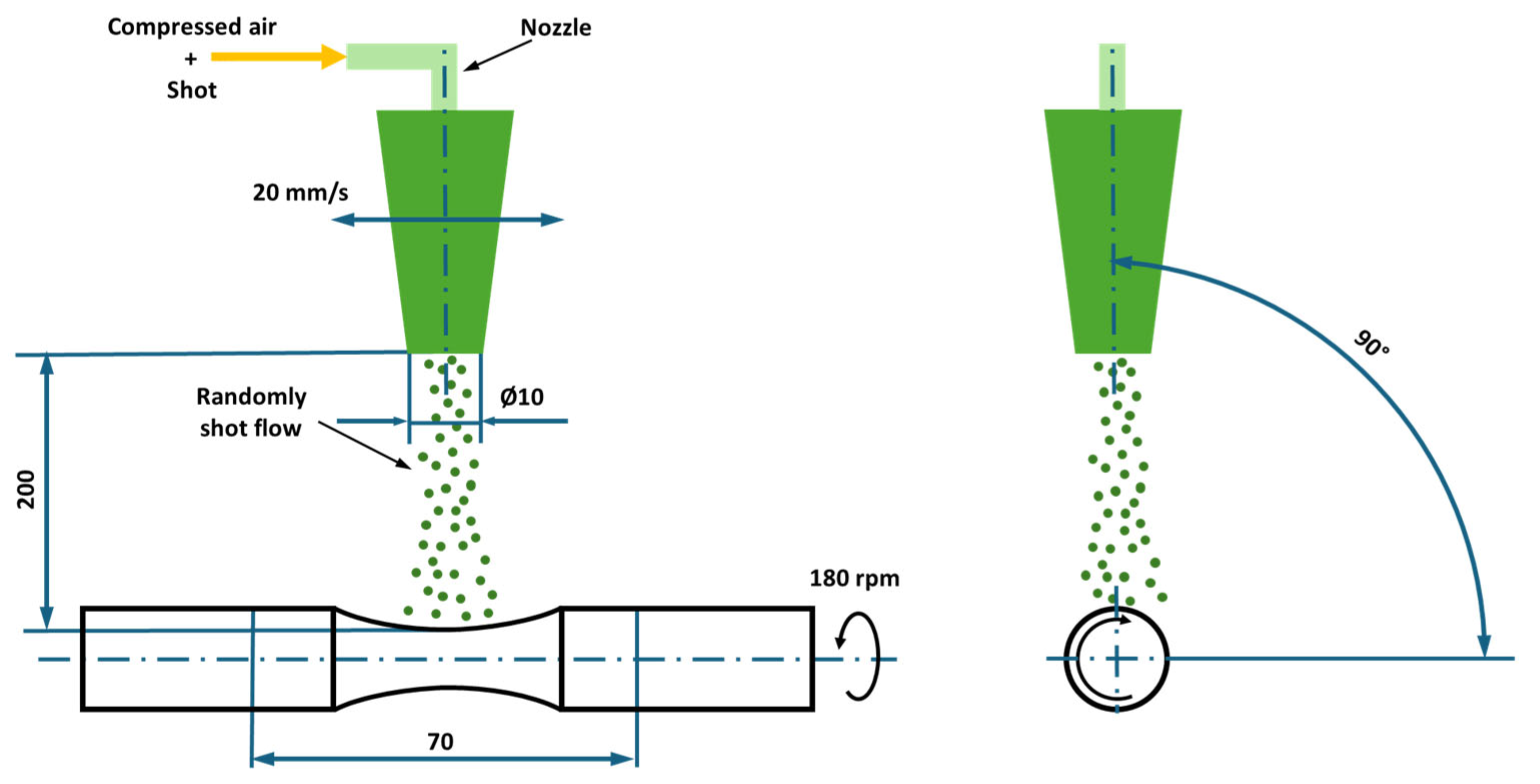
To determine the impact of shot peening on the fatigue limit, 15 test bars of Alloy A and 15 of Alloy B were subjected to shot peening with 100% coverage, termed SP100. For further comparison, an additional 15 test bars of Alloy A and 15 of Alloy B were shot peened with 1000% coverage, termed SP1000 (
Figure 1). Coverage refers to the percentage of the surface area impacted during the shot peening process. Coverage beyond 100% is achieved by prolonging the peening duration. To ensure reproducibility and comparability of the measurements, test bars were shot peened according to parameters specified in
Table 2.
Surface roughness was evaluated using an Alicona G5 Infinite Focus optical 3D measurement microscope (Alicona Imaging GmbH, Graz, Austria) following the ISO 4287 standard [
30]. Average values of standard roughness parameters, such as the arithmetic mean of the absolute ordinates (R
a), as well as the average values of the absolute heights of the five highest-profile peaks and the depths of the five deepest valleys within the evaluation length (R
z) from the reference line of the roughness profile, were reported for each experimental alloy.
2.3. Tensile Strength Test
Tensile testing was conducted on secondary aluminium Alloys A and B, represented by three specimens. Test bars were machined into specimen dimensions (
Figure 2) according to the ISO 6892-1 standard [
31]. Test bars were tested on an MTS Alliance RT/100 device at a strain rate of 0.7 mm/min, up to 2% strain, followed by a constant rate of 2 mm/min.
2.4. Microstructural Characterisation
Specimens for microstructural analysis were prepared from test bars according to ASTM E3 metallographic testing standards [
32] used for aluminium alloys. The microstructure was revealed on polished cross-sections etched with 0.5% HF (CentralChem, Bratislava, Slovakia). The microstructure was analysed using an optical microscope, NEOPHOT 32 (Carl Zeiss Jena GmbH, Jena, Germany), with NIS Elements software, version 4.20 (Nikon Corporation, Tokyo, Japan), covering quantitative measurements of casting defects. Thermo-Calc software (Thermo-Calc Software AB, Stockholm, Sweden) and the COST2 database (Thermo-Calc Software AB, Stockholm, Sweden) were used to conduct thermodynamic calculations to investigate the phase evolution. The phase equilibria of the system were calculated within the temperature range of 0–600 °C. The calculation considered elements P, N, Cu, Mg, Mn, Zn, Si, and Fe and the presence of different phases, including liquid, β-AlFeSi (monoclinic), eutectic Si (cubic diamond-A4), Laves phase MgZn
2 (hexagonal), α-Al (matrix FCC-A1), Mg
2Si (cubic), α-AlMnSi (cubic), Mg
2Zn
11 (cubic), Zn (hexagonal), θ-Al
2Cu (tetragonal), Al
6Mn (orthorhombic), and α-AlFeSi (cubic). Porosity was examined with a CT scanner ZEISS METROTOM (Carl Zeiss Industrielle Messtechnik GmbH, Oberkochen, Germany), and microfractographic examination was done using SEM TESCAN VEGA LMU II (TESCAN ORSAY HOLDING, a.s., Brno, Czech Republic).
2.5. Hardness and Microhardness Measurements
Brinell hardness testing followed the ISO 6506-1 standard [
33] using a NEXUS 3000 device (Innovatest Europe BV, Maastricht, The Netherlands). Hardness measurements were performed on polished cross-sections of the experimental samples, applying a load of 250 kgf with a dwell time of 15 s for each indentation. Five measurements were taken for each sample (Alloys A and B). Additionally, microhardness measurements were carried out following the EN ISO 6507-1 standard [
34], using a ZwickRoell hardness tester (ZwickRoell GmbH & Co. KG, Ulm, Germany). Ten measurements were taken for the eutectic and
α-matrix (HV 0.025) in Alloys A and B.
2.6. Fatigue Tests and Fractography Analysis
The effect of iron content on fatigue lifetime was studied by subjecting Alloys A and B to shot peening at different coverage levels (100% and 1000%), building on [
15] investigation of un-peened alloys. Fatigue testing followed the ISO 12107 standard [
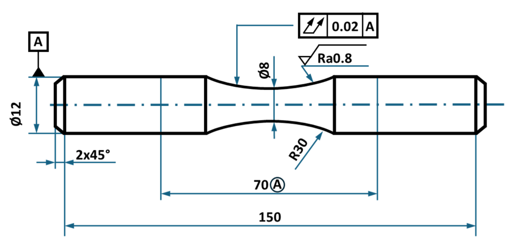
35], employing rotation-bending at a 30 Hz frequency and load ratio R = −1. Each alloy group, comprising 15 specimens, was tested at room temperature. Test bars were machined into an hourglass shape (
Figure 3) with a fillet radius sufficient to prevent notch-related fatigue phenomena. Fractographic analysis was performed on the fractured surfaces of the test bars using a Zeiss EVO50 scanning electron microscope (Carl Zeiss AG, Oberkochen, Germany).
2.7. Residual Stress Measurement
To evaluate the contribution of surface residual stresses to fatigue life, X-ray diffraction (XRD) was used to measure the stress distribution in shot peened specimens. The underlying hypothesis is that compressive residual stresses induced by shot peening delay fatigue crack initiation by suppressing tensile stress concentrations at surface-connected defects, thereby extending fatigue life. Conversely, if residual stress relaxation or shallow compressive zones occur, their contribution to fatigue resistance may be limited.
Residual stresses were assessed using an AST X-Stress 3000 portable X-ray diffractometer (Stresstech Oy, Jyväskylä, Finland) with CrKα radiation (λKα1 = 2.2898 Å), applying the sin2(ψ) method and targeting the 311 diffraction peak at a 2θ angle of 139°. The measurement protocol involved scanning seven tilt angles from −45° to +45° across three rotation directions (0°, 45°, and 90°) with a constant step size of 0.028°. Prior to data acquisition, system calibration was validated using a standard polycrystalline Al reference sample.
To obtain depth profiles of residual stress, successive surface layers (2 × 2 mm) were incrementally removed by electro-polishing. A solution of 94% CH3COOH and 6% HClO4 (CentralChem, Bratislava, Slovakia) was used at 35 V, enabling non-destructive layer removal with minimal alteration of the underlying stress state. The evolution of stress with depth was used to estimate the effective penetration of compressive stress and to relate these findings to crack initiation zones observed in fractographic analysis.
3. Results
3.1. Tensile Testing and Hardness
Tensile tests revealed similar mechanical properties between the two secondary AlZn10Si8Mg alloys despite their differing iron contents (
Table 3). Alloy A (0.14 wt.% Fe) and Alloy B (0.56 wt.% Fe) both exhibited ultimate tensile strengths around 180 MPa and elongations to failure of 2%. Hardness values (HB and HV) also remained largely unchanged between the alloys, although a notable microhardness contrast was observed between the α-Al matrix and eutectic Si. The latter phase demonstrated ~50 HV higher hardness due to its covalent bonding and diamond cubic structure. These findings are consistent with prior studies showing that local hardness variations in eutectic networks can act as microstructural barriers to dislocation movement [
18,
22]. However, their role in fatigue is not only governed by hardness but also by spatial distribution and morphology.
3.2. Microstructure Analysis
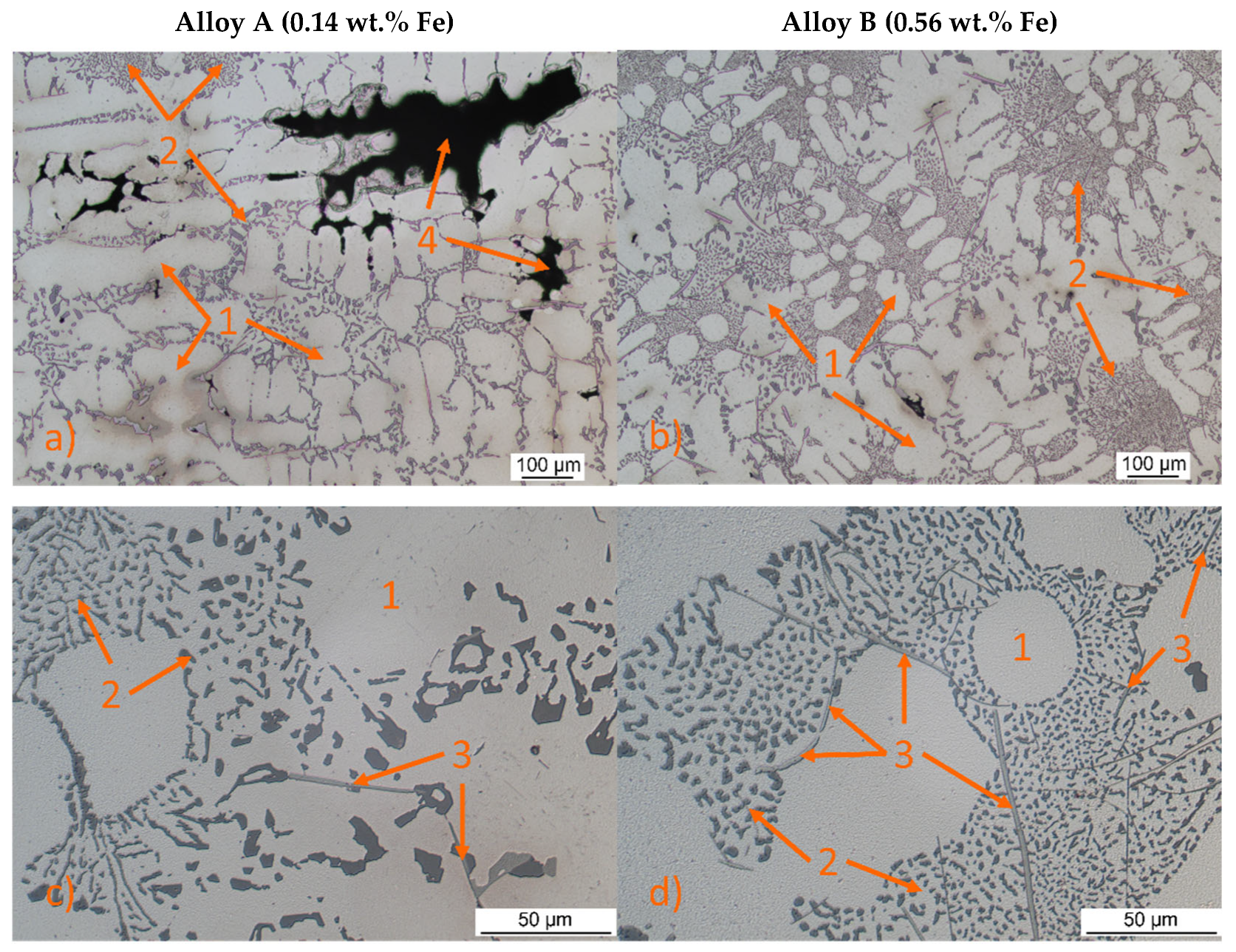
Both secondary aluminium alloys A and B, as shown in
Figure 4, exhibited similar microstructures consisting of α-phase (
Figure 4—no. 1), eutectic Si crystals (
Figure 4—no. 2), and various intermetallic phases, including Mg
2Si, β-Al
5FeSi needles (
Figure 4—no. 3), and ternary eutectic Al-MgZn
2-Cu) phases. The Al-MgZn
2-Cu and Mg
2Si phases were only visible in minor proportions and did not significantly impact the overall properties. The α-phase, a substitutional solid solution of Zn in Al, appeared in the form of dendrites. Eutectic silicon particles were observed as small, poorly rounded grains located mainly at the periphery of α-phase dendrites. Eutectic silicon crystals appear to be finer in the centre of the eutectic. At the eutectic/matrix interface they are more angular and larger, which can lead to stress localization.
The Fe phases manifested as β-Al
5FeSi needles, with Alloy A (0.14 wt.% Fe) showing slightly coarser eutectic silicon and shorter, thinner β-Al
5FeSi phases compared to Alloy B (0.56 wt.% Fe). Previous work has shown that β-Al
5FeSi, due to its brittle and elongated morphology, significantly contributes to fatigue crack initiation [
10,
11,
36,
37]. These phases are often located near eutectic regions, and when aligned with eutectic silicon and pores, can form connected networks that facilitate early-stage crack propagation. Thus, the combined effect of pore morphology, Fe-rich intermetallics, and eutectic Si distribution needs to be considered for an accurate fatigue assessment. The microstructure also revealed shrinkage porosity (
Figure 4—no. 4) in regions where solidification was last to occur, such as thick sections, junctions, and regions farthest from the cooling source. These areas are prone to shrinkage defects due to insufficient feeding of molten metal during solidification, resulting in voids or pores [
38].
Equilibrium phase diagrams (
Figure 5) were constructed to illustrate the phase evolution with temperature for Alloy A, revealing typical phases including
α-Al (matrix), eutectic Si, Al
5FeSi, Mg
2Si, and AlMgZn
2Cu. Aluminium nucleation was observed at 580 °C, followed by silicon nucleation at 570 °C. Solidification and phase growth simulations elucidated a sequential formation of phases: (Al) +
β-Al
5FeSi
→ (Al) +
β-Al
5FeSi + Mg
2Si
→ (Al) +
β-Al
5FeSi + Mg
2Si + AlMgZn
2Cu. The β-Al
5FeSi phase solidified first at 550 °C followed by Mg
2Si at 500 °C and AlMgZn
2Cu at 200 °C.
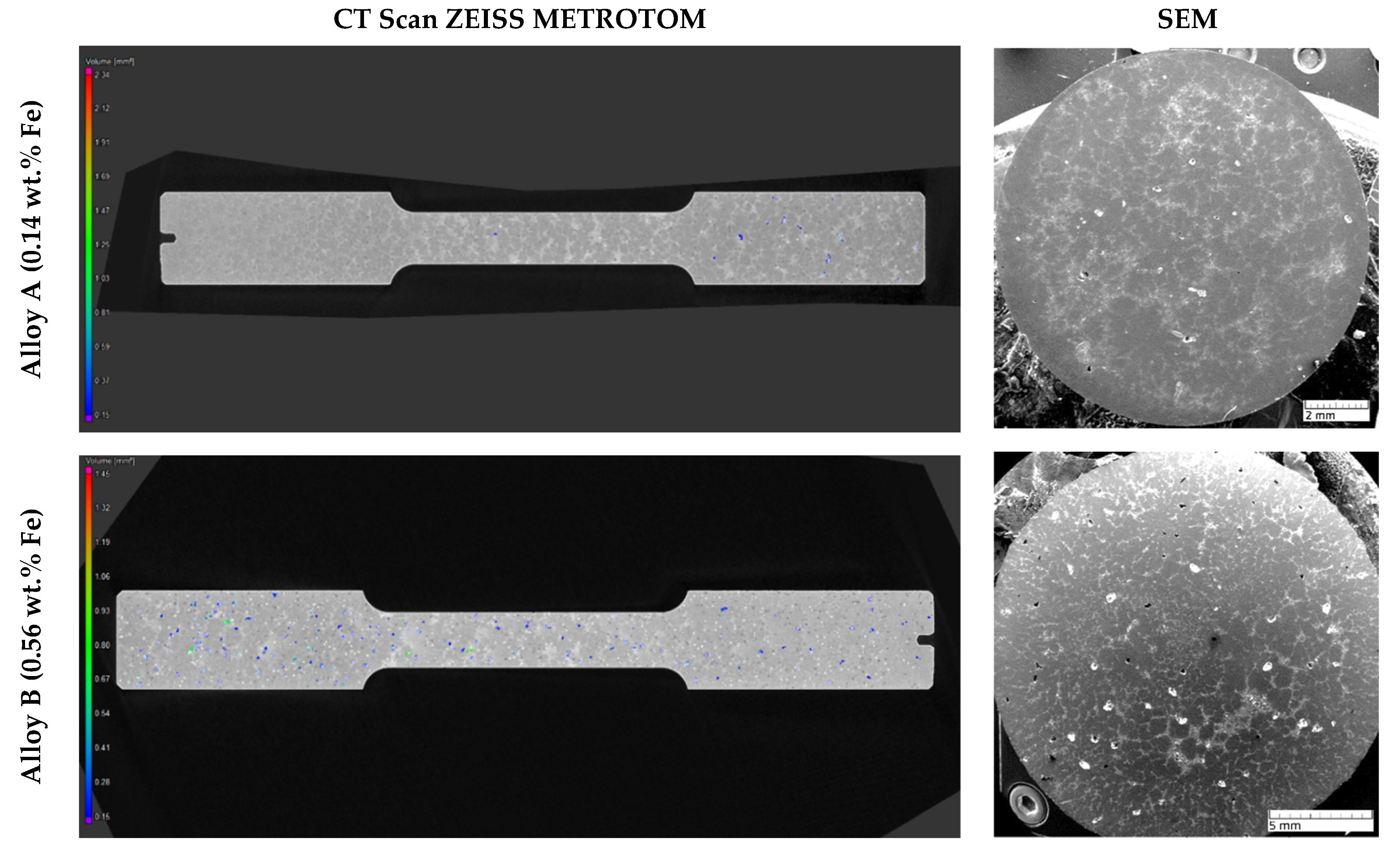
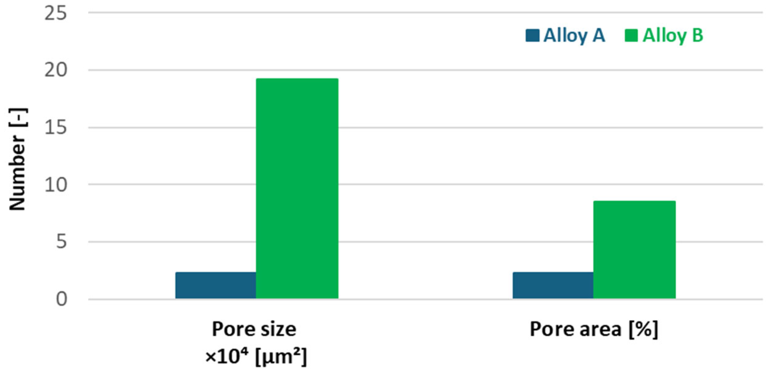
Increasing iron content in the experimental alloys significantly enhances porosity. Alloy B exhibited larger, more widely distributed pores than Alloy A, increasing total pore area from 2.26% to 8.5% (
Figure 6;
Figure 7). Porosity, particularly when irregular in shape or located near hard phases, amplifies stress concentrations. As shown in prior work [
38], such shrinkage porosity acts as a dominant fatigue crack nucleation site in cast aluminium alloys.
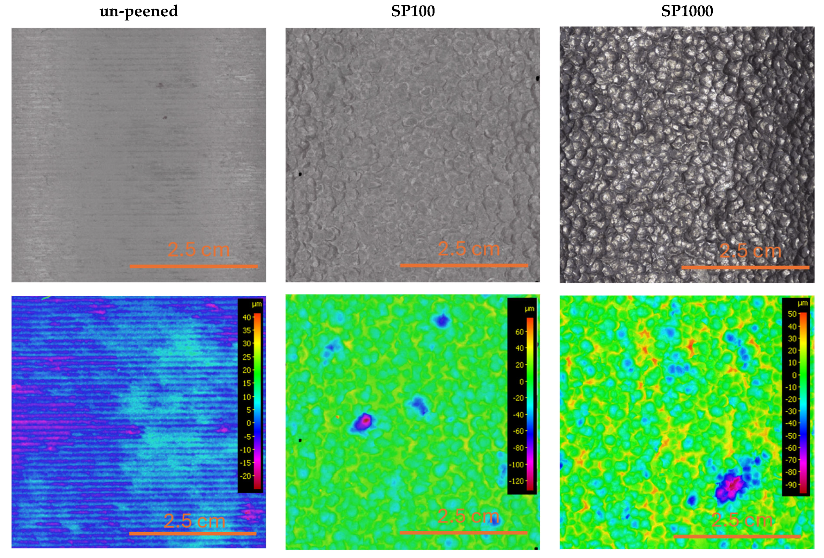
Figure 8 shows the top surface microstructures of Alloy A in the un-peened (machined) condition and after shot peening at 100% and 1000% coverage. Despite identical chemical composition across all samples, notable differences in surface morphology emerged due to mechanical treatment. Shot peening introduced substantial plastic deformation, visibly altering the surface and partially closing existing pores. This localized densification likely contributed to reduced stress concentrations at defect sites. Corresponding surface roughness profiles (
Figure 9) confirmed a progressive increase in roughness with higher peening coverage. The un-peened sample exhibited an R
a of 1.8 μm (R
z = 9.9 μm), which increased to 5.78 μm (R
z = 33.7 μm) at 100% and to 8.57 μm (R
z = 47.6 μm) at 1000% coverage. Although increased surface roughness is typically associated with earlier crack initiation, the observed improvement in fatigue life suggests that the beneficial effects of pore compression and induced compressive residual stress outweigh the potential drawbacks of surface topography.
3.3. High-Cycle Fatigue Strength and Residual Stress Analysis
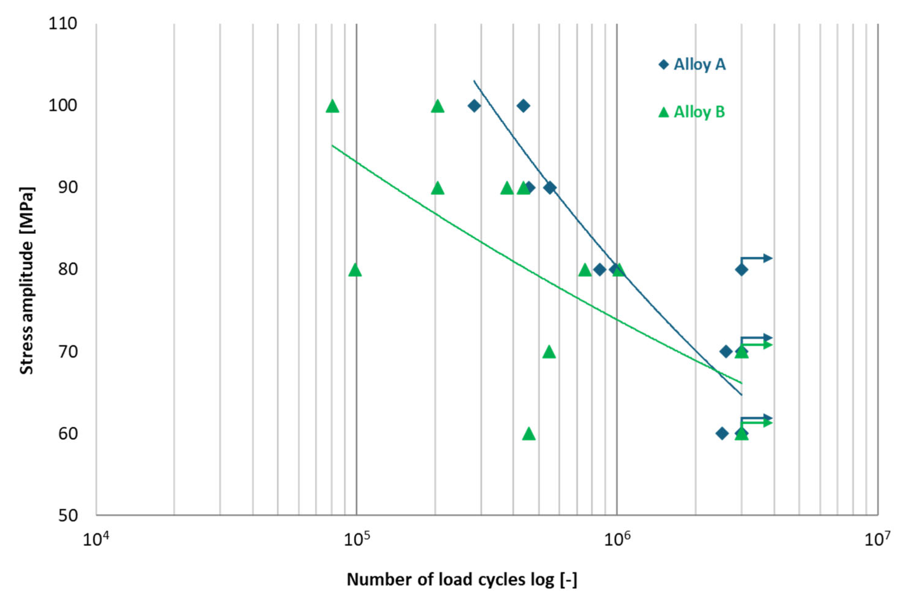
The high-cycle fatigue strength results for Alloys A and B were previously published in [
15] research, with the test results illustrated in
Figure 10. An S-N curve was constructed, indicating the fatigue limit for Alloy A at
= 65 MPa and for Alloy B at
= 66 MPa. Markers with arrows indicate specimens that did not fail before reaching the cycle limit (run-out). Despite a higher percentage of Fe, the results indicated that specimens exhibited extended fatigue life, despite elevated iron content. Building on this research, samples of Alloys A and B were shot peened at different coverage levels and underwent high-cycle fatigue testing under the same conditions as in the [
15] study.
Fatigue testing confirmed the detrimental effect of increased Fe content on fatigue resistance. However, shot peening improved the fatigue limit of both alloys. Alloy A showed a fatigue limit increase from
= 65 MPa (un-peened) to 79 MPa (SP100) and 78 MPa (SP1000), while Alloy B improved from 66 MPa to 70 MPa under SP1000 treatment (
Figure 11). The more modest improvement in Alloy B is likely due to its higher initial defect density and the presence of more pronounced intermetallics. To provide a clearer comparison of the fatigue performance,
Table 4 summarizes the experimentally determined fatigue limits of the two studied alloys under different surface conditions.
Given the interplay between residual stress and fatigue behaviour, the distribution of residual stress in the experimental alloys was measured.
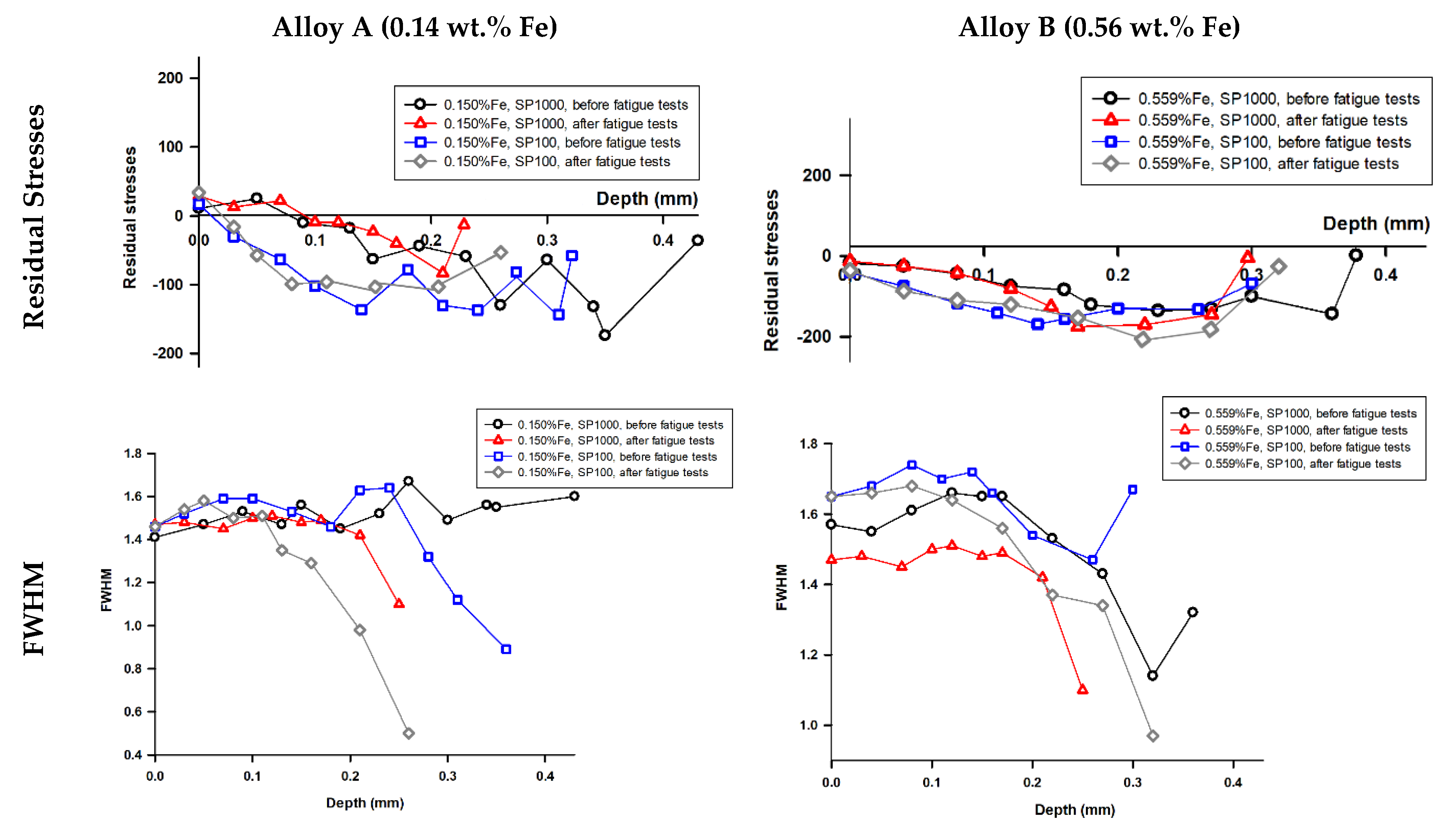
Figure 12 presents residual stress assessment results in secondary aluminium Alloys A and B after shot peening for both SP100 and SP1000 treatments. The beneficial effects of shot peening are primarily attributed to compressive residual stresses and pore closure. Compressive surface stresses are known to suppress microcrack nucleation, and this effect was confirmed here. However, their effectiveness is limited by penetration depth (~0.4 mm), as also shown in residual stress profiles (
Figure 12). These residual stresses do not significantly influence fatigue crack initiation in regions beyond this depth, where pores and Fe phases are more crucial. Increasing the peening coverage level from 100% to 1000% did not enhance the residual stress field; the stored energy, represented by the area under the Full Width at Half Maximum (FWHM) versus depth curves, remained nearly identical. The FWHM decreased with depth, indicating diminished work hardening and residual stress effects beyond 0.4 mm below the original surface. This suggests that the shot peening process had no significant impact beyond this depth.
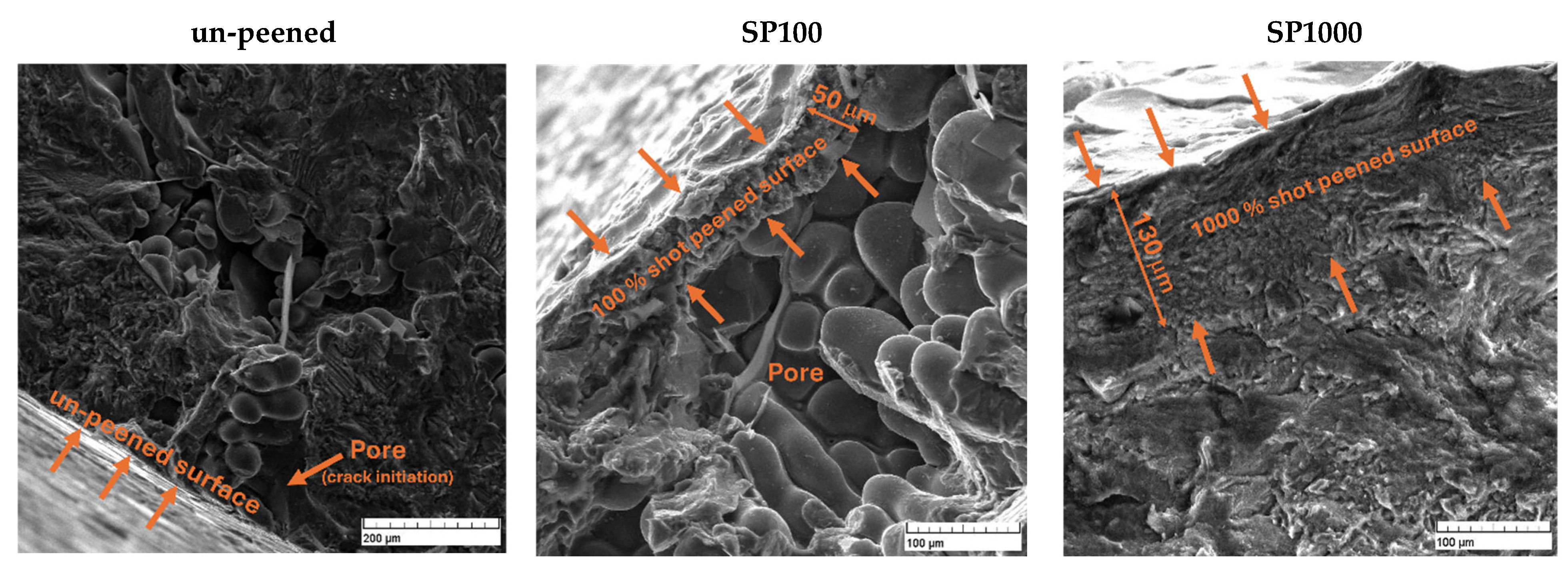
Fatigue cracks in un-peened Alloys A and B samples were primarily initiated from casting defects, such as pores or shrinkage cavities, as illustrated in
Figure 13. These defects are typically located near or at the specimen’s free surface. The shot peening process effectively mitigated these issues by visibly reducing surface porosity, minimizing pore size, and decreasing their overall number. Surface pores were visually reduced by shot peening, as seen in
Figure 13, supporting the conclusion that mechanical densification helps to eliminate critical crack initiation sites. While surface roughness increased post-peening, its negative impact was outweighed by the benefits of residual stress and porosity reduction, in agreement with observations from [
27] on fretting fatigue. This improvement positively impacted the fatigue lifetime of the materials. The thickness of the shot peened layer varied with different levels of shot peening coverage. For SP100, the layer thickness averaged approximately 50 μm, whereas, for SP1000, it increased to about 130 μm. Despite these variations, fatigue cracks still initiated from the surface, albeit at significantly fewer locations due to the treatment.
In summary, the fatigue lifetime of recycled AlZn10Si8Mg alloys is strongly governed by the interplay of porosity, Fe-rich intermetallics, and eutectic Si morphology. Shot peening is shown to be a highly effective method to mitigate these effects, but its success is limited when defect size and distribution exceed the depth of stress penetration. These findings underscore the importance of integrating microstructural control during casting with post-process surface treatments to optimize fatigue performance in recycled aluminium components.
4. Discussion
The present study demonstrates that shot peening significantly enhances the fatigue resistance of recycled AlZn10Si8Mg alloys, especially in conditions where surface-connected defects are dominant. The primary mechanism responsible for the improvement is the local plastic deformation and densification induced by shot peening, which closes surface pores and introduces beneficial compressive residual stresses.
Alloy A, with lower Fe content, exhibited a more pronounced improvement in fatigue performance due to a lower initial porosity level and reduced presence of brittle intermetallics. The data clearly show that the beneficial effects of shot peening saturate at 100% coverage, with minimal gains observed at 1000% coverage. This indicates that 100% coverage represents an optimal trade-off between fatigue performance and processing cost.
The results confirm that surface porosity, more than bulk microstructure, governs crack initiation in both alloys. Fractography supports this, showing 95% of failures initiating at surface pores. While increased surface roughness is traditionally seen as detrimental to fatigue, in this case its negative influence was outweighed by the suppression of critical defect-driven stress concentrations.
The implications of these findings are twofold. First, they provide strong evidence that recycled aluminium alloys, even those exceeding standard Fe thresholds, can meet the fatigue requirements of structural applications when post-processed appropriately. Second, the results inform process optimization: shot peening must be carefully tuned to balance mechanical enhancement against roughness-related risks.
Overall, the study highlights that surface engineering, more than alloy chemistry, can enable the use of recycled AlZn10Si8Mg alloys in fatigue-critical applications such as automotive suspension or structural fasteners.
5. Conclusions
This study demonstrates that shot peening significantly enhances the high-cycle fatigue life of secondary AlZn10Si8Mg alloys, even in the presence of elevated iron content and associated casting defects. The key findings and their implications are as follows:
Increasing the iron content from 0.14 wt.% (Alloy A) to 0.56 wt.% (Alloy B) led to a substantial rise in total porosity (from 2.26% to 8.5%) as well as a shift toward more irregular pore morphologies. While tensile and hardness properties remained similar for both alloys, Alloy B showed a higher prevalence of large, non-spherical pores with sharp edges, which serve as potent stress concentrators and primary sites for fatigue crack initiation. In addition to the increased porosity, the elevated Fe content promoted the formation of needle-like β-Al5FeSi intermetallics. These brittle, elongated phases are unevenly distributed and tend to form colonies near eutectic regions, further intensifying local stress concentrations. Their sharp morphology and preferential orientation may not only facilitate crack initiation but also promote crack propagation under cyclic loading. Moreover, the spatial distribution of eutectic Si crystals—often clustered around α-phase dendrite boundaries—can influence fatigue behaviour by introducing additional heterogeneities in the microstructure. Although eutectic Si exhibits significantly higher hardness (~50 HV more than α-Al), its irregular and often angular morphology, particularly at eutectic/matrix interfaces, may contribute to stress localization and facilitate early-stage microcrack formation. This effect becomes more pronounced when coupled with adjacent Fe-rich intermetallics and casting pores. Together, the presence of irregularly shaped pores, β-Al5FeSi phases, and unfavourably distributed eutectic Si contributes to enhanced local strain accumulation, reduced fatigue resistance, and earlier failure in Alloy B despite its comparable static mechanical properties.
Shot peening effectively mitigated the detrimental influence of surface-connected porosity, primarily through plastic deformation and partial pore closure. This resulted in a measurable increase in fatigue limit—up to 21% in Alloy A and 6% in Alloy B—despite the associated increase in surface roughness. These improvements are in line with, or exceed, fatigue strength increases reported for wrought and cast aluminium alloys subjected to shot peening, where typical gains range from 10% to 20% under comparable conditions [
15,
27,
28]. This suggests that secondary alloys, despite their elevated impurity levels, can benefit significantly from surface engineering treatments.
Residual stress analysis confirmed that compressive stresses induced by shot peening were confined to near-surface regions (~0.4 mm). While these stresses did not significantly alter subsurface crack propagation, they contributed to delayed crack initiation by counteracting surface tensile loading.
Fractographic evidence revealed that 95% of fatigue cracks originated at surface pores, highlighting the importance of surface condition in fatigue life. The effectiveness of shot peening in improving fatigue resistance was closely linked to the ability to reduce these critical surface defects.
The results confirm that secondary aluminium alloys with elevated iron content can achieve fatigue life suitable for structural applications when appropriately post-processed. Shot peening emerges as a cost-effective and scalable surface treatment that enables broader deployment of recycled alloys in weight-sensitive, fatigue-critical components such as automotive castings and structural fasteners.
Author Contributions
Conceptualization, D.S.; methodology, E.T. and M.G.; validation, D.Z., D.S. and E.T.; formal analysis, D.S. and Z.Š.; investigation, D.Z. and M.M.; resources, E.T.; data curation, D.S.; writing—original draft preparation, D.S.; writing—review and editing, D.S. and Z.Š.; visualization, Z.Š. and D.S.; supervision, L.K., E.T. and M.G.; funding acquisition, E.T. All authors have read and agreed to the published version of the manuscript.
Funding
The research was funded by the Ministry of Education, Research, Development and Youth of the Slovak Republic Scientific Grant Agency under contract VEGA No. 1/0461/24 Study of a new generation of secondary (recycled) Al-alloys, and the Cultural and Educational Grant Agency of the Ministry of Education, Research, Development and Youth of the Slovak Republic under contract KEGA No. 004ZU-4/2023 New methods of education and support of soft skills in engineering study at the Faculty of Mechanical Engineering, University of Zilina.
Institutional Review Board Statement
Not applicable.
Informed Consent Statement
Not applicable.
Data Availability Statement
The original contributions presented in this study are included in the article. Further inquiries can be directed to the corresponding authors.
Acknowledgments
The authors would like to thank the staff at the Department of Mechanical Engineering, Politecnico di Milano, Italy, for providing access to laboratory equipment and supporting the fatigue testing. The authors also acknowledge the use of laboratory facilities at the University of Zilina, the Slovak Republic. The authors have reviewed and edited the output and take full responsibility for the content of this publication.
Conflicts of Interest
Author Denisa Závodská is employed by the company VUTCH s.r.o. The remaining authors declare that the research was conducted in the absence of any commercial or financial relationships that could be construed as potential conflicts of interest.
References
- Buchner, H.L. Potential recycling constraints due to future supply and demand of wrought and cast Al scrap—A closed system perspective on Austria. Resour. Conserv. Recycl. 2017, 122, 135–142. [Google Scholar] [CrossRef]
- Cimprich, A.; Young, S.B.; Schrijvers, D.E. The role of industrial actors in the circular economy for critical raw materials: A framework with case studies across a range of industries. Miner. Econ. 2023, 36, 301–319. [Google Scholar] [CrossRef]
- Watari, T.; Nansai, K.; Nakajima, K. Major metals demand, supply, and environmental impacts to 2100: A critical review. Resour. Conserv. Recycl. 2021, 164, 105107. [Google Scholar] [CrossRef]
- Yokoi, R.; Watari, T.; Motoshita, M. Future greenhouse gas emissions from metal production: Gaps and opportunities towards climate goals. Energy Environ. Sci. 2022, 15, 146–157. [Google Scholar] [CrossRef]
- Van der Voet, E.; Van Oers, L.; Verboon, M.; Kuipers, K. Environmental implications of future demand scenarios for metals: Methodology and application to the case of seven major metals. J. Ind. Ecol. 2018, 23, 141–155. [Google Scholar] [CrossRef]
- El-Nahas, S.; Aadli, A.S.; Salman, H.M. Creative approaches to long-term recycling of aluminium scrap forming AlSiMgMnCu alloy with excellent mechanical and microstructural properties. In Light Metals; Luby, M., Ed.; Springer: Cham, Switzerland, 2024; pp. 196–205. [Google Scholar]
- Lee, G.; Kim, M.; Park, J. Elimination of iron in molten aluminum scrap by electromagnetic stirring technique. In Proceedings of the 8th Pacific Rim International Congress on Advanced Materials and Processing, Waikoloa, HI, USA, 4–9 August 2013; Wiley: Hoboken, NJ, USA, 2013; pp. 1041–1047. [Google Scholar]
- Cho, T.T.; Sugiyama, S.; Yanagimoto, J. Separation technology of tramp elements in aluminium alloy scrap by semisolid processing. Int. J. Precis. Eng. Manuf. 2015, 16, 177–183. [Google Scholar] [CrossRef]
- Ashtari, P.; Tetley-Gerard, K.; Sadayappan, K. Removal of iron from recycled aluminium alloys. Can. Metall. Q. 2012, 51, 75–80. [Google Scholar] [CrossRef]
- Santos, J.; Jarfors, A.E.; Dahle, A.K. Formation of iron-rich intermetallic phases in Al-7Si-Mg: Influence of cooling rate and strontium modification. Metall. Mater. Trans. A 2019, 50, 4148–4165. [Google Scholar] [CrossRef]
- Samuel, A.M.; Doty, H.W.; Valtierra, S.; Samuel, F.H. Beta Al5FeSi phase platelets–porosity formation relationship in A319.2 type alloys. Int. J. Metalc. 2017, 12, 55–70. [Google Scholar] [CrossRef]
- Puncreobutr, C.; Phillion, A.B.; Fife, J.L.; Rockett, P.; Horsfield, A.P.; Lee, P.D. In situ quantification of the nucleation and growth of Fe-rich intermetallics during Al alloy solidification. Acta Mater. 2014, 79, 292–303. [Google Scholar] [CrossRef]
- Fabrizi, A.; Timelli, G. The influence of cooling rate and Fe/Cr content on the evolution of Fe-rich compounds in a secondary Al-Si-Cu diecasting alloy. IOP Conf. Ser. Mater. Sci. Eng. 2016, 117, 012017. [Google Scholar] [CrossRef]
- Mathew, J.; Remy, G.; Williams, M.A.; Tang, F.; Srirangam, P. Effect of Fe intermetallics on microstructure and properties of Al-7Si alloys. JOM 2019, 71, 4362–4369. [Google Scholar] [CrossRef]
- Závodská, D.; Kuchariková, L.; Tillová, E.; Guagliano, M.; Chalupová, M.; Uhríčik, M.; Belan, J. The fatigue lifetime of AlZn10Si8Mg cast alloy with different percentage of iron. Procedia Struct. Integr. 2018, 13, 1554–1559. [Google Scholar] [CrossRef]
- Rosso, M.; Peter, I.; Castella, C.; Molina, R. Optimization of composition for self-hardening AlZn10Si8Mg alloys. Mater. Today Proc. 2015, 2, 4949–4956. [Google Scholar] [CrossRef]
- Kaufmann, H. Recent achievements and future challenges for R&D on aluminium alloys and processing. Mater. Sci. Forum 2013, 765, 47–53. [Google Scholar] [CrossRef]
- Li, Z.; Zang, R.; Zhao, P.; Jia, Z. Effects of pre-aging and natural aging on the clusters, strength and hemming performance of AA6014 alloys. Mater. Sci. Eng. A 2020, 782, 139206. [Google Scholar] [CrossRef]
- Tu, W.; Tang, J.; Ye, L.; Cao, L.; Zeng, Y.; Zhu, Q.; Yang, B. Effect of the natural aging time on the age-hardening response and precipitation behavior of the Al-0.4Mg-1.0Si-(Sn) alloy. Mater. Des. 2021, 198, 109307. [Google Scholar] [CrossRef]
- Benedetti, M.; Pedranz, M.; Fontanari, V.; Menapace, C.; Bandini, M. Enhancing plain fatigue strength in aluminum alloys through shot peening: Experimental investigations and a strain energy density interpretation. Int. J. Fatigue 2024, 184, 108299. [Google Scholar] [CrossRef]
- Klein, T.; Schnall, M.; Gomes, B.; Warczok, P.; Fleischhacker, D.; Morais, P.J. Wire-arc additive manufacturing of a novel high-performance Al-Zn-Mg-Cu alloy: Processing, characterization and feasibility demonstration. Addit. Manuf. 2021, 37, 101663. [Google Scholar] [CrossRef]
- Chang, C.T.; Wieler, I.; Wanderka, N.; Banhart, J. Positive effect of natural pre-ageing on precipitation hardening in Al–0.44 at% Mg–0.38 at% Si alloy. Ultramicroscopy 2009, 109, 585–592. [Google Scholar] [CrossRef] [PubMed]
- Oguri, K. Fatigue life enhancement of aluminum alloy for aircraft by fine particle shot peening (FPSP). J. Mater. Process. Technol. 2011, 211, 1395–1399. [Google Scholar] [CrossRef]
- Nie, L.; Wu, Y.; Gong, H.; Chen, D.; Guo, X. Effect of shot peening on redistribution of residual stress field in friction stir welding of 2219 aluminum alloy. Materials 2020, 13, 3059. [Google Scholar] [CrossRef] [PubMed]
- Nasiłowska, B.; Bogusz, P.; Skrzeczanowski, W. The influence of shot peening on structure and mechanical properties of 5754 aluminium alloy joints welded with TIG method. Procedia Struct. Integr. 2019, 23, 583–588. [Google Scholar] [CrossRef]
- Jambor, M.; Trško, L.; Klusák, J.; Fintová, S.; Kajánek, D.; Nový, F.; Bokůvka, O. Effect of severe shot peening on the very-high cycle notch fatigue of an AW 7075 alloy. Metals 2020, 10, 1262. [Google Scholar] [CrossRef]
- Martín, V.; Vázquez, J.; Navarro, C.; Domínguez, J. Effect of shot peening residual stresses and surface roughness on fretting fatigue strength of Al 7075-T651. Tribol. Int. 2020, 142, 106004. [Google Scholar] [CrossRef]
- EN 1706:2020; Aluminium and Aluminium Alloys—Castings—Chemical Composition and Mechanical Properties. European Committee for Standardization (CEN): Brussels, Belgium, 2020.
- Trško, L.; Guagliano, M.; Bokůvka, O.; Nový, F.; Jambor, M.; Florková, Z. Influence of severe shot peening on the surface state and ultra-high-cycle fatigue behavior of an AW 7075 aluminum alloy. J. Mater. Eng. Perform. 2017, 26, 2784–2797. [Google Scholar] [CrossRef]
- ISO 4287:1997; Geometrical Product Specifications (GPS)—Surface Texture: Profile Method—Terms, Definitions and Surface Texture Parameters. International Organization for Standardization (ISO): Geneva, Switzerland, 1997.
- ISO 6892-1:2019; Metallic Materials—Tensile Testing—Part 1: Method of Test at Room Temperature. International Organization for Standardization (ISO): Geneva, Switzerland, 2019.
- ASTM E3-11(2017); Standard Guide for Preparation of Metallographic Specimens. ASTM International: West Conshohocken, PA, USA, 2017.
- ISO 6506-1:2014; Metallic Materials—Brinell Hardness Test—Part 1: Test Method. International Organization for Standardization (ISO): Geneva, Switzerland, 2014.
- ISO 6507-1:2018; Metallic Materials—Vickers Hardness Test—Part 1: Test Method. International Organization for Standardization (ISO): Geneva, Switzerland, 2018.
- ISO 12107:2012; Metallic Materials—Fatigue Testing—Statistical Planning and Analysis of Data. International Organization for Standardization (ISO): Geneva, Switzerland, 2012.
- Salloum-Abou-Jaoude, G.; Cheong, K.H.; Jarry, P.; Bottin-Rousseau, S. In situ experimental study of the nucleation and growth of Fe-Al based intermetallics: An insight for designing next-generation recycling friendly aluminium alloys. In Light Metals; Luby, M., Ed.; Springer: Cham, Switzerland, 2024; pp. 1048–1054. [Google Scholar]
- Arbeiter, J.; Vončina, M.; Volšak, D.; Medved, J. Evolution of Fe-based intermetallic phases during homogenization of Al–Fe hypoeutectic alloy. J. Therm. Anal. Calorim. 2020, 142, 1693–1699. [Google Scholar] [CrossRef]
- Khalajzadeh, V.; Beckermann, C. Simulation of shrinkage porosity formation during alloy solidification. Metall. Mater. Trans. A 2020, 51, 2239–2254. [Google Scholar] [CrossRef]
| Disclaimer/Publisher’s Note: The statements, opinions and data contained in all publications are solely those of the individual author(s) and contributor(s) and not of MDPI and/or the editor(s). MDPI and/or the editor(s) disclaim responsibility for any injury to people or property resulting from any ideas, methods, instructions or products referred to in the content. |
© 2025 by the authors. Licensee MDPI, Basel, Switzerland. This article is an open access article distributed under the terms and conditions of the Creative Commons Attribution (CC BY) license (https://creativecommons.org/licenses/by/4.0/).
