
Precipitation Processes in Sanicro 25 Steel at 700–900 °C: Experimental Study and Digital Twin Simulation


Abstract
1. Introduction
2. Materials and Methods
2.1. Material
2.2. Thermodynamic Simulations
2.3. Experiment—Heat Treatment
2.4. Microstructural Characterization of Samples After Heat Treatment
3. Results and Discussion
3.1. Sanicro 25 As-Received CALPHAD Simulation

3.2. Sanicro 25 As-Received, Microstructure
3.3. Simulations of the Precipitation Process Using the Thermo-Calc Package
3.4. Investigation of the Microstructural Changes After Annealing
4. Conclusions
- Simulation of crystallization using the Scheil method indicates that full crystallization of Sanicro 25 steel will occur at 1209 °C. This is much lower than the temperature predicted by equilibrium calculations and lower than the supersaturation temperature during standard heat treatment of this steel, which is 1210 °C.
- It was possible to determine the kinetics of phase transformations as a function of time at elevated temperature (time equivalent, related to 900 °C), assuming that precipitation and phase transformation processes are controlled by the diffusion of substitutional elements. Precipitation processes occur preferentially at dislocations and scar boundaries, and raising the temperature from 750 °C to 900 °C strongly intensifies the precipitation processes and the formation of larger secondary phases.
- During cooling from the supersaturation temperature in air to a temperature at which diffusion processes are negligible (200 is about 1200 s, compared to the cooling time in water of about 54 s). Cooling in the air could preoccupy phase precipitation processes after the supersaturation process.
- Prisma simulations indicate that even short release times lead to quite intense Sigma phase release.
- Already after one hour of annealing, also at 700 °C, precipitates of M23C6 carbides were observed at grain boundaries. In the vicinity of the precipitates, a depletion of Cr in the matrix was observed to a depth of approximately 500 nm. Observation of the carbides due to their size is not directly possible using SEM techniques. Precipitates of this size, located at the grain boundaries, will be difficult to observe by TEM and microscopy techniques in general, due to the strong stress and diffraction contrast changes that occur in these areas as a consequence of the different orientations of adjacent grains.
- The simulations show significant depletion of the matrix in Cr with the presence of Cr-rich precipitates of small size. Analysis of the chemical composition using SEM-EDS and TEM-EDS techniques does not confirm a significant decrease in Cr content in the matrix. Thus, the precipitates may be so small that they are located in the volume that generates the characteristic radiation spectrum, so that the result obtained comes from both the matrix and precipitates.
- Pisma’s simulations correlate quite well with experimental observations on the kinetics of transformations. However, it should be emphasized that, in general, the phase sizes predicted by the simulations are smaller than the precipitates observed experimentally. In addition, during calculations, due to the large number of alloying elements, some simulations break down, especially when trying to simulate full cooling after supersaturation to room temperature.
- Thermodynamic simulations and experimental results demonstrated that increasing the annealing temperature from 750 to 900 °C significantly intensified precipitation processes in Sanicro 25 steel. Specifically, the simulations showed that the volume fraction of the Sigma phase decreased from approximately 17.5% at 700 to around 3.5% at 900 °C, while experimentally observed carbide (M23C6) reached sizes significantly larger than those predicted by the simulations (30 nm simulated vs. experimentally observed above 100 nm at higher temperatures). This indicates that higher annealing temperatures accelerate precipitation kinetics and result in precipitates considerably larger than computationally predicted.
Author Contributions
Funding
Institutional Review Board Statement
Informed Consent Statement
Data Availability Statement
Acknowledgments
Conflicts of Interest
References
- Nordin, I.; Elofsson, K.; Jansson, T. Cost-Effective Reductions in Greenhouse Gas Emissions: Reducing Fuel Consumption or Replacing Fossil Fuels with Biofuels. Energy Policy 2024, 190, 114138. [Google Scholar] [CrossRef]
- Khan, A.; Min, J.; Hassan Shah, W.U.; Li, Q.; Sun, C. Efficacy of CO2 Emission Reduction Strategies by Countries Pursuing Energy Efficiency, Nuclear Power, and Renewable Electricity. Energy 2024, 300, 131418. [Google Scholar] [CrossRef]
- Holechek, J.L.; Geli, H.M.E.; Sawalhah, M.N.; Valdez, R. A Global Assessment: Can Renewable Energy Replace Fossil Fuels by 2050? Sustainability 2022, 14, 4792. [Google Scholar] [CrossRef]
- Zhang, C.; Wang, Z. Comprehensive Energy Efficiency Analysis of Ultra-Supercritical Thermal Power Units. Appl. Therm. Eng. 2023, 235, 121365. [Google Scholar] [CrossRef]
- Tramošljika, B.; Blecich, P.; Bonefačić, I.; Glažar, V. Advanced Ultra-Supercritical Coal-Fired Power Plant with Post-Combustion Carbon Capture: Analysis of Electricity Penalty and CO2 Emission Reduction. Sustainability 2021, 13, 801. [Google Scholar] [CrossRef]
- Li, B.; Haneklaus, N. The Role of Clean Energy, Fossil Fuel Consumption and Trade Openness for Carbon Neutrality in China. Energy Rep. 2022, 8, 1090–1098. [Google Scholar] [CrossRef]
- Yan, J. The Impact of Climate Policy on Fossil Fuel Consumption: Evidence from the Regional Greenhouse Gas Initiative (RGGI). Energy Econ. 2021, 100, 105333. [Google Scholar] [CrossRef]
- Sroka, M.; Zieliński, A.; Purzyńska, H.; Golański, G.; Mikuła, J.; Sroka, M.E.; Kusý, M. The Analyses of Precipitation Processes in the Microstructure of Sanicro 25 Steel after Ageing at 750 °C. 2024. Available online: https://ssrn.com/abstract=5002897 (accessed on 10 May 2025).
- Sroka, M.; Zieliński, A.; Golański, G. Analysis of Phase Precipitation in Sanicro 25 Austenitic Steel after Ageing. Acta Phys. Pol. A 2019, 135, 207–211. [Google Scholar] [CrossRef]
- Huang, S.-Y.; Kuo, J.-C.; Tsai, W.-T.; Lin, D.-Y.; Pan, Y.-T. Effect of Niobium on Microstructure and Precipitation in As-Annealed Sanicro 25 Steel. Ironmak. Steelmak. 2018, 47, 504–511. [Google Scholar] [CrossRef]
- Heczko, M.; Esser, B.D.; Smith, T.M.; Beran, P.; Mazánová, V.; Kruml, T.; Polák, J.; Mills, M.J. On the Origin of Extraordinary Cyclic Strengthening of the Austenitic Stainless Steel Sanicro 25 during Fatigue at 700 °C. J. Mater. Res. 2017, 32, 4342–4353. [Google Scholar] [CrossRef]
- Zurek, J.; Yang, S.-M.; Lin, D.-Y.; Hüttel, T.; Singheiser, L.; Quadakkers, W.J. Microstructural Stability and Oxidation Behavior of Sanicro 25 during Long-Term Steam Exposure in the Temperature Range 600–750 °C. Mater. Corros. 2015, 66, 315–327. [Google Scholar] [CrossRef]
- Zhou, R.; Zhu, L. Growth Behavior and Strengthening Mechanism of Cu-Rich Particles in Sanicro 25 Austenitic Heat-Resistant Steel after Aging at 973 K. Mater. Sci. Eng. A 2020, 796, 139973. [Google Scholar] [CrossRef]
- Intiso, L.; Johansson, L.G.; Svensson, J.E.; Halvarsson, M. Oxidation of Sanicro 25 (42Fe22Cr25NiWCuNbN) in O2 and O2 + H2O Environments at 600–750 °C. Oxid. Met. 2015, 83, 367–391. [Google Scholar] [CrossRef]
- Intiso, L.; Johansson, L.G.; Canovic, S.; Bellini, S.; Svensson, J.E.; Halvarsson, M. Oxidation Behaviour of Sanicro 25 (42FE22Cr25NiWC UNbN) in O2/H2O Mixture at 600 °C. Oxid. Met. 2012, 77, 209–235. [Google Scholar] [CrossRef]
- Rutkowski, B.; Gil, A.; Agüero, A.; González, V.; Czyrska-Filemonowicz, A. Microstructure, Chemical- and Phase Composition of Sanicro 25 Austenitic Steel After Oxidation in Steam at 700 °C. Oxid. Met. 2018, 89, 183–195. [Google Scholar] [CrossRef]
- Cempura, G.; Kruk, A. Microstructural Analysis of Sanicro 25 (42Fe22Cr25NiWCuNbN) after Oxidation in Steam for 25,000 h at 700 °C. Mater. Charact. 2025, 221, 114751. [Google Scholar] [CrossRef]
- Cempura, G.; Gil, A.; Agüero, A.; Gutiérrez, M.; Kruk, A.; Czyrska-Filemonowicz, A. Microstructural Studies of the Scale on Sanicro 25 after 25,000 h of Oxidation in Steam Using Advanced Electron Microscopy Techniques. Surf. Coat. Technol. 2019, 377, 124901. [Google Scholar] [CrossRef]
- Jamrozik, P.; Sozańska, M. Characteristics of the Structure of Welded Joints in Sanicro 25 Steel. Solid State Phenom. 2013, 212, 71–74. [Google Scholar] [CrossRef]
- Zhou, R.; Zhu, L.; Liu, Y.; Lu, Z.; Chen, L. Precipitates and Precipitation Strengthening of Sanicro 25 Welded Joint Base Metal Crept at 973 K. Steel Res. Int. 2017, 88, 1600414. [Google Scholar] [CrossRef]
- Peng, X.; Guo, H.; Zhang, X.; Luo, Y.; Sun, Y.; Guo, J.; Yang, R.; Zheng, X. Strengthening and Control of Second-Phase Particle Precipitation in Ferritic/Austenitic/Martensitic Heat-Resistant Alloys: A Review. J. Iron Steel Res. Int. 2024, 31, 3–23. [Google Scholar] [CrossRef]
- Wang, H.; Du, H.; Wei, Y.; Hou, L.; Liu, X.; Wei, H.; Liu, B.; Jia, J. Precipitation and Properties at Elevated Temperature in Austenitic Heat-Resistant Steels—A Review. Steel Res. Int. 2021, 92, 2000378. [Google Scholar] [CrossRef]
- Andersson, J.O.; Helander, T.; Höglund, L.; Shi, P.; Sundman, B. Thermo-Calc & DICTRA, Computational Tools for Materials Science. Calphad 2002, 26, 273–312. [Google Scholar] [CrossRef]
- Scheil, E. Bemerkungen zur Schichtkristallbildung. Z. Metallkd. 1942, 42, 70–72. [Google Scholar] [CrossRef]
- Gulliver, G.H. The Quantitative Effect of Rapid Cooling Upon the Constitution of Binary Alloys. J. Inst. Met. 1913, 9, 120–157. [Google Scholar]
- Stojan, V.; Muhammad, F.; Bernhard, S.; Rolf, S.; Christof, S. Numerical modelling and validation of precipitation kinetics in advanced creep resistant austenitic steel. Comput. Methods Mater. Sci. 2012, 12, 175–182. [Google Scholar] [CrossRef]
- Casino. Available online: https://casino.espaceweb.usherbrooke.ca/ (accessed on 1 April 2025).
- Schindelin, J.; Arganda-Carreras, I.; Frise, E.; Kaynig, V.; Longair, M.; Pietzsch, T.; Preibisch, S.; Rueden, C.; Saalfeld, S.; Schmid, B.; et al. Fiji: An Open-Source Platform for Biological-Image Analysis. Nat. Methods 2012, 9, 676–682. [Google Scholar] [CrossRef]
- Gatan. Digital Micrograph Software, version 3.61.; Gatan: Pleasanton, CA, USA, 2023. [Google Scholar]
- Thermo Fisher. TEM Imaging & Analysis, version 4.17; Thermo Fisher: Eindhoven, The Netherlands, 2017. [Google Scholar]
- Stadelmann, P. JEMS Java Electron Microscopy Software, version 4.12131U2023b18; Stadelmann: Jongny, Switzerland, 2024. [Google Scholar]
- Mehrer, H. Diffusion in Solids; Springer: Berlin/Heidelberg, Germany, 2007; Volume 155, ISBN 978-3-540-71486-6. [Google Scholar]
- ASM International. Properties and Selection: Irons, Steels, and High-Performance Alloys; ASM International: Almere, The Netherlands, 1990; ISBN 978-1-62708-161-0. [Google Scholar]
- Gale, W.F.; Totemeier, T.C. (Eds.) Diffusion in Metals. In Smithells Metals Reference Book, 8th ed.; Butterworth-Heinemann: Oxford, UK, 2004; pp. 13-1–13-120. [Google Scholar]
- Kimura, K.; Sawada, K.; Kushima, H.; Toda, Y. Long-Term Creep Strength of Creep Strength Enhanced Ferritic Steels. In Challenges of Power Engineering and Environment; Springer: Berlin/Heidelberg, Germany, 2007; pp. 1059–1065. [Google Scholar]
- Kloc, L.; Skienička, V.; Ventruba, J. Comparison of Low Stress Creep Properties of Ferritic and Austenitic Creep Resistant Steels. Mater. Sci. Eng. A 2001, 319–321, 774–778. [Google Scholar] [CrossRef]
- Bhadeshia, H.K.D.H. Advances in Physical Metallurgy and Processing of Steels. Design of Ferritic Creep-Resistant Steels. ISIJ Int. 2001, 41, 626–640. [Google Scholar] [CrossRef]
- Pennycook, S.J.; Jesson, D.E. High-Resolution Z-Contrast Imaging of Crystals. Ultramicroscopy 1991, 37, 14–38. [Google Scholar] [CrossRef]
- Fu, J.; Qiu, W.; Nie, Q.; Wu, Y. Precipitation of TiN during Solidification of AISI 439 Stainless Steel. J. Alloys Compd. 2017, 699, 938–946. [Google Scholar] [CrossRef]
- Michler, T. Austenitic Stainless Steels. In Reference Module in Materials Science and Materials Engineering; Elsevier: Amsterdam, The Netherlands, 2016. [Google Scholar]
- El Nayal, G.; Beech, J. Relationship between Composition, Impurity Content, Cooling Rate, and Solidification in Austenitic Stainless Steels. Mater. Sci. Technol. 1986, 2, 603–610. [Google Scholar] [CrossRef]
- Zieliński, A.; Golański, G.; Sroka, M. Evolution of the Microstructure and Mechanical Properties of HR3C Austenitic Stainless Steel after Ageing for up to 30,000 h at 650–750 °C. Mater. Sci. Eng. A 2020, 796, 139944. [Google Scholar] [CrossRef]
- Mu, R.; Wang, Y.; Song, R.; Zhao, S.; Zhang, Y.; Su, S.; Huo, W.; Hu, B. Constructing High-Density Dislocations by Primary (Nb,Ti)(C,N) to Induce Massive Secondary Precipitations in Austenitic Heat-Resistant Cast Steel. Mater. Charact. 2024, 212, 113968. [Google Scholar] [CrossRef]
- Cengel, Y.; Ghajar, A. Heat and Mass Transfer: Fundamentals and Applications; MC Graw Hill: London, UK, 2024. [Google Scholar]
- Bergman, T.L. Fundamentals of Heat and Mass Transfer, 8th ed.; Wiley: Hoboken, NJ, USA, 2018. [Google Scholar]
- Joshi, A.; Stein, D.F. Chemistry of Grain Boundaries and Its Relation to Intergranular Corrosion of Austenitic Stainless Steel. Corrosion 1972, 28, 321–330. [Google Scholar] [CrossRef]
- Kokawa, H.; Shimada, M.; Sato, Y.S. Grain-Boundary Structure and Precipitation in Sensitized Austenitic Stainless Steel. JOM 2000, 52, 34–37. [Google Scholar] [CrossRef]


| Ni | Cr | W | Cu | Co | Mn | Nb | N | Si | C | P + S | B | Fe |
|---|---|---|---|---|---|---|---|---|---|---|---|---|
| 25.35 | 22.35 | 3.37 | 2.98 | 1.44 | 0.51 | 0.49 | 0.23 | 0.18 | 0.064 | <0.016 | 0.003 | Bal. |
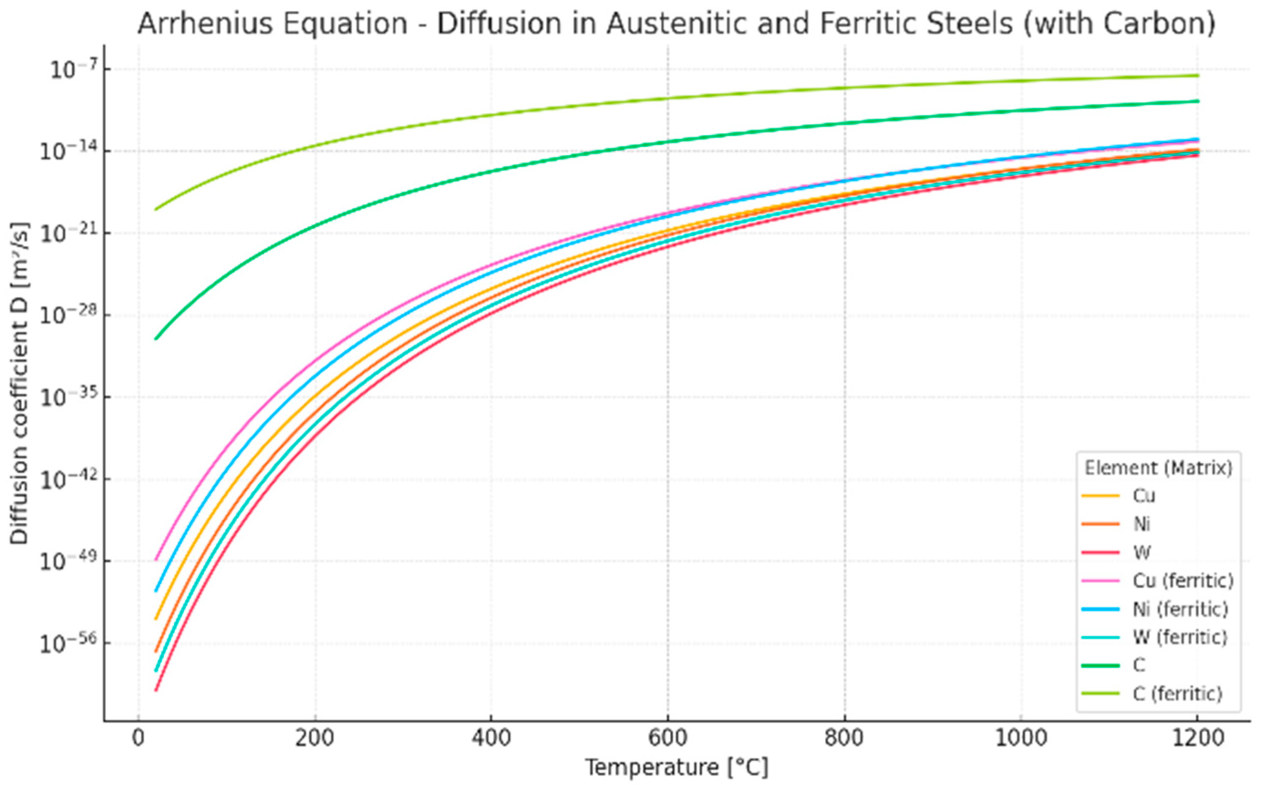
| Element | Matrix | Pre-Exponential Factor D0 [m2/s] | Activation Energy of Diffusion Q [kJ/mol] |
|---|---|---|---|
| Cu | Austenitic | 0.0001 | 280 |
| Cu | Ferritic | 0.00005 | 250 |
| Ni | Austenitic | 0.00062 | 300 |
| Ni | Ferritic | 0.0004 | 270 |
| Cr | Austenitic | 0.0025 | 310 |
| Cr | Ferritic | 0.002 | 300 |
| W | Austenitic | 0.001 | 320 |
| C | Ferritic | 0.00002 | 80 |
| C | Austenitic | 0.00002 | 142 |
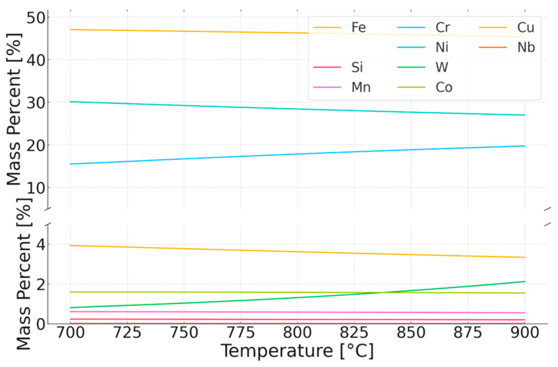
| Chemical Composition wt% | |||||||||||
|---|---|---|---|---|---|---|---|---|---|---|---|
| Volume Fraction, % | Phase | Fe | Mn | Cr | Ni | W | Co | Nb | Cu | C | N |
| 97.10 | Matrix (austenite) | 39.4 | 0.9 | 27.3 | 22.6 | 5.7 | 1.2 | 0.1 | 2.5 | 0.1 | 0.3 |
| 1.10 | (Cr. Nb)N | 4.8 | 0.1 | 68.0 | 0.5 | 10.3 | 0.0 | 7.1 | 1.5 | 7.7 | |
| 0.03 | M23 C6 | 12.1 | 0.3 | 55.7 | 1.9 | 25.3 | 0.1 | 4.6 | |||
| 0.30 | Sigma | 28.1 | 0.4 | 30.0 | 9.4 | 31.4 | 0.8 | 0.1 | |||
| Chemical Composition wt% | |||||||||||
|---|---|---|---|---|---|---|---|---|---|---|---|
| Volume Fraction, % | Phase | Fe | Mn | Cr | Ni | W | Co | Nb | Cu | C | N |
| 99.32 | Matrix (austenite) | 43.4 | 0.005 | 24.4 | 24.6 | 1 | 1.2 | 0.00052 | 2.6 | 0.01 | 0.7 |
| 0.06 | FCC (Cr. Nb)N | - | - | 13 | - | - | - | 36 | - | 15 | 33 |
Disclaimer/Publisher’s Note: The statements, opinions and data contained in all publications are solely those of the individual author(s) and contributor(s) and not of MDPI and/or the editor(s). MDPI and/or the editor(s) disclaim responsibility for any injury to people or property resulting from any ideas, methods, instructions or products referred to in the content. |
© 2025 by the authors. Licensee MDPI, Basel, Switzerland. This article is an open access article distributed under the terms and conditions of the Creative Commons Attribution (CC BY) license (https://creativecommons.org/licenses/by/4.0/).
Share and Cite
Cempura, G.; Kruk, A. Precipitation Processes in Sanicro 25 Steel at 700–900 °C: Experimental Study and Digital Twin Simulation. Materials 2025, 18, 3594. https://doi.org/10.3390/ma18153594
Cempura G, Kruk A. Precipitation Processes in Sanicro 25 Steel at 700–900 °C: Experimental Study and Digital Twin Simulation. Materials. 2025; 18(15):3594. https://doi.org/10.3390/ma18153594
Chicago/Turabian StyleCempura, Grzegorz, and Adam Kruk. 2025. "Precipitation Processes in Sanicro 25 Steel at 700–900 °C: Experimental Study and Digital Twin Simulation" Materials 18, no. 15: 3594. https://doi.org/10.3390/ma18153594
APA StyleCempura, G., & Kruk, A. (2025). Precipitation Processes in Sanicro 25 Steel at 700–900 °C: Experimental Study and Digital Twin Simulation. Materials, 18(15), 3594. https://doi.org/10.3390/ma18153594