Article

Influence of Mullite and Halloysite Reinforcement on the Ablation Properties of an Epoxy Composite

by
Robert Szczepaniak
1,*,
Michał Piątkiewicz
2,
Dominik Gryc
3,
Paweł Przybyłek
1,
Grzegorz Woroniak
4 and
Joanna Piotrowska-Woroniak
4
1
Faculty of Aviation, Polish Air Force University, Dywizjonu 303 No. 35, 08-521 Deblin, Poland
2
41 Air Training Base, Brygady Poscigowej 5, 08-521 Deblin, Poland
3
Institute of Navigation, Polish Air Force University, Dywizjonu 303 No. 35, 08-521 Deblin, Poland
4
HVAC Department, Bialystok University of Technology, Wiejska 45E, 15-351 Bialystok, Poland
*
Author to whom correspondence should be addressed.
Materials 2025, 18(15), 3530; https://doi.org/10.3390/ma18153530
Submission received: 25 June 2025 / Revised: 14 July 2025 / Accepted: 24 July 2025 / Published: 28 July 2025
(This article belongs to the Section Advanced Composites)

Abstract

This paper explores the impact of applying a powder additive in the form of halloysite and mullite on the thermal protection properties of a composite. The authors used CES R70 epoxy resin with CES H72 hardener, modified by varying the amount of powder additive. The composite samples were exposed to a mixture of combustible gases at a temperature of approximately 1000 °C. The primary parameters analyzed during this study were the temperature on the rear surface of the sample and the ablative mass loss of the tested material. The temperature increase on the rear surface of the sample, which was exposed to the hot stream of flammable gases, was measured for 120 s. Another key parameter considered in the data analysis was the ablative mass loss. The charred layer of the sample played a crucial role in this process, as it helped block oxygen diffusion from the boundary layer of the original material. This charred layer absorbed thermal energy until it reached a temperature at which it either oxidized or was mechanically removed due to the erosive effects of the heating factor. The incorporation of mullite reduced the rear surface temperature from 58.9 °C to 49.2 °C, and for halloysite, it was reduced the rear surface temperature to 49.8 °C. The ablative weight loss dropped from 57% to 18.9% for mullite and to 39.9% for halloysite. The speed of mass ablation was reduced from 77.9 mg/s to 25.2 mg/s (mullite) and 52.4 mg/s (halloysite), while the layer thickness loss decreased from 7.4 mm to 2.8 mm (mullite) and 4.4 mm (halloysite). This research is innovative in its use of halloysite and mullite as functional additives to enhance the ablative resistance of polymer composites under extreme thermal conditions. This novel approach not only contributes to a deeper understanding of composite behavior at high temperatures but also opens up new avenues for the development of advanced thermal protection systems. Potential applications of these materials include aerospace structures, fire-resistant components, and protective coatings in environments exposed to intense heat and flame.

1. Introduction

Thermal insulation for sensitive aerospace components like flight data recorders, aerodynamic surfaces, missile loads, and space shuttles is crucial for safety and efficiency during hypersonic flights. High speeds cause a significant temperature rise in heated elements. Ablative materials can create thermal barriers to manage this heat flow. Research into various ablative materials and additives has been ongoing since humans achieved high speeds in their constructions.
Currently, there is a focus on enhancing both the ablation and thermal characteristics of materials as well as their mechanical properties. Research is being conducted to understand the impact of mechanical loads and deformations on composite materials when analyzing phenomena related to the influence of heat flux [1]. Studies have examined the effects of the arrangement of individual layers in laminates and the criteria for composite failure; for instance, Griffis [2]. Dodds [3] considered additional endothermic transformations in the matrix material and the convective effect of gases generated during ablation. The results of these studies aligned with experimental findings concerning heat transfer effects but did not account for the influence of mechanical loads. Other researchers, such as Komorek et al. [4], Kucharczyk et al. [5], Wagih et al. [6], and Guerrero et al. [7], focused on similar investigations into the thermomechanical properties of epoxy composites. Materials like C/C, C/SiC, and SiC/SiC composites are preferred due to their optimal strength properties and high heat resistance [8,9,10,11]. C/SiC composites, in particular, possess good thermal resistance, adequate strength properties, oxidation resistance, and decreasing production costs [12,13,14]. Polymer coatings with ablative composite matrices, such as epoxy resins [1,2,3,15,16] or phenolic resins [17,18,19,20,21,22,23,24], along with fillers to enhance thermal stability [1,2,12,15,16,17,18,21,25,26,27], can provide improved thermal protection. However, ablative resins require reinforcement due to their porosity, low decomposition temperature, and brittleness. Research has explored reinforcement with fibers [8,9,10,11,16,17,18,28,29,30,31], powder additions [1,15,21,32,33,34], and fillings such as boards and aerogels [33,35,36,37,38,39]. Alagar et al. [40] proposed the use of Kevlar 49, and Kucharczyk et al. [41] tested aramid fibers in thermo-protective ablative castings, demonstrating that the introduction of additives can raise the melting point and enhance the thermomechanical and thermo-protective properties of the ablative composite.
Ablation is a heat and mass transfer process that leads to irreversible structural and chemical changes in a material due to physical changes and chemical reactions accompanied by heat absorption. This process is driven by external sources of thermal energy [42,43,44]. There are several physical types of ablation, including superficial wall ablation (without aerodynamic erosion on the ablation surface), wall ablation with secondary ablation processes in the ablation layer, superficial wall ablation with aerodynamic erosion on the ablation surface, and wall ablation with aerodynamic erosion on the ablation surface with secondary ablation in the ablation layer [45]. No universal model describes the processes occurring in the composite material under the influence of heat flux. It is extremely difficult to provide a detailed description of the chemical reactions and physical phenomena during combustion in the composite material [46].
During the ablation process in materials, distinct layers can be observed (see Figure 1) at the interface between the gas and solid phases, forming the ablation surface. The boundary surface that separates the ablative layer from the original material is termed the ablative front [47].
Properly utilizing the material’s ablative properties, i.e., reducing the active volume of the material not subject to ablation, requires consideration and understanding of the material’s ablative wear mechanism.
Based on [48], the adequate ablation heat of the material H is expressed by the relationship between the heat flux density and the mass ablation rate.
H = q 0 m ˙ = { T o T a c p d T + ξ c f + β H 0 } · q 0 q o q p
where:
  • m ˙ —massive ablation rate [g/s],
  • q 0 —heat flux density determined for the original (not degraded) surface at the ablation temperature [W/m2],
  • q p —emission flux density [W/m2],
  • c f —the heat of phase changes (melting, evaporation, sublimation) [J/kg],
  • c p —specific heat at constant pressure [J/kgK],
  • T a —absolute ablation temperature on the material surface [K],
  • H —gas enthalpy increase in the boundary layer [J/kg],
  • ξ —gasification coefficient of pyrolysis products,
  • β —mass exchange coefficient with air.
The thermal diffusivity of a material determines its ability to equalize temperature gradients. Therefore, developing ablative thermal protection involves finding materials with high density (ρ) and high specific heat (Cp(t)) while also having a low thermal conductivity coefficient (λ(t)); in other words, low thermal diffusivity (as referenced in [42]).
α t = λ ( t ) ρ C p ( t )
Mullite, with a high melting point of 1850 °C, is the sole stable compound in the Al2O3–SiO2 binary system [49,50]. High-purity mullite ceramic materials serve as essential raw materials in the production of functional ceramics and find extensive applications in metallurgy, energy conservation, environmental protection, and the electronics industry. This is attributed to their remarkably high-temperature strength properties, low thermal expansion coefficient, and excellent chemical stability [51,52,53,54]. The exceptional high-temperature properties of mullite render it an appealing choice for deployment in various applications, including as a matrix material for the production of high-temperature composites, a substrate in multilayer packaging and protective coatings, and an infrared transparent window specifically tailored for high-temperature applications [55,56,57,58]. Mullite is a preferred ceramic material for thermal protection systems (TPSs) due to its excellent thermal resistance, oxidation resistance, low thermal expansion coefficient, mechanical strength, high creep resistance at low and high temperatures, as well as good chemical and thermal stability [59]. Mullite matrix composites are used in various components and constructions, such as gas turbine engines (inserts, thermal shingles for combustion chambers, exhaust cones), high-efficiency furnaces, burner tubes, and heat shields for space vehicles during entry [60,61]. The addition of reinforced fibers significantly enhances the mechanical properties of the mullite and could promote electromagnetic wave absorption [62,63]. From the literature preview, it appears that using mullite in epoxy composites is uncommon.
Halloysite (Hal) is a material that has been studied for its impact on the ablative properties of epoxy composites [64,65]. It is a natural clay with a tubular structure suitable for creating hybrids/composites. Halloysite has gained attention due to its environmentally friendly nature and availability in large quantities for industrial use. Its unique chemical properties allow for the formation of new structures with other aluminosilicates, such as zeolites, while retaining its functional properties [66]. Halloysite nanotubes (HNTs) are naturally occurring aluminosilicates with a hollow tubular structure mined from natural deposits [67,68,69,70,71]. These nanotubes can be used to reinforce polymers and have a unique strengthening effect on various polymers [72,73,74,75,76,77]. Halloysite nanotubes (HNTs) allow for smooth diffusion in the polymer matrix compared to other nano-clays [78,79,80]. This makes HNTs an excellent candidate for polymer composites and has sparked significant research interest [77]. As an additive, HNTs are used to improve mechanical and/or thermal properties [81,82].
Utilizing well-dispersed nanofillers such as halloysite nanotubes in nanocomposites has enhanced fire resistance and thermal stability [83]. Halloysite nanotubes (HNTs) offer a promising alternative as flame-retardant carriers for controlling the migration of flame-retardant molecules, thereby providing long-term aging properties. A review by Jasinski et al. [66] highlighted the impact of HNTs and their derivatives on the fire-resistant properties of polymer-based composites, emphasizing the superior flame-retardant properties of halloysite nanotubes. HNTs can serve as flame retardants by forming a ceramic structure and creating a barrier against heat and mass transfer.
The mechanical properties of exfoliated clay/epoxy nanocomposites have attracted significant attention due to the properties and expanding range of applications. Numerous researchers have conducted numerical studies in this area [84,85,86,87,88,89,90,91]. For instance, Zhao et al. [88] studied the impact of micromechanics models on the prediction of the mechanical properties of short fiber composites. Khudari Bek et al. [89] presented a new mesh algorithm for investigating the elastic properties of nanocomposite polymeric materials (PNCs) using the scaled boundary finite element method (SBFEM). Shi et al. [91] conducted a study on a structurally integrated thermal protection system (ITPS) with both load capacity and thermal protection. They tested an innovative, fully composite sandwich panel with a corrugated core manufactured by hot pressing. They presented an analytical model of the composite sandwich panel based on the theory of surface ablation and transient heat transfer, which considers pyrolysis reactions, phase transitions, evaporation of quartz fibers, formation of decomposition gases, and surface ablation.
Considering the above, the authors decided to investigate the ablation properties of the epoxy composite after adding mullite and halloysite, with the aim of developing advanced thermal protection materials. This study focused on evaluating the impact of these ceramic additives on key performance indicators such as the rear surface temperature, ablative mass loss, and material thickness reduction under extreme thermal loads. The innovative aspect of this research lies in the use of mullite and halloysite as functional fillers in an epoxy matrix, which has not been widely explored in the context of high-temperature ablative applications. By comparing the effects of both additives, this study also aimed to determine their relative effectiveness and potential for optimizing composite formulations intended for aerospace, defense, or fire-resistant technologies.

2. Materials and Methods

Ablative materials have the ability to dissipate significant amounts of thermal energy through phase changes, making them ideal for protecting various components from the effects of high-temperature heat flux.
Due to the growing demand for materials resistant to degradation during prolonged exposure to elevated temperatures [26,92], an investigation was conducted to assess the impact of adding mullite and halloysite on the thermal resistance of a polymer composite. To determine the ablation properties of the tested sample structure, the following aspects were analyzed during the research process:
(1)
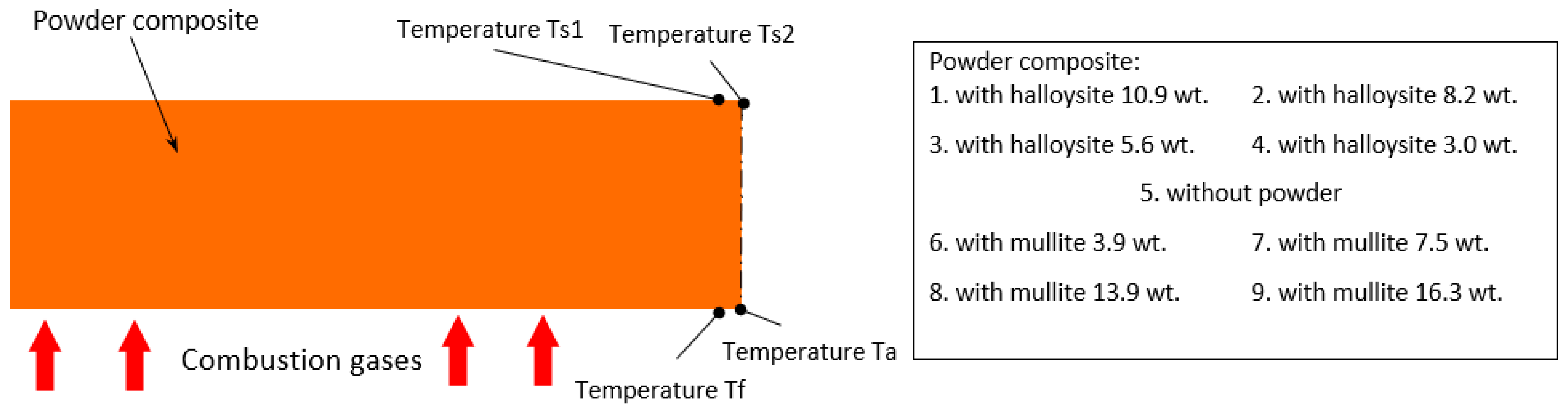
temperature of the back surface of the tested material Ts,
(2)
temperature of the ablation surface Ta,
(3)
relative ablative loss of mass Ma,
(4)
relative speed of mass ablation ma,
(5)
geometric defect of the ablation layer l.

2.1. Material Subjected to Ablation Tests

For the tests, a composite was made based on the CES R70 epoxy resin [50] cross-linked at room temperature using the CES H72 hardener [49] manufactured by SIKA. This resin is widely used, among others, for gluing, laminating, casting, and flooring systems. The density of the resin is 1.16 ± 0.02 g/cm3, and the density of the hardener is 1.02 ± 0.02 g/cm3. The working time of the resin and hardener mixture is approximately 45 min at room temperature. The manufacturer-recommended mixing ratio for the ingredients is 100:54 (CES R70H72). The filler used was mullite powder (aluminum silicate, 3Al2O3·2SiO2) (size < 45 µm) from Sigma Aldrich, along with halloysite nanopowder (Al2Si2O5(OH)4·2H2O) (diameter: 30–70 °nm × length 1–3 °μm, nanotube), also from Sigma Aldrich. The melting point of mullite is 1810 °C, with a relative density of 3.03 g/cm3. Halloysite, on the other hand, has a melting point above 1300 °C and a density of 2.53 g/cm3. Mullite (porcellanite) is a constituent mineral in thermally metamorphosed rock known as porcellanite [52]. Halloysite is a natural nanoclay with the same chemical composition as the more common kaolinite clay. Nine series of samples were prepared, each consisting of three pieces, differing in the amount of powder additive used (see Table 1). To ensure proper dispersion of the ingredients, due to the significant differences in the densities of the individual materials, the powders were added a few minutes before the resin reached its gelation point. After the powder was added, manual mixing was performed, followed by the application of ultrasonic treatment to ensure homogeneous dispersion of the additives and effective degassing.
Then, the material was gravity-cast into silicone molds with a diameter of about 38 mm and a thickness of about 12 mm. After a 7-day hardening period at room temperature, they were embedded in a plasterboard to isolate the back surface of the tested sample from the heat of the flame. For this purpose, a high-temperature sealant Ceresit CS 38 from Ceresit Co. Henkel Poland, Bydgoszcz, Poland was used, up to 1500 °C. After applying the sealant, we waited about 12 h for it to harden.
During their production, thermocouples were placed in each sample to measure the temperature during the tests. The thermocouples were mounted on the back surface of the sample (temperature measurements Ts1 and Ts2) and one control element was attached to check the rate of the temperature increase on the front surface Tf (see Figure 2), which recorded the temperature only for the first seconds of measurement due to the rapid burning due to the direct impact of the flammable gas stream. The temperature of the ablation surface was also measured using an optical pyrometer Ta.

2.2. Test Stand and Research Methodology

Due to the temperature range, it was decided to measure with type J thermocouples on the rear surface of the composite and the type K on the surface on the side of the heat source (for control purposes). At the authors’ test stand (see Figure 3), samples produced using the previously described method were exposed to a stream of hot gases (approximately 1000–1100 °C). The test duration was limited to approximately 120 s for each sample.
To achieve a directed and focused flame, the burner was placed inside the "ablation gun," which consists of a ceramic tube (see Figure 4). The temperature was recorded using a National Instruments device, model SCB, Austin, TX, USA, in conjunction with National Instruments LabView 2015 software, Austin, TX, USA. The temperature of the ablation surface, which was exposed to the flame of the tested sample, was measured using an Optris pyrometer, model CT, Berlin, Germany, equipped with a laser pointer for precise targeting of the measurement site (see Figure 4). To ensure uniformity in the temperature distribution on the back surface of the sample, an FLIR SYSTEMS AB, FLIR i60, thermal imaging camera Arlington, VA, USA was utilized. Prior to conducting the tests, the measuring system was calibrated to ensure accuracy. Additionally, the optimum distance from the ablation gun to the ablation surface was determined to achieve a target temperature of approximately 1000 °C.

3. Results and Discussion

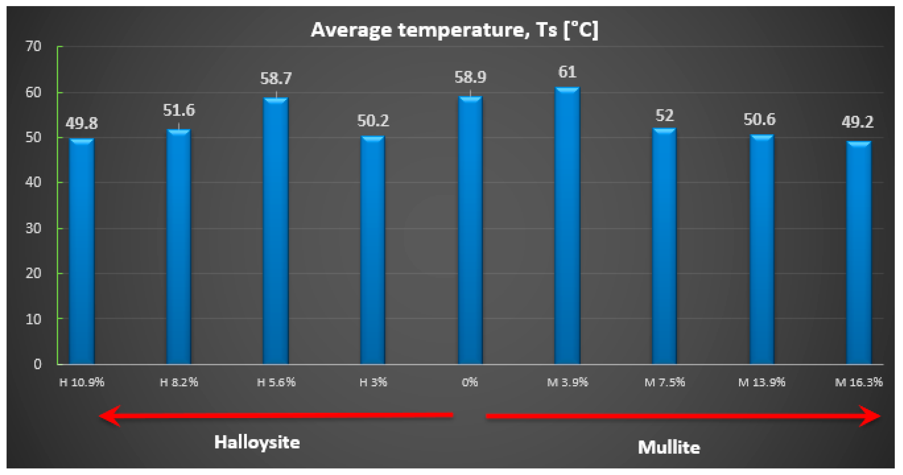
3.1. Measurement of the Temperature of the Ablation Surface and the Temperature on the Back Surface of the Composite

The most crucial parameter for analyzing the effect of powder additives on the ablative thermal protective properties of the powder-reinforced polymer composite is the change in temperature on the back surface of the tested material (denoted as Ts). To compare the influence of these additives, the authors recorded the temperature at the last second of the Ts test, specifically after 120 s of heat flow exposure to the tested material. The average temperature values for the back surface are presented (see Figure 5).
Based on the obtained measurement results, it can be seen that when adding a powder additive in the form of halloysite and mullite, only when it reaches approximately 8% is a drop in the rear surface temperature visible (see Figure 5). The best thermal protection properties, and therefore the lowest temperature value for the back wall of the sample, are seen for composites with an increased amount of the additive. Their average temperature for the back surface of the wall was ~50 °C.
Figure 6 shows an example of the temperature change over time recorded for sample 5.3, which consisted of unmodified epoxy resin without powder addition (see Figure 6). The temperature was measured on the rear surface of the sample during exposure to a high-temperature gas stream for 120 s. This temperature profile serves as a reference for evaluating the thermal insulation performance of composites modified with ceramic fillers. The relatively rapid and continuous increase in the rear surface temperature reflects the limited thermal protection capability of the base material in the absence of additives. In addition to the rear surface temperature, the results of the non-contact surface temperature measurements of the ablation zone performed using a pyrometer, as well as the position of the ablation front over time, are also presented. These measurements provide a more comprehensive view of the thermal response and material degradation mechanisms under high-temperature exposure.
For control purposes, an FLIR i60 thermal imaging camera was used to check the uniformity of the temperature field distribution on the back surface while testing the ablation properties of the composites. This camera allows for detailed imaging of the temperature variations. Figure 7 illustrates an example of the temperature distribution on the back surface of the tested material, specifically sample 5.3 (a composite without powder additives). Temperature readings from a point close to the center of the sample, where thermocouples were also placed, were taken every 30 s. These measured values were then plotted on a temperature distribution graph (see Figure 7 and Figure 8).
There is a significant similarity between the results obtained via these two research techniques. Two measurements from different samples are presented: one from a sample made solely of resin with a hardener and no powder addition (see Figure 7), and the other from a sample with halloysite added (see Figure 8), which demonstrates a different nature of temperature changes on the back surface.
Analyzing the results of testing the temperature increase on the rear surface for the composite with powder additive, smaller values can be noticed compared to the composite without the additive. Observing the photos obtained from a thermal imaging camera, one can notice more significant thermal blockage in the material with the addition of powder (see Figure 8).

3.2. Changes in Mass and Geometric Properties of Samples During Ablation Tests

The relative ablative loss of mass (expressed as a percentage) was determined by analyzing the changes in the weight of the examined samples before and after the heat resistance tests. The obtained results are presented (see Figure 9), while the relative speed of mass loss is shown in mg/s (see Figure 10). Individual data for each sample are detailed (Table 2).
The highest ablation mass loss was recorded for the composite material without powder addition (57%) or with a small amount, especially mullite (64%), which corresponds to a mass ablation rate of 78 mg/s and 77 mg/s mass loss during the tests, so the changes were not recorded compared to the composite without the addition. In the case of the addition of halloysite, regardless of the amount, the ablation mass loss was about 40% and the ablation rate was about 56 mg/s, which is a reduction of about 30% compared to the composite without the addition.
The geometric reduction of the composite layer was also assessed. The values (see Figure 11a) represent the average thickness loss from each sample. In the case of mullite, there is a noticeable reduction in the thickness with the amount of additive (from 7.45 mm for composites without additive to only about 3 mm for 13.9% and 16.3% of mullite addition). However, for halloysite, with the addition of 10.9%, the thickness changes amounted to approximately 4 mm. There is a significant difference in the structure of the material after burning with the addition of mullite and halloysite (see Figure 11b–e).

4. Conclusions

Conducting ablation tests on the thermal protective properties of the powder composite with the addition of mullite and halloysite enabled the estimation of the temperature changes occurring on the back surface of the samples. A pyrometer was used to determine the approximate temperature of the front surface during the tests, while a thermal camera captured the temperature distribution on the back surface of the tested material. The use of double thermocouples facilitated a more accurate measurement of the rear surface temperature, addressing the uneven distribution confirmed by visual measurements from the thermal imaging camera. When feasible, positioning the thermocouples on the central surface allowed for precise readings of the desired temperature increases.
Based on this study, it can be concluded that the incorporation of powder reinforcement significantly enhanced the thermo-protective properties of the composite, particularly in terms of the mass ablation rate and ablative loss parameters, due to the increased proportion of the mullite additive. The addition of mullite and halloysite resulted in a notable reduction in the ablation parameters compared to the base material:
(1)
Rear surface temperature from 58.9 °C to 49.2 °C (mullite) and to 49.8 °C (halloysite).
(2)
Ablative weight loss from 57% to 18.9% (mullite) and up to 39.9% (halloysite).
(3)
Speed of mass ablation from 77.9 mg/s to 25.2 mg/s (mullite) and up to 52.4 mg/s (halloysite).
(4)
Loss of layer thickness from 7.4 mm to 2.8 mm (mullite) and up to 4.4 mm (halloysite).
The analysis of the obtained results from the experimental tests on ablative thermal protective properties proved a significant improvement in the thermal protective properties of the material. However, increasing the amount of mullite additive dynamically improved the ablation properties from just 7% of the additive amount, while adding halloysite improved the properties, but in a less dynamic way.
The obtained experimental results and their interpretation allow us to conclude that ablative coatings based on polymer composites with powder additives effectively influence thermal protection during short-term exposure to flammable gas streams. It is assumed that the use of a larger amount of the additive would result in an even greater reduction in temperature compared to the sample without the additive. Summarizing the obtained results, it should be noted that the impact of the use of the additive on the ablation properties was noted, but the differences are not very significant; therefore, in the future, additional tests should be carried out with a much higher share of the additive in the dispersion composite.
In the following steps, we plan to use computer vision to automatically and quantitatively analyze the surface char morphology, ablation front progression, and defect evolution from thermal and optical images. This will enable high-throughput, objective assessments beyond manual or single-point measurements. As future directions for our research, robust and efficient vision-based models could be employed, such as DeepLab [93]. DeepLabv3 is a deep neural network (DNN) architecture designed for semantic segmentation tasks. It uses atrous (dilated) convolutions to control receptive fields and feature map resolutions without increasing the total number of parameters. Another key feature is atrous spatial pyramid pooling, which effectively extracts multi-scale features that provide valuable information for segmentation. Overall, the network can generate dense feature maps with rich long-range information, allowing for accurate image segmentation. This technique involves labeling each pixel in an image with a class that corresponds to what that pixel represents. Another useful model is EfficientNet [94], which employs the idea of progressive learning. This means that, although training begins with small image sizes, the sizes increase gradually, addressing the slowdown in training speed that occurs with larger images.

Author Contributions

Conceptualization, R.S. and P.P.; Methodology, R.S. and P.P.; Validation, R.S., M.P. and D.G.; Formal analysis, R.S. and G.W.; Investigation, R.S., M.P., D.G., P.P., G.W. and J.P.-W.; Resources, R.S., M.P. and P.P.; Data curation, R.S., M.P., D.G., P.P., G.W. and J.P.-W.; Writing—original draft preparation, R.S., P.P. and G.W.; Writing—review and editing, R.S., P.P., G.W. and J.P.-W.; Visualization, R.S., M.P., D.G., P.P., G.W. and J.P.-W.; Supervision, R.S.; Project administration, R.S., G.W.; Funding acquisition, R.S., G.W. and J.P.-W. All authors have read and agreed to the published version of the manuscript.

Funding

This research received no external funding.

Institutional Review Board Statement

Not applicable.

Informed Consent Statement

Not applicable.

Data Availability Statement

The original contributions presented in this study are included in the article. Further inquiries can be directed to the corresponding authors.

Acknowledgments

This work has been accomplished under the research project no. WZ/WB-IIS/6/2023 and WZ/WB-IIS/7/2023 at the Bialystok University of Technology.

Conflicts of Interest

The authors declare no conflicts of interest.

References

  1. Chen, J.K.; Sun, C.T.; Chang, C.I. Failure analysis of a graphite/epoxy laminate subjected to combined thermal and mechanical loading. J. Compos. Mater. 1985, 19, 408–423. [Google Scholar] [CrossRef]
  2. Griffis, C.; Nemes, J.A.; Stonesifer, F.R.; Chang, C.I. Degradation in strength of laminated composites subjected to intense heating and mechanical loading. J. Compos. Mater. 1986, 20, 216–235. [Google Scholar] [CrossRef]
  3. Dodds, N. Fire behavior of composite laminates. Compos. Part A Appl. Sci. Manuf. 2000, 31, 689–702. [Google Scholar] [CrossRef]
  4. Komorek, A.; Przybyłek, P.; Kucharczyk, W.; Krzyżak, A. Effect of grain fillers on the thermo-protective and the strength properties of epoxy-matrix composites based on aramid fabrics used to the aviation requirements. Logistics 2014, 45, 3030–3039. (In Polish) [Google Scholar]
  5. Kucharczyk, W.; Bakar, M.; Żurowski, W.; Białkowska, A.; Opara, T.; Stawarz, S. Influence of carbon nanotubes, resin matrix and technology of mixture homogenization on ablative and dynamic mechanical properties of epoxy nanocomposites. Compos. Struct. 2022, 2801, 14801. [Google Scholar] [CrossRef]
  6. Wagih, A.; Sebaey, T.A.; Yudhanto, A.; Lubineau, G. Post-impact flexural behavior of carbon-aramid/epoxy hybrid composites. Compos. Struct. 2020, 239, 112022. [Google Scholar] [CrossRef]
  7. Guerrero, J.M.; Mayugo, J.A.; Costa, J.; Turon, A. Failure of hybrid composites under longitudinal tension: Influence of dynamic effects and thermal residual stresses. Compos. Struct. 2020, 233, 111732. [Google Scholar] [CrossRef]
  8. Krenkel, W.; Berndt, F. C/C–SiC composites for space applications and advanced friction systems. Mater. Sci. Eng. A 2005, 412, 177–181. [Google Scholar] [CrossRef]
  9. Krenkel, W.; Hausherr, J.M.; Reimer, T.; Friess, M. Design manufacture and quality assurance of C/C–SiC composites for space transportation systems. Ceram. Eng. Sci. Proc. 2004, 25, 49–58. [Google Scholar] [CrossRef]
  10. Chen, R.; Zhang, Y.; Zhang, J.; Zhu, X. MoSi2 modified HfC coating for the ablation protection of SiC-coated C/C composites: Ablation resistance and behavior. Corros. Sci. 2022, 205, 110418. [Google Scholar] [CrossRef]
  11. Zhang, X.; Du, B.; Hu, P.; Cheng, Y.; Han, J. Thermal response, oxidation and ablation of ultra–high temperature ceramics, C/SiC, C/C, graphite and graphite–ceramics. J. Mater. Sci. Technol. 2022, 102, 137–158. [Google Scholar] [CrossRef]
  12. Ogasawara, T.; Aoki, T.; Hassan, M.S.A.; Mizokami, Y.; Watanabe, N. Ablation behavior of SiC fibre/carbon matrix composites under simulated atmospheric re-entry conditions. Compos. Part A 2011, 42, 221–228. [Google Scholar] [CrossRef]
  13. Mungiguerra, S.; Silvestroni, L.; Savino, R.; Zoli, L.; Esser, B.; Lagos, M.; Sciti, D. Qualification and reusability of long and short fibre-reinforced ultra-refractory composites for aerospace thermal protection systems. Corros. Sci. 2022, 195, 109955. [Google Scholar] [CrossRef]
  14. Liu, X.-S.; Fu, Q.-G.; Wang, H.; Song, Q. Microstructure, thermophysical property and ablation behavior of high thermal conductivity carbon/carbon composites after heat-treatment. Chin. J. Aeronaut. 2020, 33, 1541–1548. [Google Scholar] [CrossRef]
  15. Bakar, M.; Kucharczyk, W.; Stawarz, S. Investigation of thermal and ablative properties of modified epoxy resins. Polym. Polym. Compos. 2016, 24, 617–623. [Google Scholar] [CrossRef]
  16. Zhang, H.; Guo, L.; Liu, H.; Zhang, Y.; Fu, O.; Yin, H.; Li, H. Advanced anti-ablation C/C composites: Structural design strategies and future perspective. Mater. Today 2024, 80, 710–736. [Google Scholar] [CrossRef]
  17. Wang, S.; Wang, L.; Song, W.; Li, C.; Fan, W.; Bian, C.; Zhang, C.; Jing, X. The aryl-boron phenolic resins with super ablation properties for resin-transfer molding process of three-dimensional fabric. Polym. Degrad. Stab. 2023, 208, 110252. [Google Scholar] [CrossRef]
  18. Bahramian, A.R.; Kokabi, M. Ablation mechanism of polymer layered silicate nanocomposite heat shield. J. Hazard. Mater. 2008, 166, 445–454. [Google Scholar] [CrossRef]
  19. Shi, L.; Chew, M.Y.L. A review of fire processes modelling of combustible materials under external heat flux. Fuel 2013, 106, 30–50. [Google Scholar] [CrossRef]
  20. Summers, P.T.; Lattimer, B.Y.; Case, S.; Feih, S. Sensitivity of thermo-structural model for composite laminates in fire. Compos. Part A 2021, 43, 783–792. [Google Scholar] [CrossRef]
  21. Kucharczyk, W.; Przybyłek, P.; Opara, T.A. Investigation of the thermal protection ablative properties of thermosetting composites with powder fillers: The corundum Al2O3 and the carbon powder C. Pol. J. Chem. Technol. 2013, 15, 49–53. [Google Scholar] [CrossRef]
  22. Bahramian, A.R. Effect of external heat flux on the thermal diffusivity and ablation performance of carbon fibre reinforced novolac resin composite. Iran. Polym. J. 2013, 22, 579–589. [Google Scholar] [CrossRef]
  23. Pulci, G.; Tirillň, J.; Marra, F.; Fossati, F.; Bartuli, C.; Valente, T. Carbon–phenolic ablative materials for re-entry space vehicles: Manufacturing and properties. Compos. Part A 2010, 41, 1483–1490. [Google Scholar] [CrossRef]
  24. Yang, X.; Li, L.; Shi, M.; Huang, Z.; Deng, Z. Ablation resistance and high-temperature insulation capacity of TiB2-B4C modified Al-coated carbon fibre/boron phenolic resin ceramizable composites. Ceram. Int. Part B 2024, 50, 54654–54665. [Google Scholar] [CrossRef]
  25. Kucharczyk, W. Investigation of the Thermal Protection Ablative Properties of Polymer Composites with Powder Fillers. Ph.D. Thesis, Technical University of Radom, Radom, Poland, 2007. (In Polish). [Google Scholar]
  26. Butler, B.D.; Winter, M.; Panerai, F.; Martin, A.; Bailey, S.C.; Stackpoole, M.; Denehy, P.M.; Splinter, S. Characterization of candidate materials for remote recession measurements of ablative heat shield materials. In Proceedings of the 54th AIAA Aerospace Sciences Meeting, San Diego, CA, USA, 4–8 January 2016. [Google Scholar] [CrossRef]
  27. Czigany, T. Discontinuous basalt fibre-reinforced hybrid composites. In Polymer Composites from Nano- to Macro Scale; Springer: New York, NY, USA, 2005; Chapter 17; Part IV; p. 309. Available online: https://link.springer.com/book/10.1007/b137162 (accessed on 20 March 2025).
  28. Thapliyal, P.C.; Singh, K. Aerogels as Promising Thermal Insulating Materials: An Overview. J. Mater. 2014, 2014, 127049. [Google Scholar] [CrossRef]
  29. Beaudet, J.; Benoit, G.; Cormier, J.; Dragon, A.; Rollin, M. Ablation properties of C fibers and SiC fibers reinforced glass ceramic matrix composites upon oxyacetylene torch exposure. Mater. Sci. Appl. 2011, 2, 1399–1406. [Google Scholar] [CrossRef]
  30. Zhang, Z. Thermo-Mechanical Behavior of Polymer Composites Exposed to Fire. Ph.D. Thesis, Virginia Polytechnic Institute and State University, Blacksburg, VA, USA, 2010. Available online: https://polymerandfire.wordpress.com/wp-content/uploads/2014/09/zhang_z_d_2010.pdf (accessed on 25 March 2025).
  31. Bogoeva-Gaceva, G.; Dimeski, D.; Srebrenkoska, V. Composite material based on an ablative phenolic resin and carbon fibers. J. Serbian Chem. Soc. 2009, 74, 441–453. [Google Scholar] [CrossRef]
  32. Ma, J.; Kou, S.; Yang, S.; Liu, Y.; Luan, C.; Wang, P.; Fan, S. Ablation performance of C/C-ZrC-SiC composites with in-situ YSi2-doped ZrC-SiC-ZrSi2 coating under oxyacetylene torch. Corros. Sci. 2022, 209, 110802. [Google Scholar] [CrossRef]
  33. He, D.; Jiao, F.; Ou, D.; Gao, H.; Wu, J. Thermal insulation and anti-vibration properties evaluation of modified epoxy resin-based thermal protection coatings in arc-jet. Prog. Org. Coat. 2022, 173, 107158. [Google Scholar] [CrossRef]
  34. Krzyzak, A.; Kucharczyk, W.; Gaska, J.; Szczepaniak, R. Ablative test of composites with epoxy resin and expanded perlite. Compos. Struct. 2018, 202, 978–987. [Google Scholar] [CrossRef]
  35. Ma, H.; Zheng, X.; Luo, X.; Yi, Y.; Yang, F. Simulation and Analysis of Mechanical Properties of Silica Aerogels: From Rationalization to Prediction. Materials 2018, 11, 214. [Google Scholar] [CrossRef]
  36. Natali, M.; Monti, M.; Puglia, D.; Kenny, J.M.; Torre, L. Ablative properties of carbon black and mwnt/phenolic composites: A comparative study. Compos. Part A 2012, 43, 174–183. [Google Scholar] [CrossRef]
  37. Cheng, H.; Xue, H.; Hong, C.H.; Zhang, X. Preparation. mechanical. thermal and ablative properties of lightweight needled carbon fibre felt/phenolic resin aerogel composite with a bird’s nest structure. Compos. Sci. Technol. 2010, 140, 63–72. [Google Scholar] [CrossRef]
  38. Wang, H.; Pan, Y.; Jin, X.; Wu, C.; Huang, H.; Yan, X.; Hong, C.; Zhang, X. Gradient fiber-reinforced aerogel composites using surface ceramicizable-resin densification with outstanding ablation resistance for high-temperature thermal protection. Compos. Sci. Technol. 2022, 230, 109798. [Google Scholar] [CrossRef]
  39. Nabipour, H.; Nie, S.; Wang, X.; Song, L.; Hu, Y. Zeolitic imidazolate framework-8/polyvinyl alcohol hybrid aerogels with excellent flame retardancy. Compos. Part A 2020, 129, 105720. [Google Scholar] [CrossRef]
  40. Alagar, M.; Kumar, A.; Mahesh, K.P.O.; Dinakaran, K. Studies on thermal and morphological characteristics of E-glass/Kevlar 49 reinforced siliconized epoxy composites. Eur. Polym. J. 2000, 36, 2449–2454. [Google Scholar] [CrossRef]
  41. Kucharczyk, W.; Dusiński, D.; Żurowski, W.; Gumiński, R. Effect of composition on ablative properties of epoxy composites modified with expanded perlite. Compos. Struct. 2018, 183, 654–662. [Google Scholar] [CrossRef]
  42. Zhang, S.; Sun, W.; Zhan, Z.; Wen, Q.; Zhang, H.; Xiong, X. Ablation and insulation properties of hybrid carbon-quartz fiber fabric reinforced magnesium phosphate cement composite. Constr. Build. Mater. 2025, 464, 140122. [Google Scholar] [CrossRef]
  43. Jackowski, A. Flat wall ablation in the conditions of erosive lifting of the ablation layer. WAT Bull. 1986, 460, 23–33. (In Polish) [Google Scholar]
  44. Szczepaniak, R.; Kozun, G.; Przybylek, P.; Komorek, A.; Krzyzak, A.; Woroniak, G. The effect of the application of a powder additive of a phase change material on the ablative properties of a hybrid composite. Compos. Struct. 2021, 256, 113041. [Google Scholar] [CrossRef]
  45. Przybyłek, P. Analysis of the Possibilities to Increase the Heat Resistance of Flight Recorders by Using Covers Made of Ablation Polymer Composites. Ph.D Thesis, University of Technology and Humanities in Radom, Radom, Poland, 2018. (In Polish). [Google Scholar]
  46. Jurkowski, B.; Rydarowski, H. Polymer Materials with Reduced Flammability; Scientific Publishing House of the Institute of Sustainable Technologies: Radom, Poland, 2012. (In Polish) [Google Scholar]
  47. Kucharczyk, W. Some ablative properties of epoxy composites used for thermoprotection. Chem. Ind. 2010, 89, 1673–1676. Available online: https://www.researchgate.net/publication/294711350_Some_ablative_properties_of_epoxy_composites_used_for_thermoprotection (accessed on 5 February 2025). (In Polish).
  48. Komorek, A.; Przybyłek, P. Protective enclosures for avionic equipment with coatings based on components with ablative properties. Assem. Technol. Autom. 2010, 4, 21–26. (In Polish) [Google Scholar]
  49. Routschka, G. Pocket Manual Refractory Materials: Basics-Structures-Properties; Vulkan-Verlag GmbH: Essen, Germany, 2004; ISBN 3802731549. [Google Scholar]
  50. Duval, D.J.; Risbud, S.H.; Shackelford, J.F. Mullite. In Ceramic and Glass Materials; Shackelford, J.F., Doremus, R.H., Eds.; Springer: Boston, MA, USA, 2008. [Google Scholar] [CrossRef]
  51. Li, S.; Xin, J.; Chen, R. Achieving high strength and low thermal conductivity: Additive manufacturing of mullite lightweight refractory. Ceram. Int. 2024, 50, 27880–27888. [Google Scholar] [CrossRef]
  52. Zhao, F.; Ge, T.; Liu, X.; Gao, J.; Chen, L. Transient liquid phase diffusion process for porous mullite ceramics with excellent mechanical properties. Ceram. Int. 2018, 44, 19123–19130. [Google Scholar] [CrossRef]
  53. Li, C.X.; Zhou, Y.; Tian, Y.M.; Zhao, Y.Y.; Chai, Y.S. Preparation and characterization of mullite whisker reinforced ceramics made from coal fly ash. Ceram. Int. 2019, 45, 5613–5616. [Google Scholar] [CrossRef]
  54. da Silva, V.J.; de Almeida, E.P.; Goncalves, W.P.; da Nobrega, R.B.; de Neves, G.A.; De Araujo, G.; de Lira, H.L.; Menezes, R.R.; de Santana, L.N.L. Mineralogical and dielectric properties of mullite and cordierite ceramics produced using wastes. Ceram. Int. 2019, 45, 4692–4699. [Google Scholar] [CrossRef]
  55. Qing, M.; He, Q.; Zhang, X.; Wang, Y.; Yin, X. Ablation behaviours of C/C-ZrC-SiC-mullite composites with varying mullite content under high-temperature oxidizing gas flow. Mater. Charact. 2025, 221, 114749. [Google Scholar] [CrossRef]
  56. Huang, Y.; Cheng, X.; Chang, X.; Liu, H.; Surmenev, R.A.; Yu, J.; Liu, Y.-T.; Ding, B. Highly oriented mullite nanofiber membranes with high tensile strength for high-temperature thermal insulation. Compos. Commun. 2025, 56, 102369. [Google Scholar] [CrossRef]
  57. Carvalho, R.G.; Oliveira, F.J.; Silva, R.F.; Costa, F.M. Mechanical behaviour of zirconiamullite directionally solidified eutectics. Mater. Des. 2014, 61, 211–216. [Google Scholar] [CrossRef]
  58. Congxuan, S.; Koudama, T.D.; Wu, X.; Shen, X.; Cui, S.; Chen, X. Rational design of a novel mullite aerogel with extremely high mechanical strength and anti-oxidation behavior for advanced thermal protection in extreme environments. J. Eur. Ceram. Soc. 2024, 44, 1761–1771. [Google Scholar] [CrossRef]
  59. Chen, S.G.; Ma, Q.S.; Liu, W.D.; Liu, H. Progress in the research of mullite ceramic matrix composites. J. Ceram. 2012, 32, 615–620. (In Chinese) [Google Scholar]
  60. Schneider, H.; Schreuer, J.; Hildmann, B. Structure and properties of mullite—A review. J. Eur. Ceram. Soc. 2008, 28, 329–344. [Google Scholar] [CrossRef]
  61. Jiao, X.; Tan, Q.; He, Q.; Qing, M.; Wang, Y.; Yin, X. Cyclic ablation behavior of mullite-modified C/C-HfC-SiC composites under an oxyacetylene flame at about 2400 °C. J. Eur. Ceram. Soc. 2023, 43, 4309–4321. [Google Scholar] [CrossRef]
  62. Kostopoulos, V.; Loutas, T.H.; Kontsos, A.; Sotiriadis, G.; Pappas, Y.Z. On the identification of the failure mechanisms in oxide/oxide composites using acoustic emission. NDT E Int. 2003, 36, 571–580. [Google Scholar] [CrossRef]
  63. Jiang, J.; Yan, L.; Li, J.; Zhang, C.; Hu, X.; Guo, A.; Du, H.; Liu, J. Lightweight and resilient SiBCNa/mullite/SiCnw composite for thermal insulation and electromagnetic wave absorption. Ceram. Int. 2025, 51, 2315–2323. [Google Scholar] [CrossRef]
  64. Jasinski, E.; Bounor-Legaré, V.; Taguet, A.; Beyou, E. Influence of halloysite nanotubes onto the fire properties of polymer based composites: A review. Polym. Degrad. Stab. 2021, 183, 109407. [Google Scholar] [CrossRef]
  65. Sadjadi, S. Halloysite-based hybrids/composites in catalysis. Appl. Clay Sci. 2020, 189, 105537. [Google Scholar] [CrossRef]
  66. Danyliuk, N.; Tomaszewska, J.; Tatarchuk, T. Halloysite nanotubes and halloysite-based composites for environmental and biomedical applications. J. Mol. Liq. 2020, 309, 113077. [Google Scholar] [CrossRef]
  67. Gaaz, T.S.; Sulong, A.B.; Kadhum, A.A.H.; Nassir, M.H.; Al-Amiery, A.A. Optimizing physio-mechanical properties of halloysite reinforced polyurethane nanocomposites by Taguchi approach. Sci. Adv. Mater. 2017, 9, 949–961. [Google Scholar] [CrossRef]
  68. Ruan, L.; Hu, D.; Pan, Z.; Zhang, X.; Yu, K.; Ma, W. Novel eco-friendly bio-nano flame retardant via the electrostatic-driven hybridization of natural halloysite nanotubes and phytic acid for superior fire safety of epoxy composites. Compos. Commun. 2024, 51, 102055. [Google Scholar] [CrossRef]
  69. Gaaz, T.S.; Sulong, A.B.; Kadhum, A.A.H.; Nassir, M.H.; Al-Amiery, A.A. Impact of sulfuric acid treatment of halloysite on physico-chemic property modification. Materials 2016, 9, 620. [Google Scholar] [CrossRef]
  70. Gaaz, T.S.; Sulong, A.B.; Akhtar, M.N.; Kadhum, A.A.H.; Mohamad, A.B.; Al-Amiery, A.A. Properties and applications of polyvinyl alcohol, halloysite nanotubes and their nanocomposites. Molecules 2015, 20, 22833–22847. [Google Scholar] [CrossRef] [PubMed]
  71. Rooj, S.; Das, A.; Heinrich, G. Tube-like natural halloysite/fluoroelastomer nanocomposites with simultaneous enhanced mechanical. dynamic mechanical and thermal properties. Eur. Polym. J. 2011, 47, 1746–1755. [Google Scholar] [CrossRef]
  72. Hu, S.L.; Li, Y.-M.; Fang, H.-P.; Deng, Y.; Wang, D.-Y. Organic-inorganic hybrid modified the halloysite nanotube: Toward vinyl ester resin composites with enhanced flame retardance and mechanical property. Colloids Surf. A Physicochem. Eng. Asp. 2024, 697, 134412. [Google Scholar] [CrossRef]
  73. Liu, Y.; Wang, J.; Yue, H.; Du, Z.; Cheng, X.; Wang, H.; Cheng, F.; Du, X. Flame-retardant phytic acid–decorated thermoplastic starch/halloysite nanotube composite films with enhanced mechanical strength and excellent barrier properties. Carbohydr. Polym. 2024, 323, 121465. [Google Scholar] [CrossRef]
  74. Ahamad, A.; Kumar, P.; Kumar, B. Development of epoxy/flyash composites containing halloysite nanotubes: Mechanical, morphological, and thermal degradation kinetics. J. Indian Chem. Soc. 2024, 101, 101476. [Google Scholar] [CrossRef]
  75. Du, M.; Guo, B.; Lei, Y.; Liu, M.; Jia, D. Carboxylated butadiene-styrene rubber/halloysite nanotube nanocomposites: Interfacial interaction and performance. Polymer 2008, 49, 4871–4876. [Google Scholar] [CrossRef]
  76. Gaaz, T.S.; Sulong, A.B.; Kadhum, A.A.H.; Nassir, M.H.; Al-Amiery, A.A. Surface improvement of halloysite nanotubes. Appl. Sci. 2017, 7, 291. [Google Scholar] [CrossRef]
  77. Liu, M.; Guo, B.; Du, M.; Chen, F.; Jia, D. Halloysite nanotubes as a novel β-nucleating agent for isotactic polypropylene. Polymer 2009, 50, 3022–3030. [Google Scholar] [CrossRef]
  78. Zhong, L.; Li, T.; Zhang, J.; Wang, J.; Zhang, D. Simultaneously improving the flame retardancy and toughness of epoxy composites with hyperbranched phosphorus-containing polysiloxane functionalized halloysite nanotubes. Eur. Polym. J. 2022, 179, 111564. [Google Scholar] [CrossRef]
  79. Marney, D.C.O.; Russell, L.J.; Wu, D.Y.; Nguyen, T.; Cramm, D.; Rigopoulos, N.; Wright, N.; Greaves, M. The suitability of halloysite nanotubes as a fire retardant for nylon 6. Polym. Degrad. Stab. 2008, 93, 1971–1978. [Google Scholar] [CrossRef]
  80. Tierrablanca, E.; Romero-García, J.; Roman, P.; Cruz-Silva, R. Biomimetic polymerization of aniline using hematin supported on halloysite nanotubes. Appl. Catal. A Gen. 2010, 381, 267–273. [Google Scholar] [CrossRef]
  81. Guo, B.; Zou, Q.; Lei, Y.; Du, M.; Liu, M.; Jia, D. Crystallization behavior of polyamide 6/halloysite nanotubes nanocomposites. Thermochim. Acta 2009, 484, 48–56. [Google Scholar] [CrossRef]
  82. Wang, S.; Li, J.; Wang, W.; Wang, X.; Li, H.; Sun, J.; Fei, B.; Gu, X.; Zhang, S. Silicone filled halloysite nanotubes for polypropylene composites: Flame retardancy, smoke suppression and mechanical property. Compos. Part A Appl. Sci. Manuf. 2021, 140, 106170. [Google Scholar] [CrossRef]
  83. Barrientos-Ramírez, S.; de Oca-Ramírez, G.M.; Ramos-Fernández, E.V.; Sepúlveda-Escribano, A.; Pastor-Blas, M.M.; González-Montiel, A. Surface modification of natural halloysite clay nanotubes with aminosilanes. Application as catalyst supports in the atom transfer radical polymerization of methyl methacrylate. Appl. Catal. A Gen. 2011, 406, 22–33. [Google Scholar] [CrossRef]
  84. Cao, S.; Fu, T.; Tao, R.; Mao, Y.; Hou, S. Homogenization-based analysis of pyrolysis and mechanical degradation of ablative silica fiber-reinforced phenolic resin composites. Int. J. Heat Mass Transf. 2025, 236, 126328. [Google Scholar] [CrossRef]
  85. Wang, H.; Ji, R.; Xiao, G.; Qu, Z. Pore scale visualization of thermal-fluid-structural evolution in the ablation of carbon/carbon composites. Aerosp. Sci. Technol. 2022, 130, 107924. [Google Scholar] [CrossRef]
  86. Wang, T.; Li, W.; Zhang, Z.; Liang, H.; Xu, Y.; Xu, L.; Huang, H. Analysis of the integrated performance of hybrid fiber-reinforced polymer composite used for thermal protection based on a dual-scale ablation model. Aerosp. Sci. Technol. 2024, 145, 108831. [Google Scholar] [CrossRef]
  87. Paran, S.M.R.; Naderi, G.; Ghoreishy, M.H.R.; Dubois, C. Multiscale modeling of polymer systems comprising nanotube-like inclusions by considering interfacial debonding under plastic deformations. Compos. Struct. 2018, 194, 302–315. [Google Scholar] [CrossRef]
  88. Zhao, J.; Su, D.X.; Yi, J.M.; Cheng, G.; Turng, L.S.; Osswald, T. The effect of micromechanics models on mechanical property predictions for short fiber composites. Compos. Struct. 2020, 244, 112229. [Google Scholar] [CrossRef]
  89. Khudari Bek, Y.; Hamdia, K.M.; Rabczuk, T.; Könke, C. Micromechanical model for polymeric nano-composites material based on SBFEM. Compos. Struct. 2018, 194, 516–526. [Google Scholar] [CrossRef]
  90. Silani, M.; Talebi, T.; Ziaei-Rad, S.; Kerfriden, P.; Bordas, S.P.A.; Rabczuk, T. Stochastic modelling of clay/epoxy nanocomposites. Compos. Struct. 2014, 118, 241–249. [Google Scholar] [CrossRef]
  91. Shi, S.; Wang, Y.; Yan, L.; Sun, P.; Li, M.; Tang, S. Coupled ablation and thermal behavior of an all-composite structurally integrated thermal protection system: Fabrication and modeling. Compos. Struct. 2020, 251, 112623. [Google Scholar] [CrossRef]
  92. Jurkowska, B.; Jurkowski, B.; Rydarowski, H. Flammability of Polymeric Materials; Poznań University of Technology Publishing House: Poznań, Poland, 2010. (In Polish) [Google Scholar]
  93. Song, Z.; Zou, S.; Zhou, W.; Huang, Y.; Shao, L.; Yuan, J.; Gou, X.; Jin, W.; Wang, Z.; Chen, X.; et al. Clinically applicable histopathological diagnosis system for gastric cancer detection using deep learning. Nat. Commun. 2020, 11, 4294. [Google Scholar] [CrossRef]
  94. Kabir, H.; Wu, J.; Dahal, S.; Joo, T.; Garg, N. Automated estimation of cementitious sorptivity via computer vision. Nat. Commun. 2024, 15, 9935. [Google Scholar] [CrossRef] [PubMed]
Figure 1. Diagram of the physical model of ablation.
Materials 18 03530 g001
Figure 2. The shape of the sample subjected to ablation testing with the locations of the measurement sites for individual temperatures (9 types of composites).
Materials 18 03530 g002
Figure 3. Diagram and photo of the measurement setup: 1—butane burner, 2—ablation gun with stand, 3—fireproof gypsum board and test sample, 4—thermocouples, 5—thermal imaging camera, 6—interface for reading data from thermocouples, 7—computer for recording data from thermocouples, 8—pyrometer, 9—interface for reading data from the pyrometer, 10—computer for recording data from the pyrometer.
Materials 18 03530 g003
Figure 4. The test stand during the investigations.
Materials 18 03530 g004
Figure 5. Average values of the temperature of the back surface of the wall (Ts) for individual composite series.
Materials 18 03530 g005
Figure 6. Example of the temperature increase on the back wall of the sample Ts, Tc, and the ablation surface as well as on the ablation front Tf and Ta.
Materials 18 03530 g006
Figure 7. Temperature behind fiber composite Ts (thermocouple) and Tc (thermography) and a set of photos taken for series 5.3 in (a)—0 s; (b)—30 s; (c)—60 s; (d)—90 s; and (e)—120 s of the test.
Materials 18 03530 g007
Figure 8. Temperature behind fiber composite Ts (thermocouple) and Tc (thermography) and a set of photos taken for series 5.3 in (a)—0 s; (b)—30 s; (c)—60 s; (d)—90 s; and (e)—120 s of the test.
Materials 18 03530 g008
Figure 9. Average relative ablative loss of mass Ma [%].
Materials 18 03530 g009
Figure 10. Average relative speed of mass ablation ma [mg/s].
Materials 18 03530 g010
Figure 11. (a) Average loss of layer thickness l [mm]; SEM photo of the carbonized structure of the composite with the addition of (b) halloysite 10.9%, 80-fold approximation, (c) mullite 16.3%, 80-fold approximation, (d) halloysite 10.9%, 1500-fold approximation, and (e) mullite 16.3% zoom 1500 times.
Materials 18 03530 g011
Table 1. Name, type of supplement and share wt. addition of samples.
NoNameType of SupplementShare wt. Addition [%]
1.1.1, 1.2, 1.3Halloysite10.9
2.2.1, 2.2, 2.38.2
3.3.1, 3.2, 3.35.6
4.4.1, 4.2, 4.33.7
5.5.1, 5.2, 5.300
6.6.1, 6.2, 6.3Mullite3.9
7.7.1, 7.2, 7.37.5
8.8.1, 8.2, 8.313.9
9.9.1, 9.2, 9.316.3
Table 2. Detailed data for each sample.
No.Sample AdditionShareMass Before Burning [g]Mass After Burning [g]Thickness Before Burning [mm]Thickness After Burning [mm]Loss of Layer Thickness [mm]Ablative Loss of Mass [%]Mass Speed of Ablation [mg/s]
11.1halloysite10.914.838.3611.045.715.3343.6353.92
1.215.559.8711.767.474.2936.5347.33
1.316.9410.2311.628.13.5239.6155.92
average4.3839.9252.39
22.18.216.329.512.246.445.841.7956.83
2.216.369.0411.926.75.2244.7461
2.315.2811.586.575.0147.3760
average5.3444.6359.28
33.15.614.648.1810.986.344.6444.1353.83
3.215.378.6611.357.623.7343.6655.92
3.316.019.8211.916.765.1538.6651.58
average4.5142.1553.78
44.13.016.159.8312.117.134.9839.1352.67
4.216.229.6512.387.025.3640.5154.75
4.316.589.6312.086.955.1341.9257.92
average5.1640.5255.11
55.1no
addition
016.124.7712.434.517.9270.4194.58
5.216.447.7212.725.217.5153.0472.67
5.316.728.7412.795.886.9147.7366.5
average7.4557.0677.92
66.1mullite3.914.394.0310.283.326.9671.9986.33
6.214.755.7211.043.887.1661.2275.25
6.314.656.1911.076.614.4657.7570.5
average 6.1963.6577.36
77.17.515.2110.0110.697.323.3734.1943.33
7.215.2811.1211.367.633.7327.2334.67
7.31511.7911.388.442.9421.4026.75
average 3.3527.6034.92
88.113.916.9713.2411.618.583.0321.9831.08
8.216.6511.911.689.851.8328.5339.58
8.316.5612.4811.668.073.5924.6434
average 2.8225.0534.89
99.116.316.4113.3611.718.023.6918.5925.41
9.216.2113.7111.659.142.5115.4220.83
9.315.7312.1911.087.813.2722.5029.5
average 3.1618.8425.25
Disclaimer/Publisher’s Note: The statements, opinions and data contained in all publications are solely those of the individual author(s) and contributor(s) and not of MDPI and/or the editor(s). MDPI and/or the editor(s) disclaim responsibility for any injury to people or property resulting from any ideas, methods, instructions or products referred to in the content.

