
Damage Mechanism and Modeling of CFRP Laminates Impacted by Single Waterjets: Effect of the Impact Direction


Abstract
1. Introduction
2. Experiment Setup and Materials
3. Results and Discussion
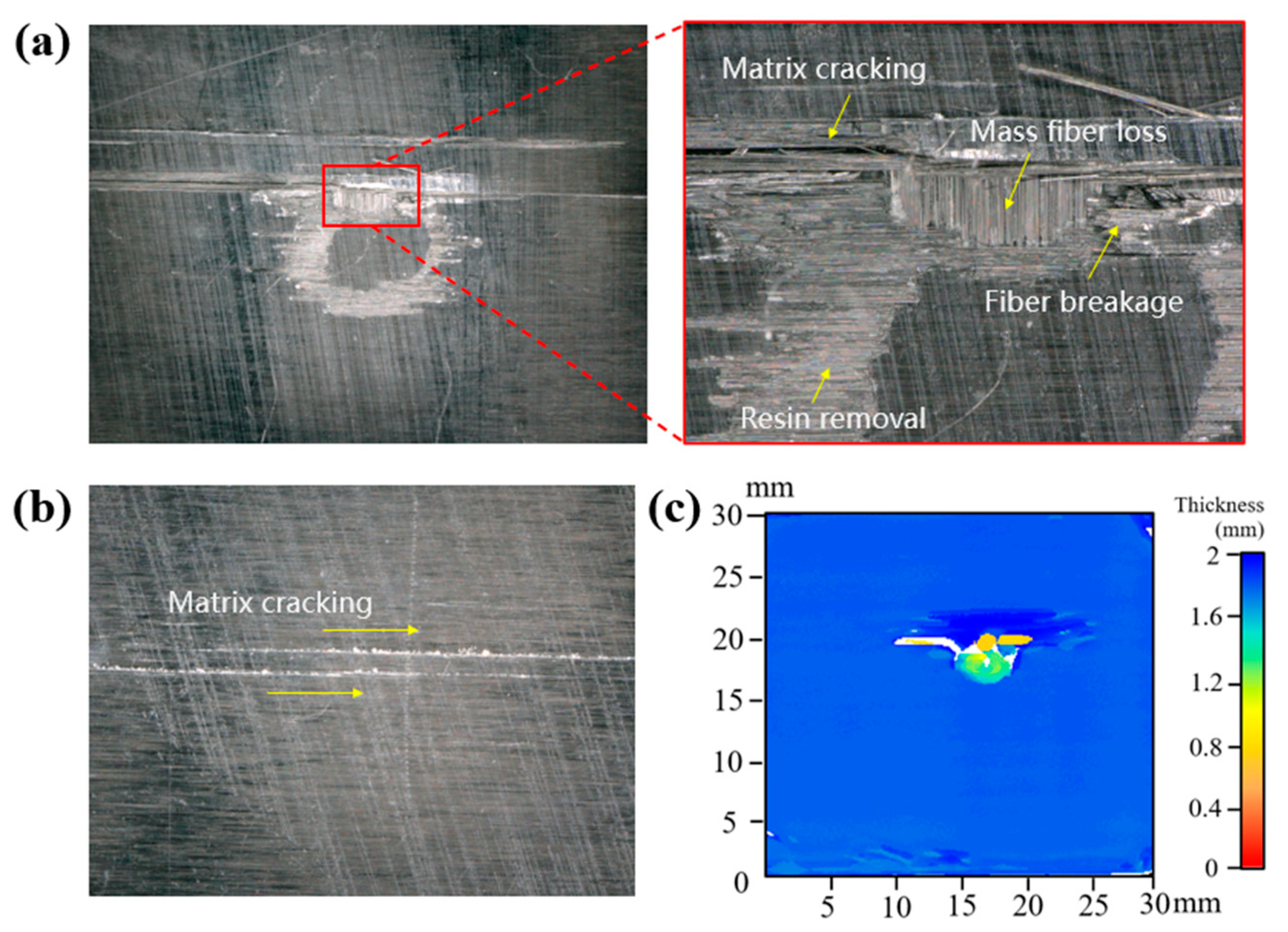
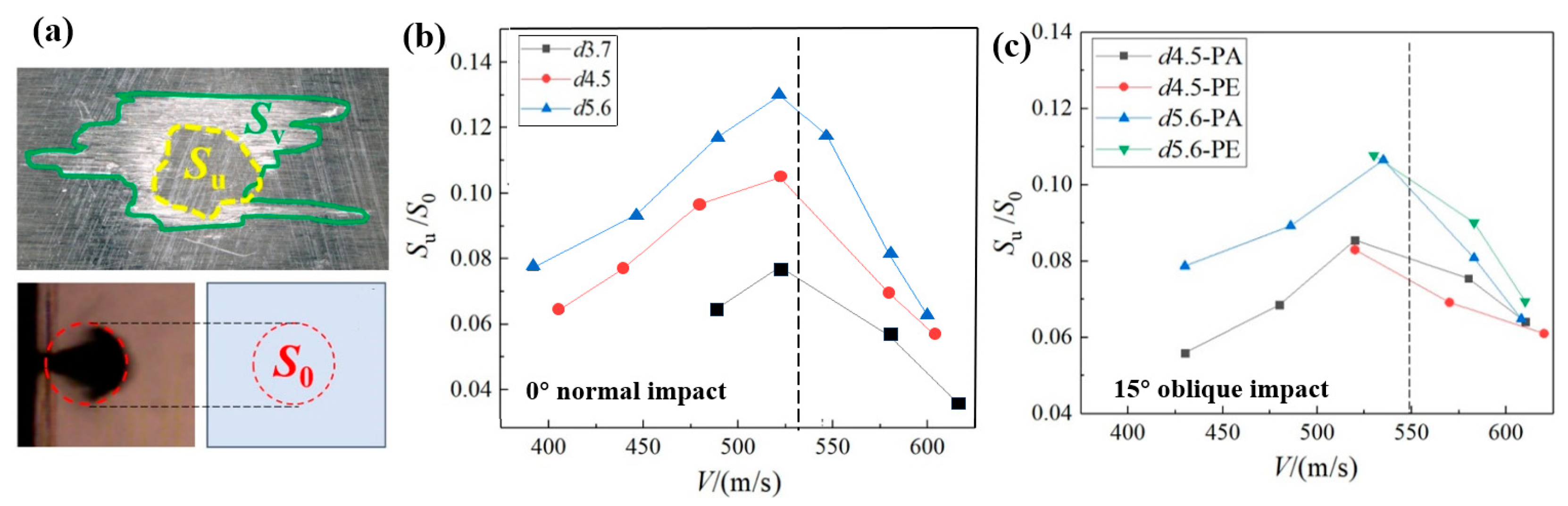
3.1. Typical Damage Characterization
3.2. Oblique Impact Results
3.2.1. Effect of the Impingement Angle
3.2.2. Effect of Fiber Orientation
3.3. Discussion on the Damage Mechanism
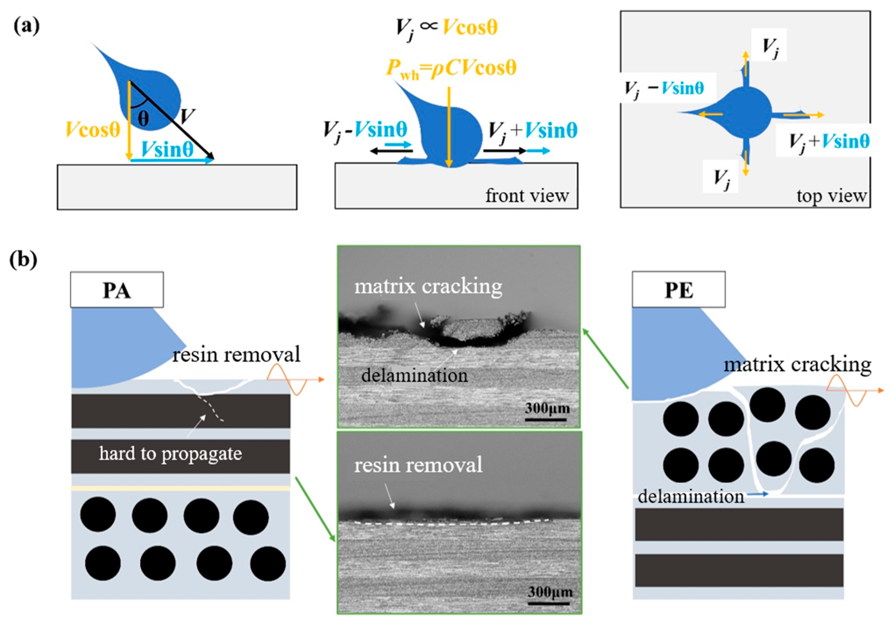
- An oblique impact at a small angle of 15° can lead to larger damage extents than a normal impact at 0° on CFRP laminates; a similar tendency was found in [16]. In an oblique impact, the velocity can be decomposed into a component perpendicular to the impact surface (Vcos θ) and a component parallel to the impact surface (Vsin θ). As shown in Figure 12, the vertical component Vcos θ dominates the magnitude of the water-hammer pressure, and the lateral jet velocity for a normal impact, Vj, can be considered proportional to Vcos θ, according to a previous investigation [12]. This can be written as Vj = aVcos θ (where a denotes the proportional factor, which has been found to be 5~10 in previous studies [12,13]). Meanwhile, the lateral jet is enhanced along the projected impact direction, such that the jetting velocity can be regarded as Vj + Vsin θ, derived as V(acos θ + sin θ). The shear force can be assumed to exhibit a positive correlation with the lateral jetting velocity. Notably, the jet velocity for an oblique impact along the projected direction may exceed that of the 0° normal impact (specifically, V(acos θ + sin θ) > aV), generating greater shear forces and damage dimensions. When the value of a varies from 5 to 10, the critical oblique angle θ is 11~22°, which matches the observed phenomenon for the 15° oblique impact in the present study.
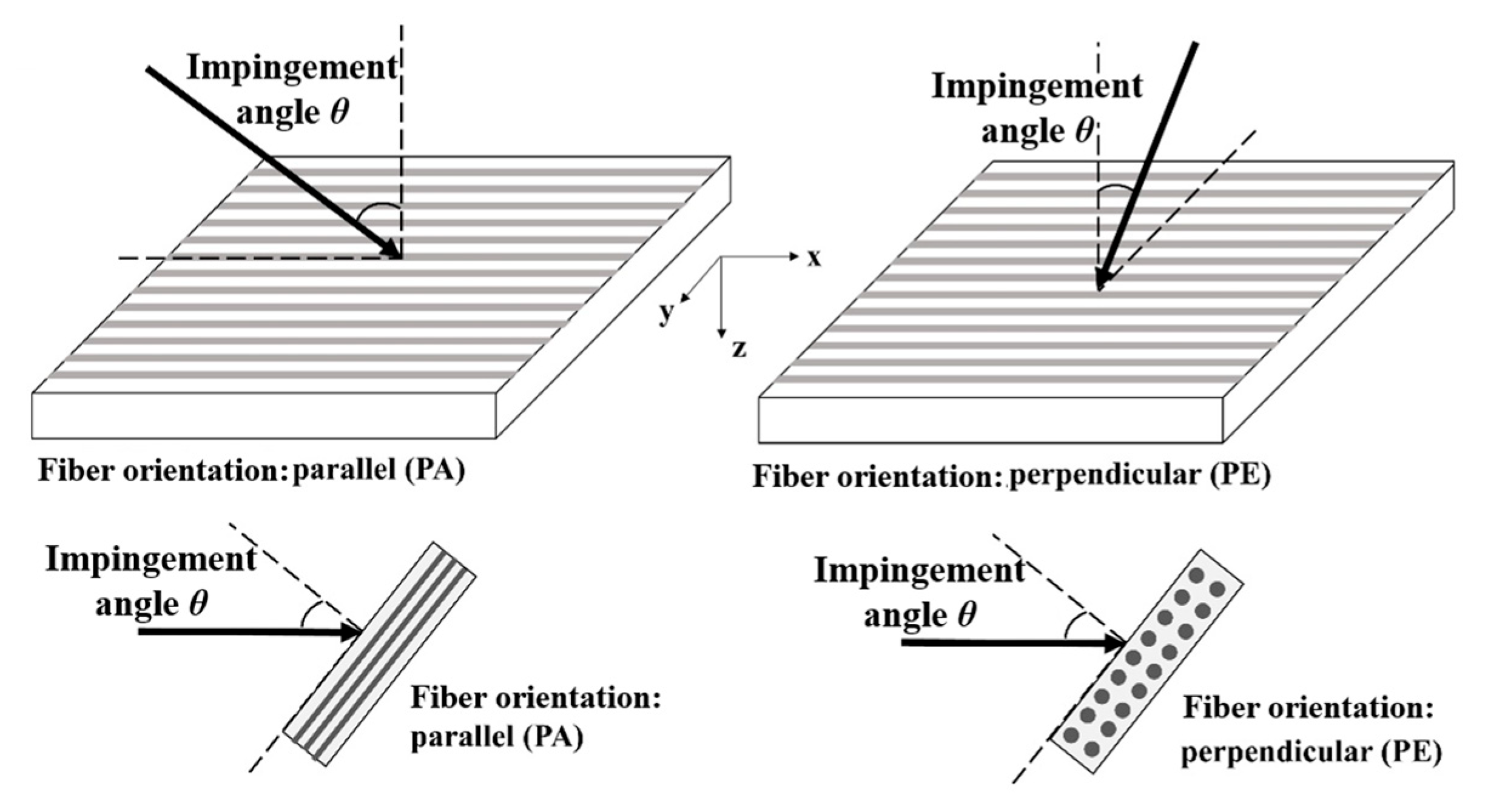
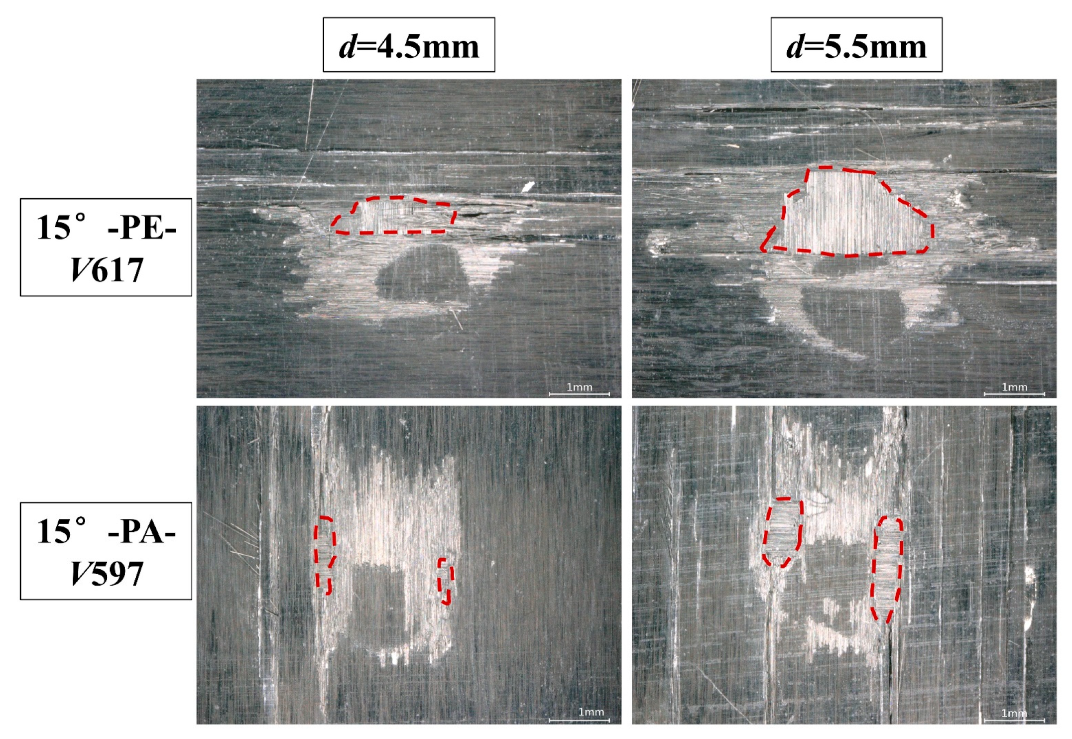
- The PA fiber orientation is more prone to cause resin removal than PE, which results in a lower single-jet impact damage threshold velocity (SST) for PA than PE at the same impact angle. The damage difference caused by the fiber orientation is determined by the inherent anisotropy of the laminate. Since the reinforcing phase used in this study consists of unidirectional continuous fibers, the matrix–fiber interface in the PA direction is also continuous. When the lateral jet is spread along a PA fiber orientation, matrix microcracks are more likely to initiate and expand along the interface, leading to erosion and removal of the resin damage. Conversely, an impact along the PE direction can only influence the regions between fibers in the matrix, and the interface is discontinuous and not conducive to the expansion of matrix microcracks. Therefore, the PA fiber orientation is more likely to cause initial resin removal damage than PE, resulting in a lower damage threshold velocity for a single-waterjet impact. The damage mechanism of resin removal is also associated with the effect of surface roughness, which is further explained in [21] in terms of the relationship between resin removal and the fiber orientation.
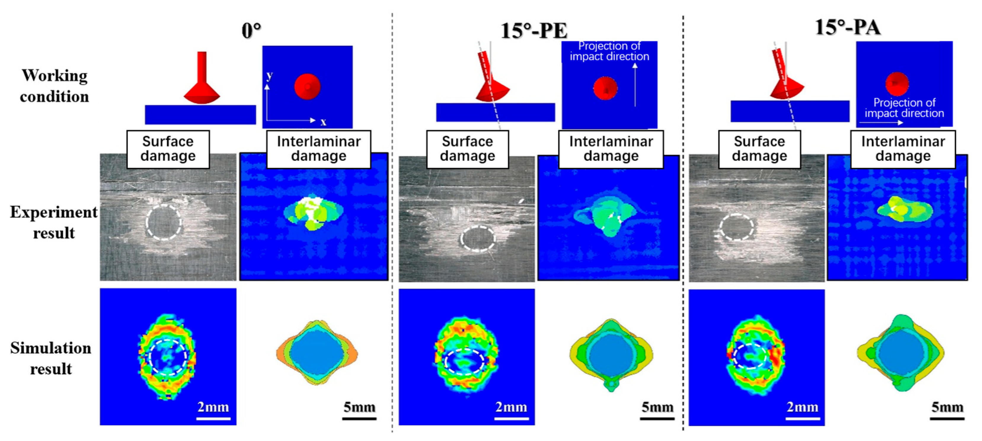
- A PE fiber orientation can lead to mass material peeling in comparison with PA, and the damage range is even much larger than from a normal impact. Due to the low transverse tensile strength of the laminate, the release tensile wave of the water-hammer pressure will generate matrix tensile cracks in this region and extend to the first interlaminar interface, which has been recounted in [6,22]. For the oblique impact shown in Figure 12, the velocity of the lateral jet as well as the induced shear force will be increased along the impact direction and cause delamination damage on the transverse region of the failure ring. The delamination region between layers overlaps with the matrix cracking and fiber breakage region within the surface failure ring, resulting in a larger area of material peeling than from the 0° normal impact. Conversely, if the same impact energy is exerted on CFRP laminates for a PA-orientation impact, the good longitudinal tensile performance of the laminate will inhibit the expansion of surface matrix cracks and thus block the intersection of interlaminar delamination and surface cracks, leading to minor material peeling along the impact direction.
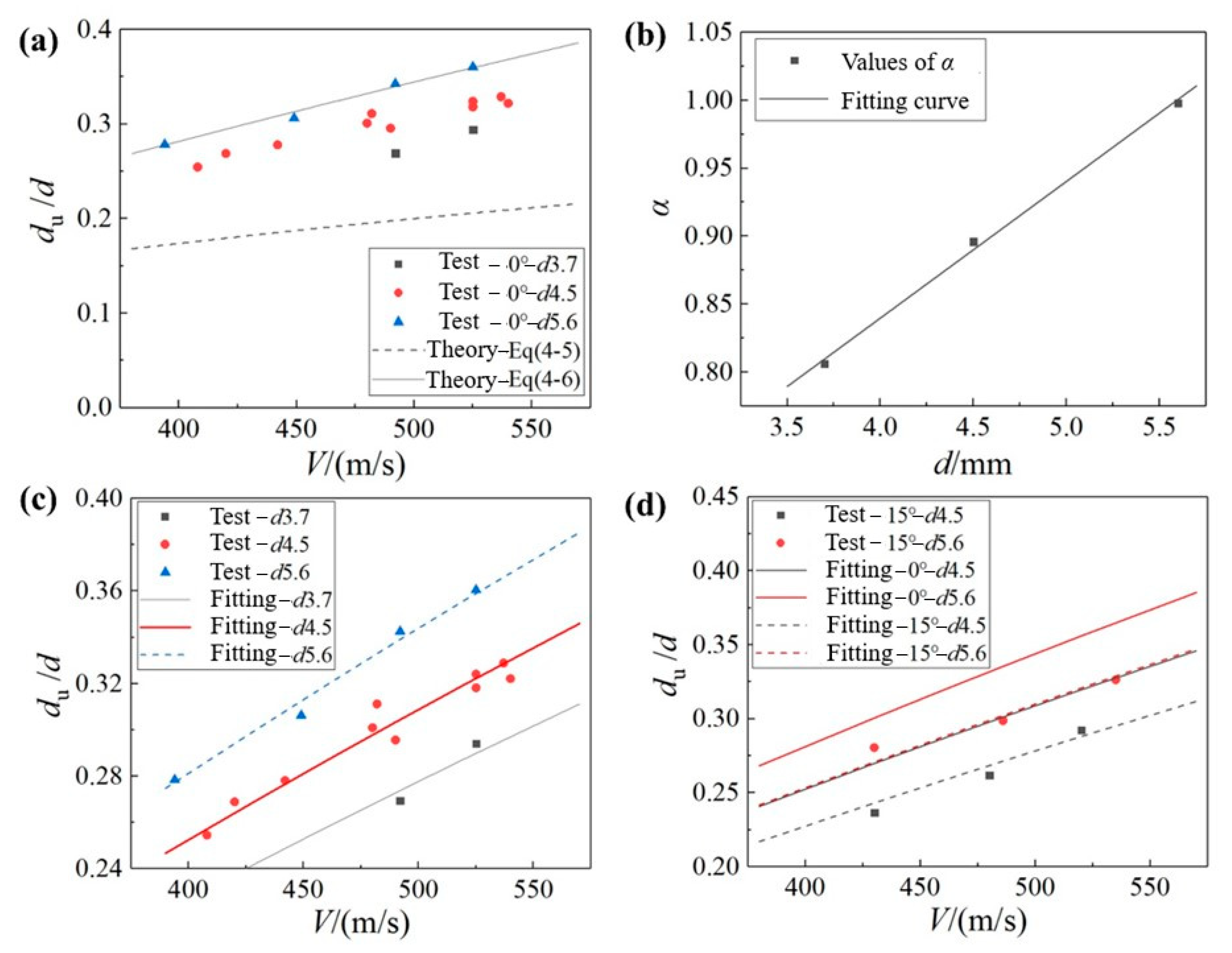
3.4. Fitting Model of the Undamaged Central Area
4. Conclusions
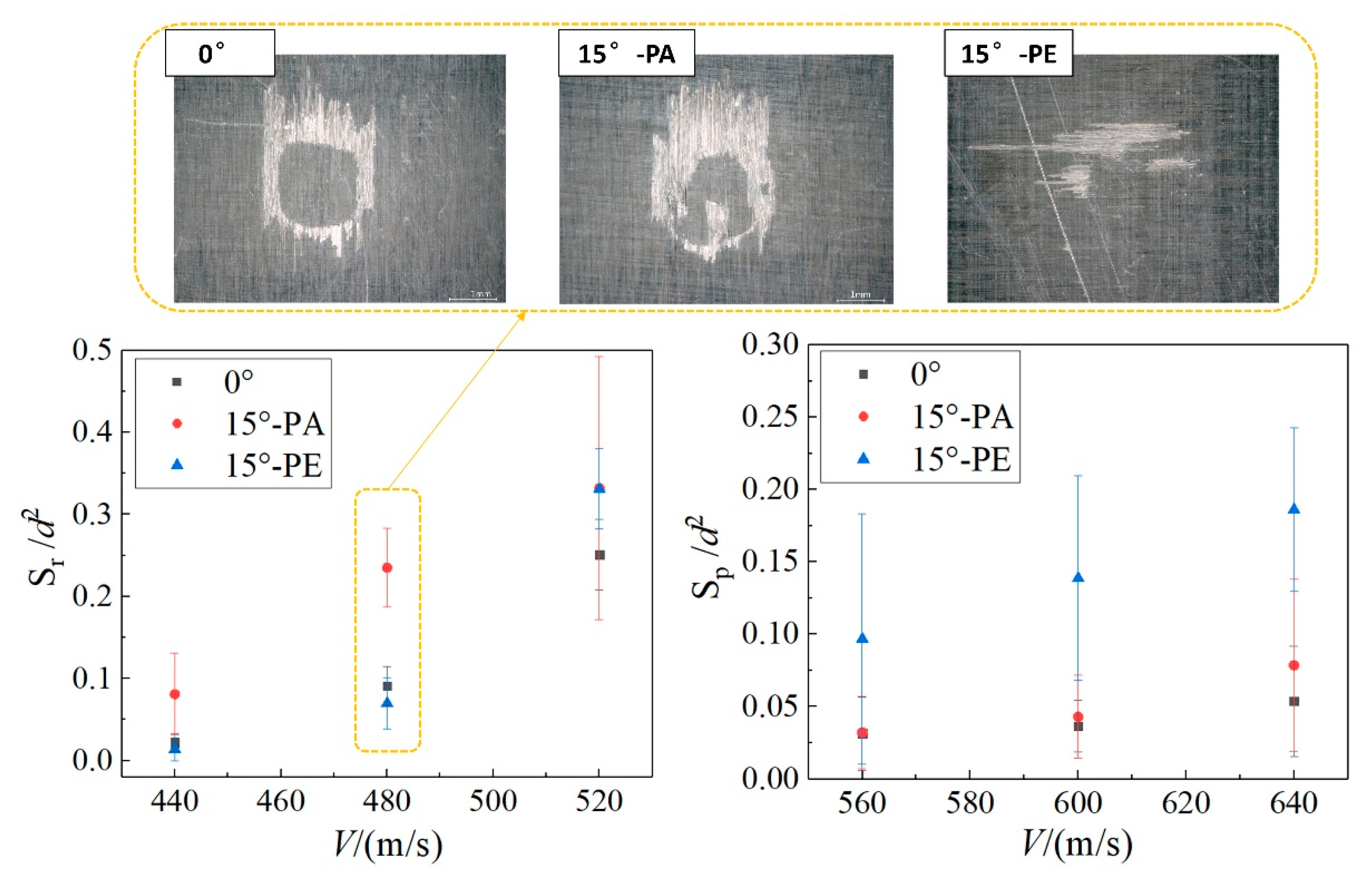
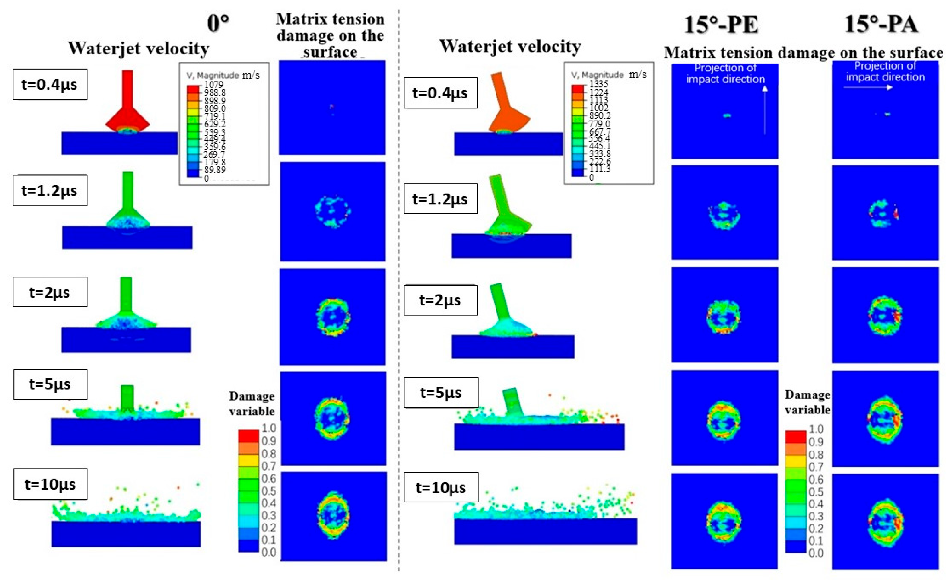
- The threshold velocity for single-jet-induced damage generally increases with the impact angle, while the damage severity decreases accordingly. However, a 15° oblique impact under high-velocity conditions may generate more extensive surface damage than a 0° normal impact. Finite-element modeling, validated by experimental data, suggests that this anomalous phenomenon stems from the increased lateral jet-particle velocity and resultant shear stress along the impact projection direction.
- PA fiber orientations in the CFRP laminates exhibited lower threshold velocities and incubation periods compared with their PE counterparts at identical angles, whereas a PE orientation demonstrated greater susceptibility to large-area material delamination (particularly under a 15° high-velocity impact). This divergent behavior originates from differential matrix microcrack initiation and propagation along fiber–matrix interfaces, with PE interfaces showing reduced resistance to resin removal. The damage extent under an oblique impact in the PE orientation even exceeded that of normal impact scenarios.
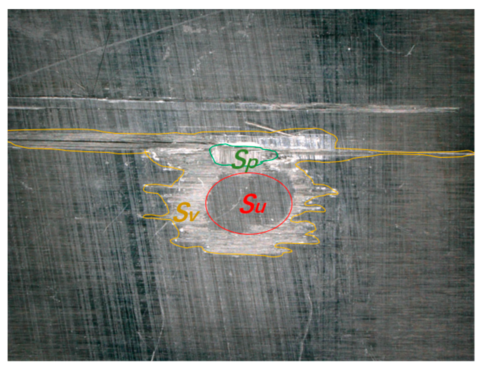
- Based on the theoretical formula for the water-hammer-pressure contact radius, the fitting model of the undamaged central area on the surface Su after single-waterjet impact is established, which generally realizes the decoupling and quantitative description of the influences of jet velocity, jet diameter, and impact angle. This model demonstrates good predictive capability for matrix-dominated surface failure patterns, achieving maximum prediction errors of below 20% for the parameter of the undamaged surface center area across validation cases.
- This study only analyzes the waterjet impact characteristics of unidirectional laminate composites without validating the universal applicability across other types of composites. Future research could focus on a broader spectrum of composites (including varying weaving patterns and matrix types), which would help to reveal the influence of material parameters on the waterjet impact resistance of composites.
Author Contributions
Funding
Institutional Review Board Statement
Informed Consent Statement
Data Availability Statement
Conflicts of Interest
Appendix A. Finite-Element Modeling

References
- Du, S.; Cui, Y.; Liu, R.; Xue, W.; Wang, F.; Liu, L. Effect of liquid droplet impingement on electrochemical passivation behavior of 321 stainless steel in 0.5 wt% NaCl solution. J. Mater. Res. Technol. 2024, 33, 7795–7807. [Google Scholar] [CrossRef]
- Fujisawa, N.; Yamagata, T.; Wada, K. Attenuation of wall-thinning rate in deep erosion by liquid droplet impingement. Ann. Nucl. Energy 2016, 88, 151–157. [Google Scholar] [CrossRef]
- Di, J.; Wang, S.; Yan, X.; Jiang, X.; Lian, J.; Zhang, Z.; Xie, Y. Experimental research on water droplet erosion resistance characteristics of turbine blade substrate and strengthened layers materials. Materials 2020, 13, 4286. [Google Scholar] [CrossRef] [PubMed]
- Li, F.; Wang, S.; Di, J.; Feng, Z. Effect of initial surface roughness on water erosion resistance of last stage blade substrate of steam turbine. Proc. ASME Turbomach. Tech. Conf. Expo 2020, 2B, 16262. [Google Scholar]
- Sha, M.; Sun, Y.; Li, Y.; Liu, Y.; Fedotenkov, G.; Rabinskiy, L.; Babaytsev, A.; Li, Y. Impact damage testing based on high-speed continuous water jet aircraft coatings. Chin. J. Aeronaut. 2024, 37, 249–264. [Google Scholar] [CrossRef]
- Hou, N.; Zhao, R.; Yue, Y.; Wang, X.; Cui, H.; Li, Y. Damage evolution of CFRP laminates by normal and oblique impact erosion of pulsating water jets. Compos. Struct. 2024, 338, 118079. [Google Scholar] [CrossRef]
- Kaore, A.N.; Kale, U.; Yerramalli, C.; Raval, H. Turbine specific fatigue life prediction model for wind turbine blade coatings subjected to rain erosion. Mater. Today Commun. 2022, 31, 103487. [Google Scholar] [CrossRef]
- Singh, A.; Singh, G.; Kumar, S. Comparative analysis on erosion performance of thin coated GFRP laminates in offshore conditions. Pigment. Resin. Technol. 2024. ahead of print. [Google Scholar] [CrossRef]
- Ibrahim, M.E.; Medraj, M. Water droplet erosion of wind turbine blades: Mechanics, testing, modeling and future perspectives. Materials 2019, 13, 157. [Google Scholar] [CrossRef] [PubMed]
- Gohardani, O. Impact of erosion testing aspects on current and future flight conditions. Prog. Aerosp. Sci. 2011, 47, 280–303. [Google Scholar] [CrossRef]
- Dashtkar, A.; Hadavinia, H.; Sahinkaya, M.N.; A Williams, N.; Vahid, S.; Ismail, F.; Turner, M. Rain erosion-resistant coatings for wind turbine blades: A review. Polym. Polym. Compos. 2019, 27, 443–475. [Google Scholar] [CrossRef]
- Ahmad, M. An overview of droplet impact erosion, related theory and protection measures in steam turbines. In Cavitation-Selected Issues, 1st ed.; Smith, J., Ed.; IntechOpen: London, UK, 2018; pp. 91–108. [Google Scholar]
- Hand, R.J.; Field, J.E.; Townsend, D. The use of liquid jets to simulate angled drop impact. J. Appl. Phys. 1991, 70, 7111–7118. [Google Scholar] [CrossRef]
- Hattori, S.; Kakuichi, M. Effect of impact angle on liquid droplet impingement erosion. Wear 2013, 298–299, 1–7. [Google Scholar] [CrossRef]
- Gorham, D.A.; Field, J.E. Anomalous behavior of high-velocity oblique liquid impact. Wear 1977, 41, 213–222. [Google Scholar] [CrossRef]
- Matthewson, M.J.; Gorham, D.A. An investigation of the liquid impact properties of a GFRP radome material. J. Mater. Sci. 1981, 16, 1616–1626. [Google Scholar] [CrossRef]
- Singh, A.; Singh, G.; Kumar, S.; Sehgal, S.S. Tribo-erosion performance of GFRP composite panels in both offshore and onshore environmental conditions. J. Offshore Mech. Arct. Eng. 2022, 144, 042003. [Google Scholar] [CrossRef]
- Barkoula, N.M.; Karger-Kocsis, J. Effects of fibre content and relative fibre-orientation on the solid particle erosion of GF/PP composites. Wear 2002, 252, 80–87. [Google Scholar] [CrossRef]
- Tewari, U.S.; Harsha, A.P.; Häger, A.M.; Friedrich, K. Solid particle erosion of carbon fibre– and glass fibre–epoxy composites. Compos. Sci. Technol. 2003, 63, 549–557. [Google Scholar] [CrossRef]
- Hou, N.; Zhao, R.; Li, J.; Wang, X.; Li, X.; Cui, H.; Li, Y. Impact damage of composite laminates with high-speed waterjet. Int. J. Impact Eng. 2022, 167, 104276. [Google Scholar] [CrossRef]
- Zhao, R.; Hou, N.; Wang, X.; Yue, Y.; Wang, B.; Li, Y.; Zhang, C. Mechanical response and damage mechanism of C/SiC composites impacted by high-velocity water jet. J. Eur. Ceram. Soc. 2023, 43, 3158–3171. [Google Scholar] [CrossRef]
- Hou, N.; Zhao, R.; Wang, X.; Tang, Z.; Cui, H.; Li, Y. Effects of surface topography and specimen thickness on high-speed raindrop impact damage of CFRP laminates. Chin. J. Aeronaut. 2023, 36, 186–200. [Google Scholar] [CrossRef]
- Lesser, M.B. Analytic solutions of liquid-drop impact problems. Proc. R. Soc. Lond. A Math. Phys. Eng. Sci. 1981, 377, 289–308. [Google Scholar]
- Engel, O.G. Damage produced by high-speed liquid drop impacts. J. Appl. Phys. 1973, 44, 692–704. [Google Scholar] [CrossRef]
- Zhao, J.; Chen, K.; Liu, R.; Liang, M. Modeling study of liquid impingement erosion of NiAl alloy. Wear 2014, 311, 65–70. [Google Scholar] [CrossRef]
- Wang, L.L.; Field, J.E.; Sun, Q.; Liu, J. Surface damage of polymethylmethacrylate plates by ice and nylon ball impacts. J. Appl. Phys. 1995, 78, 1643–1649. [Google Scholar] [CrossRef]
- Golub, G.H.; Vanloan, C.F. An Analysis of The Total Least-Squares Problem. Siam J. Numer. Anal. 1980, 17, 883–893. [Google Scholar] [CrossRef]
- Li, X.; Ma, D.; Liu, H.; Tan, W.; Gong, X.; Zhang, C.; Li, Y. Assessment of failure criteria and damage evolution methods for composite laminates under low-velocity impact. Compos. Struct. 2019, 207, 727–739. [Google Scholar] [CrossRef]
- Camanho, P.P.; Davila, C.G.; de Moura, M.F. Numerical Simulation of Mixed-Mode Progressive Delamination in Composite Materials. J. Compos. Mater. 2016, 37, 1415–1438. [Google Scholar] [CrossRef]
- Hsu, C.Y.; Liang, C.C.; Teng, T.L.; Nguyen, A.T. A numerical study on high-speed water jet impact. Ocean. Eng. 2013, 72, 98–106. [Google Scholar] [CrossRef]
- Hamashima, H. Determination of JWL parameters for non-ideal explosive. In Proceedings of the 12th International Symposium on Detonation, San Diego, CA, USA, 11–16 August 2004; pp. 331–334. [Google Scholar]


| ρ/(kg/m3) | E11/GPa | E22/GPa | G12/GPa | V12 |
|---|---|---|---|---|
| 1578 | 115 | 9 | 3.3 | 0.33 |
| Xt/MPa | Xc/MPa | Yt/MPa | Yc/MPa | S12/MPa |
| 2300 | 1050 | 42 | 143 | 116 |
| Glass transition temperature (Tg) of the resin/°C | 110 | |||
| Working Condition | 0° | 15°-PE | 15°-PA |
|---|---|---|---|
| Maximum velocity of the lateral jetting Vj (occurrence time) | 1079 m/s (1.8 μs) | 1347 m/s (3.2 μs) | 1293 m/s (2.8 μs) |
| Maximum value of the stress component S33 (occurrence time) | 2.082 GPa (0.2 μs) | 1.865 GPa (0.4 μs) | 1.996 GPa (0.4 μs) |
| Maximum value of the stress component S23 (occurrence time) | 0.485 GPa (1 μs) | 0.501 GPa (1.2 μs) | 0.453 GPa (0.8 μs) |
| Maximum value of the stress component S13 (occurrence time) | 0.412 GPa (1 μs) | 0.457 GPa (0.8 μs) | 0.489 GPa (1.2 μs) |
| V (m/s) | d (mm) | θ (°) | Su (mm2) | ||
|---|---|---|---|---|---|
| Test Result | Prediction | Error | |||
| 428 | 5.9 | 0 | 2.42 | 2.62 | 8.47% |
| 471 | 6.1 | 0 | 3.33 | 3.46 | 4.10% |
| 507 | 6.3 | 0 | 3.84 | 4.37 | 13.7% |
| 514 | 5.9 | 0 | 3.29 | 3.64 | 10.5% |
| 450 | 6.3 | 15 | 2.49 | 2.87 | 15.4% |
| 535 | 6.1 | 15 | 3.21 | 3.52 | 9.80% |
| 492 | 6.3 | 30 | / | 1.75 | / |
| 600 | 5.9 | 30 | 1.89 | 2.00 | 5.99% |
| 557 | 6.1 | 45 | / | 0.58 | / |
| 610 | 5.9 | 45 | / | 0.61 | / |
| Average error | 9.71% | ||||
| Maximum error | 15.4% | ||||
Disclaimer/Publisher’s Note: The statements, opinions and data contained in all publications are solely those of the individual author(s) and contributor(s) and not of MDPI and/or the editor(s). MDPI and/or the editor(s) disclaim responsibility for any injury to people or property resulting from any ideas, methods, instructions or products referred to in the content. |
© 2025 by the authors. Licensee MDPI, Basel, Switzerland. This article is an open access article distributed under the terms and conditions of the Creative Commons Attribution (CC BY) license (https://creativecommons.org/licenses/by/4.0/).
Share and Cite
Hou, N.; Li, Y.; Liu, P. Damage Mechanism and Modeling of CFRP Laminates Impacted by Single Waterjets: Effect of the Impact Direction. Materials 2025, 18, 3495. https://doi.org/10.3390/ma18153495
Hou N, Li Y, Liu P. Damage Mechanism and Modeling of CFRP Laminates Impacted by Single Waterjets: Effect of the Impact Direction. Materials. 2025; 18(15):3495. https://doi.org/10.3390/ma18153495
Chicago/Turabian StyleHou, Naidan, Yulong Li, and Ping Liu. 2025. "Damage Mechanism and Modeling of CFRP Laminates Impacted by Single Waterjets: Effect of the Impact Direction" Materials 18, no. 15: 3495. https://doi.org/10.3390/ma18153495
APA StyleHou, N., Li, Y., & Liu, P. (2025). Damage Mechanism and Modeling of CFRP Laminates Impacted by Single Waterjets: Effect of the Impact Direction. Materials, 18(15), 3495. https://doi.org/10.3390/ma18153495