1. Introduction
The performance of an aircraft engine turbine improves by increasing the temperature of the gases introduced into the turbine [
1]. Increasing the gas temperature from 900 to 1250 °C causes a 30% increase in the output power [
2]. The most critical elements of an aircraft engine turbine are turbine blades. They are subject to strong mechanical stresses and work in a highly corrosive environment [
3,
4,
5]. Therefore, a turbine blade must exhibit the following properties: (1) resistance to thermal fatigue, creep, and mechanical fatigue; (2) resistance to hot corrosion and oxidation; (3) high microstructural stability; and (4) resistance to erosion. Ni-based superalloys have a high melting temperature, creep and fatigue resistance, therefore, hot part elements in gas turbines are made from them [
6,
7,
8,
9,
10]. The necessity of protection of the hot part elements from high working temperatures and oxidation requires the use of special coating systems on their surface [
11]. Thermal barrier coatings (TBCs) are multilayer coating systems consisting of an intermediate layer (
bond coat) and a ceramic top layer (
top coat) designed to protect the elements from oxidation and high working temperatures, respectively [
12,
13,
14,
15]. The ceramic top layer is ca. 100–400 µm thick and consists of yttrium oxide partially stabilized by zirconium oxide. Two groups of bond coatings are generally used [
12,
13,
14,
15]. The first group is overlay coatings with a typical MCrAlX composition, where M denotes Ni, Co, or Fe and X means oxygen-reactive elements, namely Zr, Si, Hf, and Y [
16,
17,
18]. The composition of the coating is selected in such a way that the microstructure consists of a β phase in a γ matrix. Overlay coatings are deposited by thermal spray or physical vapor deposition. The adhesion of overlay coatings to the substrate produced by thermal spray or physical vapor deposition methods is limited. The aspect of adhesion is fundamental: in rotating turbine blades running at thousands of revolutions per minute, a lack of a coating will cause destruction of the engine. The second group is diffusion aluminide coatings [
19,
20,
21,
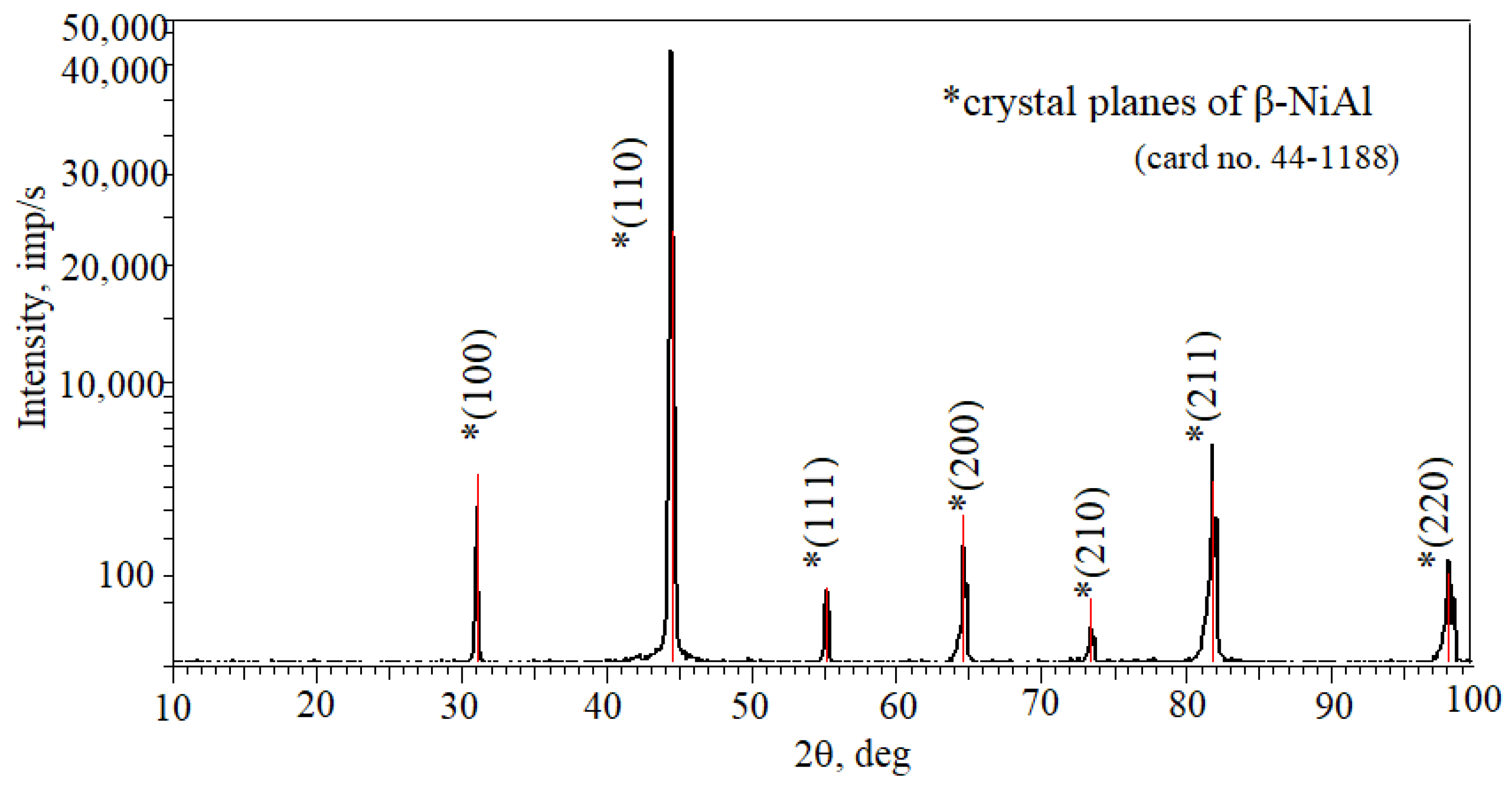
22]. The β-NiAl phase is the main phase of these coatings. Low density, high melting temperature, high elasticity modulus, and good adherence to the substrate are the distinctive features of the β-NiAl phase. These properties make the β-NiAl phase very beneficial for use in coatings. The efficiency of aluminide coatings is related to the presence of the intermetallic aluminum-rich matrix layer, which is an aluminum reservoir to form an α-Al
2O
3 protective scale. The strongly compact structure of the scale phase ensures a drastic reduction of the inward diffusion of oxygen ions and hence improves the oxidation performance of nickel-based superalloys above 1000 °C.
Aluminide coatings have often been deposited by means of the pack cementation method [
23,
24,
25]. The formation of a β-NiAl coating is a result of the reaction between the mixed powder and coated elements. The formation of coatings by pack cementation has been investigated widely [
23,
24,
25]. It was found that the composition and structure of coatings depend on the kind of the substrate [
23,
24,
25]. This means that coatings are usually tailor-made for a specific alloy. Low cost and good coating reproducibility are the main advantages of the pack cementation method. However, particles used in this method may be entrapped in the outer part of the coating. Hence, the continuity of the coating is hindered.
Out-of-the pack aluminizing is an alternative method, in which coated components are situated above the powder mixture containing aluminum [
26]. Coatings produced by the out-of-the pack aluminizing method are much cleaner and more homogeneous than those produced by pack aluminizing.
Slurry aluminizing is an alternative method used to produce oxidation-resistant coatings [
27]. The slurry is a suspension created by mixing a binder with the aluminum powder. The suspension is sprayed on the superalloy substrate, dried, and then heat-treated to obtain a diffused coating. However, the heat treatment of slurry coatings leads to the formation of volatile organic compounds that contain phosphorus and chromium derivatives. Therefore, the use of slurry coatings is limited.
Vapor-phase aluminizing is a successive technological method used to produce oxidation-resistant coatings [
28,
29,
30]. Aluminum pellets are used in this process. Simplification of the discharge and charge processes of the aluminum source is an advantage, since no volatile dust is created. Vapor-phase aluminizing becomes the preferred aluminizing method due to the excellent process control, the cleanliness of the process, the fact that there is no need for high vacuum, no reactions during the heating and cooling periods, and the homogeneity of the produced coating. Coatings on a nickel superalloy substrate obtained in the abovementioned process are used in F100 military engines, which power the F-16 and F-15 fighter aircrafts.
Vapor-phase aluminizing can usually be performed in three different ways: low-temperature high-activity—performed below 950 °C (LTHA), high-temperature high-activity (HTHA), and high-temperature low-activity—performed above 1000 °C (HTLA) [
28,
29,
30]. The diffusion rate of aluminum is lower than that of nickel in HTLA aluminizing. Therefore, the nickel aluminide coating grows outwardly, and the β-NiAl phase is the main phase of the coating. The diffusion rate of aluminum is greater than that of nickel in LTHA aluminizing. Therefore, the nickel aluminide coating grows inwardly, and the Al-rich δ-Ni
2Al
3 is the main phase of the coating. The nickel diffusion rate is higher than that in LTHA aluminizing and is comparable with the aluminum diffusion rate in HTHA aluminizing. Furthermore, the initial growth of HTHA coatings is controlled by aluminum’s inward diffusion and then by nickel’s outward diffusion. As a result, the aluminide coating consists of only the β-NiAl phase or both the β-NiAl and δ-Ni
2Al
3 phases. The presence of the δ-Ni
2Al
3 phase is not preferred because of its brittleness and instability at temperatures higher than 1133 °C. The undesired δ-Ni
2Al
3 phase is changed into the desired β-NiAl phase by an additional heat treatment process, which is carried out at ca. 1100 °C for a few hours [
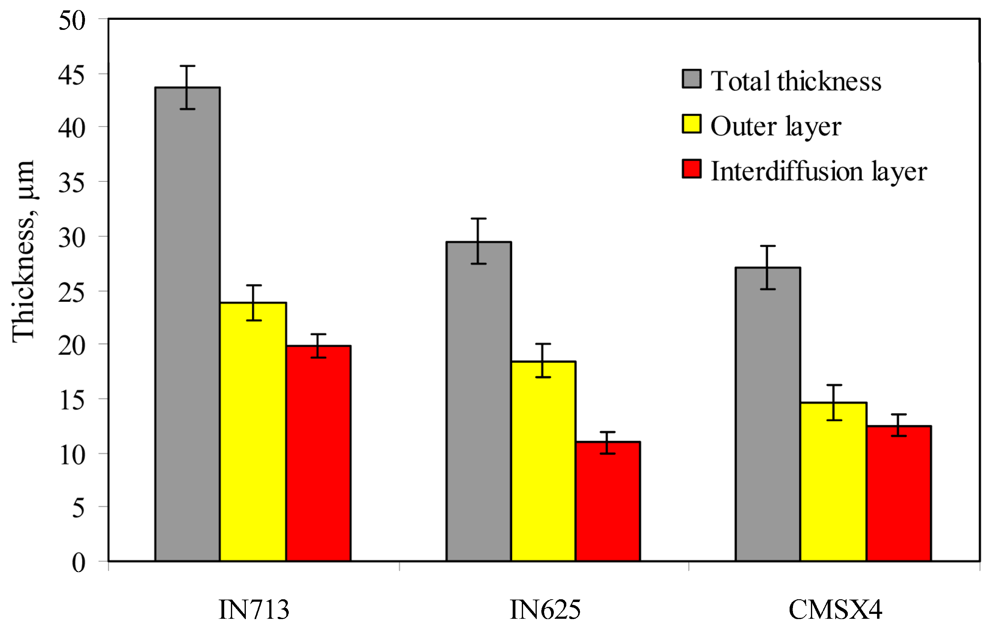
31]. The aluminized coating’s microstructure consists of two layers: the interdiffusion layer and the additive layer. The interdiffusion layer forms between the additive layer and the substrate due to the compositional change between them and consists of a matrix phase with different types of precipitates depending on the kind of the substrate.
Mo et al. [
32] produced aluminide coatings on a K444 nickel-based superalloy at 850, 900, 950, 1000, and 1050 °C for 1.5 h by means of the vapor-phase aluminizing method. A bilayer structure was observed. The outer zone of the coating was the β-NiAl phase, while the interdiffusion zone was mostly comprised of nickel–aluminum intermetallics, topologically close-packed phases, and carbides. Christoglou et al. [
33] produced aluminide coatings on ARMCO iron at 1000 °C for 4 h by means of the fluidized bed chemical vapor deposition (FB-CVD) method. A double-layer structure was observed. The outer zone of the coating was the FeAl phase, while the interdiffusion zone was composed of a solid solution of aluminum in α-Fe. Wang et al. [
34] deposited aluminide coatings on Haynes 188 and WI-52 cobalt-based superalloys at 1080 °C for 4 h by means of vapor-phase aluminizing with the use of 15Al–85Cr and 44Al–56Cr nuggets. Aluminide coatings deposited on Haynes 188 with 15Al–85Cr and 44Al–56Cr nuggets consisted of a β-(Co,Ni)Al phase outer layer and a Cr-rich + W-rich precipitated phase interdiffusion layer; on the other hand, aluminide coatings deposited on WI-52 with 15Al–85Cr nuggets consisted of a CoAl phase outer layer and a Cr-rich + W-rich precipitated phase interdiffusion layer.
The coatings used within the turbine differ according to the considered rotor stage. Blades of the first stage are coated with a platinum-modified aluminide, while turbine blades of the third stage are coated with an unmodified aluminide because of the low temperatures in which they work.
World manufacturers of aircraft engines—Pratt and Whitney, Rolls-Royce, or General Electric—look for an aluminizing process which is environmentally friendly, repeatable, and ensures the production of aluminide coatings with uniform thickness on both the external and internal surfaces of cooling channels of turbine blades.
It was found that the compositional difference between the substrate and the coatings ensures the driving force for the various elements’ interdiffusion when the coated superalloy is subjected to high temperature [
7,
10,
11]. One of the main elements of the aluminide coating and the substrate is aluminum. The loss of aluminum from the aluminide coating toward the surface is well-understood. However, the loss of aluminum from the aluminide coating toward the substrate is not explained. A large aluminum concentration lowers the melting point of superalloys. Chromium is a constituent of superalloys. It improves the oxidation resistance of superalloys to 816 °C, decreases the aluminum requirement for alumina scale formation, and lowers creep strength. Nickel diffuses outwardly to form NiAl for a NiCr alloy with 10 wt.% chromium during low-activity aluminizing. The alloy loses nickel near the interface. On the other hand, the alloy becomes enriched with chromium near the interface. The chromium level is within the limit of solubility, and no chromium particles occur. A chromium-saturated NiAl phase forms during the low-activity aluminizing of a Ni10Cr alloy. Nickel diffuses outwardly to form NiAl for a NiCr alloy with 20 wt.% chromium during low-activity aluminizing. The alloy loses nickel and increases the chromium concentration. An increase in the chromium concentration at the near-interface region exceeds the limit of solubility and leads to α-Cr precipitates near the interface in the alloy. Precipitation of α-Cr in the coating reduces ductility and oxidation resistance of coating. Refractory elements such as molybdenum, tungsten, or rhenium diffuse to the surface of the superalloy and form carbides MC, M
6C, M
23C
6 or intermetallic phases, which impede outward nickel diffusion from the substrate to the surface, thereby inhibiting the coating’s growth. The literature data indicate that the composition and structure of coatings depend on the substrate [
23,
24,
25]. In turn, the chemical and phase composition of coatings influences the lifetime of superalloys [
23,
24,
25]. This means that coatings are tailor-made for an individual alloy. There is a lack of information on how compositions of substrates affect the microstructure of aluminide coatings and their lifetime at high temperature. To fill these gaps, this study provides new insights regarding the analysis of the structure of aluminide coatings on the IN713, IN625, and CMSX4 Ni-based superalloys and their oxidation resistance at elevated temperatures. Superalloys were taken as the substrate since they are used in the hot parts of aircraft engines. Aluminide coatings were produced via a “clean” chemical vapor deposition process, which meets manufacturers’ environmental protection requirements, thus fulfils the Industry 4.0 requirements, where reduction of environmental impact is a key factor.
2. Materials and Methods
The IN713 (polycrystalline), IN625 (polycrystalline), and CMSX4 (monocrystalline) Ni-based superalloys were used as the substrate. The nominal compositions of the IN713, IN625, and CMSX4 superalloys are shown in
Table 1 [
6,
35,
36].
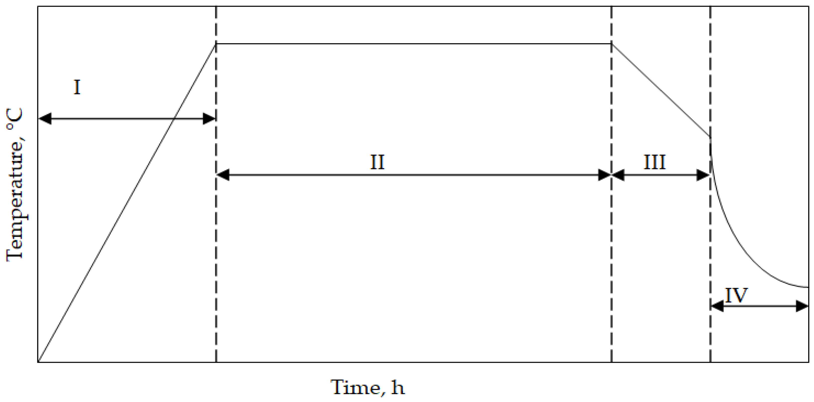
The cylinder-shaped superalloys with a diameter of 15 mm and a height of 4 mm were cut, ground up to SiC No1000, and degreased in ethanol. Finally, the samples were aluminized. High-temperature low-activity aluminizing (HTLA) was performed through a chemical vapor deposition process. AlCl3 halide (IonBond Company, Olten, Switzerland) was an aluminum source. Hydrogen as the carrier (IonBond Company, Olten, Switzerland) gas supplied the halide to the superalloy samples. The aluminizing process consisted of the following steps:
I—heating from room temperature to 1050 °C;
II—aluminizing at 1050 °C for 8 h;
III—cooling samples with a furnace to 500 °C;
IV—cooling samples in ambient air.
A temperature scheme during the chemical vapor deposition aluminizing process is shown in
Figure 1. The elaborated process is “clean” and meets manufacturers’ environmental protection requirements. Hence, it fulfils the Industry 4.0 requirements, where the reduction of environmental impact is a key factor.
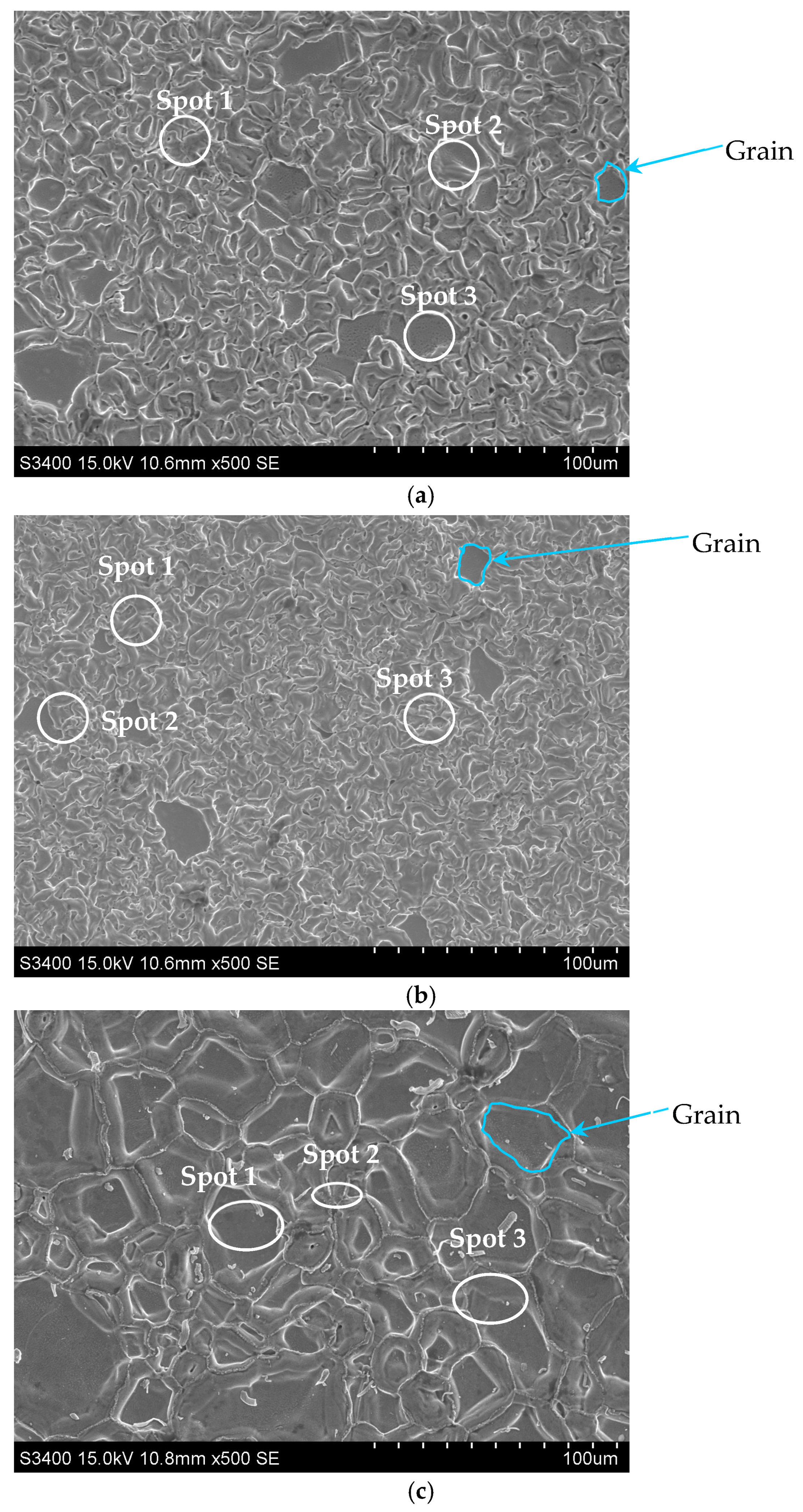
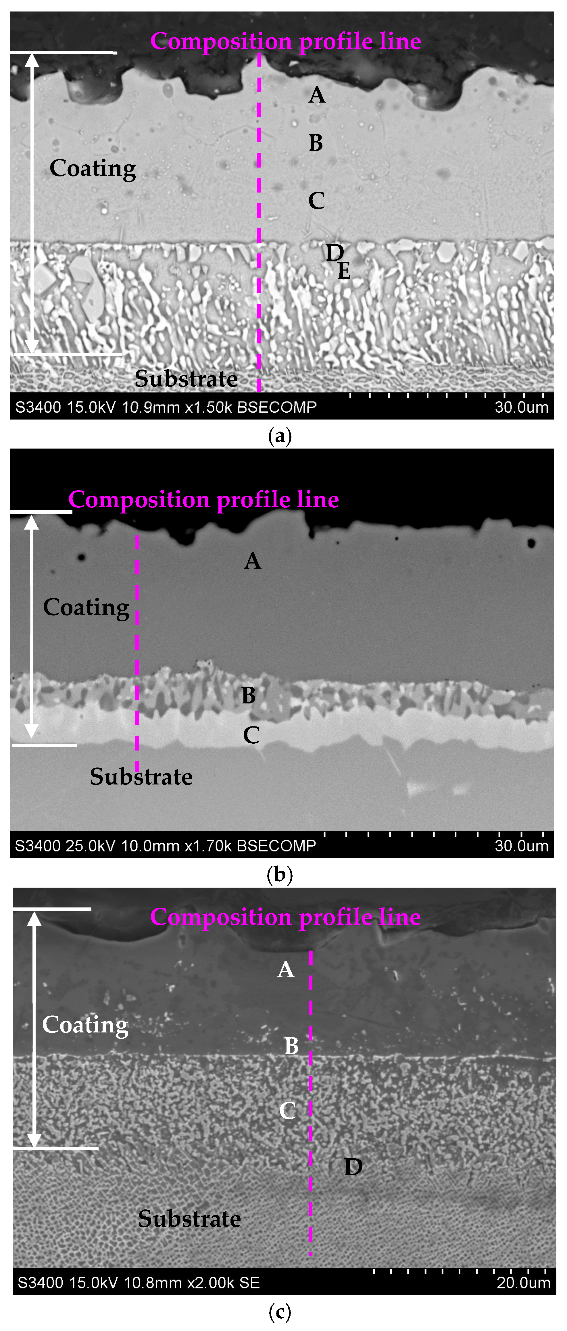
Aluminide coatings’ surfaces were investigated with a Hitachi S-3400N scanning electron microscope (SEM) (Hitachi America, Ltd., Iowa City, IA, USA) equipped with an energy dispersive spectroscope (EDS) (Hitachi America, Ltd., Iowa City, IA, USA). Then, coated samples were cut, mounted, gritted, and polished to get metallurgical samples. The thickness of the coatings was measured using a Nikon Epiphot 300 optical microscope (Nikon, Tokyo, Japan). A phase analysis of the coatings was performed by means of X-ray diffraction (XRD) (XTRa ARL, Waltham, MA, USA) using Cu-Kα radiation in the 10–100° interval. An oxidation test was carried out in a muffle furnace (Czylok, Jastrzębie-Zdrój, Poland) in the air at 1100 °C. The furnace was heated up to 1100 °C; then, the coated samples were placed there and held for 20 h. Then, the samples were taken out, air-cooled for 2 h to room temperature, and weighed with an accuracy of 0.0001 g. Uniform air flow was maintained. The above action was a cycle, while the total oxidation time was ca. 400 h. The oxidation time was that long to record the loss of lifetime of the samples.


