Article

Corrosion and Antifouling Behavior of a New Biocide-Free Antifouling Paint for Ship Hulls Under Both Artificially Simulated and Natural Marine Environment

by
Polyxeni Vourna
1,*,
Pinelopi P. Falara
2,
Evangelos V. Hristoforou
3 and
Nikolaos D. Papadopoulos
4
1
Institute of Nanoscience and Nanotechnology, National Centre for Scientific Research “Demokritos”, 15341 Agia Paraskevi, Greece
2
School of Chemical Engineering, National Technical University of Athens, 9 Iroon Polytechniou Str., 15780 Zografou, Greece
3
Institute of Communication and Computer Systems, 15773 Zografou, Greece
4
Department of Research and Development, BFP Advanced Technologies G.P., Peristeri Industrial Zone, 12133 Athens, Greece
*
Author to whom correspondence should be addressed.
Materials 2025, 18(13), 3095; https://doi.org/10.3390/ma18133095
Submission received: 21 May 2025 / Revised: 18 June 2025 / Accepted: 26 June 2025 / Published: 30 June 2025
(This article belongs to the Special Issue Corrosion Resistance and Protection of Metal Alloys)

Abstract

This study involved covering naval steel samples with a biocide-free, innovative antifouling coating, which were subsequently immersed in either artificial seawater or a Greek maritime environment for durations ranging from 1 to 50 weeks. The objective was to assess the efficacy of the coating as an anticorrosion and antifouling barrier on the steel samples. Non-coated samples were analyzed alongside the coated samples for comparative purposes. The findings indicate that a reduction in coating thickness during static immersion in laboratory settings leads to the removal of precipitated corrosion products, exposing a fresh layer of “pristine” coating. This layer decreases the corrosion rate by almost 90% throughout extended immersion durations. The efficacy of the coating is validated through trials conducted in natural maritime environments, demonstrating an operational performance of 99% for the coated samples after 50 weeks of continuous exposure to seawater. In fact, the coated samples showed only soft fouling, in contrast to the uncoated samples which were characterized by a strong presence of hard fouling within a short period of time after immersion.

1. Introduction

Marine biofouling denotes the undesirable colonization of solid artificial structures (e.g., ship hulls, mechanical equipment, or pier pylons) submerged in seawater by marine organisms, including biotic and abiotic dissolved compounds, microorganisms, plants, and animals [1,2,3].
Over 4000 recognized species of biofoulants exist in maritime environments [4]. Biofouling is a multifaceted process including the colonization of an immersed surface by microscopic organisms (microfouling) and bigger species (macrofouling). Microfouling mostly encompasses proteins, bacteria, fungi, viruses, cyanobacteria, protozoa, and microalgae [5]. Macrofoulants encompass macroalgae (multicellular creatures) and macroinvertebrates (calcareous hard fouling organisms: acorn barnacles, tubeworms, mussels bryozoans, sedentary polychaetes, bivalves, ascidians and soft-fouling organisms: hydroids, solidary anemones, sponges, tunicates) [6].
Two models have been presented to elucidate the process of biofouling evolution on submerged surfaces in marine environments: a classical model [6] and a dynamic model [6]. The traditional colonization model delineates the intricate life cycle of biofouling as a sequence of four primary stages in the colonization of marine organisms [7,8,9,10]. In the dynamic model of biofouling, the lack of one colonization stage does not inhibit the emergence of another stage, as colonization is significantly influenced by the variety and quantity of organisms [5,6]. Nonetheless, the requirement for the establishment of an initial colonization layer persists in the two proposed models for elucidating the biofouling process of surfaces submerged in seawater [5].
The biological deposition of fouling on ship hulls is a global issue [11], as it is associated with interconnected consequences:
  • Heightened hull corrosion rates result in augmented surface roughness [12], causing drag resistance to increase [13] by as much as 70% during the initial colonization phases [14] and up to 86% in subsequent stages [15];
  • Elevated friction resistance may lead to a decrease in cruising speed [16];
  • To sustain the preset speed, greater fuel consumption is necessitated [17], potentially reaching 40% [18];
  • Excessive fuel consumption results in economic and environmental repercussions: Escalation in transportation expenses [19] and greenhouse gas emissions that could threaten global warming [20];
  • The accumulation of marine organisms on the ship’s hull necessitates more frequent dry-docking [21], leading to heightened maintenance expenses [22] and diminished voyage duration [23];
  • The recurrent dry-docking procedure generates substantial toxic waste, detrimental to the environment [24];
  • Vessels transport invasive organisms globally, potentially resulting in the bio-invasion of non-native species in marine ecosystems devoid of natural enemies [25].
  • Τhe proliferation of contaminating organisms modifies the interface between the metal surface and its surroundings, resulting in the onset of microbially induced corrosion (MIC) of the ship’s hull [21,26].
The attempt of preventing biofouling through the development of antifouling treatments dates back to prehistoric times and the early stages of maritime transportation of people and goods [27]. Figure 1 presents a timeline that summarizes the evolution of antifouling technologies from ancient times to the contemporary day, as evidenced by an analysis of review articles pertaining to antifouling technology during the past three decades [1,3,6,18,20,21,27,28,29,30,31,32,33].
Table 1 delineates the advantages and disadvantages of the different technologies, underscoring the urgency of addressing biofouling and the necessity for extensive research by the scientific community into the development of novel, efficient, eco-friendly antifouling coatings for ship hulls [20,28,34,35,36].
Figure 1. Historical timeline of antifouling coatings development on ship hulls, highlighting key milestones. The color coding signifies the different historical periods.
Materials 18 03095 g001
By evaluating each contemporary antifouling technology over the past 25 years against the criteria outlined in Table 2, a comparison table is generated.
Table 2. Comparison table of modern antifouling technologies.
CriterionSelf-Polishing
Copolymers
Silicon/
Fluoropolymer Coatings
Biomimetic
Surfaces
Robotic Hull CleaningUV/
Electromechanical Systems
Antifouling
Efficacy
Materials 18 03095 i001Materials 18 03095 i002Materials 18 03095 i003Materials 18 03095 i004
(removes, not prevents)
Materials 18 03095 i005
(still in development)
Environmental
Compliance
Materials 18 03095 i006
(low tox biocides)
Materials 18 03095 i007
(no biocides)
Materials 18 03095 i008
(no chemicals)
Materials 18 03095 i009Materials 18 03095 i010
Durability/Mechanical ResistanceMaterials 18 03095 i011Materials 18 03095 i012
(softer coatings)
Materials 18 03095 i013Materials 18 03095 i014Materials 18 03095 i015
(vulnerable tech)
Ease of Application/MaintenanceMaterials 18 03095 i016Materials 18 03095 i017
(requires special prep.)
Materials 18 03095 i018
(experimental, costly)
Materials 18 03095 i019
(operational only)
Materials 18 03095 i020
(lab-scale)
Cost EffectivenessMaterials 18 03095 i021Materials 18 03095 i022
(high initial cost)
Materials 18 03095 i023
(R&D phase)
Materials 18 03095 i024
(high upkeep)
Materials 18 03095 i025
(experimental)
Fuel Efficiency/
Drag Reduction
Materials 18 03095 i026Materials 18 03095 i027
(very smooth)
Materials 18 03095 i028Materials 18 03095 i029
(does not alert surface)
Materials 18 03095 i030
Smart/
Innovative Features
Materials 18 03095 i031Materials 18 03095 i032
(self-cleaning)
Materials 18 03095 i033
(bio-inspired)
Materials 18 03095 i034
(autonomous)
Materials 18 03095 i035
(novel tech)
Best forCargo, tankers, general fleetHigh-performance, eco-focused shipsResearch, green shipping demosAll ship types during portFuture ships (concept/prototype)
Materials 18 03095 i036 = excellent; Materials 18 03095 i037 = poor.
Table 1 and Table 2 clearly indicate that the advancement of antifouling technology for ship hulls, which would significantly mitigate fouling, remains a contentious subject today. Bio-disposal results in significant economic and energy losses, along with numerous severe ecological issues, and should be avoided. Conversely, traditional antifouling methods, such as copper based, frequently exhibit toxicity and can inflict significant environmental harm. Moreover, contemporary, eco-friendly alternatives remain less effective and are not widely adopted.
This study assessed a non-biocidal, fouling-resistant, amphiphilic nanostructured coating via static immersion in both laboratory and in situ conditions, in light of the urgent need to combat biofouling and the requirement for comprehensive research by the scientific community to create new, effective, and environmentally sustainable antifouling coatings for ship hulls.
To achieve this objective, naval steel samples were coated with the antifouling coating and underwent laboratory immersion tests in artificial seawater (ASW), as well as static exposure at three distinct locations in Greek waters (Rafina, Kalamata, Andros), over a 50 weeks field study. At multiple time intervals (1 week, 2 weeks, 8 weeks, 17 weeks, 26 weeks and 50 weeks), measurements of mass alterations in submerged samples in artificial seawater were conducted, alongside evaluations of coating efficacy via visual inspection of the in situ submerged panels. The aim of this study was to assess the anticorrosion and antifouling efficacy of the AF coating.

2. Materials and Methods

2.1. Antifouling Coating

2.1.1. The Synthesis Procedure

The antifouling coating is produced using a novel approach that synthesizes a water-soluble resin matrix with heterogeneously dispersed polyaniline (PAni) nanorods and chemically modified multiwall carbon nanotubes (ΜMWCNTs) [37]. The resultant multifunctional hydrophobic coating demonstrates electrical anisotropy and serves as either an antifouling protective coating during dry-docking or as a non-stick coating with fouling release properties during operational settings.
The synthesis protocol comprised the subsequent steps: (1) synthesis of PAni nanorods via chemical oxidation of aniline utilizing ammonium peroxydisulfate (APS, (NH4)2S2O8) as the oxidizing agent, (2) functionalization of conductive doped polyaniline nanorods with photocatalytic titanium dioxide (TiO2) nanoparticles, (3) coating the inner surface of multiwalled carbon nanotubes (MWCNTs) with magnetite (Fe3O4) nanoparticles, (4) dispersion of PAni/TiO2 and MWCNTs/Fe3O4 in a water-soluble resin at a mass ratio of 1:1:3, and (5) incorporation of additives.
Initially, 10 mmol of an acidic solution (1 M HCl) was dissolved with 80 mL of distilled water, followed by the quick addition of 10 mmol of aniline monomer (Ani) to the oxidant solution while stirring vigorously for 30 min. 40 mL of distilled water was gradually incorporated into the HCl/Ani mixture while stirring for approximately 5 min, and subsequently allowed to stand for 12 h. Subsequently, 0.20 g of TiO2 was meticulously disseminated in the Ani/HCl mixture using ultrasonication for a duration of 24 h. The polymerization of aniline was conducted by gradually introducing 3.82 g of APS into the suspension. The nanocomposite was centrifuged to extract the product and subsequently washed three times with distilled water and methanol, respectively. The product underwent drying for 24 h at 80 °C, resulting in a yield of 5.21 g of PANI coated with TiO2.
In a 1000 mL round-bottom flask, 1 g of MWCNTs was dispersed in 7 M nitric acid (HNO3) and subjected to reflux at 85 °C for 5 h. Subsequently, three centrifugation cycles, each lasting 10 min, were conducted until the pH attained 5. The MWCNTs were subjected to vacuum filtering to attain a final pH equivalent to that of deionized water, followed by drying the samples at 75 °C for 2.5 h. 200 mg of dry MWCNTs were disseminated in deionized water using ultrasound for 30 min. Solutions of FeCl3·6H2O and FeCl2·4H2O in 0.5 M HCl were gradually introduced to this solution in a molar ratio of Fe3+:Fe2+ equals to 2:1. The proportion of iron precursor salt to MWCNTs was 4:1. A 2 M ammonia solution was incrementally added to the suspension until the pH attained 10. The mixture was stirred mechanically for 1 h at 50 °C to confirm the completion of the reaction. The solution was subsequently rinsed with absolute ethanol and deionized water to attain a neutral pH, and then dried for 48 h at 40 °C.
The antifouling coating comprises a water-soluble resin matrix incorporating PAni/TiO2 and MWCNTs/Fe3O4 nanocomposites in a mass ratio of 3:1:1, along with supplementary additives.

2.1.2. Characterization of Nanocomposites

In order to study microstructure, chemical composition and physical properties of the antifouling coatings various analytical techniques were employed. More specifically, to investigate the morphology elemental analysis of synthesized PAni/TiO2 and MWCNTs/Fe3O4 nanocomposites, a JEOL JSM-6490LV scanning electron microscope (JEOL, Tokyo, Japan) (SEM) with an EDS analyzer was used. The preparation of PANI-TiO2 and MWCNFs-Fe3O4 samples took place by sprinkling ground powder onto carbon tape attached to aluminum mounts. Transmission Electron Microscope (TEM) bright field images were performed using JEOL 2100 HR Microscope (JEOL, Tokyo, Japan) with an accelerating voltage of 80 kV. To prepare samples for TEM analysis, small amount of each nanocomposite was dispersed in deionized water using ultrasonicator for 5 min, and then a drop of dispersion was deposited on a carbon coated grid (Cu Mesh 300) and placed in specimen chamber.
Spectroscopic analysis of samples was performed using Fourier Transform Infrared Spectroscopy (FTIR) on Bruker 27 IR equipment (Bruker, Billerica, MA, USA) in the 500–3500 cm−1 range 10 kHz scan speed.
The conductivity of PANI/TiO2 composites was measured by the four-point probe method (Keithley 2000 multimeter, Keithley 220 programmable current source, and Signatone probes).

2.2. Panel Preparation

Naval steel (EH36) panels were lightly sanded and then were cleaned with deionized water and ethanol. After drying at room temperature, were manually coated with two layers of the antifouling paint without an initial primer or top coat application.
Two sets of coated naval steel panels were prepared: one set for corrosion assessments in controlled laboratory conditions (4 cmL × 4 cmW × 2 mmT) and another set for evaluating corrosion resistance in situ under actual seawater conditions (20 cmL × 20 cmW × 2 mmT) (Figure 2).

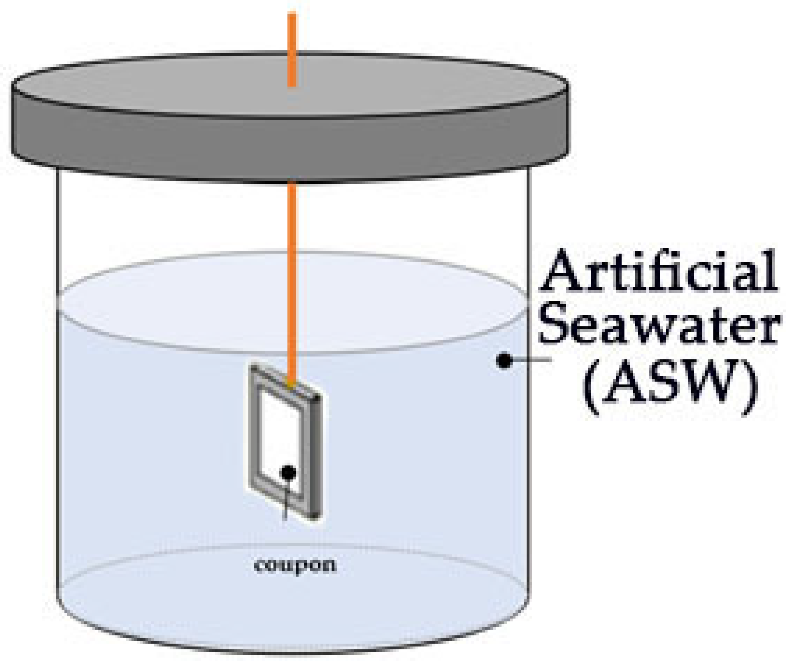
2.3. Laboratory Static Immersion Tests

Figure 2 illustrates that the long-term performance of the antifouling paint was initially assessed in laboratory conditions by static immersion testing in artificial seawater (ASW) [38]. The static laboratory immersion tests in ASW complied with the ASTM D1141 [39] and ASTM G 31-72 [40] standards.
Six naval steel samples were covered with antifouling paint for the laboratory tests (L0–L6 in Figure 2). Each coupon was positioned within an appropriately designed container (Figure 3) that was filled with ASW. The coupons were positioned at a depth of 3.5 cm below the surface of the ASW.
The immersion duration differed among the six samples and is presented in Table 3. Static immersion studies were also conducted on uncoated materials (L00–L06 in Figure 2) for the same duration for comparative analysis. The temperature was consistently maintained at 27 °C during the laboratory immersion tests.
Upon concluding their duration in ASW, the samples were meticulously removed from their container and air-dried. Each sample was subsequently weighed using digital precision scales to ascertain the weight variation before and after immersion, serving as an indicator for assessing the corrosion rate of naval steel [40]. The mass of each sample was measured thrice, and the mean was documented. The methodology for assessing the corrosion rate by the weight variation in the examined sample is detailed elsewhere [38]. A morphological analysis of the surface and cross-section of the samples post-immersion was conducted utilizing a scanning electron microscope (SEM). The percentage covering of the surface with corrosion products was assessed using (Image-Pro Analyzer software (Image-Pro® Plus Version 7.0 for Windows™), aided by the acquired photos. The aforementioned measurements were conducted on both coated and uncoated steel samples.
To compute the percentage of an area in a picture utilizing Image-Pro Analyzer, initially delineate the area of interest by creating a freehand selection around the corroded region. Subsequently, with the software’s integrated features [41], it may quantify the area and compute its percentage relative to the overall area of the image.
The conductivity of the antifouling coating was verified by Atomic Force Microscope equipped with an extended Tunneling Atomic Force Microscopy (TUNA) module. For conductivity mapping, the current sensitivity was set to 1 nA/V.
The water contact angles of the coated sample subjected to static laboratory immersion tests in ASW were assessed utilizing a contact angle goniometer (DSA 10-MK2, A. Krüss Optronic GmBH, Humburg, Germany). The coated samples were dried in ambient conditions before the measurements were conducted. DI water was dropped on three different places of the coated surface and the contact angles were measured at 30 s intervals for a total of 180 s. The mean values from three measurements were computed and documented.

2.4. In Situ Static Immersion Tests

To perform static immersion tests in seawater under real conditions, 18 naval steel samples were gathered and categorized into three groups of six samples each. In early May 2024, each sample group was immersed at a distinct location along the Greek shoreline (Figure 4). All samples in the collection were collected at six specified time intervals: 1 week, 2 weeks, 8 weeks, 17 weeks, 26 weeks, and 50 weeks. Subsequent to extraction, the samples were collected from the marine environment and maintained in the laboratory at room temperature for five days. Alongside the coated samples, uncoated steel samples were concurrently immersed at same time intervals to facilitate a comparison of biofouling rates. The samples were designated based on the methodology of the static immersion laboratory tests (Table 3), with the exception that the letter L was substituted with the letter S.
Each sample extracted from the immersion site after the specified duration in seawater was rinsed with deionized water and ethanol, and thereafter dried at ambient temperature. The macroscopic examination of the samples revealed the nature of the deposited micro- or macrofoulants. Likewise, the analysis of the acquired pictures allowed for the estimation of the biofilm volume fraction in both coated and uncoated steel samples.
The assessment of biofouling in the collected coated samples was performed by measuring the Foul Resistance (FR) and the Physical Data Rating (PDR) in accordance with the standards set out in ASTM D 3623 [42] and ASTM D 6990 [43].
The spectrum of FR values extends from 0 to 100. A score of 100 indicates a coated surface devoid of adhering biological foulants. In macro-colonization, the overall percentage of surface covered is deducted from 100, resulting in the FR representing the percentage of the surface devoid of fouling. As per ASTM D 6990, a rating of 99 indicates a paint layer devoid of macrofouling but either partially or wholly obscured by microfouling, irrespective of the surface coverage %.
The spectrum of PDR values spans from 0 to 100. A coated specimen exhibiting no physical deterioration is designated as 100. Upon cleaning the surface, the cumulative wear rates will be deducted from 100, yielding a figure that indicates the natural wear of the residual permeable coating. The Overall Performance (OP) score was the lesser value between the FR and PDR metrics.

3. Results

3.1. Characterization of the Antifouling Nanocomposites

FTIR spectroscopy studies were conducted to ascertain the conducting state of PAni and to examine the interactions between the polymer and titania in the PAni/TiO2 nanocomposite (Figure 5). The FTIR spectra of the PAni/TiO2 nanocomposite were recorded within the region of 500–3500 cm−1.
The FTIR spectrum of the PAni/TiO2 nanocomposite revealed all the main peaks of PAni along with the corresponding peaks of TiO2 (Table 4).
The presence of the principal peaks of PAni (C=C and C–N peaks), along with the Ti–O–Ti peak, signifies the incorporation of TiO2 into PAni. The effective interaction between TiO2 and PAni resulted in the coating of the nanotubes with TiO2 facilitated by the coordination of the nitrogen in PAni with TiO2 [44].
A small quantity of nanotubes was observed by TEM. The bright field image further confirmed the successful decoration of titanium oxide nanoparticles at the exterior of PAni’s nanotubes (Figure 6a). SEM micrographs illustrate nanocomposite PAni/TiO2 aggregates with an average size ranging from 200 to 700 μm (Figure 6b). Notably, pure PAni or TiO2 aggregates were undetected in the SEM analysis, suggesting that TiO2 in the PAni/TiO2 composite mostly decorates the surface of PAni.
The synergistic impact of PAni/TiO2 not only verifies the presence of titania to the polymer but also indicates that PAni is in its conductive state, as interactions between TiO2 necessitate the polymer’s conductivity [50]. Conductivity measurements revealed that the conductivity of pure PAni exhibited a marginal decrease within the PAni-TiO2 nanostructure, from 6.72 × 10⁻⁵ S cm−1 to 6.15 × 10⁻⁵ S cm−1, respectively. This alteration is ascribed to the higher concentration of defects [51].
The modification of MWCNFs with Fe3O4 was confirmed by using FTIR spectroscopy (Figure 7). The spectra revealed that there are several peaks presenting the functional groups of the MWCNT and the Fe3O4 (Table 5). Based on this characterization, it can be stated that carboxyl groups were successfully generated on the surface of the MWCNTs and attached the Fe3O4 nanoparticles.
Following the magnetic treatment of the MWCNTs, TEM bright field images distinctly revealed that the MWCNTs were adorned with Fe3O4 nanoparticles. A quantity of isolated nanoparticles appeared to have been randomly adsorbed onto the external surfaces of the MWCNTs (Figure 8a). SEM micrographs (Figure 8b) revealed that clustered MWCNTs/Fe3O4 complexes were predominantly spherical, enveloped by a dense magnetite nanoparticle structure exhibiting an uneven morphology.
The resulting antifouling coating exhibited modified polyaniline nanorods predominantly arranged vertically, whilst the functionalized carbon nanotubes with magnetite nanoparticles were developed in horizontally oriented overlaid layers (Figure 9).
The integration of conductive elements (PAni, MWCNTs) and their aligned arrangement in the final antifouling coating (Figure 9) enabled the development of structures demonstrating directional conductivity. The modulation of the conductivity properties of the final antifouling coating was performed using conductivity AFM (C-AFM) measurements (Figure 10). The existing flow is depicted by the black patches and/or dark areas in Figure 10a. The current flow is primarily focused inside the assessed surface of an enlarged region. The conductivity patches and topographic relief have been defined by extracting the current flow picture (Figure 10b) and the topographic image (Figure 10c) from the original acquired image (Figure 10a). The average roughness of the coating was determined to be approximately 200 nm (Figure 10b), while the simultaneously acquired current picture confirmed a surface current flow on the paint (Figure 10b). The current spots primarily manifest at the peripheries of the cavities of the surface protrusions, enabling effective electron transport along the antifouling coating (Figure 10b).

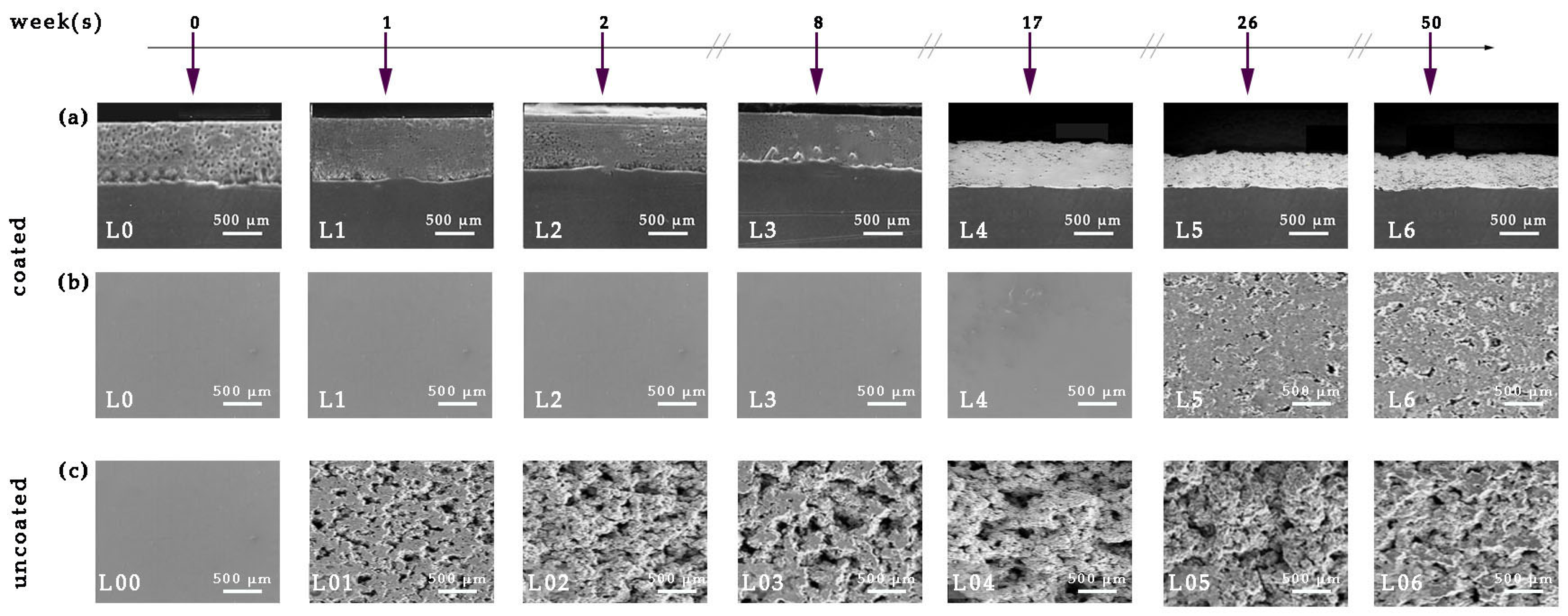
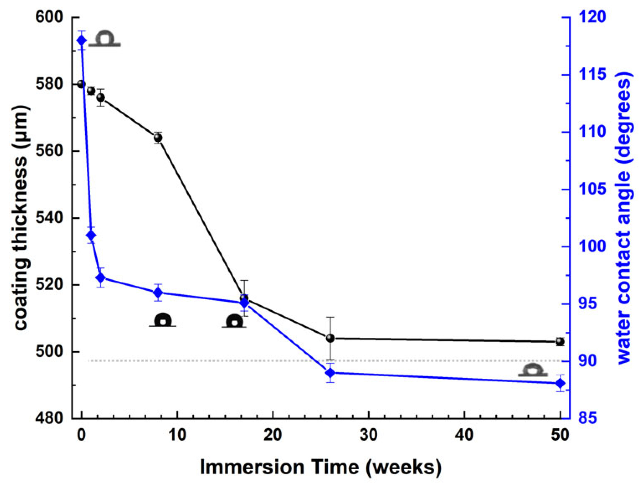
3.2. Corrosion Tests of Antifouling Coating

Static Immersion Tests

Figure 11 presents the SEM images of the surface and cross-section of the coated samples prior (0 weeks) to and following immersion in ASW, for various immersion times. Surface SEM’s micrographs of the uncoated steel samples are presented for comparative analysis.
Analysis of the cross-section micrographs of the coated specimens (Figure 11a(L0)–(L6)) reveals that, despite the absence of a primer or binder layer, the coating remains continuous and conforms to the topographical contours of the steel surface. Complete uniformity with the substrate signifies exceptional adhesive characteristics to the steel substrate. The antifouling coating layer is notably devoid of flaws, voids, or micro-cracks during its formation and is uniformly distributed across the surface of the metal substrate in the observed locations (Figure 11a). The coating layer is critically devoid of trapped pores, as well as longitudinal or transverse micro-cracks that could facilitate ASW adsorption and compromise the barrier properties of the coating. The antifouling coating–steel interface remains intact after 50 weeks of exposure to ASW (Figure 11a(L6)).
The coating thickness initially exhibits a minor reduction as the immersion duration extends to 8 weeks (Figure 12). The reduction in thickness with immersion time becomes increasingly evident until the 26th week of static immersion, which can be ascribed to the dissolving of the resin in artificial seawater owing to its water-soluble characteristics. During extended immersion times (26–50 weeks), the coating thickness remained virtually constant at approximately 510 μm.
Figure 12 illustrates the variation in the water contact angle (WCA) of the coated sample surface as the immersion period in artificial seawater (ASW) rises. During the preliminary phases of the coated sample’s immersion in ASW, the elevated contact angle is attributed to the hydrophobic characteristics of PAni [55] and MWCNTs [56,57]. As the immersion time in ASW extends and the resin dissolves in water due to its water-soluble properties, the hydrophilic structures of TiO2 και Fe3O4 are exposed, resulting in a reduced contact angle.
The coated steel specimens with antifouling coating exhibited initial indications of corrosion products after 17 weeks of continuous exposure to ASW (Figure 11b(L4)), whereas cracks and holes were not observed even after 50 weeks of exposure to ASW (Figure 11b(L6)). Conversely, examination of the surfaces of the uncoated samples (Figure 11c(L00)–(L06)) following the prolonged laboratory immersion test in ASW reveals that surface corrosion occurs within a brief immersion period (Figure 11c(L01)). As the immersion period in ASW extends, the initial corrosion product patches enlarge and become prevalent across the majority of the metal surface, with the emergence of holes and cracks (Figure 11c(L02)). After 8 weeks of immersion, the corrosion product aggregates had entirely enveloped the steel surface (Figure 11c(L03)). During extended static immersion periods in ASW (Figure 11c(L04)–(L06)), the corroded surface exhibits a significant accumulation of irregular network formations of corrosion products and a prominent topographical relief.
Figure 13 distinctly demonstrates the protective efficacy of the antifouling coating. With an increase in immersion time in ASW, the proportion of corrosion products on the surface of naval steel stays comparatively low relative to the uncoated samples (Figure 13a). Figure 13b illustrates the recorded corrosion depths for both coated and untreated steel specimens. The “unprotected” steel specimen exhibited substantial corrosion, impairing the functionality of the metal substrate.
In order to clarify the protective anticorrosion efficacy of the antifouling coating, the corrosion rates of both coated and untreated naval steel specimens were assessed by quantifying weight loss, a method noted for its simplicity, accuracy, and dependable reproducibility of results [38,58]. Table 6 illustrates the variation in weight and corrosion rate of the steel specimens over a 50-week immersion period in artificial seawater.
The lack of porosity, along with the adhesion retention to the steel substrate (Figure 11), improves the corrosion resistance of the epoxy coating and validates the barrier characteristics of the antifouling paint (Table 6). After one week of exposure to ASW, the corrosion rate of 21.401 mm/y in the uncoated specimen is reduced to zero in the coated specimen, indicating a 100% decrease. The substantial decrease in the corrosion rate is sustained after 2 weeks of exposure, achieving a value of 99.986% (from 14.996 mm/y to 0.002 mm/y). The corrosion rate reduction percentages for typical immersion durations of 8 and 17 weeks are 99.989% (decreasing from 9.597 mm/y to 0.001 mm/y) and 99.961% (decreasing from 6.273 mm/y to 0.002 mm/y), respectively. Finally, at high retention times this percentage ranges from 95.362% for 26 weeks retention (from 4.373 mm/y to 0.203 mm/y) and 91.835% for 50 weeks retention (from 2.328 mm/y to 0.190 mm/y).
Table 6 demonstrates that the decrease in metal mass (w) and the percentage weight change (w%) increased progressively with extended immersion time in the uncoated steel specimens. The corrosion rate (CR) decreases exponentially with immersion duration, exhibiting significant rates in the initial weeks and subsequently stabilizing after 26 weeks, suggesting that the corrosion layer acts as a protective barrier for naval steel. The immersion of uncoated steel samples in ASW instigates detrimental and unintended corrosion of the surface at a rate of 21.4 mm/y. As immersion duration increases, the surface coverage rises (Figure 13a) and the corrosion thickness intensifies (Figure 12), leading to a decrease in the corrosion rate from 15 mm/y to 6.3 mm/y. Upon complete corrosion of the steel surface (100% coverage in Figure 13a) and the stabilization of corrosion product thickness (Figure 13b), the corrosion rate shows a slight decrease of 2 mm/y; however, it continues to cause surface damage due to the presence of micro- and macro-pits (Figure 11c(L05)–(L06)).
In contrast, the weight change (w) for the coated specimens is negligible up to 17 weeks of immersion, and after 50 weeks in artificial seawater, the weight has decreased by merely 1.7%. Until the 17th week of immersion, absence of notable weight change yields a corrosion rate of zero; thereafter, for a duration of up to 50 weeks in artificial seawater, the corrosion rate remains remarkably low and almost constant. The coated samples with the antifouling coating demonstrate outstanding corrosion resistance on naval steel surfaces. The negligible weight alteration and the ease of removing corrosion products from the coating’s surface demonstrate its superior anti-stick properties and corrosion resistance.

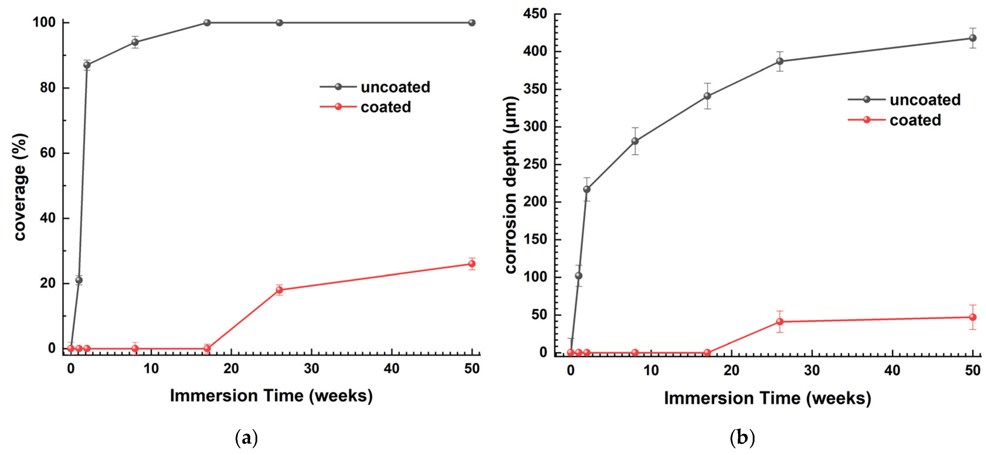
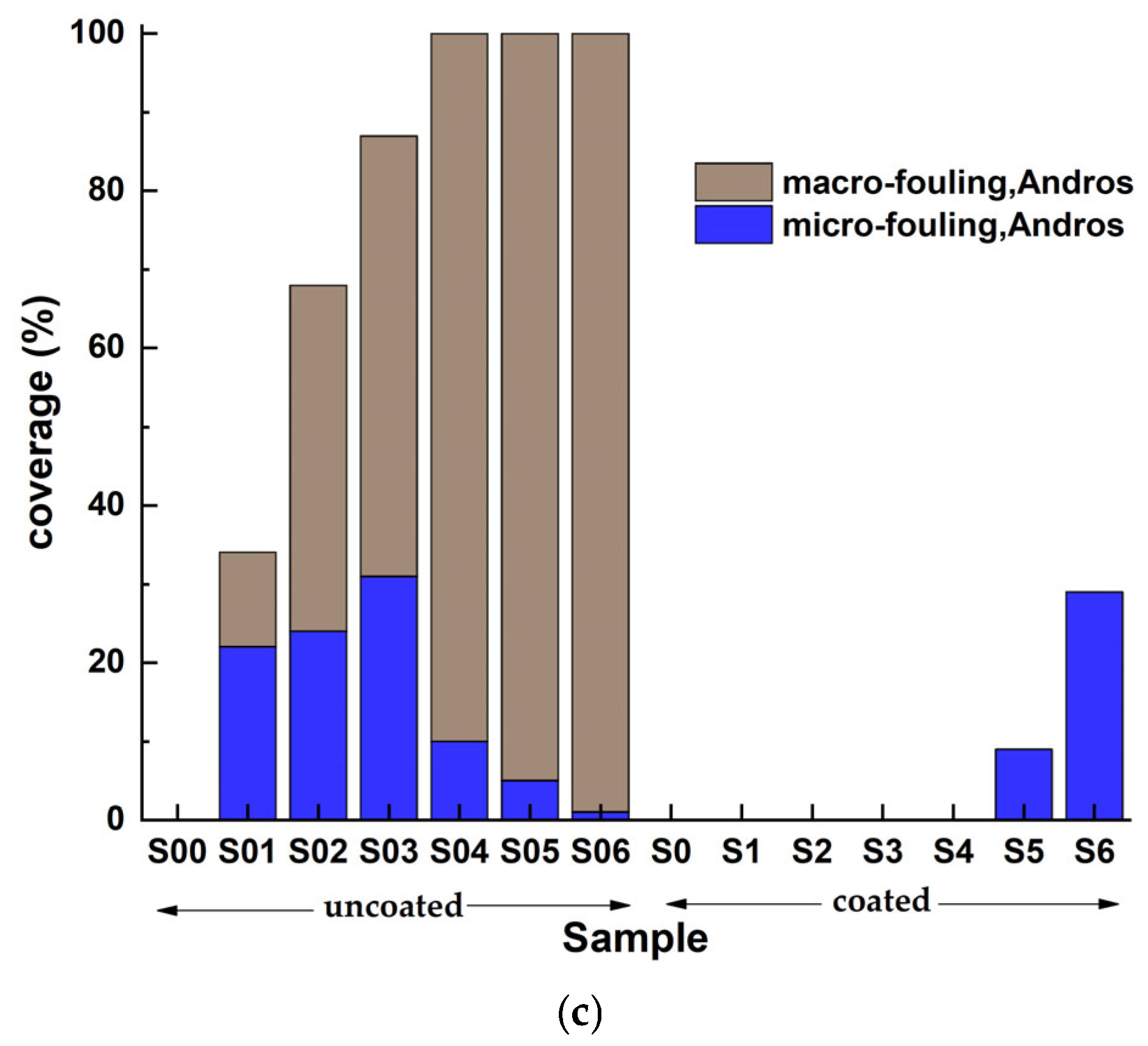
3.3. On-Site Immersion of Steels in Real Seawater

The nature, characteristics and intensity of fouling can differ depending on the duration of a metal surface’s exposure to seawater and the site of immersion. Consequently, the coated surfaces were evaluated for performance under different fouling conditions in three distinct locations: Rafina, Kalamata, and Andro.
Figure 14 displays macroscopic digital images of both coated and uncoated naval steel samples, intended for visual assessment at the time intervals outlined in Table 3. The macroscopic analysis of the photos reveals notable and substantial differences in biofouling across the three locations (Rafina, Kalamata, and Andro) concerning foulant frequency, colonizing species, and the timing of their emergence.
All coated naval steel samples demonstrated the presence of both incipient and advanced slime starting from the 17th week of immersion, with the exception of the Andros Sea, where slime became apparent only after the 26th week of immersion in seawater. This is likely attributable to the modest marine fouling that defines the region. At prolonged immersion durations (exceeding 26 weeks), the antifouling coating failed to inhibit soft microfouling. Nonetheless, the quantity of preserved microfouling organisms was little. No macrofouling of the coated sample surface was found at any of the three selected immersion sites (Rafina, Kalamata, and Andro).
The predominant species responsible for surface fouling on the uncoated naval steel samples were tunicates, bryozoans, branching algae, and spiny algae, with hard-shelled organisms appearing in all cases following the 8th week of immersion. Following 17 weeks of exposure to seawater, the pictures in Figure 14 indicate minimal visual distinctions across the selected immersion sites.
The visual examination of coated and uncoated samples, considering edge effects, led to the assessment of the percentage coverage of the exposed surface obscured by foulants. Figure 15 quantifies the coverage percentages of the samples’ surfaces (coated and uncoated) by micro- and macro-organisms associated with marine fouling.
The coated samples exhibit effective suppression of macro- and micro-colonization for the majority of micro-organisms until the 17th week of immersion in the corresponding marine environment. The antifouling coating demonstrates efficacy as a protective payer against slime mold, since its presence remains inconspicuous and limited, even after 26 weeks of immersion. In all instances, the coverage does not surpass 30% of the surface following the 50th week of residency. The uncoated samples exhibit greater coverage percentages compared to the coated samples. The deposition rate of foulants is swift and entails both micro- and macro-colonization, especially from the 17th week of immersion in seawater.
The efficiency of the antifouling coating was quantitatively assessed using the metrics of the percentage of the coating system free from biofouling organisms (fouling rate, FR) and the percentage of the coating surface area impacted by physical damage (physical damage rate, PDR). The findings from all three locations are displayed in Table 7.
The variation in the antifouling efficacy of the coating system indicates that the lack of macrofouling results in exceptionally high FR rates. The simplicity of detaching the accumulated microfouling post-rinsing of the samples indicates the anti-adhesive (or anti-stick) characteristics of the antifouling coating, as evidenced by the recorded maximum value (100%) of the PDR parameter. An effective antifouling system is defined by an OP value exceeding 80%, indicating that a biocide-free antifouling coating is adequate for the protection of naval steels.

4. Discussion

The experimental findings of this study indicate that the antifouling coating serves as a protective anticorrosive and antifouling layer on naval steel samples. The antifouling coating consists of two distinct nanocomposites: PAni/TiO2 and MWCNTs/Fe3O4. Each component contributes to the antifouling coating, unique characteristics when immersion in either artificial or natural seawater.
During the preliminary stages of immersion (immersion duration < 8 weeks), the antifouling coating preserves its thickness (Figure 12). The results from the TEM examination (Figure 9) indicate that the titania-decorated polyaniline nanorods are predominantly oriented vertically relative to the coating surface, whereas the magnetite-modified MWCNTs exhibit a horizontal alignment. The notable water contact angle values of the antifouling coating during the initial immersion stages (Figure 12) corroborates its hydrophobic properties, which may be ascribed to either PAni or MWCNTs [59,60]. Nevertheless, the modification of MWCNTs with magnetite and the comprehensive coating of their surfaces with magnetic nanoparticles (Figure 8) suggest that the hydrophobicity is attributed to the presence of the PAni, in the absence of any externally applied magnetic field [61].
The polyaniline is in its conductive state, as verified by four-probe conductivity measurements on PAni/TiO2, Conductive Atomic Force Microscopy (C-AFM) measurements in the antifouling coating (Figure 10) and FTIR spectrum of the PAni/TiO2 nanocomposite (Figure 5). The PAni’s electronic conductivity is sustained for an extended period, as the presence of TiO2 on the exterior of the PAni nanotubes and its doping with HCl inhibit the dissolution of anionic impurities of the conducting polymer in seawater [62].
Primary colonization foulants are defined by an accumulated negative electrostatic charge, attributed to the presence of macromolecules, phosphoryl, and carboxylic substituents in their external layer [63]. When attempting to bond with the antifouling coating, the electrostatic attraction between the matrix and foulants diminishes, ideally preventing the initiation of biofouling (Figure 15). Thus, the conductive properties of polyaniline impart antifouling features to the matrix and, consequently, to the hydrophobic coating (Figure 12).
As the duration of exposure to seawater extends, the resin dissolves, exposing portions of the PAni/TiO2 nanorods. The application of TiO2 on the polymer’s surface not only improves the conductivity characteristics of PAni, as previously noted, but also functions as a semiconducting n-type oxide that serves as an active catalyst for photocatalytic activities, leading to the in situ generation of H2O2 [64]. The non-toxic photocatalytic TiO2 enables the production of eco-friendly antifouling compounds that swiftly breakdown into H2O and O2 [65,66]. Consequently, during the preliminary phases of corrosion in laboratory settings, the corrosion rates in coated samples are notably minimal (Table 6). The photocatalysis mechanism is expected to be weaker in the submerged samples within the marine environments of Rafina, Kalamata, and Andros, due to the absence of diffuse light at the depths where the coated samples were situated.
As parts of the titania, noted for its hydrophilic properties, are revealed, the water contact angle values begin to diminish but remains above 90 degrees. Consequently, the surface of the antifouling coating remains hydrophobic and consistently demonstrates poor wettability. Consequently, the resin matrix’s water absorption is reduced, and its solubilization transpires in a controlled manner, thereby prolonging the durability of the antifouling coating even in static settings (Table 3, Figure 14 and Figure 15).
Following the 17th week in seawater, the coating’s thickness has diminished (Figure 12). The resin’s dissolution exposes sections of the PAni/TiO2 nanorods as well as the MWCNTs/Fe3O4 nanocomposite, hence decreasing the water contact angle values (Figure 12) due to the existence of the hydrophilic magnetite nanoparticles. A decrease in the contact angle enhances wettability and subsequently accelerates the dissolving rate of the resin. Following the removal of the resin, any precipitated corrosion products adhering to its surface are also eliminated, revealing a pristine layer of “virgin” coating (Figure 11). This newly exposed layer is characterized by a reduced surface corrosion rate, even after extended exposure to ASW (Figure 13, Figure 14 and Figure 15).
The incorporation of MWCNTs/Fe3O4 in their horizontal crosslinking (Figure 9) enhances the mechanical strength of the antifouling coating, ensuring compatibility with the steel’s substrate (Figure 11) and providing robust barrier properties to the antifouling coating (Figure 15), while minimizing water permeability to the steel surface (low CR values in Table 3).
Table 8 summarizes the contribution of each individual nanocomposite to the final antifouling coating.
The significant reduction in corrosion rates demonstrates the effectiveness of the coating in preventing corrosion relative to the untreated specimen (Figure 13). The specified coating system is notable for its absence of a priming layer, which is often present in commercial coatings to facilitate adhesion and bolster the corrosion resistance between the steel surface and the antifouling paint [11,67,68].
The coating’s performance during static immersion in seawater exhibits a consistent rate of 99%, as per a quantitative model established in international standards (Table 7). This efficiency, while elevated, was noted in marine habitats characterized by mild to intermediate biofouling pollution. Nonetheless, it is crucial to note that while the degree and nature of pollution in the uncoated samples were consistent at each time interval throughout the 50-week trial, the coated samples shown remarkable resistance to macrofouling overlap and exhibited distinct behavior in addressing microfouling (Figure 15).
Thus, the results under submerged site conditions reveal that the antifouling efficacy of the coating exhibits remarkable persistence of the coated naval steel over an extended period. The multifunctional coating effectively addresses the needs for antifouling protection while simultaneously providing corrosion protection for the metal substrate.
Table 9 presents a comparison of the coating’s functioning with commercially available antifouling coatings in the Greek market, which were either subjected to immersion in the marine environment of Rafina or laboratory-corroded in a 3.5% NaCl solution [17].
The antifouling coatings demonstrate superior performance compared to their commercial equivalents, both in laboratory and natural immersion settings. It is important to acknowledge that the size of the coated samples utilizing commercial antifouling coatings were greater than those in the current investigation, and the immersion process was conducted at different intervals.
The antifouling coating is environmentally safe and exhibits excellent antifouling efficacy, durability, and mechanical resistance, in accordance with the criteria specified in Table 2. Despite its ease of application, the formulation process is intricate and necessitates specialized skills, resulting in somewhat expensive production costs.
Nonetheless, it is essential to evaluate the long-term efficacy of the antifouling coating in hostile (aggressive) maritime settings, where suboptimal broad-spectrum performance may manifest. Comprehensive field testing across diverse water, temperature, and pH conditions is essential to assess the coating’s degradation over time. Furthermore, the intricacy of producing the coating system must be alleviated to ensure that the production of the refining system remains efficient and economical. It is also essential to verify compliance with stringent environmental safety standards to mitigate any long-term environmental consequences.

5. Conclusions

This study illustrates the efficacy of an antifouling coating on naval steel specimens, comprising two separate nanocomposites: PAni/TiO2 and MWCNTs/Fe3O4. The findings indicate that the antifouling coating functions as a protective anticorrosive barrier and antifouling layer on the surface of the naval steel samples. As the coating thickness decreases during static immersion, precipitated corrosion products are removed, revealing a new layer of “virgin” coating. This new layer demonstrates a reduced surface corrosion rate despite extended exposure to artificial seawater. The absence of porosity and retention of adhesion enhance the corrosion resistance of the coating and confirm the barrier properties of the antifouling paint.
Following one week of exposure to ASW, the corrosion rate of 21.401 mm/y in the uncoated specimen is diminished to zero in the coated specimen, signifying a 100% reduction. The significant reduction in the corrosion rate is maintained after 2 weeks of exposure, reaching a value of 99.986%. The coating demonstrates a continuous performance rate of 99% during static immersion in seawater. The coated samples exhibited notable resistance to macrofouling overlap and diverse responses to microfouling.
The conductive characteristics of polyaniline impart antifouling attributes to the hydrophobic coating. As the exposure time to seawater extends, the resin dissolves, revealing portions of the PAni/TiO2 nanotubes. The application of TiO2 on the polymer surface enhances the conductivity properties of PAni and serves as an active catalyst for photocatalytic processes. The functionalized MWCNTs with Fe2O3 provide anti-adhesion capabilities to the coating and enhance its cohesion with the steel substrate.
The antifouling coating is ecologically safe and demonstrates superior antifouling effectiveness, longevity, and mechanical resilience over a prolonged duration of immersion. The antifouling coating efficiently fulfills the requirements for antifouling protection while concurrently offering corrosion resistance for the metal substrate.
Nonetheless, comprehensive field testing under different sea sides, temperature, and pH conditions is necessary to evaluate the coating’s deterioration over time. The complexity of manufacturing the coating system must be simplified to provide efficient and cost-effective production, but adherence to rigorous environmental safety requirements is crucial to prevent long-term ecological impacts.

6. Patents

There is one patent resulting from the work reported in this manuscript: WO2024224120A1, Electrically anisotropic antifouling coatings, BFP Advanced Technologies, 2024 [37].

Author Contributions

Conceptualization, P.V. and N.D.P.; methodology, P.V. and N.D.P.; investigation, P.V.; data curation, P.P.F. and P.V.; writing—original draft preparation, P.V., P.P.F. and E.V.H.; supervision, N.D.P.; project administration, P.V. and N.D.P.; funding acquisition, N.D.P. All authors have read and agreed to the published version of the manuscript.

Funding

This research has been co-financed by the European Regional Development Fund of the European Union and Greek national funds through the Operational Program Competitiveness, Entrepreneurship, and Innovation, under the call RESEARCH—CREATE—INNOVATE (project code: T2EDK-00868).

Institutional Review Board Statement

Not applicable.

Informed Consent Statement

Not applicable.

Data Availability Statement

The original contributions presented in this study are included in the article. Further inquiries can be directed to the corresponding author.

Acknowledgments

The authors acknowledge precious help and technical assistance from colleagues working at Nanotechnology processes for solar energy conversion and environmental protection lab of INN/NCSRD.

Conflicts of Interest

Author Nikolaos D. Papadopoulos was employed by the company Department of Research and Development, BFP Advanced Technologies G.P., Athens. The remaining authors declare that the research was conducted in the absence of any commercial or financial relationships that could be construed as a potential conflict of interest.

Abbreviations

The following abbreviations are used in this manuscript:
AFantifouling
TBTtributyltin
CNTscarbon nanotubes
PAnipolyaniline
NPsnanoparticles
ASWartificial seawater
SEMscanning electron microscopy
FRFoul Resistance
PDRPhysical Data Rating
OPOverall Performance
CRcorrosion rate

References

  1. Yebra, D.M.; Kiil, S.; Dam-Johansen, K. Antifouling Technology—Past, Present and Future Steps towards Efficient and Environmentally Friendly Antifouling Coatings. Prog. Org. Coat. 2004, 50, 75–104. [Google Scholar] [CrossRef]
  2. Almeida, E.; Diamantino, T.C.; de Sousa, O. Marine Paints: The Particular Case of Antifouling Paints. Prog. Org. Coat. 2007, 59, 2–20. [Google Scholar] [CrossRef]
  3. Li, L.; Hong, H.; Cao, J.; Yang, Y. Progress in Marine Antifouling Coatings: Current Status and Prospects. Coatings 2023, 13, 1893. [Google Scholar] [CrossRef]
  4. Caruso, G. Microbial Colonization in Marine Environments: Overview of Current Knowledge and Emerging Research Topics. J. Mar. Sci. Eng. 2020, 8, 78. [Google Scholar] [CrossRef]
  5. Vinagre, P.A.; Simas, T.; Cruz, E.; Pinori, E.; Svenson, J. Marine Biofouling: A European Database for the Marine Renewable Energy Sector. J. Mar. Sci. Eng. 2020, 8, 495. [Google Scholar] [CrossRef]
  6. Clare, A.S.; Rittschof, D.; Gerhart, D.J.; Maki, J.S. Molecular Approaches to Nontoxic Antifouling. Invertebr. Reprod. Dev. 1992, 22, 67–76. [Google Scholar] [CrossRef]
  7. Vuong, P.; McKinley, A.; Kaur, P. Understanding Biofouling and Contaminant Accretion on Submerged Marine Structures. NPJ Mater. Degrad. 2023, 7, 50. [Google Scholar] [CrossRef]
  8. Cirillo, A.; Tomaiuolo, G.; Guido, S. Membrane Fouling Phenomena in Microfluidic Systems: From Technical Challenges to Scientific Opportunities. Micromachines 2021, 12, 820. [Google Scholar] [CrossRef]
  9. Martín-Rodríguez, A.J.; Babarro, J.M.F.; Lahoz, F.; Sansón, M.; Martín, V.S.; Norte, M.; Fernández, J.J. From Broad-Spectrum Biocides to Quorum Sensing Disruptors and Mussel Repellents: Antifouling Profile of Alkyl Triphenylphosphonium Salts. PLoS ONE 2015, 10, e0123652. [Google Scholar] [CrossRef]
  10. Weber, F.; Esmaeili, N. Marine Biofouling and the Role of Biocidal Coatings in Balancing Environmental Impacts. Biofouling 2023, 39, 661–681. [Google Scholar] [CrossRef]
  11. Sahoo, B.N.; Thomas, P.J.; Thomas, P.; Greve, M.M. Antibiofouling Coatings for Marine Sensors: Progress and Perspectives on Materials, Methods, Impacts, and Field Trial Studies. ACS Sens. 2025, 10, 1600–1619. [Google Scholar] [CrossRef] [PubMed]
  12. Jin, H.; Wang, J.; Tian, L.; Gao, M.; Zhao, J.; Ren, L. Recent Advances in Emerging Integrated Antifouling and Anticorrosion Coatings. Mater. Des. 2022, 213, 110307. [Google Scholar] [CrossRef]
  13. Papadopoulos, N.D.; Vourna, P.; Falara, P.P.; Koutsaftiki, P.; Xafakis, S. Dual-Function Coatings to Protect Absorbent Surfaces from Fouling. AIMS Mater. Sci. 2023, 10, 981–1003. [Google Scholar] [CrossRef]
  14. Schultz, M.P.; Walker, J.M.; Steppe, C.N.; Flack, K.A. Impact of Diatomaceous Biofilms on the Frictional Drag of Fouling-Release Coatings. Biofouling 2015, 31, 759–773. [Google Scholar] [CrossRef]
  15. Schultz, M.P. Effects of Coating Roughness and Biofouling on Ship Resistance and Powering. Biofouling 2007, 23, 331–341. [Google Scholar] [CrossRef]
  16. Papadopoulos, N.; Vourna, P.; Falara, P.; Vourna, P. A Modern Approach Towards Efficient Antifouling Coating Technologies. Nanotechnol. Adv. Mater. Sci. 2023, 6, 1–4. [Google Scholar] [CrossRef]
  17. Falara, P.P.; Papadopoulos, N.D.; Vourna, P. Microstructure and Performance of Antibiofouling Coatings on High-Strength Steel Substrates Immersed in the Marine Environment. Micro 2022, 2, 277–294. [Google Scholar] [CrossRef]
  18. Champ, M.A. A Review of Organotin Regulatory Strategies, Pending Actions, Related Costs and Benefits. Sci. Total Environ. 2000, 258, 21–71. [Google Scholar] [CrossRef]
  19. Paz-Villarraga, C.A.; Castro, Í.B.; Fillmann, G. Biocides in Antifouling Paint Formulations Currently Registered for Use. Environ. Sci. Pollut. Res. 2022, 29, 30090–30101. [Google Scholar] [CrossRef]
  20. Selim, M.S.; Shenashen, M.A.; El-Safty, S.A.; Higazy, S.A.; Selim, M.M.; Isago, H.; Elmarakbi, A. Recent Progress in Marine Foul-Release Polymeric Nanocomposite Coatings. Prog. Mater. Sci. 2017, 87, 1–32. [Google Scholar] [CrossRef]
  21. Chambers, L.D.; Stokes, K.R.; Walsh, F.C.; Wood, R.J.K. Modern Approaches to Marine Antifouling Coatings. Surf. Coat. Technol. 2006, 201, 3642–3652. [Google Scholar] [CrossRef]
  22. Banerjee, I.; Pangule, R.C.; Kane, R.S. Antifouling Coatings: Recent Developments in the Design of Surfaces That Prevent Fouling by Proteins, Bacteria, and Marine Organisms. Adv. Mater. 2011, 23, 690–718. [Google Scholar] [CrossRef] [PubMed]
  23. Farkas, A.; Degiuli, N.; Martić, I. An Investigation into the Effect of Hard Fouling on the Ship Resistance Using CFD. Appl. Ocean Res. 2020, 100, 102205. [Google Scholar] [CrossRef]
  24. Byrnes, T.A.; Dunn, R.J.K. Boating- and Shipping-Related Environmental Impacts and Example Management Measures: A Review. J. Mar. Sci. Eng. 2020, 8, 908. [Google Scholar] [CrossRef]
  25. Davidson, I.C.; Smith, G.; Ashton, G.V.; Ruiz, G.M.; Scianni, C. An Experimental Test of Stationary Lay-up Periods and Simulated Transit on Biofouling Accumulation and Transfer on Ships. Biofouling 2020, 36, 455–466. [Google Scholar] [CrossRef]
  26. Liu, P.; Zhang, H.; Fan, Y.; Xu, D. Microbially Influenced Corrosion of Steel in Marine Environments: A Review from Mechanisms to Prevention. Microorganisms 2023, 11, 2299. [Google Scholar] [CrossRef]
  27. Dafforn, K.A.; Lewis, J.A.; Johnston, E.L. Antifouling Strategies: History and Regulation, Ecological Impacts and Mitigation. Mar. Pollut. Bull. 2011, 62, 453–465. [Google Scholar] [CrossRef]
  28. Satasiya, G.; Kumar, M.A.; Ray, S. Biofouling Dynamics and Antifouling Innovations: Transitioning from Traditional Biocides to Nanotechnological Interventions. Environ. Res. 2025, 269, 120943. [Google Scholar] [CrossRef]
  29. Railkin, A.I. Marine Biofouling, 1st ed.; CRC Press: Boca Raton, FL, USA, 2003; ISBN 978-0-203-50323-2. [Google Scholar]
  30. Terlizzi, A.; Fraschetti, S.; Gianguzza, P.; Faimali, M.; Boero, F. Environmental Impact of Antifouling Technologies: State of the Art and Perspectives. Aquat. Conserv. 2001, 11, 311–317. [Google Scholar] [CrossRef]
  31. Omae, I. General Aspects of Tin-Free Antifouling Paints. Chem. Rev. 2003, 103, 3431–3448. [Google Scholar] [CrossRef]
  32. Wahl, M. Marine Epibiosis. I. Fouling and Antifouling: Some Basic Aspects. Mar. Ecol. Prog. Ser. 1989, 58, 175–189. [Google Scholar] [CrossRef]
  33. Canales, C.; Galarce, C.; Rubio, F.; Pineda, F.; Anguita, J.; Barros, R.; Parragué, M.; Daille, L.K.; Aguirre, J.; Armijo, F.; et al. Testing the Test: A Comparative Study of Marine Microbial Corrosion under Laboratory and Field Conditions. ACS Omega 2021, 6, 13496–13507. [Google Scholar] [CrossRef] [PubMed]
  34. Periyasamy, T.; Raorane, C.J.; Haldhar, R.; Asrafali, S.P.; Kim, S.-C. Development of Arbutin Based Sustainable Polybenzoxazine Resin for Antifouling and Anticorrosion of Low Carbon Steel. Prog. Org. Coat. 2022, 170, 106968. [Google Scholar] [CrossRef]
  35. Balakrishnan, A.; Govindaraj, S.; Dhaipule, N.G.K.; Thirumalaisamy, N.; Anne, R.S.; Sublime, N.; Philip, J. Enhancing Microbiologically Influenced Corrosion Protection of Carbon Steels with Silanized Epoxy-Biocide Hybrid Coatings. Environ. Sci. Pollut. Res. 2024, 31, 13302–13326. [Google Scholar] [CrossRef]
  36. Eduok, U.; Suleiman, R.; Gittens, J.; Khaled, M.; Smith, T.J.; Akid, R.; El Ali, B.; Khalil, A. Anticorrosion/Antifouling Properties of Bacterial Spore-Loaded Sol–Gel Type Coating for Mild Steel in Saline Marine Condition: A Case of Thermophilic Strain of Bacillus Licheniformis. RSC Adv. 2015, 5, 93818–93830. [Google Scholar] [CrossRef]
  37. BFP Advanced Technologies. Electrically Anisotropic Antifouling Coatings. WO2024224120A1, 31 October 2024. [Google Scholar]
  38. Vourna, P.; Papadopoulos, N.D.; Falara, P.P.; Hristoforou, E. Barkhausen Noise Emission of Naval Steel: The Impact of Seawater Corrosion Coverage and Depth. NDT E Int. 2025, 151, 103319. [Google Scholar] [CrossRef]
  39. ASTM D1141; Standard Specifications for Substitute Ocean Water. ASTM International: West Conshohocken, PA, USA, 1960; pp. 398–399.
  40. ASTM G31-72; Standard Practice for Laboratory Immersion Corrosion Testing of Metals. ASTM: West Conshohocken, PA, USA, 2004.
  41. Media Cybernetics IMAGE-PRO® Discovery: The Enhanced Image Analysis Solution from the Image-Pro Family. Available online: https://www.digitalimagingsystems.co.uk/pdfs/image-pro-discovery.pdf (accessed on 16 June 2025).
  42. ASTM 3626; Test Method for Testing Antifouling Panels in Shallow Submergence. ASTM: West Conshohocken, PA, USA, 2020. [CrossRef]
  43. ASTM D 6990; Practice for Evaluating Biofouling Resistance and Physical Performance of Marine Coating Systems. ASTM: West Conshohocken, PA, USA, 2020. [CrossRef]
  44. Hashemi Monfared, A.; Jamshidi, M. Synthesis of Polyaniline/Titanium Dioxide Nanocomposite (PAni/TiO2) and Its Application as Photocatalyst in Acrylic Pseudo Paint for Benzene Removal under UV/VIS Lights. Prog. Org. Coat. 2019, 136, 105257. [Google Scholar] [CrossRef]
  45. Gilja, V.; Novaković, K.; Travas-Sejdic, J.; Hrnjak-Murgić, Z.; Kraljić Roković, M.; Žic, M. Stability and Synergistic Effect of Polyaniline/TiO2 Photocatalysts in Degradation of Azo Dye in Wastewater. Nanomaterials 2017, 7, 412. [Google Scholar] [CrossRef]
  46. Deivanayaki, S.; Ponnuswamy, V.; Ashokan, S.; Jayamurugan, P.; Mariappan, R. Synthesis and Characterization of TiO2-Doped Polyaniline Nanocomposites by Chemical Oxidation Method. Mater. Sci. Semicond. Process. 2013, 16, 554–559. [Google Scholar] [CrossRef]
  47. Shao, W.; Jamal, R.; Xu, F.; Ubul, A.; Abdiryim, T. The Effect of a Small Amount of Water on the Structure and Electrochemical Properties of Solid-State Synthesized Polyaniline. Materials 2012, 5, 1811–1825. [Google Scholar] [CrossRef]
  48. Butoi, B.; Groza, A.; Dinca, P.; Balan, A.; Barna, V. Morphological and Structural Analysis of Polyaniline and Poly(o-Anisidine) Layers Generated in a DC Glow Discharge Plasma by Using an Oblique Angle Electrode Deposition Configuration. Polymers 2017, 9, 732. [Google Scholar] [CrossRef] [PubMed]
  49. Jarvin, M.; Rosaline, D.R.; Gopalakrishnan, T.; Kamalam, M.B.R.; Foletto, E.L.; Dotto, G.L.; Inbanathan, S.S.R. Remarkable Photocatalytic Performances towards Pollutant Degradation under Sunlight and Enhanced Electrochemical Properties of TiO2/Polymer Nanohybrids. Environ. Sci. Pollut. Res. 2023, 30, 62832–62846. [Google Scholar] [CrossRef] [PubMed]
  50. Lin, Y.; Li, D.; Hu, J.; Xiao, G.; Wang, J.; Li, W.; Fu, X. Highly Efficient Photocatalytic Degradation of Organic Pollutants by PANI-Modified TiO2 Composite. J. Phys. Chem. C 2012, 116, 5764–5772. [Google Scholar] [CrossRef]
  51. Žic, M. The Influence of the PANI Structure on the Conductive Mechanism and on the Electrical Equivalent Circuit Analysis. J. Electroanal. Chem. 2009, 635, 29–38. [Google Scholar] [CrossRef]
  52. Stegarescu, A.; Cabrera, H.; Budasheva, H.; Soran, M.-L.; Lung, I.; Limosani, F.; Korte, D.; Amati, M.; Borodi, G.; Kacso, I.; et al. Synthesis and Characterization of MWCNT-COOH/Fe3O4 and CNT-COOH/Fe3O4/NiO Nanocomposites: Assessment of Adsorption and Photocatalytic Performance. Nanomaterials 2022, 12, 3008. [Google Scholar] [CrossRef]
  53. Zhao, Z.; Yang, Z.; Hu, Y.; Li, J.; Fan, X. Multiple Functionalization of Multi-Walled Carbon Nanotubes with Carboxyl and Amino Groups. Appl. Surf. Sci. 2013, 276, 476–481. [Google Scholar] [CrossRef]
  54. Abdullah, T.A.; Juzsakova, T.; Rasheed, R.T.; Salman, A.D.; Sebestyen, V.; Domokos, E.; Sluser, B.; Cretescu, I. Polystyrene-Fe3O4-MWCNTs Nanocomposites for Toluene Removal from Water. Materials 2021, 14, 5503. [Google Scholar] [CrossRef]
  55. Chen, C.-Y.; Huang, S.Y.; Wan, H.-Y.; Chen, Y.-T.; Yu, S.-K.; Wu, H.-C.; Yang, T.-I. Electrospun Hydrophobic Polyaniline/Silk Fibroin Electrochromic Nanofibers with Low Electrical Resistance. Polymers 2020, 12, 2102. [Google Scholar] [CrossRef]
  56. Chen, X.; Gao, J.; Song, Y.; Gong, Y.; Qi, M.; Hao, R. Fabrication of a High Water Flux Conductive MWCNTs/PVC Composite Membrane with Effective Electrically Enhanced Antifouling Behavior. Coatings 2021, 11, 1548. [Google Scholar] [CrossRef]
  57. Alterary, S.S.; Alyabes, R.M.; Alshahrani, A.A.; Al-Alshaikh, M.A. Unfunctionalized and Functionalized Multiwalled Carbon Nanotubes/Polyamide Nanocomposites as Selective-Layer Polysulfone Membranes. Polymers 2022, 14, 1544. [Google Scholar] [CrossRef]
  58. Malaret, F. Exact Calculation of Corrosion Rates by the Weight-Loss Method. Exp. Results 2022, 3, e13. [Google Scholar] [CrossRef]
  59. Sousa-Cardoso, F.; Teixeira-Santos, R.; Mergulhão, F.J.M. Antifouling Performance of Carbon-Based Coatings for Marine Applications: A Systematic Review. Antibiotics 2022, 11, 1102. [Google Scholar] [CrossRef]
  60. Wang, N.; Zhang, R.; Liu, K.; Zhang, Y.; Shi, X.; Sand, W.; Hou, B. Application of Nanomaterials in Antifouling: A Review. Nano Mater. Sci. 2024, 6, 672–700. [Google Scholar] [CrossRef]
  61. Esteves, D.S.; Melo, A.; Alves, S.; Durães, N.; Paiva, M.C.; Sequeiros, E.W. Magnetic Field-Assisted Orientation and Positioning of Magnetite for Flexible and Electrically Conductive Sensors. Micromachines 2025, 16, 68. [Google Scholar] [CrossRef] [PubMed]
  62. Lee, Y.-J.; Lee, H.S.; Lee, C.-G.; Park, S.-J.; Lee, J.; Jung, S.; Shin, G.-A. Application of PANI/TiO2 Composite for Photocatalytic Degradation of Contaminants from Aqueous Solution. Appl. Sci. 2020, 10, 6710. [Google Scholar] [CrossRef]
  63. Han, S.-J.; Park, J.-S. Understanding Membrane Fouling in Electrically Driven Energy Conversion Devices. Energies 2021, 14, 212. [Google Scholar] [CrossRef]
  64. Villardi De Oliveira, C.; Petitbois, J.; Faÿ, F.; Sanchette, F.; Schuster, F.; Alhussein, A.; Chaix-Pluchery, O.; Deschanvres, J.-L.; Jiménez, C. Marine Antibiofouling Properties of TiO2 and Ti-Cu-O Films Deposited by Aerosol-Assisted Chemical Vapor Deposition. Coatings 2020, 10, 779. [Google Scholar] [CrossRef]
  65. Yi, P.; Jia, H.; Yang, X.; Fan, Y.; Xu, S.; Li, J.; Lv, M.; Chang, Y. Anti-Biofouling Properties of TiO2 Coating with Coupled Effect of Photocatalysis and Microstructure. Colloids Surf. A Physicochem. Eng. Asp. 2023, 656, 130357. [Google Scholar] [CrossRef]
  66. Iesalnieks, M.; Eglītis, R.; Juhna, T.; Šmits, K.; Šutka, A. Photocatalytic Activity of TiO2 Coatings Obtained at Room Temperature on a Polymethyl Methacrylate Substrate. Int. J. Mol. Sci. 2022, 23, 12936. [Google Scholar] [CrossRef]
  67. Kordas, G. Novel Antifouling and Self-Healing Eco-Friendly Coatings for Marine Applications Enhancing the Performance of Commercial Marine Paints. In Engineering Failure Analysis; Thanapalan, K., Ed.; IntechOpen: Rijeka, Croatia, 2020; ISBN 978-1-78985-945-4. [Google Scholar]
  68. Chen, Q.; Zhang, Z.; Qi, Y. Construction of a Novel Environmentally-Friendly Long-Term Antifouling Coating with a Double-Layer Structure Regulated by Phenylmethyl Silicone Oil and Verification of the Static Antifouling Performance of the Coating. Surf. Interfaces 2025, 56, 105519. [Google Scholar] [CrossRef]
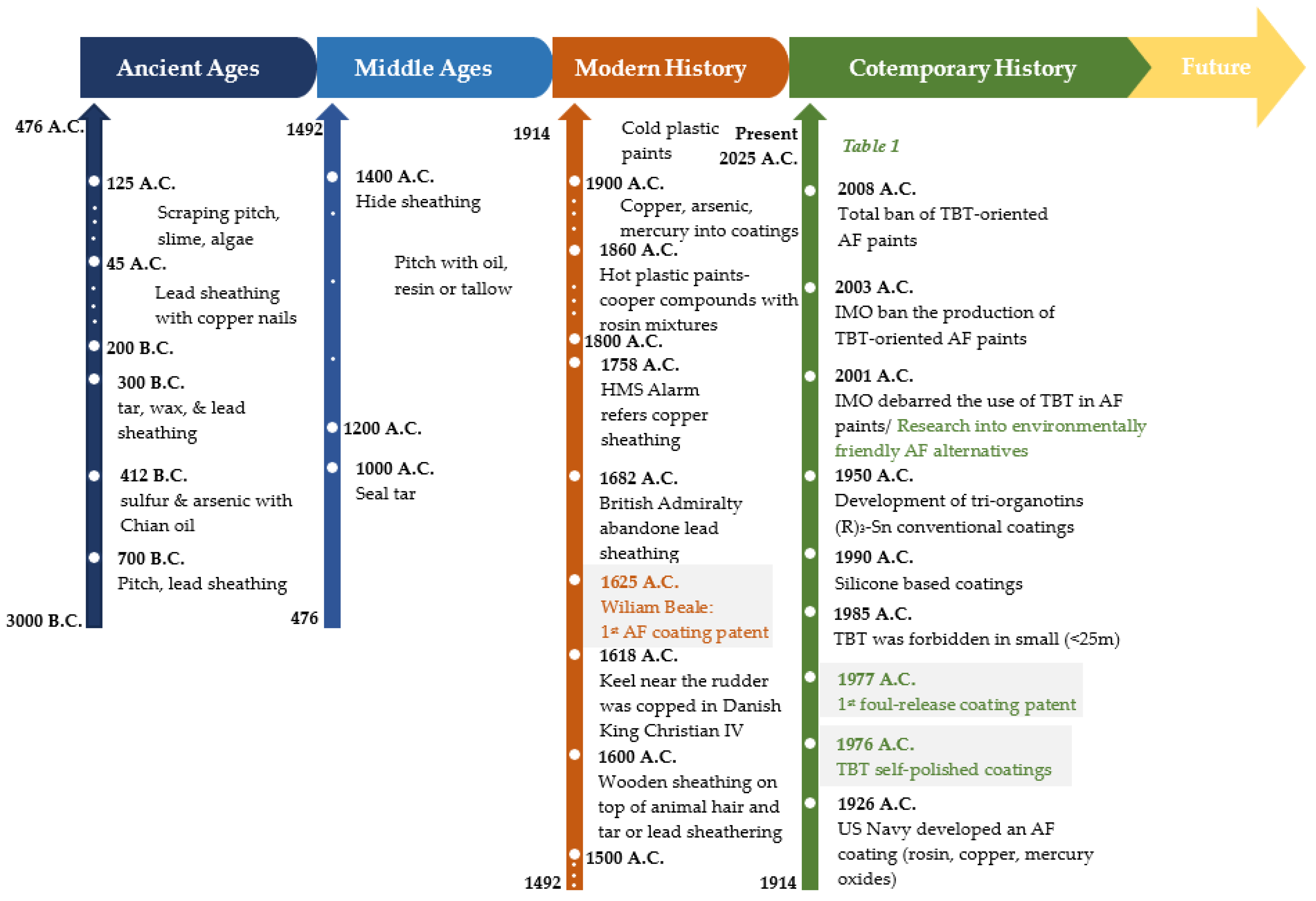
Figure 2. Diagram illustrating the experimental protocol for the corrosion evaluation of uncoated and coated steels.
Materials 18 03095 g002
Figure 3. Apparatus used in the laboratory static immersion test. The orange line denotes a non-conductive coupon retention cord.
Materials 18 03095 g003
Figure 4. Location and satellite photos of the (a) Rafina, (b) Kalamata, and (c) Andro exposure sites for coated and uncoated naval steel panels. Red pins on a map indicate the precise location of the specific places.
Materials 18 03095 g004
Figure 5. FTIR spectra of PAni/TiO2 nanocomposite.
Materials 18 03095 g005
Figure 6. (a) TEM’s bright field image and (b) SEM micrograph of functionalized PAni nanorods with TiO2 NPs.
Materials 18 03095 g006
Figure 7. FTIR spectra of the modified MWCNFs with Fe3O4.
Materials 18 03095 g007
Figure 8. (a) TEM’s bright field image and (b) SEM micrograph of functionalized carbon nanotubes with magnetite NPs.
Materials 18 03095 g008
Figure 9. TEM’s bright field image antifouling coating.
Materials 18 03095 g009
Figure 10. (a) Conductive AFM mapping of the antifouling coating, (b) topography image, and (c) current map at 10 mV DC sample bias.
Materials 18 03095 g010
Figure 11. SEM micrographs of (a,b) coated and (c) uncoated naval steel samples following their static immersion in ASW. (a) Cross-section and (b,c) surface images. The designation in the lower left corner of each subfigures (LX or L0X, where X ranges from 1 to 6) corresponds to the sample names shown in Table 3.
Materials 18 03095 g011
Figure 12. Measurements of coating thickness and water contact angle (WCA) as a function of immersion duration in artificial seawater (ASW). The dotted line at 90 degrees signifies the change from hydrophobic behavior (WCA > 90 degrees) to hydrophilic behavior (WCA < 90 degrees). Representative digital photos of water droplets on the coated steel samples are also presented in the figure.
Materials 18 03095 g012
Figure 13. (a) Percentage of surface coverage with foulants on samples immersed in artificial seawater (ASW) and (b) corrosion depth of corrosion products as a function of immersion duration in ASW for both coated and uncoated naval steel samples.
Materials 18 03095 g013
Figure 14. Indictive digital photographs of coated and uncoated naval steel panels submerged at seawater at three locations: (a) Rafina, (b) Kalamata, and (c) Andros.
Materials 18 03095 g014
Figure 15. Micro- and macrofouling on uncoated and coated naval steel samples submerged at three locations: (a) Rafina, (b) Kalamata, and (c) Andros.
Materials 18 03095 g015aMaterials 18 03095 g015b
Table 1. Antifouling strategies on ship hulls and their advantages and disadvantages.
PeriodTechnologyAdvantagesDisadvantages
<1800 A.D.Pitch, organic residues (oil), copper foilNatural protection, easy applicationLimited durability, environmentally unstable
1800–1950Copper and lead-based marine paintsEffective, commercially availableToxic to aquatic organisms
1960–2000Paints with tributyltin (TBT)Very high effectivenessVery toxic
Worldwide ban in 2008
2000–todaySelf-polishing copolymers (SPCs)Controlled release of biocides, stable performanceStill contain copper or other mild biocides
2010–todaySilicone-based/fluoropolymer-based hydrophobic paintsBiocide free, very smooth surface, environmentally friendlyMore precise, require high surface preparation
2015–todayBiomimetic surfaces
(e.g., SharkletTM, Aurora, CO, USA)
Chemical-free antifouling actionIn development—cost, durability
2020–todayRobotic cleaners
(π.χ. HullWiper (Dubai, United Arab Emirates), ECOsubsea (Torangsvåg, Norway))
No chemicals, repeated useRequires frequent application—limitations in ports
2020–todayUV illumination/electrochemical methodsFully non-chemical solutionsExperimental stage
Table 3. Designation of naval steel samples in static immersion tests.
Sample Notation
for Laboratory Tests
Sample Notation
for In Situ Tests
Immersion Time
(Weeks)
Uncoated
samples
L00S000
L01S011
L02S022
L03S038
L04S0417
L05S0526
L06S0650
Coated
samples
L0S00
L1S11
L2S22
L3S38
L4S417
L5S526
L6S650
Table 4. Identification of FTIR peaks of PAni/TiO2 nanocomposite.
Peak’s NumberPeak’s WavenumberIdentification of PeakRef.
13407 cm−1N–H stretching bands of PAni[44]
23230 cm−1C–H stretching bands PAni[44]
31567 cm−1C=C stretching vibrations of quinoid ring of PAni[45]
41487 cm−1C=C stretching vibrations of benzenoid ring of PAni[45]
51298 cm−1C–N stretching modes of the benzenoid ring of PAni[46]
61246 cm−1C–N stretching modes of the benzenoid ring of PAni[46]
7816 cm−1C–H out of plane bending vibrations of PAni[47]
81141 cm−1C–H in plane bending vibrations of PAni[48]
9647 cm−1Ti–O–Ti stretching mode of anatase (TiO2)[49]
Table 5. Identification of FTIR peaks of MWCNTs/Fe3O4 nanocomposite.
Peak’s NumberPeak’s WavenumberIdentification of PeakRef.
11620 cm−1aromatic C=C stretching vibrations[52]
21400 cm−1carboxylic functionalized group[53]
3597 cm−1Fe–O–Fe stretching vibrations[54]
Table 6. The parameters of weight change and corrosion rate for coated and uncoated steel specimens after various immersion durations in ASW.
Sample
Notation
Immersion Time
t
(Weeks)
Initial Weight
wi
(g)
Final Weight
wf
(g)
Weight Change
W = wi − wf
(g)
Weight Change
(w/wi) × 100
(%)
Corrosion Rate
CR
(mm/Year)
L000126.425 ± 0.004126.425 ± 0.0060.000 ± 0.0070.000 -
L011126.267 ± 0.007121.158 ± 0.0045.109 ± 0.0084.046 ± 0.00221.401 ± 0.263
L022126.419 ± 0.009119.259 ± 0.0077.160 ± 0.0115.664 ± 0.00214.996 ± 0.186
L038126.697 ± 0.008108.369 ± 0.00518.328 ± 0.00914.466 ± 0.0019.597 ± 0.038
L0417126.694 ± 0.007101.236 ± 0.00925.458 ± 0.01120.094 ± 0.0016.273 ± 0.022
L0526126.412 ± 0.00999.269 ± 0.00727.143 ± 0.01121.472 ± 0.0004.373 ± 0.014
L0650126.159 ± 0.00898.369 ± 0.00327.790 ± 0.00922.028 ± 0.0002.328 ± 0.006
L00132.759 ± 0.008132.759 ± 0.0080.0000.000-
L11132.459 ± 0.004132.459 ± 0.0090.0000.0000.000
L22132.691 ± 0.000132.690 ± 0.0000.001 ± 0.0000.001 ± 0.0000.002 ± 0.000
L38132.698 ± 0.000132.696 ± 0.0000.002 ± 0.0000.002 ± 0.0000.001 ± 0.000
L417132.459 ± 0.000132.449 ± 0.0000.010 ± 0.0000.008 ± 0.0000.002 ± 0.000
L526132.784 ± 0.002131.525 ± 0.0031.259 ± 0.0040.948 ± 0.0030.203 ± 0.007
L650132.745 ± 0.001130.476 ± 0.0042.269 ± 0.0041.709 ± 0.0020.190 ± 0.005
Table 7. Summary of the fouling rate and physical damage rate of antifouling coating.
LocationsParametersS0S1S2S3S4S5S6
RafinaFR (%)1001009999999999
PDR (%)100100100100100100100
OP (%)1001009999999999
KalamataFR (%)10010010099999999
PDR (%)100100100100100100100
OP (%)1001009999999999
AndrosFR (%)1001009999999999
PDR (%)100100100100100100100
OP (%)1001009999999999
Table 8. Impact of the nanocomposites to the antifouling performance.
Material/SystemKey PropertiesAntifouling MechanismAdvantages
PAniConductiveDisrupts biofoulant cell walls through redox cyclingCorrosion protection
TiO2 (anatase)PhotocatalyticGenerates reactive oxygen species
(OH•−, O2•−)
MWCNTsConductiveAnti-adhesionMechanical strength, electrical conductivity
Fe3O4MagneticAntibacterial
PAni/TiO2Conductive + photocatalyticreactive oxygen species generationenhanced corrosion resistance
MWCNTs–Fe3O4Conductive + magneticAnti-adhesionenhanced corrosion resistance
PAni–TiO2–MWCNTs–Fe3O4All-in-one systemPhysical barrierBroad-spectrum antifouling, corrosion resistance, mechanical strength
Table 9. Comparative analysis of the behavior of the antifouling coating vs. commercially available alternatives. Comparisons were conducted under analogous static laboratory and actual immersion settings.
Antifouling CoatingLocationConditionsPerformance
Cooper biocide releaseRafinaIn situ9-month coverage = 48%
Laboratory3.5% NaClmaximum CR = 0.340 mm/y
Self-polishing copolymerRafinaIn situ9-month coverage = 92%
Laboratory3.5% NaClmaximum CR = 1.600 mm/y
Gradual polishing paintRafinaIn situ9-month coverage = 92%
Laboratory3.5% NaClmaximum CR = 2.600 mm/y
This workRafinaIn situ9-month coverage = 30%
LaboratoryASWmaximum CR = 0.203 mm/y
Disclaimer/Publisher’s Note: The statements, opinions and data contained in all publications are solely those of the individual author(s) and contributor(s) and not of MDPI and/or the editor(s). MDPI and/or the editor(s) disclaim responsibility for any injury to people or property resulting from any ideas, methods, instructions or products referred to in the content.

