
Magnetic Properties and Corrosion Resistance of Sintered Nd-Fe-B Magnet Caused by Er69Fe31 Alloy Grain Boundary Addition


Abstract
1. Introduction
2. Material and Methods
3. Results and Discussion
4. Conclusions
Author Contributions
Funding
Institutional Review Board Statement
Informed Consent Statement
Data Availability Statement
Conflicts of Interest
References
- Liu, Z.; He, J.; Zhou, Q.; Huang, Y.; Jiang, Q. Development of non-rare earth grain boundary modification techniques for Nd–Fe–B permanent magnets. J. Mater. Sci. Technol. 2022, 98, 51–61. [Google Scholar] [CrossRef]
- Cui, J.; Kramer, M.; Zhou, L.; Fei, L.; Sellmyer, D. Current progress and future challenges in rare-earth-free permanent magnets. Acta Mater. 2018, 158, 118–137. [Google Scholar] [CrossRef]
- Zhan, H.; Wang, Y.; Peng, C.; Yu, J.; Xue, Y.; Wang, X. Strategic grain boundary diffusion process for high-performance Ce-containing sintered Nd–Fe–B magnets. J. Magn. Magn. Mater. 2024, 599, 374–378. [Google Scholar] [CrossRef]
- Schnfeldt, M.; Rossa, J.; Opelt, K.; Schfer, K.; Schfer, L.; Maccari, F. Functional recycling of grain boundary diffusion processed Nd-Fe-B sintered magnets. Acta Mater. 2025, 283, 120532. [Google Scholar] [CrossRef]
- Zhang, X.; Qiu, W.; Xu, Y.; Liao, X.; Zhou, Q.; Yu, H.; Liu, Z. Diffusion behavior controlled performance enhancement of Nd–Fe–B magnets diffused by Tb-Ni alloy at various temperatures. J. Mater. Sci. Mater. Eng. 2025, 20, 7. [Google Scholar] [CrossRef]
- Liu, D.; Xiong, J.; Wang, L.; Zheng, X.; Ming, X.; Jin, J. Great influence of demagnetization history on internal interaction and magnetization process of mischmetal-based magnets. Sci. China Phys. Mech. Astron. 2025, 68, 227512. [Google Scholar] [CrossRef]
- Xu, Q.; Wu, D.; Hu, W.; Zhang, Z.; Liu, X.; Yang, F.; Wang, Z. Recycling NdFeB Magnets and Rare Earth Fluorescent Materials from Electronic Waste. JOM 2024, 76, 1319–1328. [Google Scholar] [CrossRef]
- Yu, G.; Ni, S.; Gao, Y.; Mo, D.; Zeng, Z.; Sun, X. Recovery of rare earth metal oxides from NdFeB magnet leachate by hydrophobic deep eutectic solvent extraction, oxalate stripping and calcination. Hydrometallurgy 2024, 12, 223. [Google Scholar] [CrossRef]
- Pan, M.; Liu, X.; Jin, W.; Fu, S.; Yang, E.; Liu, X. Effect of Cu grain boundary modification on microstructure and corrosion resistance in recycled Nd–Fe–B sintered magnets. J. Magn. Magn. Mater. 2022, 550, 169109. [Google Scholar] [CrossRef]
- Xu, Y.; Xu, S.; Zhang, X.; Zeng, C.; Chen, S.; Kou, M. Enhancing the temperature and chemical stability of sintered Nd–Fe–B magnets by Al and Ni assisted Tb grain boundary diffusion. J. Alloys Compd. 2025, 1013, 178656. [Google Scholar] [CrossRef]
- Zhang, F. Reduction in Heavy Rare Earth Diffusion Sources in Sintered Nd–Fe–B Magnets via Grain Boundary Diffusion of Dy70Ce70−xCu30. Materials. 2024, 17, 23. [Google Scholar]
- Sun, Q.C.; Yao, Q.R.; Long, Q.X.; Huang, W.C.; Deng, J.Q.; Wang, J. Effect of Adding Ho63.3Fe36.7 to Grain Boundaries on Structure and Properties of Regenerated NdFeB Magnets. Rare Metal Mater. Eng. 2021, 50, 4230–4235. [Google Scholar]
- Zhong, Z.C.; Qingzheng, J.; Rehman, S.U.; Lei, W.; Zeng, Q. Effect of Y substitution on the microstructure and magnetic properties of Pr-Nd-Fe-B alloy. Non-Ferrous Met. 2019, 10, 99–103. [Google Scholar]
- Ding, G.; Liao, S.; Di, J.; Zheng, B.; Yan, A. Microstructure of core-shell NdY-Fe-B sintered magnets with a high coercivity and excellent thermal stability. Acta Mater. 2020, 194, 547–557. [Google Scholar] [CrossRef]
- Soderžnik, M.; Sepehri-Amin, H.; Sasaki, T.T.; Ohkubo, T.; Hono, K. Magnetization reversal of exchange-coupled and exchange-decoupled Nd–Fe–B magnets observed by magneto-optical Kerr effect microscopy. Acta Mater. 2017, 135, 68–76. [Google Scholar] [CrossRef]
- Jin, L.; Ding, G.; Zhu, J.; Jin, Z.; Liu, X. Effective microstructure optimization and coercivity enhancement of sintered Nd-Fe-B magnet by grain boundary diffusion of Pr60Tb13Al27 alloy. J. Alloys Compd. 2021, 870, 159375. [Google Scholar] [CrossRef]
- Li, J.; Yao, Q.R. Improvement of the coercivity and corrosion resistance of Nd–Fe–B sintered magnets by intergranular addition of Tb62.5Co37.5. J. Magn. Magn. Mater. 2021, 530, 167935. [Google Scholar] [CrossRef]
- Wang, K.; Dai, Y.; Deng, J.; Wang, J.; Zhou, H.; Yao, Q.; Huang, W. Effect of Er30Cu70 on microstructure and properties of sintered Nd–Fe–B by grain boundary reconstruction. J. Rare Earths. 2024, 42, 345–353. [Google Scholar] [CrossRef]
- Liu, X.; Wang, X.; Liang, L.; Zhang, P.; Jin, J.; Zhang, Y. Rapid coercivity increment of Nd–Fe–B sintered magnets by Dy69Ni31 grain boundary restructuring. J. Magn. Magn. Mater. 2014, 370, 76–80. [Google Scholar] [CrossRef]
- Jemmali, M.; Walha, S.; Pasturel, M.; Tougait, O.; Hassen, R.B.; Nol, H. Isothermal section of the Er–Fe–Al ternary system at 800 °C. J. Alloys Compd. 2010, 489, 421–423. [Google Scholar] [CrossRef]
- Zhang, Z.; Jin, J.; Ma, T.; Liang, L.; Yan, M. Nd–Fe–B sintered magnets with low rare earth content fabricated via Dy71.5Fe28.5 grain boundary restructuring. J. Magn. Magn. Mater. 2020, 498, 166162. [Google Scholar] [CrossRef]
- Cong, L.; Xu, H.; Lu, Q.; Yu, L.; Zhou, Q.; Wu, Q.; Yue, M. An efficient process for preparing regenerated magnets by dynamic recovery of Nd–Fe–B sintered magnet sludge. J. Environ. Chem. Eng. 2024, 12, 112452. [Google Scholar] [CrossRef]
- Xu, H.; Lu, Q.; Wu, Q.; Liu, W.; Yan, K.; Wang, Y.; Yue, M. Effect of diffusion medium on the regeneration of Nd–Fe–B magnet sludge by CaH2 reduction diffusion method. J. Magn. Magn. Mater. 2023, 586, 171170. [Google Scholar] [CrossRef]
- Huang, C.C.; Mo, C.C.; Ou, S.F. Influence of Nd-base alloy addition on improving the characteristics of recycled sintered NdFeB permanent magnets. J. Magn. Magn. Mater. 2024, 610, 172166. [Google Scholar] [CrossRef]
- Popov, A.G.; Golovnia, O.A.; Bykov, V.A. Pressless process in route of obtaining sintered Nd–Fe–B magnets. J. Magn. Magn. Mater. 2015, 383, 226–231. [Google Scholar] [CrossRef]
- Cao, S. Improvement of microstructure and coercivity for Nd–Fe–B sintered magnets by boundary introducing low melting point alloys. J. Rare Earths 2020, 38, 395–401. [Google Scholar] [CrossRef]
- Lee, Y.I.; Huang, G.Y.; Shih, C.W.; Chang, W.C.; Chang, H.W.; You, J.S. Coercivity enhancement in hot deformed Nd2Fe14B-type magnets by doping low-melting RCu alloys (R = Nd, Dy, Nd + Dy). J. Magn. Magn. Mater. 2017, 439, 1–5. [Google Scholar] [CrossRef]
- Gao, S.; Wang, L.; Li, W.; Wang, X.; Deng, Z.; Gao, S. Enhanced Coercivity and Tb Distribution Optimization of Sintered Nd-Fe-B Magnets by TbF3 Grain Boundary Diffusion Facilitated by Ga. Molecules 2025, 30, 594. [Google Scholar]
- Jin, J.; Tao, Y.; Wang, X.; Qian, Z.; Chen, W.; Wu, C.; Yan, M. Concurrent improvements of corrosion resistance and coercivity in Nd–Ce–Fe–B sintered magnets through engineering the intergranular phase. J. Mater. Sci. Technol. 2022, 110, 239–245. [Google Scholar] [CrossRef]
- Billington, D.; Okazaki, H.; Toyoki, K.; Kotani, Y.; Takada, Y.; Sato, T. Relationship between the microstructure, local magnetism and coercivity in Ga-containing Nd–Fe–B sintered magnets. Acta Mater. 2021, 205, 116517. [Google Scholar] [CrossRef]
- Wang, S.; Wang, H.; Hou, B.; Liu, T.; Wang, L.; Sun, J. Effect of Al–Cu–Fe addition on the structure and magnetic properties of Nd-Fe-Co-B ribbons. Mater. Chem. Phys. 2021, 259, 124210. [Google Scholar] [CrossRef]


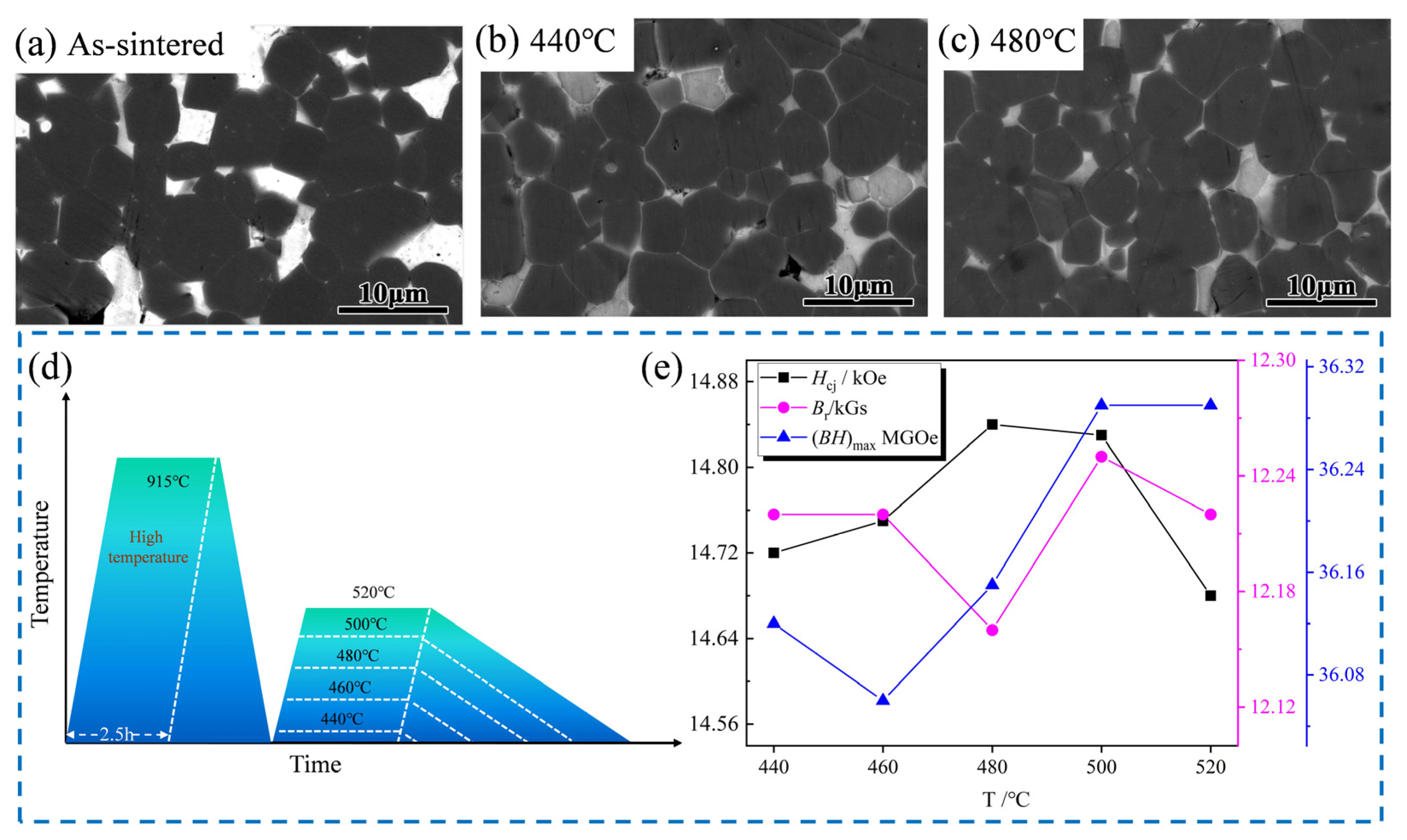
| Sample | High Temperature/°C | Low Temperature/°C | Hcj (kOe) | Br (kGs) | (BH)max (MGOe) |
|---|---|---|---|---|---|
| Sintered state | — | — | 13.65 | 12.10 | 31.58 |
| 1 | 915 °C × 2.5 h | 440 °C × 5 h | 14.72 | 12.22 | 36.12 |
| 2 | 915 °C × 2.5 h | 460 °C × 5 h | 14.75 | 12.22 | 36.06 |
| 3 | 915 °C × 2.5 h | 480 °C × 5 h | 14.84 | 12.16 | 36.15 |
| 4 | 915 °C × 2.5 h | 500 °C × 5 h | 14.83 | 12.25 | 36.29 |
| 5 | 915 °C × 2.5 h | 520 °C × 5 h | 14.68 | 12.22 | 36.29 |
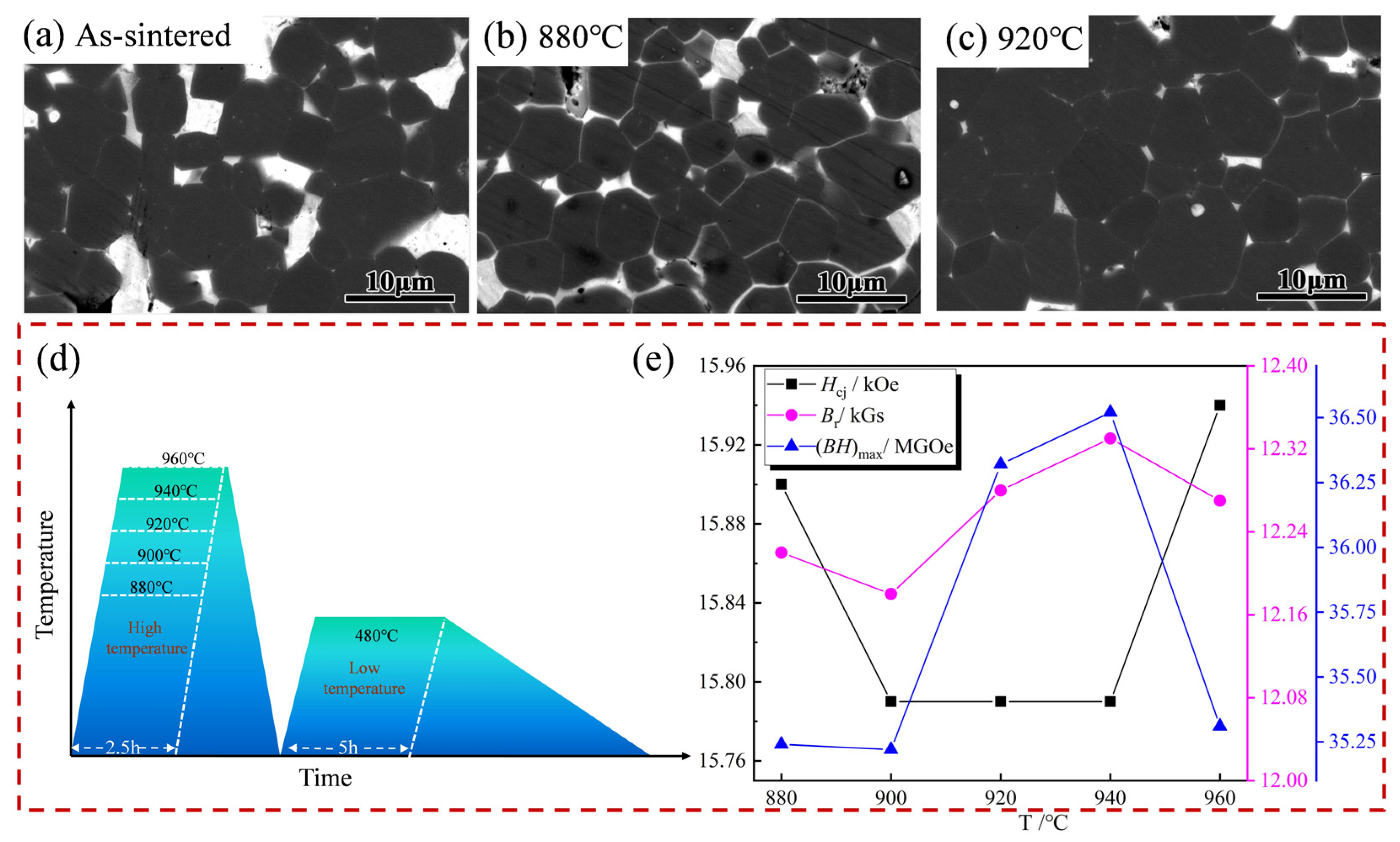
| Sample | High Temperature/°C | Low Temperature/°C | Hcj (kOe) | Br (kGs) | (BH)max (MGOe) |
|---|---|---|---|---|---|
| Sintered state | — | — | 13.65 | 12.10 | 31.58 |
| 1 | 880 °C × 2.5 h | 480 °C × 5 h | 15.90 | 12.22 | 35.24 |
| 2 | 900 °C × 2.5 h | 480 °C × 5 h | 15.79 | 12.18 | 35.22 |
| 3 | 920 °C × 2.5 h | 480 °C × 5 h | 15.79 | 12.28 | 36.32 |
| 4 | 940 °C × 2.5 h | 480 °C × 5 h | 15.79 | 12.33 | 36.52 |
| 5 | 960 °C × 2.5 h | 480 °C × 5 h | 15.94 | 12.27 | 35.31 |
Disclaimer/Publisher’s Note: The statements, opinions and data contained in all publications are solely those of the individual author(s) and contributor(s) and not of MDPI and/or the editor(s). MDPI and/or the editor(s) disclaim responsibility for any injury to people or property resulting from any ideas, methods, instructions or products referred to in the content. |
© 2025 by the authors. Licensee MDPI, Basel, Switzerland. This article is an open access article distributed under the terms and conditions of the Creative Commons Attribution (CC BY) license (https://creativecommons.org/licenses/by/4.0/).
Share and Cite
Dai, Y.; Wang, K.; Xiang, J.; Yao, Q.; Lu, Z.; Wang, J. Magnetic Properties and Corrosion Resistance of Sintered Nd-Fe-B Magnet Caused by Er69Fe31 Alloy Grain Boundary Addition. Materials 2025, 18, 2711. https://doi.org/10.3390/ma18122711
Dai Y, Wang K, Xiang J, Yao Q, Lu Z, Wang J. Magnetic Properties and Corrosion Resistance of Sintered Nd-Fe-B Magnet Caused by Er69Fe31 Alloy Grain Boundary Addition. Materials. 2025; 18(12):2711. https://doi.org/10.3390/ma18122711
Chicago/Turabian StyleDai, Yongtao, Kai Wang, Jing Xiang, Qingrong Yao, Zhao Lu, and Jiang Wang. 2025. "Magnetic Properties and Corrosion Resistance of Sintered Nd-Fe-B Magnet Caused by Er69Fe31 Alloy Grain Boundary Addition" Materials 18, no. 12: 2711. https://doi.org/10.3390/ma18122711
APA StyleDai, Y., Wang, K., Xiang, J., Yao, Q., Lu, Z., & Wang, J. (2025). Magnetic Properties and Corrosion Resistance of Sintered Nd-Fe-B Magnet Caused by Er69Fe31 Alloy Grain Boundary Addition. Materials, 18(12), 2711. https://doi.org/10.3390/ma18122711